MDF-U500VX MDF-U500VXC
|
|
|
- Morris Berry
- 7 years ago
- Views:
Transcription
1 Service Manual Ultra-Low Temperature Freezer MDF-UVX MDF-UVXC FILE No. SANYO Electric Co., Ltd. Biomedical Business Division SM
2 Effective models This service manual is effective for following models. Model name Product code Voltage and Frequency V Hz MDF-UVX V Hz V Hz V Hz MDF-UVXC V Hz
3 Contents Page S p e c i f i c a t i o n s Structural specifications -Control specifications -Performance specifications D i m e n s i o n s Cooling unit parts Refirigeration circuits C o m p o n e n t s o n P C B C o n n e c t i o n s o n P C B W ir ing dia gr a m Circuit diagram E l e c t r i c p a r t s Specification of sensor Specifications of LCD panel Control specifications P a r t s l a y o u t Repair of cooling unit Troubleshooting Abnormal in cooling circuit -Abnormal in fan motor -Abnormal in sensor -High temperature alarm -Low temperature alarm -Power failure alarm -Door alarm T e s t d a t a Pull-down & Pull-up data -Pull-down temperatures -Pull-down pressure data -Pull-down current input data -Temperature uniformity points measured -Amount of power consumption -Sample load test I n s t r u c t i o n m a n u a l
4 Specifications Structural specifications Item Name External dimensions Internal dimensions Effective capacity Exterior Interior Outer door Inner door Shelf Insulation Access port Compressor Evaporator Condenser Refrigerant Refrigerating oil Power supply Battery Weight Accessories Optional component MDF-UVX / MDF-UVXC Ultra-Low Temperature Freezer W D H (mm) W D H (mm) L Painted steel Painted steel, Painted steel, ABS resin panel with stainless frame, Stainless steel Rigid polyurethane foamed-in place + vacuum insulation panel (VIP PLUS) mm, locations (in upper back, bottom left/right back) A circuit; Hermetic type, Output; W B circuit; Hermetic type, Output; W A circuit; Tube on sheet type B circuit; Tube on sheet type A circuit; Finless tube type B circuit; Finless tube type A circuit; MU-N B circuit; MU-N LABSA Local voltage Nickel-hydrogen storage battery for power failure alarm, VDC, mah, Auto-recharge kg / kg set of key, scraper Temperature recorder (MTR-H), Mounting kit for MTR-H (MDF-S) Back-up kit (CVK-UB, CVK-UB(I)):LCO, Communication IF board (MTR-), LAN interface board (MTR-L), Software (MTR-) pin Dsub cross type (RSC) - -
5 Control specifications Item Temp. controller Temp. sensor Temp. display Alarm High temp. Low temp. Power failure Door Control panel Remote alarm Battery life Fan motor life Fan lock Cooling circuit is abnormal MDF-UVX / MDF-UVXC Micro-processor control system Setting range; --Unit; Non-volatile memory Platinum resistance; Pt. LED digital display (Unit; ) Display: time, date (Back-up by battery during power failure) Setting range: +~+ (Initial; +) ALARM lamp and LCD display flashes, intermittent buzzer tone with delay. (Initial: min.) Remote alarm contact activates with delay. (Range:~min.) Setting range: -~- (Initial; -) ALARM lamp and LCD display flashes, intermittent buzzer tone with delay. (Initial: min.) Remote alarm contact activates with delay. (Range:~min) When the power to the unit is disconnected or in power failure, ALARM lamp flashes and intermittent buzzer tone emitted. Remote alarm contact activates. When outer door is open, indication is shown. ALARM lamp blinks and buzzer beeps intermittently with ~ min. delay. (Initial: min.) P remote alarm terminal: Max. DCV, A, NC-COM, NO-COM Battery accumulation time expires about. years, message is shown. Fan motor accumulation time expires about. years, message is shown. In the event fan motor is locked, ALARM lamp blinks, buzzer beeps intermittently, remote alarm activates and message is shown. Occurrence date and time is stored. In the event cooling circuit is abnormal, ALARM lamp blinks, buzzer beeps intermittently, remote alarm activates and message is shown. Lamp: ALARM Buzzer stop key: BUZZER Menu key: MENU Clear key: CE Entry key: ENT Figure input key LCD contrast adjusting knob: CONT Shift key: - -
6 Item Key Lock function Self diagnosis function Status monitor function Power source voltage is abnormal Ambient temp. is abnormal Notice of overload run Compressor protection Activates on LED digital display. Password is settable. MDF-UVX / MDF-UVXC In the event of any failure among temp. sensor, AT sensor, Comp. sensor, message is displayed, intermittent buzzer beeps and remote alarm activates. Message emits when power supply voltage is % lower than rated power supply. Message emits when ambient temperature is equal or higher than, and equal or lower than. Message emits when compressor keeps operation for days. When temperature in Comp. sensor is equal or higher than +, compressor turns off. Overload relay Performance specifications Model Cooling performance Temp. control range Rated power consumption Noise level Maximum pressure MDF-UVX Center of chamber; - AT, no load --AT, no load VAC, Hz VAC, Hz VAC, Hz VAC, Hz W W W W db (A) (background noise; db) kpa Model Cooling performance Temp. control range Rated power consumption Noise level Maximum pressure MDF-UVXC Center of chamber; - AT, no load --AT, no load VAC, Hz W db (A) (background noise; db) kpa Note: Specifications will be subject to change without notice. - -
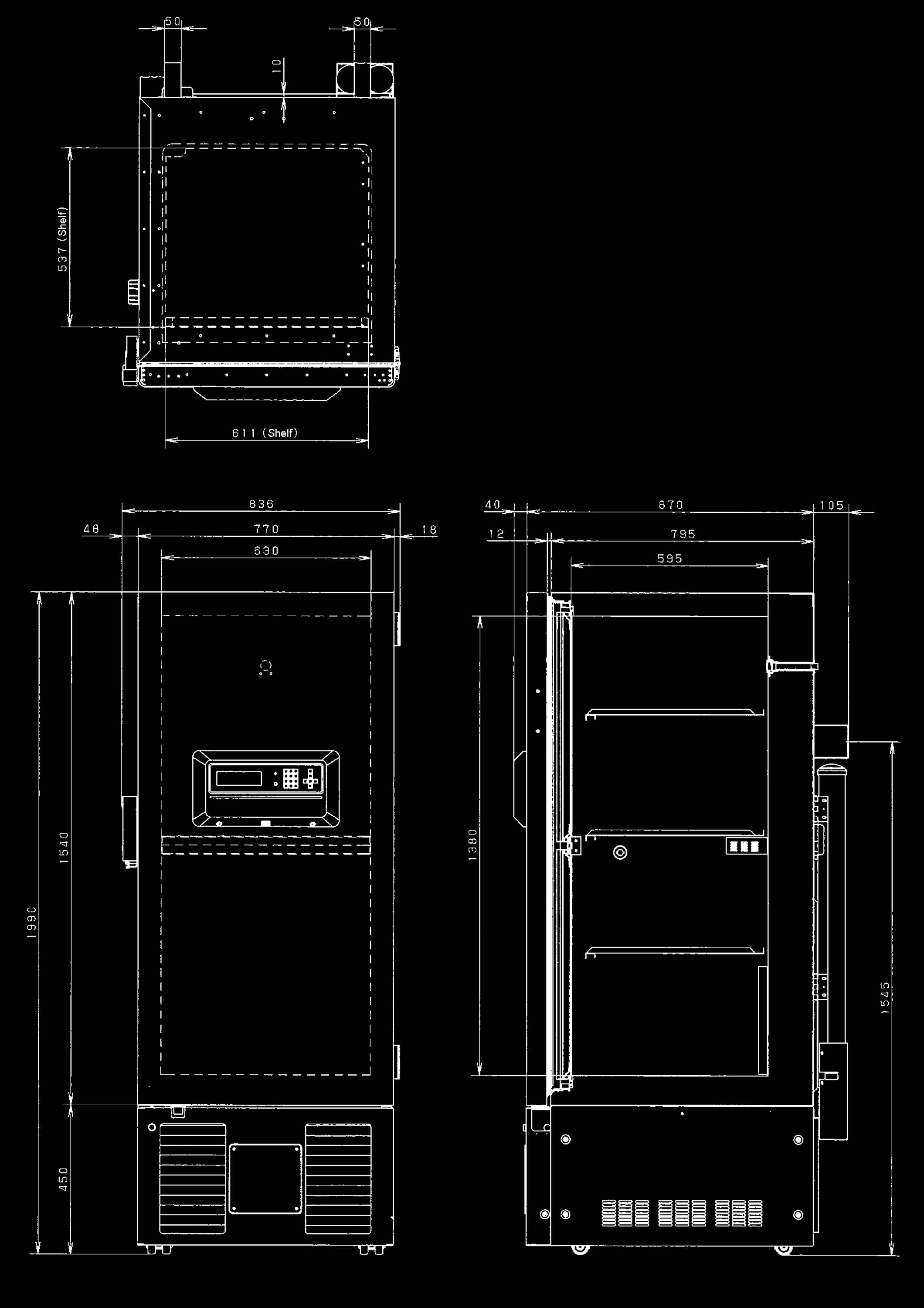
7 Dimensions - -
8 Cooling unit parts Parts description Specification A circuitleft side at rear view B circuitright side at rear view Compressor For V, Hz* Type KSJNS-A KSJNS-A Compressor cord FB--M-- FB--M-- Rated power supply Single phase, /V, Hz Single phase, /V, Hz Refrigeration oil Ze-NIUSLSA Qty:cc Ze-NIUSLSA Qty:cc Cooling method Forcible air circulationpartially Forcible air circulationpartially and oil cooler and oil cooler For /V, Hz Type KSJNS-A KSJNS-A Compressor cord FB--M-- FB--M-- Rated power supply Single phase, /V, Hz Single phase, /V, Hz Refrigeration oil Ze-NIUSLSA Qty:cc Ze-NIUSLSA Qty:cc Cooling method Forcible air circulationpartially and oil cooler - - Forcible air circulationpartially and oil cooler For V, Hz Type KSJNS-A KSJNS-A Compressor cord FB--M-- FB--M-- Rated power supply Single phase, V, Hz Single phase, V, Hz Refrigeration oil Ze-NIUSLSA Qty:cc Ze-NIUSLSA Qty:cc Cooling method Forcible air circulationpartially and oil cooler Forcible air circulationpartially and oil cooler Condenser Type Finless tube Finless tube Condenser columns x lines x Wmm columns x lines x Wmm Pre-condenser W. columns W. columns Frame pipe.. Cascade condenser Double tube coil Double tube coil W x columns x W x columns x Evaporator Tube on sheet,. Tube on sheet,. Type Sharing with interior Sharing with interior Capillary tube Upper Lower EX cap. Upper Lower EX cap. Resistance.MPaG.MPaG.MPaG.MPaG.MPaG.MPaG Lengthmm mm mm mm mm mm mm Outer diameter.mm.mm.mm.mm.mm.mm Inner diameter.mm.mm.mm.mm.mm.mm Color None Black White None Black White Refrigerant HFC mixed Charge qty: g MU-N HFC mixed Charge qty: g MU-N Dryer AXH- Charge qty: g AXH- Charge qty: g Condensing fan Material: ABS Blade: pcs. Material: ABS Blade: pcs. Condensing fan motor Type SE-ELP Output: W SE-ELP Output: W
9 Refrigeration circuit Compressor Cap.tube (EX) EX tank Evaporator Cascade condenser - - B circuit Frame pipe Pre-condenser Condenser Dryer Shunt Cap.tube Cap.tube A circuit Condenser Frame pipe Pre-condenser Dryer Shunt Cap.tube Cap.tube Cascade condenser Compressor Cap.tube (EX) EX tank Evaporator
10 Components on PCB CN #-# To LCD PCB CN #-# To AT sensor #-# To Comp.sensor A #-# To Comp.sensor B - - CN To Temp.sensor CN # To Fan motor relay B # To days recorder (Option) # To Fan motor relay A # To days recorder (Option) CN To Door switch CN #-# To Contol relay B #-# To Fan motor relay B #-# To Heater relay B CN #-# To Battery, Battery switch #-# To Transformer CN #-# To Contol relay A #-# To Fan motor relay A #-# To Heater relay A CN To Remote alarm terminal CN To MTR- (Option) CN To Switching power supply
11 Connections on PCB The following shows connections of connector on Main PCB. Connector Connects to Usage CN Switching power supply #: DCV To supply the power to PCB. #: GND CN MTR-/MTR-L (Option) To connect with MTR-/MTR-L. CN Remote alarm terminal #: COM #: N.O. Remote alarm contact outputs. #: N.C. CN # - #: Temp. control relay A # - #: Fan motor relay A # - #: Heater relay A To control chamber temperature To control condensing fan motor A To control cap. Tube heater A CN # - #: AT sensor # - #: A comp. sensor # - #: B comp. sensor To detect ambient temperature To detect temperature of compressor A To detect temperature of compressor B CN # - #: Battery (DCV), battery switch To supply the power during power failure. # - #: Transformer CN # - #: Temp. control relay B # - #: Fan motor relay B # - #: Heater relay B To control chamber temperature To control condensing fan motor B To control cap. Tube heater B CN Temp. sensor #: PT sensor To detect chamber temperature #: GND CN # - #: LCD PCB (CN) To connect with LCD PCB CN # - #: Door switch To detect door open and shut CN # - #: Fan motor relay B # - #: Fan motor relay A - -

12 Wiring diagram - -

13 Circuit diagram < Main PCB > - -

14 < LCD PCB > - -
15 Electric parts MDF-UVX/UVXC V, Hz V, Hz* /V,Hz Compressor A/B Type KSJNS-A KSJNS-A KSJNS-A * Compressor for china (CCC Authorization) Compressor code FB--M-- FB--M-- FB--M-- Type: KSJNS-AD Rating, V, Hz, /V, Hz, /V, Hz Code: FB--M-- Winding resistance (C-R)... C-S)... Starting capacitor A/B Rating μf, ACV μf, ACV μf, ACV Running capacitor A/B Rating μf, ACV μf, ACV μf, ACV Starting relay A/B Type AMVL-A AMVL-A AMVL-A Rating ACV ACV ACV Overload relay A/B Type MRA MRA MRA Action to the temp. (no current) ON: OFF: ON: OFF: ON: OFF: Operation time ~ sec. with.a ~ sec. with.a ~ sec. with.a Condensing fan motor A Type SE-ELP SE-ELP SE-ELP Rating ~V ~V ~V Condensing fan motor B Type SE-ELP SE-ELP SE-ELP Rating ~V ~V ~V Capitube heater A/B Rating V, W V, W V, W Resistance) Control relay A/B Type GF-T GF-T GF-T Contact capacity A A A Coil DCV DCV DCV Heater relay A/B Type GR-A-T GR-A-T GR-A-T Contact capacity V, A V, A V, A Coil DCV DCV DCV Fan motor relay A/B Type GR-A-T GR-A-T GR-A-T Contact capacity V, A V, A V, A Coil DCV DCV DCV Temp. sensor Type PT sensor (THC-) PT sensor (THC-) PT sensor (THC-) Rating Comp. sensor A/B Type AT- AT- AT- Rating K, K, K, AT sensor Type AT- AT- AT- Rating K, K, K, Switching power supply Type ZWS--/J ZWS--/J ZWS--/J Rating DCV,.A DCV,.A DCV,.A Transformer Type S-UPV S-UPV S-UPV Voltage P:V S:V P:V S:V P:V S:V Battery Type HR-AAC HR-AAC HR-AAC Rating V, MAH V, MAH V, MAH Battery switch Type SLEA- SLEA- SLEA- Rating A, ACV A, ACV A, ACV Breaker switch Type BAM BAM BAM Rating V, A V, A V, A Door switch Type SDKNA SDKNA SDKNA Rating V, MA V, MA V, MA Noise filter Type RSAN- RSAN- RSAN- Rating ACV, A ACV, A ACV, A Breaker switch Type IRAER (for MDF-UVXC only) Rating ACV, A Power trans. (for booster) Type ATR-D (for MDF-UVXC only) Voltage P:V S:V Power trans.(for voltage detection) Type ATR-HJTC (for MDF-UVXC only) Voltage V, V, V Power relay Type GL-A-TUB (for MDF-UVXC only) Contact capacity V, A Coil DCV Boost relay Type GL-A-TUB (for MDF-UVXC only) Rating V, A Coil DCV - -
16 Specifications of sensor Temperature and resistance in temp. sensor (Type: AT-) Temp. () Resistance (k) Temp. () Resistance (k) Temp. () Resistance (k) Temp. () Resistance (k) Temperature and resistance in temp. sensor (Type: PT) Temp. () Resistance (k) Temp. () Resistance (k) Temp. () Resistance (k)
17 Specifications of LCD panel. Basic screen T o p S c r e e n T e mp - o C C o n t r o l : N o r m a l Al a r m N o r m a l S t a t u s S t a n d - b y D oor C l o s e d / / : :. When the power supply switch is turned on, basic screen of LCD panel illuminates. The numerical value after Temp shows set temperature, and a larger number under that shows present chamber temperature. The bottom of the screen shows a present date and time. Control Display (Control): The display shows current operation mode. Normal : Normal operation mode ECO : Energy saving operation mode * * Setting of Energy saving operation mode is referred to P. [Setting of Energy saving operation mode]. Alarm Display (Alarm): During alarm, Alarm will blink. Warning is indicated in reverse and non-reverse character at the time of warning. Normal is usually indicated. The complementary message is indicated in the message column. Alarm Indicated in delay time of high/low temp. alarm Warning Indication of remoate alarm activation Status Display (Status): Status_X (X: Status number) is indicated in the presence of abnormal ambient temperature or abnormal power supply voltage or overloaded operation. Status_: Notice of abnormal ambient temperature Status_: Notice of abnormal power supply voltage Status_: Notice of overloaded operation Stand-by is usually indicated. Complementary message is indicated in the message column. Door Display (Door): Open is indicated in reverse character while the door open. If the door is left open beyond the predetermined time setting, Open is indicated in the reverse and non-reverse characters and audible alarm sounds intermittently. When the door is closed, Closed is indicated in normal condition on the display. Message Display: The message is indicated in the Warning or Status. Note: There are no lights in the LED screen and ALARM lamp blinks in the power failure.. Menu button (MENU) Push MENU botton to indicate/set up each parameter. Select item by using numerical value shift key in MENU. Press ENTER key to set up each parameter. T o p S c r e e n M E N U T e mp - o C C o n t r o l : S T D S e t A l a r m N or m a l L o g S t a t u s S t a n d - b y To o l s D oor C l o s e d / / : : - -
18 MENU/Set Temperature/alarm setting Basic Screen T o p S c r e e n M E N U Te mp - o C S e t Al a r m Nor m a l Lo g S t a t u s S t a n d - b y To o l s Door Cl o s e d / / : : Temperature Setting Screen T e mp. S e t t i n g T e mp e r a t u r e - o C ( - o C - - o C ) H i g h A l a r m + o C ( + o C - + o C ) L o w A l a r m - o C ( - o C - - o C ) A l a r m D e l a y mi n ( - mi n ) R i n g B a c k mi n (. OF F - m i n ) K e y L o c k (. U n l o c k. L o c k ) Temperature setting range: -- Factory default: - High temp. alarm setting range: Set temp.+ + Factory default: + Low temp. alarm setting range: Set temp.- - Facotry default: - Alarm Delay : Settable range of alarm delay time is minutes. When it is set up in minute, the buzzer sounds immediately with no delay. (Factory default: min.) Ring Back : This is the time between the acknowledgement of alarm buzzer and return of the alarm buzzer. The settable range is minutes. Alarm buzzer is not back again when it is set in.factory default: min. ) Key Lock : When Lock is chosen, the set point cannot be changed. Input of the password is necessary to release. (Factory default: ) Temperature setting, high/low temp. alarm temperature, alarm delay time, Ring Back time cannot be changed when Key Lock is on. Note Alarm buzzer sounds after minutes delay (Factory default) once the unit is in an alarm condition. Release of Key Lock T e mp. S e t t i n g K e y L o c k M E N U T e mp e r a t u r e - o C ( - o C - - o C ) O K H i g h A l a r m + o C ( + o C - + o C ) C a n c e l L o w A l a r m - o C ( - o C - - o C ) A l a r m D e l a y mi n ( - mi n ) R i n g B a c k mi n (. O F F - m i n ) K e y L o c k P a s s w o r d It is necessary to input the password to release key lock. (Factory default: ) If you forget the password; In Select Tools Svc screen, select Calibration and Function. Input to indicate a current password forcibly. - -
19 Alarms Temperature alarm buzzerintermittent tone The buzzer will sound intermittently when a high temp. alarm or a low temp. alarm occurs, assuming that the alarm condition goes on for more than the preset delay for the alarm time. Push alarm BUZZER key to stop the alarm. The buzzer sounds again if an alarm is not resolved during the predetermined Ring Back time. Buzzer (intermittent tone) sounds and message is indicated if an alarm automatically returns. When an alarm returns automatically, press BUZZER key to eliminate the message indication and to stop buzzer sounding. Power failure alarm buzzer (intermittent tone) When a unit returns from power failure, the message of time power interruption is indicated and buzzer sounds intermittently. Press BUZZER key to eliminate the message indication and to silence the buzzer. Door alarm buzzerintermittent tone Alarm will sound if the door is left open beyond the predetermined time setting for Door Delay. It stops if the door is closed or BUZZER key is pressed. Remote alarm contact does not activate. Fan lock alarm buzzer (Intermittent tone) Alarm will sound and the message will appear on the display if either condensing fan motor A or B is locked. Safety function: If the unit detects a locked fan motor, the abnormal condensing fan motor stops and the other fan motor continues operation. Compressor is controlled as usual. Cooling circuit abnormal alarm buzzer (Intermittent tone) Alarm will sound with an intermittent tone and the message will appear if A or B circuit is abnormal. Safety function: Compressor is controlled as usual. Remote alarm contact activates. <Examples of alarm indication> High temp. alarm T o p S c r e e n T e mp - o C C o n t r o l : N or ma l A l a r m Wa r n i n g S t a t u s S t a n d - b y D o o r C l o s e d H i g h T e m p Wa r n i n g / / : : / / : : Power failure alarm T o p S c r e e n T e mp - o C C o n t r o l : N or mal A l a r m A l a r m S t a t u s S t a n d - b y D o o r C l o s e d Power f ai l ur e Wa r n i n g / / : : / / : : Fan lock alarm T o p S c r e e n T e mp - o C C o n t r o l : N or mal A l a r m W a r n i n g S t a t u s St and- by D o o r C l o s e d E r r o r F a n mo t o r B a b n o r ma l. / / : : Cooling circuit abnormal alarm T o p S c r e e n Temp - o C C o n t r o l : N or mal A l a r m Wa r n i n g S t a t u s St and- by D o o r C l o s e d E r r o r C o o l i n g c i r c u i t A a bnor ma l. / / : : - -
20 . MENU/Log Basic Screen T o p S c r e e n M ENU T e mp - o C C o n t r o l : S T D Set A l a r m Nor mal L o g S t a t u s St and- by Tool s D o o r C l o s e d / / : : Graph display ( - C ) / / C h a mb e r T e mp M ENU P C D P C A l l C l e a r Cancel ( - C ) All accumulated records are indicated with a graph point. page provides -hours of data Temperature range is changed with and. Temperature: - for page, -- for page It is moved with and to date. : Older date : Newer date Data interval: minutes Factory default: min. With min. interval, recording for about weeks is available Display resolution: /point, min./point When log data memory is full, the oldest data is written over. Press Clear button to display confirmation screen. Select MENU/OK to eliminate all log data. Press PC D button to display confirmation screen. Log data for one day (displayed date) is transferred. Press PC ALL button to display confirmation screen. All memory log data will be transferred. <Log data> Chamber temperature, compressor A/B protection temperature, ambient temperature, door open/close (: Open, :Close), cooling circuit abnormality, fan motor abnormality The communication cable for the interface board MTR- option and pin Dsub cross type for RSC is necessary for the data transmission to PC. Operation of hyper-teminal on PC side Specify transmission, text capture and file name, press start button. Data transmission P r o g r e s s S e n d l o g d a t a t o P C. Log Dat e / / Fi ni shed. MENU St ar t Ca nc e l Select MENU/Start to transmit the data to PC. The transmission is complete when the message Finished is indicated. PC setting for receiving log data for Windows, XP. Start a program accessories communication hyper-terminal from the starting button. The registration of the starting menu is to start in the following method, C: Program Files Windows NT hypertrm.exe. Set up the following through the hyper-terminal screen. New connection Name Ex.Sanyo Set up of connection Connection port COM Properties of COM Set up of port Bit/Sec., Data bit:, Parity: No, Stop bit:, Flow control: Xon/Xoff When a log transmitting screen is opened, terms of communication on the MDF side are set on the above condition automatically.. The communication cable for the interface board MTR- option and pin Dsub cross type for RSC is necessary for the data transmission to the PC. - -
21 - - D e f a u l t S e t t i n g L C D B a c k C o l o r (. B l u e. Wh i t e) D A Q S p e e d (.. ) D A Q I D (. O F F - ) D A Q M o d e (. L o c a l. R e mo t e) R e mo t e A l a r m (. O F F. A c t i v e ) C o n t r o l (. N o r ma l. E C O ) MENU O K Ca nc e l S e l e c t T o o l s M D F - U V X D e f a u l t S e t t i n g D a t e T i me K e y L o c k P W S e t t i n g MENU O K Svc Cancel T o p S c r e e n T e mp - o C C o n t r o l : S T D A l a r m Nor mal S t a t u s St and- by D o o r C l o s e d / / : : MENU Set Log T o o l s Da t e T i me Dat e / / ( Y Y / MM/ D D ) T i m e : : ( h h mm s s ) DOOR D e l a y mi n ( - mi n ) Log I nt er val mi n ( - mi n ) Co m p D e l a y mi n ( - mi n ) MENU O K Cancel. MENU/Tools Select Tools Date Time, Default Setting, Key Lock PW Setting Setting of date, Initialization, Setting of Key lock password Setting of date, time Log interval Top Screen Select Tools Initialization Parameter setting range January st, :: is set. It is input with in the Date cell. It is input with in the Time cell. It is memorized with MENU/OK (ENTER). Door Delay is setting of door alarm delay time. The variable range is ~ minutes. (Factory default: min.) Log Interval is settable between ~ minutes. Factory default: min. With min. interval, recording for about weeks is available. Comp Delay is delay time for A/B side compressor after power failure. (Initial: min. Settable range is ~min.) There is a priority on A side compressor to B side compressor on initial start. Setting of LCD Back Color:.Blue.White DAQ Speed should use.. It is DAQ standard command mode. DAQ ID: Select any ID between and when an optional interface board is attached. DAQ Mode:.Local setting change from PC side is not possible..remote change of Stand-by Setting screen is not possible. Remote is indicated on the upper right of the Stand-by Setting screen. Remote Alarm contact : Inactive :Active Control: Setting of operation mode Normal (W-ONOFF mode) ECO (Energy saving mode) Ke y L o c k PW S e t t i n g Cu r r e n t Use r Pa s s w o r d Ke y L oc k PW S e t t i n g N e w U s e r P a s s wo r d Ke y L o c k P W S e t t i n g Ne w U s e r P a s s wo r d Re Ent er User Pas s w o r d Current password input * Initial New password input New password input again to store
22 - - <Setting of ECO (energy saving) mode> Operation Key Display Top Screen is displayed. Press MENU key. MENU (Set) is displayed with reverse characters on MENU window. Press key to display (Tools) with reverse characters in MENU window. Press ENTER key. ENTER Select Tools is displayed. Press key to select (Default Setting). Default Setting is displayed with reverse characters. Press ENTER key. ENTER Default Setting is displayed. Press key to select Control. Numerical value besides Control is displayed with reserse characters. Input by figure input key. is displayed besides Control. Press MENU key. MENU MENU window is displayed. Display (OK) with reverse characters and press ENTER key. OK ECO mode is memorized and automatically returns to (Select Tool Note) When you set unit in ECO mode, compressors will run in energy-saving mode. Comparing the energy-saving effect in ECO mode with in normal mode, it will be % less annually in ECO mode than normal mode. However, there may be occasional variances to chamber temperature uniformity if set in ECO mode. Normal mode is recommended in a GXP environment or if temperature data is being logged for regular purposes. T o p S c r e e n Te mp - o C C o n t r o l : N or mal Al a r m N or mal S t a t u s St and- by D oor C l o s e d / / : : D e f a u l t S e t t i n g L C D B a c k C o l o r (. B l u e. Wh i t e) D AQ S p e e d (.. ) D A Q I D (. O F F - ) D A Q M o d e (. L o c a l. R e mo t e) R e mo t e A l a r m (. OFF. Act i ve) C o n t r o l (. N o r ma l. ECO) MENU O K Ca nc e l T o p S c r e e n Te mp - o C C o n t r o l : S T D A l a r m N or mal S t a t u s St and- by D oor C l o s e d / / : : MENU Se t Log T o o l s S e l e c t T o o l s M DF - U V X D e f a u l t S e t t i n g D a t e T i me K e y L o c k P W S e t t i n g M ENU O K Svc Cancel T o p S c r e e n T e mp - o C C o n t r o l : E C O A l a r m N or mal S t a t u s St and- by D oor Cl osed / / : :
23 - - -Display of Status -Calibration. MENU/Tools Select Tools Svc (Service only) -.How to access Service mode S e l e c t T o o l s S v c V e r.. S t a t u s C a l i b r a t i o n C a l i b r a t i o n Test Pr ogr am I n i t i a l i z e D a t a Fl ashw r i t e Pr ogr a m MENU O K Ca nc e l T o p S c r e e n T e mp - o C C o n t r o l : S T D A l a r m Nor mal S t a t u s St and- by D o o r C l o s e d / / : : MENU Set Log T o o l s C a l i b r a t i o n C h a mb e r T e mp. -. o C. A mb i e n t T e mp.. o C. C o n d e n s e r T e mp A.. o C. Con d e n s e r Te mp B.. o C. P o w e r S u p p l y % MENU O K Ca nc e l H a r d wa r e S t a t u s Temp SV -. C A mb T e mp. C Ba t t e r y Temp PV -. C P o w e r % d a y Comp PV ONO F F C o n d e n T F A N A % O N. C d a y B % O F F. C d a y S e l e c t T o o l s M DF - U V X D e f a u l t S e t t i n g Da t e T i me Ke y L oc k PW S e t t i n g MENU OK S v c Ca nc e l P a s s w o r d F o r S e r v i c e T o o l s P a s s w o r d M a i n B o a r d V e r.. L C D B o a r d V e r.. MENU O K Ca nc e l Password Basic Screen Select Tools screen for service Calibration for chamber temp, ambient temp, A/B condenser temp Example display of Status Select Tools S e l e c t T o o l s S v c V e r.. S t a t u s C a l i b r a t i o n C a l i b r a t i o n T e s t P r o g r a m I n i t i a l i z e D a t a F l a s h W r i t e P r o g r a m MENU O K Cancel Select Tools screen for service Example of Status display Temp SV -. <Meaning> Chamber temp. setting is -.. Amb Temp. <Meaning> Ambient temp. is.. Battery day <Meaning> Battery accumulation time is day. Temp PV -. <Meaning> Current chamber temp. is -.. Power : <Meaning> Power supply voltage is at full specified voltage. Comp PV A <Meaning> Running rate of Compressor A is %. Comp PV B <Meaning> Running rate of Compressor B is %. ON/OFF / <Meaning> Compressor operation time ON:min. OFF:min. CondenT A. <Meaning> Condenser exit temperature in A circuit is.. CondenT B. <Meaning> Condenser exit temperature in B circuit is.. FAN A day <Meaning> Accumulation time of Fan motor A is day and a value exchanged from output voltage of current transformer in A circuit is. FAN B day <Meaning> Accumulation time of Fan motor B is days and a value exchanged from output voltage of current transformer in B circuit is. S e l e c t T o o l s S v c V e r.. S t a t u s C a l i b r a t i o n C a l i b r a t i o n T e s t P r o g r a m I n i t i a l i z e D a t a F l a s h W r i t e P r o g r a m MENU O K Cancel Select Tools screen for service Example display of Calibration Note) It is necessary to access Service mode prior to use the following functions.
24 -Calibration Select Tools screen for service Example display of Calibration C a l i b r a t i o n S e l e c t T o o l s S v c V e r.. MENU MENU S t a t u s C a p i H. T i me r (. O F F - mi n ) O K O K C a l i b r a t i o n C a p i H. S t a r t (. A u t o. ON ) Cancel Ca nc e l C a l i b r a t i o n T e s t P r o g r a m I n i t i a l i z e D a t a M o d e l C o d e (. V X. V X ) F u n c t i o n (. B C.. F C ) F l a s h W r i t e P r o g r a m -Setting of model code Setting of model code is done in Calibration. Capi H.Timer Cap. heater ON time is min. (Compressor is off for the period) Capi H Start Compressor is forcibly turned off for min. Pupose: Prevension for capillary blockage : Cap.heater is turned on once per hrs. : Compressor is forcibly turned on once : Compressor is forcibly turned off Model Code. MDF-UVX. MDF-UVX Function Key Lock password, reset of battery/fan motor accumulation time, non-volatile memory initialization C a l i b r a t i o n C a p i H. T i me r (. OFF - mi O Kn) C a p i H. S t a r t (. Aut o. ON Cancel. OFF) C o mp C o n t r o l (. E.. A. N ) F A N C o n t r o l (. O F F. A. B. A B ) M o d e l C o d e (. VX. VX) F u n c t i o n (. B C.. F C ) - - MENU S e l e c t T o o l s M D F - U V X V e r.. D e f a u l t S e t t i n g D a t e T i me K e y L o c k P W S e t t i n g Model Code MDF-UVX Model Code MDF-UVX Display of model code in Select Tools screen is changeable depending on model code. Controls of micro-processor on Main PCB Temperature control in ECO mode Temp. display offset value Temp. offset value in ECO mode Function # Function Factory default mode Key Lock password is forcibly displayed Display of log (A/B condenser temp., ambient temp.) Unused (Factory test mode) Reset of battery accumulation time Reset of fan motor A accumulation time Reset of fan motor accumulation time Initialization of non-volatile memory Set and select MENU/Tools - Svc Initialize Data. Turn the power off and on to reset non-volatile memory. Function # is changed to after the reset. (Note) It is also necessary to calibrate temperature after the reset. Note) It is necessary to set model code when a PCB is replaced. Input alternative numerical value and select MENU and OK. Press ENTER key to set model code. If you input numerical value other than or, model code is automatically set to.
25 - - -Maintenance function Tes t r un Pr ogr am C y c / D e c o C Ti me : : : : : : Temp MENU S t a r t Ca nc e l C onf i r ma t i on Ar e y ou s ur e t o d e l e t e Al l Us e r Na me s a n d P r o g r a m s MENU OK C a n c e l Test run screen (for factory use) Note. Initialization of data for calibration and accumulation time Set to Function in Calibration screen. See -. Calibration for details Select Initialize Data - MENU/OK to delete all data. Turn power off then on.. When reboot of flash memory MTR- (option), RSC (Dsub cross type cable, pins) and software are necessary to reboot flash memory. Data delete C o n f i r ma t i o n A r e y o u s u r e t o F l a s h a n d Wr i t e M e mo r y? MENU O K Ca nc e l Renewal of ROM version R e b o o t a f t e r p r o g r a m i n g. Reboot after programming Turn the power off then on after reboot. Note) This function is used only when non-volatile memory is initialized. Reboot for LCD PCB and Main PCB is available. S e l e c t T o o l s S v c V e r.. S t a t u s C a l i b r a t i o n C a l i b r a t i o n T e s t P r o g r a m I n i t i a l i z e D a t a F l a s h W r i t e P r o g r a m MENU O K Cancel Select Tools screen for service
26 - - -ROM version Operation MENU Turn the unit on. Basic Screen is displayed. Select Tools of MENU button to display Select Tools. Tools Select Svc of MENU button in Default setting is displayed in reverse characters. Svc ROM version for both Main PCB and LCD PCB is displayed on Password screen. T o p S c r e e n T e mp - o C C o n t r o l : S T D A l a r m Nor mal S t a t u s St and- by D o o r C l o s e d / / : : MENU Set Log T o o l s P a s s w o r d F o r S e r v i c e T o o l s P a s s w o r d M a i n B o a r d V e r.. L C D B o a r d V e r.. MENU O K Ca nc e l Password Basic Screen S e l e c t T o o l s M D F - U V X D e f a u l t S e t t i n g D a t e T i me Key Lock PW S e t t i n g MENU OK S v c Ca nc e l Select Tools screen for service
27 - - -Hardware status Operation MENU Turn the unit on. Select tools Svcis displayed. Select OK of MENU button. OK Hardware status is displayed on the upper right corner of screen. n c e S e l e c t T o o l s S v c S t a t u s C a l i b r a t i o n C a l i b r a t i o n T e s t P r o g r a m I n i t i a l i z e D a t a F l a s h W r i t e P r o g r a m MENU O K Cancel Select Tools Svc H a r d w a r e S t a t u s O V E R L A P T e mp S V -. C Amb T e mp. C B a t t e r y T e mp P V -. C P o w e r % d a y C o mp P V O N O F F C o n d e n T F A N A % ON. C d a y B % O F F. C d a y <Overlap operation> When either A or B circuit compressor decreases cooling performance, both compressors are kept running to maintain chamber temperature.
28 -Indication of Message Error codes Indication Error : Temperature Sensor Open Error : Temperature Sensor Short Error : Condenser Sensor A Open Error : Condenser Sensor A Short Error : Condenser Sensor B Open Error : Condenser Sensor B Short Error : Ambient temp Sensor Open Error : Ambient temp Sensor Short Error : Battery switch is off Error : Condenser temp is abnormal Error : Fan motor A abnormal Error : Fan motor B abnormal Error : Cooling circuit A abnormal Error : Cooling circuit B abnormal Meaning Temp. sensor is open circuited. Temp. sensor is short circuited. Sensor at exit of condenser in A circuit is open circuited. Sensor at exit of condenser in A circuit is short circuited. Sensor at exit of condenser in B circuit is open circuited. Sensor at exit of condenser in B circuit is short circuited. AT sensor is open circuited. AT sensor is short circuited. Battery switch is in off position. Condenser temp. is abnormal. (Both fan motor are locked ) Condensing fan motor A is abnormal.(condensing fan motor A is locked) Condensing fan motor B is abnormal.(condensing fan motor B is locked) Cooling circuit A is abnormal. Cooling circuit B is abnormal. <Status codes> Indication Meaning Status_ Ambient temp abnormal Ambient temp. is lower than, or higher than + Status_ Power-supply abnormal Power supply voltage is % lower than standard. Status_ Cooling circuits Overload Compressor keeps running over days. (Overloaded run) <Battery check> Indication Please exchange a battery Meaning Battery accumulation time (.years) expires. <Fan motor check> Indication Exchange fan motor A Exchange fan motor B Exchange fan motors A and B Meaning Accumulation time of Condensing fan motor A (.years) expires. Accumulation time of Condensing fan motor B (.years) expires. Accumulation times of both Condensing fan motor A and B (.years) expire. <Alarms> Indication High Temp Warning XX/XX/XX XX:XX:XX Low Temp Warning XX/XX/XX XX:XX:XX Power failure Warning XX/XX/XX XX:XX:XX Meaning Chamber temp. is higher than high temp. alarm set temp. (Year/Month/Date Time/Minute/Second) Chamber temp. is lower than low temp. alarm set temp. (Year/Month/Date Time/Minute/Second) Power failure has occurred, power switch is in off Position, or power cord is disconnected. (Year/Month/Date Time/Minute/Second) - -
29 Control specifications. Temperature control Settable range : - ~ - (For a maximum temp operation, when you input, the chamber temperature will be set to -.) Chamber temperature display range: - ~ + How to set chamber temperature: In TopScreen, press MENU key to step to setting mode. Select Temperature column and set using figure input key. Press MENU key and select OK to memorize the value.. Error codes and alarms () Error codes Error : When a temp. sensor input voltage is higher than mv, it diagnoses that temp. sensor is open circuited. Error : When a temp. sensor input voltage is lower than mv, it diagnoses that temp. sensor is short circuited. Error : When a comp. sensor A input voltage is higher than mv, it diagnoses that comp. sensor A is open circuited. Error : When a comp. sensor A input voltage is lower than mv, it diagnoses that comp. sensor A is short circuited. Error : When a comp. sensor B input voltage is higher than mv, it diagnoses that comp. sensor B is open circuited. Error : When a comp. sensor B input voltage is lower than mv, it diagnoses that comp. sensor B is short circuited. Error : When an AT sensor input voltage is higher than mv, it diagnoses that AT sensor is open circuited. Error : When an AT sensor input voltage is lower than mv, it diagnoses that AT sensor is short circuited. Error : When an Alarm Test performs with battery switch is off position, Error is indicated on TopScreen. Error : When a comp. sensor is higher than +, Error is indicated on TopScreen. Error : When a current in A circuit is abnormal, it diagnoses that fan motor A is locked. Error : When a current in B circuit is abnormal, it diagnoses that fan motor B is locked. Error : When self diagnosis is done between :~:a.m. and a unit detects twice that A circuit is abnormal, it diagnoses that A circuit is abnormal. Error : When self diagnosis is done between :~:a.m. and a unit detects twice that B circuit is abnormal, it diagnoses that B circuit is abnormal. () High temperature alarm Condition: When display temperature deviates from current set temperature and reaches high temp. alarm set temperature. Action: Temp. indication blinks, buzzer sounds intermittently and remote alarm contact activates after Alarm Delay time elapses. Press BUZZER key to stop buzzer sounding, however, remote alarm contact remains active. Remote alarm contact still activates if the buzzer sounds again after Alarm Delay time elapses. See page P. as for remote alarm operation. Setting range: High temp. alarm set temp: Set temp+~+(factory default = ) Alarm delay time: min.~min. When it is set in, alarm does not return. (Factory default = min.) Note) Chamber temperature is indicated and ALARM lamp blinks, but remote alarm contact does not activate until a chamber temperature reaches to high temp. alarm setting range during pull down. - -
30 () Low temperature alarm Condition: When display temperature deviates from current set temperature and reaches low temp.alarm set point. Action: Temp. indication blinks, buzzer sounds intermittently and remote alarm contact activates after Alarm Delay time elapses. Press BUZZER key to stop buzzer sounding, however, remote alarm contact remains active. Remote alarm contact still activates if the buzzer sounds again after Alarm Delay time elapses. See page as for remote alarm operation. Setting range: Low temp. alarm set temp: Set temp-~-(factory default = -) Alarm delay time: min.~min. When it is set in, alarm does not return. (Factory default = min.) Note) Chamber temperature is indicated and ALARM lamp blinks, but remote alarm contact does not activate until a chamber temperature reaches to high temp. alarm setting range during pull down. () Door alarm Condition: When a door is open beyond setting time Action: Buzzer sounds intermittently and Open is indicated in the reversal/non-reversal character on the display. When the door is closed or BUZZER key is pressed, buzzer stops sounding and remote alarm contact does not activate. Setting range: ~ minutes (Factory default = minutes) Ring Back: None (Open appears on display, DOOR indicatr on the TopScreen blinks.) () Power failure alarm Condition: When the power fails when battery switch is in the on position Action: Buzzer sounds intermittently, Warning appears on display, ALARM and Status_ in the STATUS in the TopScreen are indicated in the reversal/non-reversal character, and the message, power failure warning XXX (date, time) is indicated. When the power returns or BUZZER key is pressed, buzzer stops sounding. LCD back light illuminates for seconds with the BUZZER key is pressed.. Remote alarm Action: Remote alarm contact output Between COM and N.O. Between COM and N.C. normal Open Close power failure Close Open power not supplied Close Open Remote alarm and buzzer: = Remote alarm operation links with buzzer operation = Remote alarm operation does not link with buzzer operation If you select for Remote Alarm in the Default Setting screen, the operation of remote alarm links with the buzzer. (Factory default = ) Warning is indicated in the column, ALARM, in the TopScreen once remote alarm activates.. Ring Back In alarm condition (buzzer sounds), press BUZZER key to stop buzzer sounding at a while. Remote alarm operation does not link with buzzer operation. Ring Back does not activate if BUZZER key is pressed during the buzzer stops sounding. Setting range: ~ minutes. When you set in, buzzer does not sound again if you press BUZZER key.. Alarm delay time Alarm delay time is the time until unit is in alarm condition (remote alarm activates) since the temperature deviates from the temp. alarm setting value. Setting range: ~ minutes. When you set in, the unit will be in alarm with second delay. - -
31 . Normal mode a) Compressor operation ON: Compressor A turns on after minutes (factory default) elapsed time since the power is supplied. Compressor B turns on after minute after. Unit also performs this sequence in a cycle operation. OFF: Compressor A and B turns off simultaneously. After power failure: Compressor A turns on then Compressor B turns on with specificed delay time. When a unit reaches to set temp +., Compressor turns on. When a unit reached to set temp -., Compressor turns off. b) Compressor delay time There is a delay of minutes (Factory default) before the compressor will turn on during cycle operation to prevent compressor short cycling. c) Compressor protection When both Fan motor A and Fan motor B are locked and condenser temperature is + or higher, compressor will be turned off. d) Compressor normal control When comp. sensor temperature on Compressor A or Compressor B is lower than +, the compressor returns to normal operation. Note) Compressor also returns to normal operation when comp. sensor temperature is higher than + (comp. sensor is shorted). Operation sequence of Normal mode Compressor A turns on when a unit reaches to set temp +.( ON Point in the picture below). Compressor B turns on with minute of delay. Both Compressor A and B turns off simultaneously when unit reaches to set temp.( OFF Point in the picture below). ON Chamber temp. OFF Comp FAN Comp FAN on off on off on on on on o off o off o o o o - -
32 . ECO mode (Energy-saving mode) () Compressor alternate run Compressor A will cycle run alternately with Compressor B, when it is possible to maintain cycle operation with a single compressor. Purpose: To extend ON/OFF cycle duration for unit. a) When unit reaches set temp +., Compressor A turns on. b) When unit reaches set temp -., Compressor A turns off. c) When unit reaches set temp +., Compressor B turns on. d) When unit reaches set temp -., compressor B turns off. e) When unit reaches set temp +., unit switches from Compressor alternate run to Compressor overlapping run. f) When unit reaches to set temp -., unit switches from Compressor overlapping run to Compressor alternating run. Operation sequence of Compressor alternate run Compressor A turns on when unit reaches set temp +. (Point in the picture below) Compressor B does not turn on. Compressor A turns off when unit reaches set temp -. within minutes of compressor A turning on. Both compressor A and B turn off. Compressor B turns on when unit reaches set temp +. (Point in the picture below) Compressor A does not turn on. Compressor B turns off when unit reaches set temp -. within minutes of compressor B turning on. Both compressor A and B turn off. (Point in the picture below) ON Chamber temp OFF on off on off Comp off on o on Comp - -
33 ()Compressor overlapping run When unit cannot maintain cooling performance with a single compressor, compressor running time overlaps between Compressor A and B. a) When unit reaches set temp -.during compressor overlapping run, either Compressor A or B stops running. When unit reaches set temp -.for the st time during compressor overlapping run, Compressor B stops running. When a unit reaches set temp -.for the next cycle during compressor overlapping run, Compressor A stops running. b) When unit cannot maintain cooling performance with a single compressor and reaches set temp +., the stopped compressor will run. (Compressor overlapping run) c) When unit reaches to set temp -. in compressor overlapping run, either Compressor A or B stops running. (Compressor alternate run) Operation sequence of Compressor overlapping run Turn on both Compressor A and B. (Point in the picture below) When unit reaches set temp -.during compressor overlapping run, Compressor B stops running. (Point in the picture below) When unit reaches set temp +. within minutes, Compressor B will start running. (Point in the picture below) When unit reaches set temp -. in compressor overlapping run, Compressor A stops running. (Point in the picture below) ON Chamber temp OFF on on on off on on on Comp on off on on on off on Comp - -
34 () Compressor maximum running time Either Compressor A or B keeps running for minutes at maximum for compressor protection. Operation sequence Ex: In compressor overlapping run When a unit reaches to the point where either compressor A or B runs solely, Compressor A should be turned on. Compressor B should be turned off (Point in the picture below) When unit cannot reach set temp +. within minutes, Compressor A should be turned off and Compressor B should be turned on. (Point in the picture below) If a unit reached to the point to start compressor overlapping run when running time of Compressor B exceeds minutes, Compressor A should be turned on. (Point in the picture below) When unit reaches to the point where either compressor A or B runs solely, Compressor B should be turned off. (Point in the picture below) () Diagnosis to switch operation mode a) When unit reaches set temp -. during compressor overlapping run, diagnosis is performed to determine if the unit can keep cooling performance using a single compressor and operation mode changes to compressor alternate run. b) When unit reaches set temp +. during compressor alternate run, diagnosis is performed to determine if the unit cannot keep cooling performance using a single compressor, and operation mode is changed to compressor overlapping run. Compressor overlapping run Compressor alternate run ON Set temp OFF Compressor alternate run Compressor overlapping run Point to change operation mode Set temp OFF Point to change operation mode on off off on off on off on Comp on off on off Comp off on Comp Comp - -
35 . Diagnosis of abnormal cooling circuit () Normal mode Frequency: Diagnosis is performed for once per day (:a.m. or later) on either compressor A and B. Diagnosis of compressor A is done first. (Ex.) After the power is supplied, diagnosis of compressor A is performed at :a.m. or later. Diagnosis of compressor B is performed the next day. portions of pull-up time just before diagnosis ( indicated in the picture below) are stored. Calculation of period for diagnosing cooling circuit: (T+T)/x. ( indicated in the picture below) Diagnosis pattern a. When unit reaches set temp -. beyond the OFF point (set temp -.) during a single compressor cycle, the diagnosis is considered Normal that the unit can keep cooling performance. (Line-a indicates in the picture below) b. When unit keeps temperature almost near set temp and diagnosis period expires, the diagnosis is considered Normal that the unit can keep cooling performance. (Line-b indicates in the picture below) c. When unit reaches the ON point (set temp +.) during diagnosis, the diagnosis is considered Abnormal that the unit cannot keep cooling performance because temperature increases is the same as pull-up temperature except in cycle operation. (Line-c indicates in the picture below) Diagnosis will be performed again hours later and it will be determaind as a failure in cooling circuit if the results are the same. Diagnosis point Pull-up time ON Set temp+. Chamber temp OFF (Set temp-.) Pull-up time Diagnosis period Diagnosis OFF (Set temp-.) off on off on on Comp off on off on off Comp - -
36 () ECO mode ( Compressor overlapping run/alternate run) Frequency: Both compressor A and B are forced off (pull-up) once per day prior to diagnosis. Diagnosis is performed for once per day (:a.m. or later) on either compressor A or B. Diagnosis of compressor A is performed prior to compressor B. (Ex.) After the power is supplied, diagnosis of compressor A is performed at :a.m. or later. Diagnosis of compressor B is performed the next day. Calculation of period for diagnosing of cooling circuit: (T)x. ( indicated in the picture below) Diagnosis pattern a. When unit reaches set temp -. beyond the OFF point (set temp -.) during a single compressor cycle, it is diagnosed as Normal in that the unit can maintain cooling performance. (Line-a indicated in the picture below) b. When unit keeps temperature almost near set temp and diagnosis period expires, it is diagnosed as Normal in that the unit can maintain cooling performance. (Line-b indicates in the picture below) c. When unit reaches the ON point (set temp +.) during diagnosis, it is diagnosed as Abnormal in that the unit cannot keep cooling performance because temperature increases is the same as pull-up temperature except in cycle operation. (Line-c indicated in the picture below) Diagnosis will be performed after hours later and it will be determined as a failure in cooling circuit if the results are the same. Diagnosis of cooling circuit (Compressor overlapping run) ON (Set temp+.) Comp. Overlapping Pre-diagnosis Pull-up time Diagnosis Diagnosis period Set temp +. Chamber temp c Set temp+. OFF Set temp-. a b Diagnosis OFF (Set temp-.) Comp on off on off on on off on on off on off Comp Diagnosis of cooling circuit (Compressor alternate run) ON (Set temp+.) Comp. alternate Pre-diagnosis Pull-up time Diagnosis Diagnosis period (T). Set temp+. c Chamer temp Set temp+. (Set temp-.) a b Diagnosis OFF (Set temp-.) off on off on off on on Comp off off o on off on off Comp - -
37 . Fan motor lock Condensing fan motor lock can be detected by current in condensing fan motor A/B. () Case-: Diagnosis is performed by measuring the difference in current between condensing fan motor A and B. Diagnosed values in both current transformer A and B is decided after minutes have elapsed since the power was supplied. Divide the diagnosed value in current transformer A into the diagnosed value in current transformer B. If the difference between them deviates by more than %, it is determained as Fan motor locked in either condensing fan motor A or B. (Criterion: Value in current transformer A / value in current transformer B = +/- %) If unit continues the status of for more than minutes, it is diagnosed as abnormal. If unit is diagnosed as an abnormal, fan motor protection (*) activates. For the prevention of misdiagnosis, condensing fan motor relay is forced to activate after hour has elapsed since an error occured to check diagnosed value. If there are no differences between diagnosed value in current transformer A and B, the error will be eliminated and unit returns to normal operation. If the unit detects an error for twice, it will stop checking diagnosed values anymore. The unit will determine an error and failed condensing fan motor will turn off. () Case-: When both condensing fan motor A and B turn on and currents in fan motors A and B do not increase if a unit commands both of fan motors to turn on, the unit gives an error immediately. When both condensing fan motor A and B turn on after minutes have elapsed since the power was supplied, currents in both fan motor A and B are monitored continuously. An error occurs immediately when both values in current transformer A and B are lower than with both fan motor A and B activate. () Case-: When either condensing fan motor A or B turns on and a current in the fan motor does not increase when the unit commands the fan motor to turn on, the unit gives an error immediately. It takes minutes to start diagnosis after either condensing fan motor A or B are turned on. An error occurs immediately when a value in current transformer A or B are lower than. () Case-: When either condensing fan motor A or B turns on and the temperature in either compressor A or B is higher than, a unit triggers an error. The unit commands both condensing fan motors A and B to turn on. If both condensing fan motors A and B activate, unit will perform diagnosis of Case- or Case-. If the diagnose value deviates from criterion, an error occurs. If currents in fan motor A and B do not increase, an error occurs. (*) Fan motor protection: Failed fan motor relay turns off. (Compressors are controlled normally) Buzzer sounds intermittently, error message will be displayed including time of occurrance and remote alarm activates. Error will be eliminated in the following condition; ) When current is detected correctly after a condensing fan motor was replaced. (It is necessary to reset fan motor accumulating time after replacement) ) If diagnosis is performed twice and it is not detected an abnormal, unit determines a misjudgement and returns to normal operation. Error message will not be eliminated. Buzzer stops sounding by pressing BUZZER key. (Ring back activates) - -
38 () Flowchart of Fan motor lock detection Power turns on Fan motor A turns on Fan motor B turns on Fan motor B turns on Value in Current trans A is lower than value in Current trans B is lower than Temp. in compressor A is higher than + Temp. in compressor B is higher than + Both fan motor A and B turn on In case both condensing fan motor A and B turn on; Diagnosed value is stored Diagnosed value = value in current trans. A/ value in current trans. B Value in current trans. A is lower than Value in current trans.b is lower than Calculate current diagnosed value Diagnosed value = value in current trans. A/ value in current trans. B Current diagnosed value is overthan criterion +% Current diagnosed value is under than criterion-% Fan motor A temporary turns off Fan motor B temporary turns off hour elapses hour elapses Fan motor A turns on Fan motor B turns on Value in fan motor A deviates from ±% of criterion Value in fan motor B deviates from ±% of criterion Fan motor A malfunctions Fan motor B malfunctions - -
39 . Cap. tube heater control Compressor is forced to stop running for minutes after unit detects compressor was turned off at :a.m. or after. When the compressor keeps running for minutes after the unit completed diagnosis for cooling circuit, the compressor is forced to stop running. Both cap. tube heater A and B are not energized. Preventive action against capillary tube blockage is done simultaneously in both A and B circuits.. Condensing fan motor control In ECO mode, operation of condensing fan motor is linked with compressor for energy saving, when ambient temp. is lower than +. Note) There is a hysteresis to prevent operation being changed frequently when the ambient temp is almost near +. When the ambient temp. is higher than +, fan motor operates continuously regardless of compressor operation.. Status codes Status codes: Status_: When ambient temp. is lower than or higher than Status_: When power supply voltage is % less than regulation Status_: When compressor keeps running for days (Overloaded operation) Indication: Status code blinks in the column, Status, and message is shown on the TopScreen.. MENU button The MENU button will cause the MENU to appear on the display. When MENU button is indicated on the TopScreen, it will disappear automatically if there are no operations done in MENU button for minute. When MENU botton is not indicated on the TopScreen, the screen will be renewed once an hour if there are no operations done using MENU button.. Replacement of battery, fan motor () Replacement of battery Timing: Battery accumulation time is over. years. Indication: Exchange a battery Reset: Select Tools screen Default setting Press Enter key MENU-OK Calibration MENU-OK Input Function Press ENTER key MENU-OK Battery accumulation time is reset () Replacement of condensing fan motor Timing: Fan motor accumulation time is over. years. Indication: Exchange fan motor A, Exchange fan motor B, Exchange fan motors A and B Reset: Select Tools screen Default setting Press Enter key MENU-OK Calibration MENU-OK Input Function Press ENTER key MENU-OK Condensing fan motor A accumulation time is reset Select Tools screen Default setting Press Enter key MENU-OK Calibration MENU-OK Input Function Press ENTER key MENU-OK Condensing fan motor B accumulation time is reset - -
40 . Setting parameter and factory defaults Chamber temp. High temp. alarm Low temp. alarm Alarm delay time Ring Back Door delay time Compressor differential value Auto return -- (Default: - ) ++ (Default: + ) -- (Default: - ) min.min. (Default: min.) min.~min. (:OFF) (Default: min.) min.~ min. (Default: min.) ON: Set temp.+. OFF: Set temp.-. Returns to TopScreen if there are no key operations for seconds. Keylock password Default: Cap.tube heater intervals Energizing period of cap. tube heater Log intervals Compressor delay time Compressor delay time when power returns from power failure Compressor protection Chamber temp. initial offset Auto MENU OFF Once per hours (Heater is not energized) min.~min. (Default: min.) min.~min. (Default: min.) min. min.~min. (Default: min.) When condenser temp is higher than +, Compressor stops running. When comp sensor temp is AT+, Compressor starts running., changeable MENU button disappears if there are no button operations for sec. - -
![Parts layout [ Front / Control panel ] [Opposite side of Control panel ] Switch PCB LCD PCB [ Left side ] Door latch [ Left side at inner wall ] Air intake port Air intake port PT sensor [ Lower Left](/docs-images/57/39975072/images/41-0.tif "side ] [ Rear side ] [ Lower right rear ] Power switch Battery switch Remote alarm terminal [ Lower front ] EX tank Remote alarm terminal Air intake vent (Grile) Space for Temperature recorder")
41 Parts layout [ Front / Control panel ] [Opposite side of Control panel ] Switch PCB LCD PCB [ Left side ] Door latch [ Left side at inner wall ] Air intake port Air intake port PT sensor [ Lower Left side ] [ Rear side ] [ Lower right rear ] Power switch Battery switch Remote alarm terminal [ Lower front ] EX tank Remote alarm terminal Air intake vent (Grile) Space for Temperature recorder (Option) - -
![P terminals [ Lower left side / Electric Box ] Main PCB [ Lower front / Panel removed ] AT sensor [ Rear botton / Cooling](/docs-images/57/39975072/images/42-0.tif "unit ] [ Rear side bottom / cooling unit ] Condensing fan motor Compressor A ( Terminal cover is removed ) Compressor B -")
42 P terminals [ Lower left side / Electric Box ] Main PCB [ Lower front / Panel removed ] AT sensor [ Rear botton / Cooling unit ] [ Rear side bottom / cooling unit ] Condensing fan motor Compressor A ( Terminal cover is removed ) Compressor B - -
![Repair of cooling unit. Preparation * Refrigerant [MU-N] * Connector for charging pipe (if necessary). Procedure of collecting refrigerant ) Evacuate regrigeration circuit for approx. min.](/docs-images/57/39975072/images/43-0.tif "by using vacuum pump. <NOTE> Must be performed evacuation to avoid causing fire by residual refrigerant (R-) in the circuit. <Evacuation of refrigeration circuit> ) Connect charging pipe.")
43 Repair of cooling unit. Preparation * Refrigerant [MU-N] * Connector for charging pipe (if necessary). Procedure of collecting refrigerant ) Evacuate regrigeration circuit for approx. min. by using vacuum pump. <NOTE> Must be performed evacuation to avoid causing fire by residual refrigerant (R-) in the circuit. <Evacuation of refrigeration circuit> ) Connect charging pipe. Measure weight of tank prior to charge refrigerant. Ensure to connect tank with both vacuum pump and gauge manifold. Pull vacuum for hours at least. Pump capacity: L flow/min. <Measure weght of tank> <Connections of tank, gauge manifold, pump> - -
 Charge refrigerant until gauge shows \".MPa/G\" at criterion. Shut the valve off. Hold charging pipe by pliers to pinch it off using by pinch pliers.")
44 . Procedure of charging refrigerant ) Stop vacuum pump operation. Open the valve of tank to charge refrigerant to H stage side. Gauge pressure:.~. Mpa/G. <Charging refrigerant> ) Charge refrigerant until gauge shows ".MPa/G" at criterion. Shut the valve off. Hold charging pipe by pliers to pinch it off using by pinch pliers. Pinch pliers ) Open the valve again to charge refrigerant to L stage side. Run the unit to have refiregerant pulled in throughly until gauge shows ".MPa/G" at criterion. Turn the tank upside down to charge refrigerant without remains. <Charging to L stage side> ) Measure the weight of tank after charging. Form the pipe which was pinched off. Run the unit to confirm cooling performance. Weld the points which were pinched to enforce the pipe. <Welding the pipe> - -
SERVICE INSTRUCTION R410A. WALL MOUNTEDtype INVERTER SPLIT TYPE ROOM AIR CONDITIONER. Models Indoor unit Outdoor unit
 SERVICE INSTRUCTION SPLIT TYPE ROOM AIR CONDITIONER WALL MOUNTEDtype INVERTER Models Indoor unit Outdoor unit ASYG07LECA ASYG09LECA ASYG12LECA ASYG14LECA AOYG07LEC AOYG09LEC AOYG12LEC AOYG14LEC R410A CONTENTS
SERVICE MANUAL. Room Air Conditioner Multi Split type Outdoor unit /R410A DC Inverter/
 SERVICE MANUAL Room Air Conditioner Multi Split type Outdoor unit /R410A DC Inverter/ FS2MI-147HFD FS2MI-187HFD FS3MI-217HFD FS3MI-277HFD FS4MI-277HFD FS4MI-367HFD FS5MI-367HFD NOTE: Before servicing the
Service manual. Website: www.andico.com.au CAUTION - BEFORE SERVICING THE UNIT, READ THE SAFETY - PRECAUTIONS IN THIS MANUAL.
 Website: www.andico.com.au Service manual CAUTION - BEFORE SERVICING THE UNIT, READ THE SAFETY - PRECAUTIONS IN THIS MANUAL. - ONLY FOR AUTHORISED SERVICE PERSONNEL. MODELS: MPK1-09CR-QB8 MPK1-12ER-QB6
14. Troubleshooting Guide
 14. Guide 14.1 Refrigeration Cycle System In order to diagnose malfunctions, ensure the air conditioner is free from electrical problems before inspecting the refrigeration cycle. Such problems include
Freezers - Ultrafreezers. Platilab & Irilab Series
 Freezers - Ultrafreezers Platilab & Irilab Series PLATILAB: top security and performances with reliable temperature control. IRILAB: combining the high reliability of PLATILAB with the possibility to store
Daker DK 1, 2, 3 kva. Manuel d installation Installation manual. Part. LE05334AC-07/13-01 GF
 Daker DK 1, 2, 3 kva Manuel d installation Installation manual Part. LE05334AC-07/13-01 GF Daker DK 1, 2, 3 kva Index 1 Introduction 24 2 Conditions of use 24 3 LCD Panel 25 4 Installation 28 5 UPS communicator
BlueSolar Pro Remote Panel For BlueSolar PWM-Pro charge controllers 12/24V 5, 10, 20, 30A Article number SCC900300000
 Manual EN BlueSolar Pro Remote Panel For BlueSolar PWM-Pro charge controllers 12/24V 5, 10, 20, 30A Article number SCC900300000 Contents EN 1.Important safety instructions... 2 2. Installation... 2 3.Product
Walk-in Monitoring System 200
 REV. 1/18/16 Cooler is Better! TM Walk-in Monitoring System 200 Used in UL Listed Door Panel Assemblies American Panel Corporation 5800 S.E. 78th Street, Ocala, Florida 34472-3412 Phone: (352) 245-7055
SERVICE MANUAL FOR 6535 SERIES TWO TON HIGH EFFICIENCY PACKAGED HEAT PUMPS
 SERVICE MANUAL FOR 6535 SERIES TWO TON HIGH EFFICIENCY PACKAGED HEAT PUMPS TABLE OF CONTENTS 1. Warnings...2 2. Accessibility Of Appliance...3 3. Unit Dimensions And Specifications...3 4. Unit Specifications
SERVICE MANUAL REFRIGERATION
 SERVICE MANUAL REFRIGERATION ELECTROLUX HOME PRODUCTS S.p.A. Publication no. Spares Operations Italy 599 36 16-90 Corso Lino Zanussi, 30 031117 I - 33080 PORCIA / PN (ITALY) ITZ/SERVICE/AA Fax +39 0434
GSM HOME SECURITY SYSTEM
 Cell /Mobile phone home security system GSM HOME SECURITY SYSTEM Model : GSM-120 TABLE OF CONTENTS 1. FEATURES... 1 2. APPLICATION... 2 3. SPECIFICATIONS... 3 4. FRONT PANEL & LAYOUT DESCRIPTION...6 5.
STERILIZERS, LABORATORY DRYING OVENS
 TS9026 TS9053 TS9135 TS9430 TS 9000 SERIES: STERILIZERS, LABORATORY DRYING OVENS Series TS9000 consists of four different cabinets available in sizes from 26 litres to 430 litres. Interior housing and
MP-4000 Alarm List (Software version 2.4.3 or later)
") Service Bulletin SUBJECT: MP4000 Alarm s BULLETIN: C 100 DATE: June 19, 2013 ALARM LIST Where it is possible the alarm number is kept the same as for MP-3000. MP-3000 holds alarm number from 0 to 127.
Service Bulletin SUBJECT: MP4000 Alarm s BULLETIN: C 100 DATE: June 19, 2013 ALARM LIST Where it is possible the alarm number is kept the same as for MP-3000. MP-3000 holds alarm number from 0 to 127.
Operational Overview and Controls Guide. Two or Three Pump IronHeart Lite with Variable Frequency Drives
 DOCUMENT: ECSEQ6-0 EFFECTIVE: 09/23/10 SUPERSEDES: Operational Overview and Controls Guide Two or Three Pump IronHeart Lite with Variable Frequency Drives 6700 Best Friend Road. Norcross, GA 30071. (770)
Model: AC-S13CG x 2. Model No: AC-S13CGx2.doc Version 1.0
 Air Conditioner Service Manual 2 3 Model: AC-S13CG x 2 3 Content Technical specification.. 4 Performance curve.5 Outline & dimension of indoor unit..10 Outline & dimension of outdoor unit 11 Exploded view
Gastronorm Supra Cabinet & Counter
 By Appointment to Gastronorm Supra Cabinet & Counter Her Majesty Queen Elizabeth II Suppliers of Commercial Refrigeration Foster Refrigerator (UK) Ltd King s Lynn S e r v i c e M a n u a l Gastronorm Supra
Vroom Hardware manual ver. 1.00 Code 114VROOHWE00. Vroom CANBUS USER INTERFACE WITH LCD GRAPHIC DISPLAY AND WITH TEMPERATURE AND HUMIDITY SENSOR
 Vroom CANBUS USER INTERFACE WITH LCD GRAPHIC DISPLAY AND WITH TEMPERATURE AND HUMIDITY SENSOR ENGLISH HARDWARE MANUAL ver. 1.00 CODE 114VROOHWE00 page 1 of 22 Important Important Read these instructions
Firmware version: 1.10 Issue: 7 AUTODIALER GD30.2. Instruction Manual
 Firmware version: 1.10 Issue: 7 AUTODIALER GD30.2 Instruction Manual Firmware version: 2.0.1 Issue: 0.6 Version of the GPRS transmitters configurator: 1.3.6.3 Date of issue: 07.03.2012 TABLE OF CONTENTS
LG Air Conditioning Multi F(DX) Fault Codes Sheet. Multi Split Units
 Fault Codes Sheet. Multi Split Units") Multi Split Units If there is a fault on any LG Multi unit, an Error mark is indicated on the display window of the indoor unit, wired-remote controller, and LED s of outdoor unit control board. A two
Multi Split Units If there is a fault on any LG Multi unit, an Error mark is indicated on the display window of the indoor unit, wired-remote controller, and LED s of outdoor unit control board. A two
User Manual. Humidity-Temperature Chart Recorder. Model RH520
 User Manual Humidity-Temperature Chart Recorder Model RH520 Introduction Congratulations on your purchase of the Extech RH520 Temperature + Humidity Chart Recorder. The RH520 measures and displays Temperature,
R22. K Control. Indoor Unit. Nomenclature. Compatibility PL H 3 G K H B. Unit style Heat Pump Horse Power
 R22. K Control. Indoor Unit. Nomenclature. PL H 3 G K H B Compatibility Unit style Heat Pump Horse Power Control Boost Heaters R22. K Control. Outdoor Unit. Nomenclature. PU H 3 Y K A Compatibility Outdoor
SERVICE INSTRUCTION R410A. WALL MOUNTEDtype SPLIT TYPE ROOM AIR CONDITIONER INVERTER. Models Indoor unit Outdoor unit AOU 9RLFW AOU12RLFW AOU15RLS
 SERVICE INSTRUCTION SPLIT TYPE ROOM AIR CONDITIONER WALL MOUNTEDtype INVERTER Models Indoor unit Outdoor unit ASU 9RLF ASURLF ASU5RLS AOU 9RLFW AOURLFW AOU5RLS R40A CONTENTS. DESCRIPTION OF EACH CONTROL
SERVICE MANUAL SPLIT SYSTEM ROOM AIR CONDITIONER SHARP CORPORATION SHARP CORPORATION CONTENTS
 SERVICE MANUAL SPLIT SYSTEM ROOM AIR CONDITIONER INDOOR UNIT AH-129 AH-MP14 OUTDOOR UNIT AU-129 AU-MP14 CONTENTS SPECIFICATIONS...2 EXTERNAL DIMENSIONS...4 WIRING DIAGRAMS...5 ELECTRICAL PARTS...6 MICROCOMPUTER
LEN s.r.l. Via S. Andrea di Rovereto 33 c.s. 16043 CHIAVARI (GE) Tel. +39 0185 318444 - Fax +39 0185 472835 mailto: len@len.it url: http//www.len.
 Tel. +39 0185 318444 - Fax +39 0185 472835 mailto: len@len.it url: http//www.len.") MA511 General Index 1 INTRODUCTION... 3 1.1 HARDWARE FEATURES:... 4 2 INTERFACE... 5 2.1 KEYBOARD... 6 2.2 POWER ON... 7 2.3 POWER OFF... 7 2.4 DETECTOR CONNECTION... 7 2.5 DETECTOR SUBSTITUTION...7 3
MA511 General Index 1 INTRODUCTION... 3 1.1 HARDWARE FEATURES:... 4 2 INTERFACE... 5 2.1 KEYBOARD... 6 2.2 POWER ON... 7 2.3 POWER OFF... 7 2.4 DETECTOR CONNECTION... 7 2.5 DETECTOR SUBSTITUTION...7 3
Operating ambient temperature range: 5ºC to 50ºC Storage temperature range: -30ºC to 70ºC
 HOJA TÉCNICA 1400H101 Edición 01 (02 de 08) www.ako.es GENERAL TECHNICAL SPECIFICATIONS Temperature range: -50ºC to +99ºC type: NTC Total accuracy ( + controller): ±1ºC lead extension with cable AKO-15586:
CONTENTS 1. IMPORTANT NOTICE 2 2. TECHNICAL SPECIFICATION 3 3. OPERATION DETAILS 4 4. ELECTRICAL SCHEMATIC DIAGRAM 13 5. EXPLOSION VIEW 16 6
 TCL WALL MOUNTED SPLIT-TYPE AIR CONDITIONERS SERVICE MANUAL No.TE080528 Models KFTHP-12 KFTHP-18 KFTHP-24 CONTENTS 1. IMPORTANT NOTICE 2 2. TECHNICAL SPECIFICATION 3 3. OPERATION DETAILS 4 4. ELECTRICAL
13. Troubleshooting. Indoor unit s LED indication of Corona DC inverter unit. Indoor unit s LED indication of Alfa DC inverter unit
 Troubleshooting 13. Troubleshooting Indoor unit s LED indication of Corona DC inverter unit MCAC-HTSM-2007-11 E0 E1 E2 E3 E5 E6 P0 P1 P2 P3 P5 EEPROM error outdoor communication error Zero-crossing examination
User s Manual. Management Software for Inverter
 WatchPower User s Manual Management Software for Inverter Table of Contents 1. WatchPower Overview... 2 1.1. Introduction... 2 1.2. Features... 2 2. WatchPower Install and Uninstall... 2 2.1. System Requirement...
Business/Home GSM Alarm System. Installation and User Manual
 Business/Home GSM Alarm System Installation and User Manual Brief Introduction: GSM 900/1800/1900 bands, can be used in most parts of the world Full duplex communication with the host Monitor the scene
NC-12 Modbus Application
 NC-12 Modbus Application NC-12 1 Table of Contents 1 Table of Contents... 2 2 Glossary... 3 SCADA...3 3 NC-12 Modbus in general... 3 4 Entire system... 4 4.1 PFC to PC connection alternatives...4 4.1.1
Temperature & Humidity SMS Alert Controller
 Temperature & Humidity Alert Controller METERS 3 simple steps starting the unit: Insert the SIM card Plug in the sensors connectors Connect the AC power cord. Specifications: AC 90~260V Auto Select Internal
User's Guide. Integrating Sound Level Datalogger. Model 407780. Introduction
 User's Guide 99 Washington Street Melrose, MA 02176 Phone 781-665-1400 Toll Free 1-800-517-8431 Visit us at www.testequipmentdepot.com Back to the Extech 407780 Product Page Integrating Sound Level Datalogger
Operational Overview and Controls Guide
 DOCUMENT: ECSEQ2-1 EFFECTIVE: 02/14/07 SUPERSEDES: 02/26/03 Operational Overview and Controls Guide Standard Two or Three Pump Type VFD Booster Controls 6700 Best Friend Road. Norcross, GA 30071. (770)
CONTENTS 1. IMPORTANT NOTICE 2 2. TECHNICAL SPECIFICATION 3 3. OPERATION DETAILS 4 4. WIRING DIAGRAM 11 5. EXPLOSION VIEW 12 6.
 TCL WALL MOUNTED SPLIT-TYPE AIR CONDITIONERS SERVICE MANUAL No.TE051220 Models TAC-09CHSA/GI TAC-12CHSA/GI CONTENTS 1. IMPORTANT NOTICE 2 2. TECHNICAL SPECIFICATION 3 3. OPERATION DETAILS 4 4. WIRING DIAGRAM
SNMP Web Management. User s Manual For SNMP Web Card/Box
 SNMP Web Management User s Manual For SNMP Web Card/Box Management Software for Off-Grid Inverter Version: 1.2 Table of Contents 1. Overview... 1 1.1 Introduction... 1 1.2 Features... 1 1.3 Overlook...
TC-9102 Series Surface Mount Temperature Controllers
 TC-9102 Series Surface Mount Temperature Controllers General Description & Applications The TC-9102 Series Temperature Controller offers a versatile solution for a wide variety of applications that may
Installation and Operation Manual Back-UPS BX800CI-AS/BX1100CI-AS
 + Installation and Operation Manual Back-UPS BX800CI-AS/BX1100CI-AS Inventory Safety and General Information bu001c This unit is intended for indoor use only. Do not operate this unit in direct sunlight,
Digital I/O: OUTPUT: Basic, Count, Count+, Smart+
 Digital I/O: OUTPUT: Basic, Count, Count+, Smart+ The digital I/O option port in the 4-Series provides us with 4 optically isolated inputs and 4 optically isolated outputs. All power is supplied externally.
-86 C ULTRALOW TEMPERATURE FREEZERS. NuAire, Inc. 2100 Fernbrook Lane Plymouth, MN 55447 U.S.A. 763.553.1270 www.nuaire.com
 -86 C ULTRALOW TEMPERATURE FREEZERS NuAire, Inc. 2100 Fernbrook Lane Plymouth, MN 55447 U.S.A. 763.553.1270 www.nuaire.com NuAire Glacier -86 C Ultra-low Temperature Freezer NuAire Glacier -86 C Ultra-low
HCS-3300/3302/3304 USB Remote Programmable Laboratory Grade Switching Mode Power Supply
 1. INTRODUCTION HCS-3300/3302/3304 USB Remote Programmable Laboratory Grade Switching Mode Power Supply User Manual This family of efficient, upgraded SMPS with small form factor, auto cross over CV CC,
26 3213.13 Diesel Engine Driven Generators Page 1 of 6
 Last Update: December 8, 2014 A. Description of System Consultant s Handbook Page 1 of 6 1. Provide a diesel engine driven electric generating unit, factory assembled, tested and certified to operate at
GSM AD05 Slave GSM Auto Dialer- Instruction Manual
 GSM AD05 Slave GSM Auto Dialer- Instruction Manual Please read these instructions before you start the installation Features LCD display Programmable 9 x 32 digit phone numbers for each trigger. 10 second
USER S MANUAL HSC-24A
 AIRREX AIR CONDITIONER USER S MANUAL HSC-24A Thank you for purchasing an AIRREX AIR CONDITIONER. BEFORE operation please read this user s manual carefully. Keep this manual readily available. It is ESSENTIAL
9452/9453 Installation and User Guide
 9452/9453 Installation and User Guide Compatible Equipment 9425 Remote Keypad 9040 Internal Sounder 660 Speech Communicator 8440 4-Channel Minicom 496330 Issue 1 1 of 10 9452/3 Introduction The 9452 and
THERMO KING TRUCK & TRAILER UNIT ALARM CODES THIS DOCUMENT SHOWS ALL CURRENT ALARM CODES FOR THERMO KING TRUCK AND TRAILER UNITS.
 THERMO KING TRUCK & TRAILER UNIT ALARM CODES THIS DOCUMENT SHOWS ALL CURRENT ALARM CODES FOR THERMO KING TRUCK AND TRAILER UNITS. NOT ALL CODES ARE POSSIBLE ON ANY INDIVIDUAL UNIT. IF THE ALARM APPLIES
sip Sanyo Modbus Guide Technical Specification Pinouts, Cable Connections & Wiring Issue 2: February 2009 Synapsys Solutions Ltd, all rights reserved
 Sanyo Section : Section : Section : Section : Section : sip Modbus Guide Configuration Modbus Table Technical Specification Pinouts, Cable Connections & Wiring Alarm Fault Codes Issue : February 009 Section
Dyeing Programmer DP - 01
 Dyeing Programmer DP - 01 Display and Controls. 1) Display: 16/2 alphanumeric display 2) Temperature range: 0 to 150 degree. 3) Resolution: 1 degree. 4) Accuracy: +/- 1 degree. 5) Temperature control setting:
Magnum Mobile Generator MMG55 Specifications
 Empowering Real People Magnum Mobile Generator MMG55 Specifications ENGINE John Deere PE5030TF270 - turbocharged, diesel engine o Prime - 72 hp @ 1800 rpm o Standby - 80 hp @ 1800 rpm o 4 cylinder o 3.0
CW-5000/ 5200,1'8675,$/ &+,//(5 86(5 0$18$/
 CW-5000/ 5200 Contents Cautions ---------------------------------------------------------------- 3 Parts introduction --------------------------------------------------- 4 Installation ------------------------------------------------------------
How To Program An Autodialer
 GJD HYL005 GSM Autodialer Instruction Manual Please read these instructions before you start the installation Features: LCD display. Programmable 9 x 32 digit phone numbers for each trigger. 10 second
CONTENTS QUICK SETUP & INSTALLATION USER MANUAL. SUPA8 Quick Setup & User Manual
 SUPA8 Quick Setup & User Manual QUICK SETUP & INSTALLATION CONTENTS FACTORY DEFAULTS... 1 INSTALLATION OF THE SECURITY SYSTEM... 2 COMMISSIONING THE DIALLER PANEL... 5 ZONE INPUT CONNECTIONS... 7 PANEL
1. SAFETY INFORMATION
 RS-232 Sound Level Meter 72-860A INSTRUCTION MANUAL www.tenma.com 1. SAFETY INFORMATION Read the following safety information carefully before attempting to operate or service the meter. Use the meter
User s Manual Before using the inverter, you need to read and save the safety instructions.
 User s Manual Before using the inverter, you need to read and save the safety instructions. STI SERIES (STI200, STI300, STI500, STI700, STI1000) Power Frequency Pure Sine Wave Inverter The information
User Guide. Model 380260 Insulation Tester / Megohmmeter
 User Guide Model 380260 Insulation Tester / Megohmmeter Introduction Congratulations on your purchase of Extech s Insulation Tester/Megohmmeter. The Model 380260 provides three test ranges plus continuity
ODYSSEY. Security System Owner s Manual. Kit No. 08E51-SHJ-100 08E55-SHJ-100. 2004 American Honda Motor Co., Inc. - All Rights Reserved.
 Kit No. 08E5-SHJ-00 08E55-SHJ-00 Security System Owner s Manual ODYSSEY 004 American Honda Motor Co., Inc. - All Rights Reserved. Contents Introduction... 3 Emergency Disarming During the Panic Alarm Activation...
NO-FROST CUSTOMER SUPPORT INFORMATION INFORMATION ON THE NO-FROST TECHNOLOGY WHITE GOODS
 INFORMATION INFORMATION ON THE TECHNOLOGY The -Frost refrigerators are different from the other static refrigerators in terms of their operational system. In normal refrigerators, in the freezing section,the
User Manual WatchPower
 User Manual WatchPower Management Software for Inverter Table of Contents 1. WatchPower Overview... 1 1.1. Introduction... 1 1.2. Features... 1 2. WatchPower Install and Uninstall... 1 2.1. System Requirement...
Ultra-Low Temperature V.I.P. Series Freezers. Integrated Ultra-Low Temperature Storage Solutions for Biosafety, Security and Performance
 Ultra-Low Temperature V.I.P. Series Freezers Integrated Ultra-Low Temperature Storage Solutions for Biosafety, Security and Performance The ultra-low temperature freezer VIP series lineup meets diversifying
ITC-308 Plug and Play Temperature Controller
 ITC-308 Plug and Play Temperature Controller 1. Overview ITC-308 is an easy-to-use, safe and reliable dual relay output temperature controller. It can be used as Over-temperature protection and automatic
How to read this guide
 How to read this guide The following shows the symbols used in this Quick start guide with descriptions and examples. Symbol Description Example P oint Reference Caution [ ] This symbol explains information
Users Manual of GSM Home Alarm System with Photo-taken
 GSM-IV REMOTE CAMERA MANNAL The Excellent GSM + Camera alarm system bases on the GSM network, integrates the communication technology, can automatic screen a photo with the intruder or burglar, and send
www.sebury.com.cn Digital Keypad Use s Manual
 K3 K4 www.sebury.com.cn Digital Keypad Use s Manual Contents Introduction Introduction Specifications Intramural Interface Circuit 3 Mounting 3 Wiring 5 Power UP 7 Engineer Programming Mode 7 The K3/K4
PRODUCTIVITY THROUGH INNOVATION 600 CONTROL DIRECT DRIVE TECHNICAL/OPERATION MANUAL
 Rev. D PRODUCTIVITY THROUGH INNOVATION 600 CONTROL DIRECT DRIVE TECHNICAL/OPERATION MANUAL 10 BORIGHT AVENUE, KENILWORTH NEW JERSEY 07033 TELEPHONE: 800-524-0273 FAX: 908-686-9317 TABLE OF CONTENTS Page
BW-500 BED WEIGHER USER MANUAL
 BW-500 BED WEIGHER USER MANUAL 0 1 TABLE OF CONTENTS SPECIFICATION... 3 Equipment... 4 INSTALLING WEIGH BEAM... 5 PREPARATION FOR MEASUREMENT... 6 DP3800 Indicator... 8 POWER SUPPLY... 8 PANEL... 9 KEY
1 4. 3 4-2 ABNORMAL OPERATION. 4-2-1 Error code Display. Specifics Error Code. Subsection Error Code. Subsection and Specifics Error code target
 4-2 ABNORMAL OPERATI 4-2-1 An is represented by 3 digit characters. The first 2 digit means the subsection, and the last 1 digit means the specifics. Ex.) Indoor unit Network communication Error Subsection
GSM AUTO DIALER. Remote Monitoring & Control using your mobile phone. www.gsm-activate.co.uk
 GSM AUTO DIALER Remote Monitoring & Control using your mobile phone www.gsm-activate.co.uk Product Information Our GSM Auto-Dialer is a versatile unit which can be attached to many of your electronic devices
Owner s Manual. Walk-in Monitoring System 100. Cooler is Better! TM. Used in UL Listed Door Panel Assemblies
 REV. G Cooler is Better! TM Owner s Manual Walk-in Monitoring System 100 Used in UL Listed Door Panel Assemblies American Panel Corporation 5800 S.E. 78th Street, Ocala, Florida 34472-3412 Phone: (352)
Refrigerators - Freezers. Ekofrigolab & Ekobasic Series
 Refrigerators - Freezers Ekofrigolab & Ekobasic Series Angelantoni Life Science S.r.l. manufactures a wide range of refrigerated cabinets and combined refrigerator/freezer cabinets. We offer high reliability
IC+ NEW inverter compressor technology delivers energy saving, high performance cooling
 -3ºC Biomedical Freezers With Inverter Control KM-MU28H1E / KM-MU9H1E l NEW inverter compressor technology delivers energy saving, high performance cooling l Outstanding reliability and performance for
Doc.No. NDP 192U-02. Electric Pump Controller CE-124P. Instruction Manual
 Doc.No. NDP 192U-02 Electric Pump Controller CE-124P Instruction Manual 1. Parts Name and Function 1) POWER LED Indicate that CE-124P is powered up. 2) START/STOP KEY (SELECTOR KEY) Used to start and stop
MODEL NU-9728-86 C ULTRALOW TEMPERATURE FREEZERS
 POLAR EDITION -86 C ULTRALOW FREEZER MODEL NU-9728-86 C ULTRALOW TEMPERATURE FREEZERS NuAire, Inc. 2100 Fernbrook Lane Plymouth, MN 55447 U.S.A. 763.553.1270 WWW.NUAIRE.COM POLAR EDITION -86 C ULTRALOW
Temperature Controller CD401/CD901/CD701/CD501/CD100/CD101 Instruction Manual
 Ⅰ. Warn Warning of connection Temperature Controller CD401/CD901/CD701/CD501/CD100/CD101 Instruction Manual If the controller fails to operate or error occurs, the system will bring fault for it, please
INSTALLATION/PROGRAMMING INSTRUCTIONS E4KP ENTRYCHECK
 Security Door Controls 3580 Willow Lane, Westlake Village, CA 91361-4921 (805) 494-0622 Fax: (805) 494-8861 www.sdcsecurity.com E-mail: service@sdcsecurity.com INSTALLATION/PROGRAMMING INSTRUCTIONS E4KP
FOXAIR 60/50 ALL MODELS
 FOXAIR 60/50 ALL MODELS OPERATION AND SERVICE MANUAL UNIT WEIGHT - ALL MODELS APPROX. 300 POUNDS FOXTRONICS, INC. 38 L x 28 W x 24 H Love Field-Dallas TX MADE IN THE USA 3448 West Mockingbird Lane Dallas,
OPERATING INSTRUCTIONS SECURITY SYSTEM KIT NO.: 08E51-EP4-101. 2004 American Honda Motor Co., Inc. - All Rights Reserved. 1
 OPERATING INSTRUCTIONS SECURITY SYSTEM KIT NO.: 8E5-EP4-24 American Honda Motor Co., Inc. - All Rights Reserved. Contents Introduction... 3 Emergency Disarming During Alarming... 4 During the Entry Delay
Portable Air Conditioner. OWNER S MANUAL Read these instructions before use. Model: MF08CESWW. Voltage rating: 115V~60Hz Power rating : 800W
 MODE ALARM Portable Air Conditioner OWNER S MANUAL Read these instructions before use 8 Model: MF08CESWW Voltage rating: 115V~60Hz Power rating : 800W Customer Support : 1-800-474-2147 For product inquiries
9448 Installation and User Guide
 9448 Installation and User Guide Compatible Equipment 9040 Internal Sounder 660 Speech communicator 496327 Issue 1 1 of 6 9448 INTRODUCTION The 9448 is a 3 zone control panel with separate Entry/Exit and
Technical Service Bulletin
 Technical Service Bulletin Page 1 of 54 SUBJECT: ACCESSORY REMOTE ENGINE START Copyright 2011, Mitsubishi Motors North America, Inc. (3789) The information contained in this bulletin is subject to change.
LG Air Conditioning - Universal Split Fault Codes Sheet. Universal Split Systems
 Universal Split Systems If there is a fault on any LG Universal unit, a two digit number will appear on the remote controllers led display. If the unit does not have a remote controller the fault will
COLOR VIDEO DOOR PHONE CDV-71BE/D
 COLOR VIDEO DOOR PHONE CDV-71BE/D 513-11, Sangdaewon-dong, Jungwon-gu, Seongnam-si, Gyeonggi-do, Korea Int l Business Dept. : Tel.; +82-31-7393-540~550 Fax.; +82-31-745-2133 Web site : www.commax.com Printed
BIOMEDICAL REFRIGERATORS
 BIOMEDICAL REFRIGERATORS U LT R A L O W F R E E Z E R S - L A B O R AT O R Y, P H A R M A C E U T I C A L A N D M E D I CA L R E F R I G E R AT I O N ARCTIKO CONTROLLER At Arctiko we have the customer
NL708 (XWA11V) Walk-In Temp / Door /Alarm / Light Module
 Walk-In Temp / Door /Alarm / Light Module") NL708 (XWA11V) Walk-In Temp / Door /Alarm / Light Module 1. General Description 1 2. General Warnings 1 3. Interface 2 4. Temp Alarms Setting 3 5. Programming 3 6. Light Management 4 7. Installation and
NL708 (XWA11V) Walk-In Temp / Door /Alarm / Light Module 1. General Description 1 2. General Warnings 1 3. Interface 2 4. Temp Alarms Setting 3 5. Programming 3 6. Light Management 4 7. Installation and
User Manual. Video Doorphone CDV-1020AQ
 User Manual Video Doorphone CDV-1020AQ 513-11, Sangdaewon-dong, Jungwon-gu, Seongnam-si, Gyeonggi-do, Korea Int l Business Dept. Tel. : +82-31-7393-540~550 Fax. : +82-31-745-2133 Web site : www.commax.com
Installation and Operation Back-UPS 1250, 1300, 1500
 Installation and Operation Back-UPS 1250, 1300, 1500 Inventory bu001a Safety and General Information This unit is intended for indoor use only. Do not operate this unit in direct sunlight, in contact with
INSTALLATION & SERVICE MANUAL. Display Panel
 INSTALLATION & SERVICE MANUAL Display Panel The PowerLine EMS TM is a specialized power distribution and energy management system intended to be used in recreational vehicles. The Control Module is housed
Programmable Thermostat MODEL 3312026.XXX With Dehumidify 3312024.XXX With Out Dehumidify
 Comfort Control Center 2 Thermostat Operating Instructions Programmable Thermostat MODEL 3312026.XXX With Dehumidify 3312024.XXX With Out Dehumidify TABLE OF CONTENTS About your new thermostat Features...2
New GSM Alarm System. User s Manual. Profile For a better understanding of this product, please read this user manual thoroughly before using it.
 New GSM Alarm System User s Manual Profile For a better understanding of this product, please read this user manual thoroughly before using it. Chapter 1. Features Chapter 2. Alarm Host Introduction Chapter
Instruction book IQAN-MDM menu system
 SETTINGS Instruction book IQAN-MDM menu system Publ.no HY17 8363/UK Edition 0905 M MODE + - PROPERTIES 24,00 V MEASURE SETTINGS INFORMATION Contents Contents 1 Introduction......................................................3
JNIOR. Overview. Get Connected. Get Results. JNIOR Model 310. JNIOR Model 312. JNIOR Model 314. JNIOR Model 410
 The INTEG is an Ethernet I/O (digital, analog) device that monitors and controls a small set of process signals. functions as both basic I/O for integration with another application or system AND as a
GSM Alarm System User Manual
 GSM Alarm System User Manual For a better understanding of this product, please read this user manual thoroughly before using it. Quick Guider After getting this alarm system, you need to do the following
WITURA CORPORATION SDN BHD
 WT 1010SA Stand Alone GSM Alarm System User Manual and Installation Instructions Version: 1.2 Updated: 4 JAN 2012 WITURA CORPORATION SDN BHD Stand Alone GSM Alarm System Instruction Manual 1 Introduction:
User and installation manual
 User and installation manual aquaero 5 The information contained in this manual is subject to change without prior notice. All rights reserved. Current as of April 2011 ENGLISH: PAGE 1 DEUTSCH: SEITE 13
XL-RAID-SATA2-USB. User Manual. v.1.2 (January, 2010)
") XL-RAID-SATA2-USB User Manual v.1.2 (January, 2010) With regard to this manual Thank you for using the product of Xtendlan Technology Inc. This manual will introduce XTENDLAN XL-RAID-SATA2-USB. Before
XL-RAID-SATA2-USB User Manual v.1.2 (January, 2010) With regard to this manual Thank you for using the product of Xtendlan Technology Inc. This manual will introduce XTENDLAN XL-RAID-SATA2-USB. Before
INSTALLATION INSTRUCTIONS
 LIGHTING CONTROL PANELS 4 AND 8 RELAYS INSTALLATION INSTRUCTIONS INSTALLATION OVERVIEW The installation instructions contained in this document are provided as a guide for proper and reliable installation.
Back-UPS Pro 1300/1500 Installation and Operation
 Back-UPS Pro 1300/1500 Installation and Operation Inventory Safety Do not install the Back-UPS in direct sunlight, in excessive heat, humidity, or in contact with fluids. Connect the battery bu059a bu058a
Regolatori per Refrigerazione Digitali FR... 1-2 canali
 Regolatori per Refrigerazione Digitali FR... 1-2 canali Manuale d Uso 1-2 Channel Regulators for Digital Refrigeration System Manuel Contents Safety warnings Page 20 Technical specifications Page 20 Description
GENERATOR START CONTROL MODULE - MINI (2 Wire to 3 Wire)
") FEATURES & APPLICATIONS Inexpensive 2 wire to 3 wire start controller for electric start high speed gas generators. Optimized for use with Outback Invertors. Supports three types of 3 wire generator control
FEATURES & APPLICATIONS Inexpensive 2 wire to 3 wire start controller for electric start high speed gas generators. Optimized for use with Outback Invertors. Supports three types of 3 wire generator control
Fire Alarm Control Panel. Family. Operating Manual
 Fire Alarm Control Panel Family Operating Manual CONTENTS System Description AH-03312 System Characteristics... Fire Signal Receiving Board Description-4L... Fire Signal Receiving Board Description-8L...
KCIEN KCIENSBP. Heavy Duty Stainless Steel Illuminated Keypads INSTALLATION MANUAL. Range: DIGICODE (Stand-Alone Keypad)
") KCIENSBP KCIEN Heavy Duty Stainless Steel Illuminated Keypads Range: DIGICODE (Stand-Alone Keypad) INSTALLATION MANUAL Features: Input voltage: 12V to 24V AC or 12V to 48V DC Illuminated keys Heavy duty
KCIENSBP KCIEN Heavy Duty Stainless Steel Illuminated Keypads Range: DIGICODE (Stand-Alone Keypad) INSTALLATION MANUAL Features: Input voltage: 12V to 24V AC or 12V to 48V DC Illuminated keys Heavy duty
Failure code manual. content
 Failure code manual content 一 wall split AC series 2 二 floor standing AC series. 4 三 portable AC series.. 5 四 dehumidifer 6 五 DC inverter single split series...7 六 DC inverter multi-split series 10 1 一