Dimensioning and Tolerancing
|
|
|
- Gary Weaver
- 7 years ago
- Views:
Transcription
1 Dimensioning and Tolerancing
2 Dimensioning Before an object can be built, complete information about both the size and shape of the object must be available. The exact shape of an object is communicated through orthographic drawings, which are developed following standard drawing practices. The process of adding size information to a drawing is known as dimensioning the drawing.
3 Dimensioning Geometrics is the science of specifying and tolerancing the shapes and locations of features on objects. Once the shape of a part is defined with an orthographic drawings, the size information is added also in the form of dimensions. Dimensioning a drawing also identifies the tolerance (or accuracy) required for each dimension.
4 Dimensioning If a part is dimensioned properly, then the intent of the designer is clear to both the person making the part and the inspector checking the part. A fully defined part has three elements: graphics, dimensions, and words (notes).
5 Size and Location Dimensions A well dimensioned part will communicate the size and location requirements for each feature. Communications is the fundamental purpose of dimensions. Parts are dimensioned based on two criteria: Basic size and locations of the features. Details of a part's construction and for manufacturing.
6 Unit of measure On a drawing used in American industry, all dimensions are in inches, unless otherwise stated. Most countries outside of the United States use the metric system of measure, or the international system of units (SI), which is based on the meter. The SI system is being used more in the United States because of global trade and multinational company affiliations
7 Unit of measure Occasionally, a company will used dual dimensioning, that is, both metric and English measurements on a drawing. Angular dimensions are shown either in decimal degrees or in degrees, minutes, and seconds.
8
9 Terminology Dimension is the numerical value that defines the size or geometric characteristic of a feature. Basic dimension is the numerical value defining the theoretically exact size of a feature. Reference dimension is the numerical value enclosed in parentheses provided for information only and is not used in the fabrication of the part.
10
11
12 Terminology Dimension line is the thin solid line which shows the extent and direction of a dimension. Arrows are placed at the ends of dimension lines to show the limits of the dimension. Extension line is the thin solid line perpendicular to a dimension line indicating which feature is associated with the dimension.
13
14 Terminology Leader line is the thin solid line used to indicate the feature with which a dimension, note, or symbol is associated. Tolerance is the amount a particular dimension is allowed to vary. Plus and minus dimensioning is the allowable positive and negative variance from the dimension specified.
15
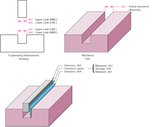
16 Terminology Limits of size is the largest acceptable size and the minimum acceptable size of a feature. The largest acceptable size is expressed as the maximum material condition (MMC) The smallest acceptable size is expressed as the least material condition (LMC).
17 Terminology Diameter symbol is the symbol which is placed preceding a numerical value indicating that the associated dimension shows the diameter of a circle. The symbol used is the Greek letter phi. Radius symbol is the symbol which is placed preceding a numerical value indicating that the associated dimension shows the radius of a circle. The radius symbol used is the capital letter R.
18
19 Terminology Datum is the theoretically exact point used as a reference for tabular dimensioning.
20 Basic Concepts Dimensions are used to describe the size and location of features on parts for manufacture. The basic criterion is, "What information is necessary to make the object?" Dimensions should not be excessive, either through duplication or dimensioning a feature more than one way.
21 Basic Concepts Size dimension might be the overall width of the part or the diameter of a drilled hole. Location dimension might be length from the edge of the object to the center of the drilled hole.
22 Basic Concepts Size dimensions Horizontal Vertical Diameter Radius Location and Orientation Horizontal Vertical Angle
23 Basic Concepts Rectangular coordinate dimensioning, a base line (or datum line) is established for each coordinate direction, and all dimensions specified with respect to these baselines. This is also known as datum dimensioning, or baseline dimensioning. All dimensions are calculated as X and Y distances from an origin point, usually placed at the lower left corner of the part.
24
25 Standard Practices- Placement Dimension placement depends on the space available between extension lines. When space permits, dimensions and arrows are placed between the extension lines.
26 Standard Practices- Spacing The minimum distance from the object to the first dimension is 10mm (3/8 inch). The minimum spacing between dimensions is 6mm (1/4 inch). There should be a visible gap between an extension line and the feature to which it refers. Extension lines should extend about 1mm (1/32 inch) beyond the last dimension line.
27 Standard Practices- Grouping Dimensions should be grouped for uniform appearance as shown.
28 Standard Practices- Staggering Where there are several parallel dimensions, the values should be staggered.
29 Standard Practices- Extension lines Extension lines are used to refer a dimension to a particular feature and are usually drawn perpendicular to the associated dimension line. Where space is limited, extension lines may be drawn at an angle.
30 Standard Practices- Extension lines Extension lines should not cross dimension lines, and should avoid crossing other extension lines whenever possible. When extension lines cross object lines or other extension lines, they are not broken. When extension lines cross or are close to arrowheads, they are broken for the arrowhead.
31 Standard Practices- Extension lines When the location of the center of a feature is being dimensioned, the center line of the feature is used as an extension line. When a point is being located by extension lines only, the extensions lines must pass through the point.
32 Standard Practices- Limited length or areas When it is necessary to define a limited length or area that is to receive additional treatment (such as the knurled portion of a shaft), the extent of the limits may be shown by a chain line. The chain line is drawn parallel to the surface being defined.
33 Standard Practices- Reading Direction All dimension and note text must be oriented to be read from the bottom of the drawing (relative to the drawing format). Placement of all text to be read from the bottom of the drawing is called unidirectional dimensioning. Aligned dimensions have text placed parallel to the dimension line with vertical dimensions read from the right of the drawing sheet.
34 Standard Practices- View Dimensioning Dimensions are to be kept outside of the boundaries of views of objects wherever practical. Dimensions may be place within the boundaries of objects in cases where extension or leader lines would be too long, or where clarity would be improved.
35 Standard Practices- Out-of- Scale Dimensions If it is necessary to include a dimension which is out of scale, the out of scale dimension text must be underlined.
36 Standard Practices- Repetitive Features The symbol X is used to indicate the number of times a feature is to be repeated. The number of repetitions, followed by the symbol X and a space precedes the dimension text.
37 Detail Dimensions Holes Diameters must be dimensioned with the diameter symbol preceding the numerical value. When holes are dimensioned with a leader line, the line must be radial. A radial line is one that passes through the center of a circle or arc if extended.
38 Chamfers Slotted holes
39 Keyseat and Keyway

40 Summary
41 Concentric circles
42 Arcs
43 Screw Threads
44 Grooves
45 Manufacturers gage
46 Dimension Techniques Contour Dimensioning contours or shapes of the object are dimensioned in their most descriptive view. For example, the radius of a arc would be dimensioned where it appears as an arc and not as a hidden feature.
47 Dimension Techniques Geometric Breakdown a part is to break the part into its geometric configurations.
48 Dimension Process
49 Dimension Guidelines The primary guideline is that of clarity and whenever two guidelines appear to conflict, the method which most clearly communicates the size information shall prevail. Every dimension must have an associated tolerance, and that tolerance must be clearly shown on the drawing. Avoid over-dimensioning a part. Double dimensioning of a feature is not permitted. Dimensions should be placed in the view which most clearly describes the feature being dimensioned.
50 Dimension Guidelines A minimum spacing between the object and dimensions and between dimensions must be maintained. A visible gap shall be placed between the end of extension lines and the feature to which they refer. Manufacturing methods should not be specified as part of the dimension unless no other method of manufacturing is acceptable. Placing dimensions within the boundaries of a view should be avoided whenever practicable.
51 Dimension Guidelines Dimensions for materials typically manufactured to gages or code numbers shall be specified by numerical values. Unless otherwise specified, angles shown on drawings are assumed to be 90 degrees. Dimensioning to hidden lines should be avoided whenever possible. Hidden lines are less clear than visible lines. The depth of blind, counterbored, or countersunk holes may be specified in a note along with the diameter.
52 Dimension Guidelines Diameters, radii, squares, counterbores, spotfaces, countersinks, and depth should be specified with the appropriate symbol preceding the numerical value. Leader lines for diameters and radii should be radial lines.
53 Tolerancing Tolerance is the total amount a dimension may vary and is the difference between the upper (maximum) and lower (minimum) limits. Tolerances are used to control the amount of variation inherent in all manufactured parts. In particular, tolerances are assigned to mating parts in an assembly.
54 Tolerancing One of the great advantages of using tolerances is that it allows for interchangeable parts, thus permitting the replacement of individual parts. Tolerances are used in production drawings to control the manufacturing process more accurately and control the variation between parts.

55 Tolerancing Tolerance representation Direct limits or as tolerance values applied directly to a dimension. Geometric tolerances Notes referring to specific condition.
56 Tolerancing Tolerance representation Plus/Minus
57 Tolerancing Important terms Nominal size a dimension used to describe the general size usually expressed in common fractions. Basic size the theoretical size used as a starting point for the application of tolerances. Actual size the measured size of the finished part after machining.
58 Tolerancing Important terms Limits the maximum and minimum sizes shown by the toleranced dimension. Allowance is the minimum clearance or maximum interference between parts. Tolerance is the total variance in a dimension which is the difference between the upper and lower limits. The tolerance of the slot in Figure is.004" and the tolerance of the mating part is.002".
59 Tolerancing Important terms Maximum material condition (MMC) is the condition of a part when it contains the most amount of material. The MMC of an external feature such as a shaft is the upper limit. The MMC of an internal feature such as a hole is the lower limit.
60 Tolerancing Important terms Least material condition (LMC) is the condition of a part when it contains the least amount of material possible. The LMC of an external feature is the lower limit of the part. The LMC of an internal feature is the upper limit of the part.
61 Tolerancing
62 Tolerancing Fit types Clearance fit occurs when two toleranced mating parts will always leave a space or clearance when assembled. Interference fit occurs when two toleranced mating parts will always interfere when assembled. Transition fit occurs when two toleranced mating parts will sometimes be an interference fit and sometimes be a clearance fit when assembled.
63 Tolerancing
64 Tolerancing
65 Tolerancing Metric Limits and Fits Basic size Deviation Upper Deviation Lower Deviation Fundamental Deviation
66 Tolerancing Tolerance Tolerance zone International tolerance grade Hole basis Shaft basis
67 Tolerancing Symbols and Definitions Methods

68 Tolerancing Standard Hole basis table; limits
69 Tolerancing Hole basis system; fits
70 Tolerancing Shaft basis system; fits

71
72 Tolerancing Standard Precision Fit; English Units Running and Sliding (RC) Clearance Locational (LC) Transition Locational (LT) Interference Locational (LN) Force and Shrinks (FN)
73 Geometric Dimensioning and Tolerancing GDT is a method of defining parts based on how they function, using standard ASME/ANSI symbols.
74 Geometric Dimensioning and Tolerancing Within the last 15 years there has been considerable interest in GDT, in part because of the increased popularity of statistical process control. This control process, when combined with GDT, helps reduce or eliminate inspection of features on the manufactured object. The flipside is that the part must be toleranced very efficiently; this is where GDT comes in.
75 Geometric Dimensioning and Tolerancing Another reason for the increased popularity of GDT is the rise of worldwide standards, such as ISO 9000, which require universally understood and accepted methods of documentation.
76 GDT-Symbols
77 GDT Feature control frames

78 GDT MMC/LMC Datums Geometric Controls Form Orientation Position
79 GDT Forms Straightness Line element Axis
80 GDT Forms Circularity
81 GDT Forms Flatness
82 GDT Forms Cylindricity
83 GDT Orientation Parallelism
84 GDT Orientation Perpendicularity
85 GDT Orientation Angularity
86 GDT Orientation Line profile
87 GDT Orientation Surface profile
88 GDT Location Concentricity
89 GDT Location Runout
90 GDT Location Position
91 GDT Location Position
92 GDT Tolerance Calculation Floating fastener tolerancing is used to confirm that loose bolts, screws or other fasteners have the standard clearance in their holes. Fixed fastener tolerancing is measured the same as with floating fasteners except that the fastener is already fixed/located on one of the mating parts and the tolerance is now divided between the parts.
93 GDT Tolerance Calculation Hole diameter tolerancing is used to calculate the MMC of the hole.
94 GDT Design Application Five-Step Isolate and define the functions of the features/part. Prioritize the functions. Identify the datum reference frame based on functional priorities. Select the proper control(s). Calculate the tolerance values.
ASME Geometric Dimensioning and Tolerancing Professional Certification
 ASME Geometric Dimensioning and Tolerancing Professional Certification Applicant Information STATEMENT OF POLICY ON THE USE OF ASME GDTP SYMBOLS AND AUTHORIZATION IN ADVERTISING ASME has established procedures
Section. Tolerances. Aluminum Extrusion Manual. 4th Edition
 Section 8 Tolerances Aluminum Extrusion Manual 4th Edition Section 8 How straight is straight enough? How flat is flat enough? How uniform must a wall thickness be in order to be acceptable? These are
Technical Drawing. MEC1000 Spring 2006 Instructor: David Anderson
 Technical Drawing MEC1000 Spring 2006 Instructor: David Anderson Topics Drawing Views Drawing Standards Best Practices Creating Drawings in SolidWorks Spring 2006 MEC1000 Technical Drawing - D. Anderson
Technical Drawing Specifications Resource A guide to support VCE Visual Communication Design study design 2013-17
 A guide to support VCE Visual Communication Design study design 2013-17 1 Contents INTRODUCTION The Australian Standards (AS) Key knowledge and skills THREE-DIMENSIONAL DRAWING PARALINE DRAWING Isometric
CATIA Functional Tolerancing & Annotation TABLE OF CONTENTS
 TABLE OF CONTENTS Introduction...1 Functional Tolerancing and Annotation...2 Pull-down Menus...3 Insert...3 Functional Tolerancing and Annotation Workbench...4 Bottom Toolbar Changes...5 3D Grid Toolbar...5
DWG 001. Blueprint Reading. Line Standards Drawing Symbols. Instructor Guide
 DWG 001 Blueprint Reading Line Standards Drawing Symbols Instructor Guide Module Purpose Introduction The purpose of the Blueprint Reading modules is to introduce students to production drawings and blueprint
Standards for Working Drawings
 Standards for Working Drawings 27 August 2013 Department of Mechanical and Mechatronic Engineering and Sustainable Manufacturing California State University, Chico Chico, California 95929-0789 Contents
ISO 1101 Geometrical product specifications (GPS) Geometrical tolerancing Tolerances of form, orientation, location and run-out
 Geometrical tolerancing Tolerances of form, orientation, location and run-out") INTERNATIONAL STANDARD ISO 1101 Third edition 2012-04-15 Geometrical product specifications (GPS) Geometrical tolerancing Tolerances of form, orientation, location and run-out Spécification géométrique
INTERNATIONAL STANDARD ISO 1101 Third edition 2012-04-15 Geometrical product specifications (GPS) Geometrical tolerancing Tolerances of form, orientation, location and run-out Spécification géométrique
Working Drawing and Assemblies. Chapter 10
 Working Drawing and Assemblies Chapter 10 Objectives 1.Define working drawings. 2. Describe how working drawings are used in industry. 3. List the major components of a complete set of working drawings.
CATIA Drafting TABLE OF CONTENTS
 TABLE OF CONTENTS Introduction...1 Drafting...2 Drawing Screen...3 Pull-down Menus...4 File...4 Edit...5 View...6 Insert...7 Tools...8 Drafting Workbench...9 Views and Sheets...9 Dimensions and Annotations...10
DRAFTING MANUAL. Gears (Bevel and Hypoid) Drafting Practice
 Drafting Practice") Page 1 1.0 General This section provides the basis for uniformity in engineering gears drawings and their technical data for gears with intersecting axes (bevel gears), and nonparallel, nonintersecting
Page 1 1.0 General This section provides the basis for uniformity in engineering gears drawings and their technical data for gears with intersecting axes (bevel gears), and nonparallel, nonintersecting
American National, Unified Screw Threads
 C h a p t e r 9 American National, Unified Screw Threads In this chapter, you will learn the following to World Class standards:! Why Use Fasteners! The Text Designation for the Unified National Thread!
Removing chips is a method for producing plastic threads of small diameters and high batches, which cause frequent failures of thread punches.
 Plastic Threads Technical University of Gabrovo Yordanka Atanasova Threads in plastic products can be produced in three ways: a) by direct moulding with thread punch or die; b) by placing a threaded metal
Traditional Drawing Tools
 Engineering Drawing Traditional Drawing Tools DRAWING TOOLS DRAWING TOOLS 1. T-Square 2. Triangles DRAWING TOOLS HB for thick line 2H for thin line 3. Adhesive Tape 4. Pencils DRAWING TOOLS 5. Sandpaper
Engineering & Design: Geometric Dimensioning
 Section Contents NADCA No. Format Page 1 Introduction -2 S E C T I O N 2 What is GD&T? -2 3 Why Should GD&T be Used? -3 4 Datum Reference Frame -4 4.1 Primary, Secondary, Tertiary Features & Datums -4
SolidWorks TolAnalyst Frequently Asked Questions
 SolidWorks TolAnalyst Frequently Asked Questions Q: What is tolerance stack-up analysis? A: A Tolerance Stack-Up Analysis is an analysis used by designers and engineers to determine if an assembly of parts
UNITED STATES CUTTING TOOL INSTITUTE Product Groupings for Standards Activities CUTTING TOOL PRODUCTS
 CUTTING TOOL PRODUCTS 1. BORING ISO 5609 Boring bars for indexable inserts Dimensions ISO 6261 Boring bars (tool holders with cylindrical shank) for indexable inserts Designation JIS B 4128 Boring bars
Freehand Sketching. Sections
 3 Freehand Sketching Sections 3.1 Why Freehand Sketches? 3.2 Freehand Sketching Fundamentals 3.3 Basic Freehand Sketching 3.4 Advanced Freehand Sketching Key Terms Objectives Explain why freehand sketching
Product Design (Part 4)
") Product Design (Part 4) Engineering Drawing Chapter 16 Drawing Standards Line conventions and lettering- ANSI/ASME Y14.2M-1992 Multiview and sectional view drawings- ANSI/ASME Y14.3M-1994 Pictorial drawing-ansi/asme
Product Design (Part 4) Engineering Drawing Chapter 16 Drawing Standards Line conventions and lettering- ANSI/ASME Y14.2M-1992 Multiview and sectional view drawings- ANSI/ASME Y14.3M-1994 Pictorial drawing-ansi/asme
PIPING DRAWINGS BASICS N.P.TODKAR
 PIPING DRAWINGS BASICS N.P.TODKAR There are two types of views used in the piping drawings: a) Orthographic- Plans and Elevations b) Pictorial - Isometric Views Piping layout is developed in both plan
ABERLINK 3D MKIII MEASUREMENT SOFTWARE
 ABERLINK 3D MKIII MEASUREMENT SOFTWARE PART 1 (MANUAL VERSION) COURSE TRAINING NOTES ABERLINK LTD. EASTCOMBE GLOS. GL6 7DY UK INDEX 1.0 Introduction to CMM measurement...4 2.0 Preparation and general hints
PARAMETRIC MODELING. David Rosen. December 1997. By carefully laying-out datums and geometry, then constraining them with dimensions and constraints,
 1 of 5 11/18/2004 6:24 PM PARAMETRIC MODELING David Rosen December 1997 The term parametric modeling denotes the use of parameters to control the dimensions and shape of CAD models. Think of a rubber CAD
SCREW THREADS C H A P T E R 17
 C H A P T E R 17 SCREW THREADS Screw threads are of prime importance in machine drawing. It is a functional element used as temporary fasteners such as bolt, stud, nut and screw etc. These are constructed
Common Mechanical Engineering Terms
 Common Mechanical Engineering Terms Ball and Detent (n) A simple mechanical arrangement used to hold a moving part in a temporarily fixed position relative to another part. The ball slides within a bored
Fastener Handout. Introduction: Engineering Design Representation 2. Threads 2. Local Notes (callouts) 8. Threaded Mechanical Fasteners 13
 8. Threaded Mechanical Fasteners 13") Fastener Handout Introduction: Engineering Design Representation 2 Threads 2 Effect of thread angle on strength: 3 Standardization of Threads: 4 Descriptions of the Thread Series: 4 Class fit: 5 Specification
Fastener Handout Introduction: Engineering Design Representation 2 Threads 2 Effect of thread angle on strength: 3 Standardization of Threads: 4 Descriptions of the Thread Series: 4 Class fit: 5 Specification
West Sound Technical Skills Center 101 National Avenue N. Bremerton WA 98312
 West Sound Technical Skills Center 101 National Avenue N. Bremerton WA 98312 Instructor: Tony Sharpe Phone: 360-473-0585 Fax: 360-478-5090 Email: tony.sharpe@bremertonschools.org Hours: 7:30 a.m. 3:00
DEUTSCHE NORM June 1998. Forms and dimensions of undercuts
 DEUTSCHE NORM June 1998 Forms dimensions of s { 509 ICS 01.100.20; 25.020 Descriptors: Undercuts, types, dimensions, technical drawings. Supersedes August 1966 edition. Freistiche Formen, Maße In keeping
Fastener Handout. Introduction: Engineering Design Representation 2. Threads 2. Local Notes (callouts) 8. Threaded Mechanical Fasteners 13
 8. Threaded Mechanical Fasteners 13") Fastener Handout Introduction: Engineering Design Representation 2 Threads 2 Effect of thread angle on strength: 3 Standardization of Threads: 4 Descriptions of the Thread Series: 4 Class fit: 5 Specification
Fastener Handout Introduction: Engineering Design Representation 2 Threads 2 Effect of thread angle on strength: 3 Standardization of Threads: 4 Descriptions of the Thread Series: 4 Class fit: 5 Specification
AISI CHEMICAL COMPOSITION LIMITS: Nonresulphurized Carbon Steels
 AISI CHEMICAL COMPOSITION LIMITS: Nonresulphurized Carbon Steels AISI No. 1008 1010 1012 1015 1016 1017 1018 1019 1020 1021 1022 1023 1024 10 1026 1027 1029 10 1035 1036 1037 1038 1039 10 1041 1042 1043
WORKBOOK MODELING OF MULTI- MEMBER MACHINES
 WORKBOOK MODELING OF MULTI- MEMBER MACHINES LUBLIN 2014 0 Author: Mirosław Ferdynus Desktop publishing: Mirosław Ferdynus Technical editor: Mirosław Ferdynus Figures: Mirosław Ferdynus Cover and graphic
TABLE OF CONTENTS. INTRODUCTION... 5 Advance Concrete... 5 Where to find information?... 6 INSTALLATION... 7 STARTING ADVANCE CONCRETE...
 Starting Guide TABLE OF CONTENTS INTRODUCTION... 5 Advance Concrete... 5 Where to find information?... 6 INSTALLATION... 7 STARTING ADVANCE CONCRETE... 7 ADVANCE CONCRETE USER INTERFACE... 7 Other important
Introduction to CATIA V5
 Introduction to CATIA V5 Release 16 (A Hands-On Tutorial Approach) Kirstie Plantenberg University of Detroit Mercy SDC PUBLICATIONS Schroff Development Corporation www.schroff.com www.schroff-europe.com
SAMPLE TEST PAPER - I
 SCHEME E SAMPLE TEST PAPER - I Course Name : Mechanical Engineering Group Course Code : AE/PG/PT/ME/MH/FE Semester : Third Subject : Mechanical Engineering Drawing 12042 Time : 90 Minutes Marks: 25 Instruction:
Modeling Curved Surfaces
 Modeling Cylindrical and Curved Theory Views of Cylinders Contour Lines Extruded Surfaces Revolved Surfaces & Cutouts Profile Shape Axis of Revolution Swept Surfaces & Cutouts Profile Shape Path Curves
Sectional drawings cutting plane
 Section Views Section Views The technique called section views is used to improve the visualization of new designs, clarify multiview drawings and facilitate the dimensioning of drawings. For mechanical
Gate Leg Drop Leaf Table Plans
 Preparing the table top blanks: Cut and glue enough 3/4 stock to make three panels 40 long by 24 wide (they will be cut to final size at a later time). While the glue dries we will work on the legs. Preparing
DRAWING INSTRUMENTS AND THEIR USES
 Chapter - A DRAWING INSTRUMENTS AND THEIR USES Drawing Instruments are used to prepare neat and accurate Drawings. To a greater extent, the accuracy of the Drawings depend on the quality of instruments
OD1641 PRINCIPLES OF DRAFTING AND SHOP DRAWINGS
 SUBCOURSE OD1641 EDITION 8 PRINCIPLES OF DRAFTING AND SHOP DRAWINGS US ARMY REPAIR SHOP TECHNICIAN WARRANT OFFICER ADVANCED CORRESPONDENCE COURSE MOS/SKILL LEVEL: 441A PRINCIPLES OF DRAFTING AND SHOP
DRAFTING. Prepared by:
 GTRI MACHINE SERVICES DRAFTING STANDARDS Prepared by: Machine Services Department Georgia Tech Research Institute December 16, 2011 Copyright 2011 Georgia Tech Research Corporation. Alll rights reserved.
An Overview of ASME Y14.41 2003
 An Overview of ASME Y14.41 2003 August 5, 2003 Alex Krulikowski 1 Introduction Alex Krulikowski Manager of Standards and GD&T COE Embedded GD&T implementation project at GM Powertrain Chair of ASME Y14.41
ME 111: Engineering Drawing
 ME 111: Engineering Drawing Lecture # 14 (10/10/2011) Development of Surfaces http://www.iitg.ernet.in/arindam.dey/me111.htm http://www.iitg.ernet.in/rkbc/me111.htm http://shilloi.iitg.ernet.in/~psr/ Indian
INSTRUCTIONS FOR CHAIN LINK INSTALLATION Chain Link fence & Posts Meshdirect.co.uk
 INSTRUCTIONS FOR CHAIN LINK INSTALLATION Chain Link fence & Posts Meshdirect.co.uk This guide explains how to correctly install our chain link fencing and post system. The guide provides details of the
SolidWorks Tutorial 3 MAGNETIC BLOCK
 SolidWorks Tutorial 3 MAGNETIC BLOCK Magnetic Block In this exercise you will make a magnetic block. To do so, you will create a few parts, which you will assemble. You will learn the following new applications
GEAROLOGY 4-1 WORMS AND WORM GEARS WORMS AND WORM GEARS
 GEAROLOGY 4-1 4 4-2 GEAROLOGY COMMON APPLICATIONS: Worm and worm gear sets are used in many, everyday products including: electrical mixers, hubometers, right Now that you have an understanding of two
Introduction to Autodesk Inventor for F1 in Schools
 Introduction to Autodesk Inventor for F1 in Schools F1 in Schools Race Car In this course you will be introduced to Autodesk Inventor, which is the centerpiece of Autodesk s digital prototyping strategy
Screw Thread Design. Rev. 3-4-09
 Screw Thread Design Screw Thread Fundamentals A screw thread is defined as a ridge of uniform section in the form of a helix on either the external or internal surface of a cylinder. Internal threads refer
Designing and Drawing a Sprocket Visualizing ideas through the creation of CAD solid models is a key engineering skill.
 05 Webster St. Hanover Massachusetts 0339 Tel. 78 878 5 Fax 78 878 6708 Designing and Drawing a Sprocket Visualizing ideas through the creation of CAD solid models is a key engineering skill. The following
Home"" """"> ar.cn.de.en.es.fr.id.it.ph.po.ru.sw
 Home"" """"> ar.cn.de.en.es.fr.id.it.ph.po.ru.sw Milling of Grooves, Elongated Slots and Break-throughs - Course: Techniques for machining of material. Trainees' handbook of lessons (Institut fr Berufliche
Engineering & Design: Coordinate Dimensioning
 s e c t i o n Section Contents NADCA No. Format Page Frequently Asked Questions (FAQ) -2 1 Introduction -2 2 Section Objectives -3 3 Standard and Precision Tolerances -3 4 Production Part Technologies
MECHANICAL PRINCIPLES HNC/D MOMENTS OF AREA. Define and calculate 1st. moments of areas. Define and calculate 2nd moments of areas.
 MECHANICAL PRINCIPLES HNC/D MOMENTS OF AREA The concepts of first and second moments of area fundamental to several areas of engineering including solid mechanics and fluid mechanics. Students who are
Reflection and Refraction
 Equipment Reflection and Refraction Acrylic block set, plane-concave-convex universal mirror, cork board, cork board stand, pins, flashlight, protractor, ruler, mirror worksheet, rectangular block worksheet,
Making 3D Threads in Feature Based Solid Modelers
 Making 3D Threads in Feature Based Solid Modelers THREAD BASICS Making true geometric threads in feature-based solid modelers is a fairly straightforward process and can be handled using several different
VCE VET ENGINEERING STUDIES
 Victorian Certificate of Education 2013 SUPERVISOR TO ATTACH PROCESSING LABEL HERE STUDENT NUMBER Letter Figures Words VCE VET ENGINEERING STUDIES Written examination Section Wednesday 20 November 2013
Chapter 3 Installing Over-the-Post Railing on an L-Shaped Stair
 49 Chapter 3 Installing Over-the-Post Railing on an L-Shaped Stair In this chapter: The Over-the-Post Balustrade System Determining the Rail Centerline Using Rail Bolts Making a Pitch Block Laying Out
DESIGN BY: ARCH. GIUSEPPE INZITARI
 DESIGN BY: ARCH. GIUSEPPE INZITARI 218 FOR HIGH THICKNESS FROM 12 TO 17.5 MM - GIUMAX GIUMAX 9500 Page 220 GIUMAX 8500 Page 227 ROLLERS Page 233 GIUMAX 4500 Page 236 GIUMAX 6500 Page 244 FROM 8 TO 12 MM
OD 1401 9 PRECISION MEASURING INSTRUMENTS
 SUBCOURSE EDITION OD 1401 9 PRECISION MEASURING INSTRUMENTS PRECISION MEASURING INSTRUMENTS SUBCOURSE OD1401 EDITION 9 Unites States Army Combined Arms Support Command Fort Lee, VA 23801-1809 5 CREDIT
Force measurement. Forces VECTORIAL ISSUES ACTION ET RÉACTION ISOSTATISM
 Force measurement Forces VECTORIAL ISSUES In classical mechanics, a force is defined as "an action capable of modifying the quantity of movement of a material point". Therefore, a force has the attributes
Creating Drawings in Pro/ENGINEER
 6 Creating Drawings in Pro/ENGINEER This chapter shows you how to bring the cell phone models and the assembly you ve created into the Pro/ENGINEER Drawing mode to create a drawing. A mechanical drawing
Wallingford Public Schools - HIGH SCHOOL COURSE OUTLINE
 Wallingford Public Schools - HIGH SCHOOL COURSE OUTLINE Course Title: Computer Aided Drafting & Design Course Number: 7163 Department: Career and Technical Education Grade(s): 9-12 Level(s): Academic Credit:
RULE 1. The Field of Play
 RULE 1 The Field of Play 1.1 Dimensions 1.1.1 The field of play shall be rectangular, the width of which shall not be more than 75 yards [68.58 m] or less than 70 yards [64.01 m] and shall not exceed the
Geometric Optics Converging Lenses and Mirrors Physics Lab IV
 Objective Geometric Optics Converging Lenses and Mirrors Physics Lab IV In this set of lab exercises, the basic properties geometric optics concerning converging lenses and mirrors will be explored. The
The GED math test gives you a page of math formulas that
 Math Smart 643 The GED Math Formulas The GED math test gives you a page of math formulas that you can use on the test, but just seeing the formulas doesn t do you any good. The important thing is understanding
IMPLEMENTATION OF MS ACCESS SOFTWARE FOR CASING-CLASS MANUFACTURING FEATURES SAVING
 constructional data, database, casing-class part, MS Access Arkadiusz GOLA *, Łukasz SOBASZEK ** IMPLEMENTATION OF MS ACCESS SOFTWARE FOR CASING-CLASS MANUFACTURING FEATURES SAVING Abstract Manufacturing
Chapter 1. Creating Sketches in. the Sketch Mode-I. Evaluation chapter. Logon to www.cadcim.com for more details. Learning Objectives
 Chapter 1 Creating Sketches in Learning Objectives the Sketch Mode-I After completing this chapter you will be able to: Use various tools to create a geometry. Dimension a sketch. Apply constraints to
ECONOMIC COMMISSION OF EUROPE (ECE) BRANDING
 BRANDING") Much like the U.S. Department of Transportation, The Economic Commission of Europe, or ECE, regulates the manufacturing of vehicle components. To receive ECE branded approval, tires must meet set standards
Much like the U.S. Department of Transportation, The Economic Commission of Europe, or ECE, regulates the manufacturing of vehicle components. To receive ECE branded approval, tires must meet set standards
Mechanical Measurement and Inspection Techniques
 Unit 19: Mechanical Measurement and Inspection Techniques Unit code: QCF Level 3: Credit value: 10 Guided learning hours: 60 Aim and purpose J/600/0269 BTEC National This unit will give learners a broad
Parametric Technology Corporation. Pro/ENGINEER Wildfire 4.0 Tolerance Analysis Extension Powered by CETOL Technology Reference Guide
 Parametric Technology Corporation Pro/ENGINEER Wildfire 4.0 Tolerance Analysis Extension Powered by CETOL Technology Reference Guide Copyright 2007 Parametric Technology Corporation. All Rights Reserved.
Radius Compensation G40, G41, & G42 (cutter radius compensation for machining centers, tool nose radius compensation for turning centers)
") Radius Compensation G40, G41, & G42 (cutter radius compensation for machining centers, tool nose radius compensation for turning centers) These features are commonly well covered in most basic CNC courses.
Radius Compensation G40, G41, & G42 (cutter radius compensation for machining centers, tool nose radius compensation for turning centers) These features are commonly well covered in most basic CNC courses.
Pro/ENGINEER Wildfire 4.0 Basic Design
 Introduction Datum features are non-solid features used during the construction of other features. The most common datum features include planes, axes, coordinate systems, and curves. Datum features do
Router Table Plans. www.bobsplans.com
 www.bobsplans.com Router Table Plans Increase the capabilities of your router with this weekend project. Features a sliding fence with EZ-Mount clamps. These clamps are simple to make and grip tightly
DECIPHERING WELD SYMBOLS
 DECIPHERING WELD SYMBOLS When welds are specified on engineering and fabrication drawings, a cryptic set of symbols issued as a sort of shorthand for describing the type of weld, its size, and other processing
SHOP NOTES METAL SHAPER FOR YOUR SHOP
 SHOP NOTES METAL SHAPER FOR YOUR SHOP A METAL SHAPER is indispensable for certain machining operations where flat surfaces must be produced within very close limits, such as machining flats on castings,
Building an Off-Center Fixture for Turning Pendants
 Building an Off-Center Fixture for Turning Pendants Turning a pendant off-center with most available metal pendant chucks means that you will have a significant amount of mass off center, which will limit
16 Circles and Cylinders
 16 Circles and Cylinders 16.1 Introduction to Circles In this section we consider the circle, looking at drawing circles and at the lines that split circles into different parts. A chord joins any two
Specification for Rotary Drill Stem Elements
 Addendum 1 March 2007 Effective Date: September 1, 2007 Specification for Rotary Drill Stem Elements ANSI/API SPECIFICATION 7-1 FIRST EDITION, MARCH 2006 EFFECTIVE DATE: SEPTEMBER 2006 ISO 10424-1:2004
SPECIFICATION Aluminum Module Frames. Allowed anodization before fabrication for clear frames.
 SPECIFICATION Allowed anodization before fabrication for clear frames. Page 2 of 9 1. SCOPE 1.1. This document provides general requirements for aluminum frames used in the assembly of photovoltaic modules.
Sheet Metal Bending. By- Prem Mahendranathan
 Sheet Metal Bending By- BENDING n Bending is a manufacturing process by which a metal can be deformed by plastically deforming the material and changing its shape n Deformation about one axis PROFILES
Basic AutoSketch Manual
 Basic AutoSketch Manual Instruction for students Skf-Manual.doc of 3 Contents BASIC AUTOSKETCH MANUAL... INSTRUCTION FOR STUDENTS... BASIC AUTOSKETCH INSTRUCTION... 3 SCREEN LAYOUT... 3 MENU BAR... 3 FILE
Introduction to Autodesk Inventor for F1 in Schools
 F1 in Schools race car Introduction to Autodesk Inventor for F1 in Schools In this course you will be introduced to Autodesk Inventor, which is the centerpiece of Autodesk s Digital Prototyping strategy
BUILD A TABLETOP LOOM
 BUILD A TABLETOP LOOM From 1" x 2" stock (actual 3/4" x 1"1/2) cut: 4 pieces 15" long 4 pieces 5"1/2 long Use the above to make 2 frames for the front and back of the loom. From 1" x 4" stock (actual 3/4"
Milling Milling milling cutter milling machines 1
 Milling Milling is a basic machining process by which a surface is generated progressively by the removal of chips from a workpiece as it is fed to a rotating cutter in a direction perpendicular to the
KITCHENS. Tip PAGE 1 FITTING YOUR KITCHEN GUIDE. How to mark out a kitchen. Tools required for installing a kitchen STEP ONE STEP TWO STEP THREE
 FITTING YOUR KITCHEN GUIDE How to mark out a kitchen PAGE 1 Before starting on the installation, measure 870mm from the lowest point of the floor and mark a datum line around the room to indicate where
Lathe Milling Attachment
 Lathe Milling Attachment By L C. MASON BY CLEVERLY stacking cold-rolled flat stock together, T-slots and slide for this lathe milling attachment are made without costly machinery. In fact, only two tools,
Basic 2D Design Be sure you have the latest information!
 Basic 2D Design mastercam x getting started tutorials Basic 2D Design December 2011 Be sure you have the latest information! Information might have been changed or added since this document was published.
Splined connections with involute splines based on reference diameters Part 1: Principles
 March 2006 DIN 5480-1 Splined connections with involute splines based on reference diameters Part 1: Principles Passverzahnungen mit Evolventenflanken und Bezugsdurchmesser Teil 1: Grundlagen Supersedes
DSM http://www.dsmmfg.com 1 (800) 886-6376
 886-6376") DESIGN GUIDE FOR BENT SHEET METAL This guide discusses how the bends are made, what thicknesses of sheet metal are commonly used, recommended bend radius to use when modeling the part, some practical limits
DESIGN GUIDE FOR BENT SHEET METAL This guide discusses how the bends are made, what thicknesses of sheet metal are commonly used, recommended bend radius to use when modeling the part, some practical limits
Solid shape molding is not desired in injection molding due to following reasons.
 PLASTICS PART DESIGN and MOULDABILITY Injection molding is popular manufacturing method because of its high-speed production capability. Performance of plastics part is limited by its properties which
AC 2012-4265: PROMOTING AWARENESS IN MANUFACTURING STU- DENTS OF
 AC 2012-4265: PROMOTING AWARENESS IN MANUFACTURING STU- DENTS OF Dr. Merwan B. Mehta, East Carolina University Merwan Mehta, Ph.D., is Associate Professor at East Carolina University, Greenville, N.C.,
Brown Hills College of Engineering & Technology Machine Design - 1. UNIT 1 D e s i g n P h i l o s o p h y
 UNIT 1 D e s i g n P h i l o s o p h y Problem Identification- Problem Statement, Specifications, Constraints, Feasibility Study-Technical Feasibility, Economic & Financial Feasibility, Social & Environmental
Technical Regulations 2015-2016
 F1 in Schools - 2014 World Finals Technical Regulations Technical Regulations 2015-2016 2013 - F1 in Schools Ltd. Page 1 of 27 3 September 2015 CONTENTS PREFACE SUMMARY OF MAIN REVISIONS FROM 2013 REGULATIONS...
Chapter 6 Machining Center Carbide Insert Fundamentals
 This sample chapter is for review purposes only. Copyright The Goodheart-Willcox Co., Inc. All rights reserved. N10G20G99G40 N20G96S800M3 N30G50S4000 N40T0100M8 N50G00X3.35Z1.25T0101 N60G01X3.25F.002 N70G04X0.5
SpaceClaim Introduction Training Session. A SpaceClaim Support Document
 SpaceClaim Introduction Training Session A SpaceClaim Support Document In this class we will walk through the basic tools used to create and modify models in SpaceClaim. Introduction We will focus on:
DECKING INSTALLATION, CARE & MAINTENANCE INSTRUCTIONS. 866.729.2378 MOISTURESHIELD.COM limited lifetime warranty 866.729.2378 WWW.MOISTURESHIELD.
 DECKING INSTALLATION, CARE & MAINTENANCE INSTRUCTIONS 866.729.2378 MOISTURESHIELD.COM limited lifetime warranty Welcome To The Even Greater Outdoors. Congratulations on choosing MoistureShield for your
TECHNICAL DRAWING (67)
") TECHNICAL DRAWING (67) (Candidates offering Technical Drawing Applications are not eligible to offer Technical Drawing.) Aims: 1. To develop competence among the students to pursue technical courses like
TECHNICAL DRAWING (67) (Candidates offering Technical Drawing Applications are not eligible to offer Technical Drawing.) Aims: 1. To develop competence among the students to pursue technical courses like
Fasteners and screw threads
 ISO Standards Handbook: Fasteners and screw threads Volume 2: Product standards Contents Part 3 : Product standards 2001, Ed. 5, 1094 p., ISBN 92-67-10345-8 3.1 External drive hexagon head bolts and screws
Technical Data. 7. Bearing Fits. 7.1 Interference. 7.2 Calculation of interference F B LLLLLLLLL( A-54
 Technical Data 7. Bearing Fits 7.1 Interference For rolling s the rings are fixed on the or in the housing so that slip or movement does not occur between the mated surface during operation or under. This
CAD / CAM Dr. P. V. Madhusuthan Rao Department of Mechanical Engineering Indian Institute of Technology, Delhi Lecture No. # 12 Reverse Engineering
 CAD / CAM Dr. P. V. Madhusuthan Rao Department of Mechanical Engineering Indian Institute of Technology, Delhi Lecture No. # 12 Reverse Engineering So what we will do in today s lecture is basically take