HOME GYM. Model. Retain This Manual for Reference OWNER'S MANUAL.
|
|
|
- Bryce McGee
- 9 years ago
- Views:
Transcription
1 NOTE: Please read all instructions carefully before using this product Table of Contents Safety Notice HOME GYM Hardware Identifier Assembly Instruction Parts List Warranty Ordering Parts Model Retain This Manual for Reference OWNER'S MANUAL Please contact HUNTER LEISURE AUSTRALIA Should any questions arise at Warranty Service: If you require warranty service, please do not return the gym to the store. Contact Hunter Leisure Australia on

2 TABLE OF CONTENTS BEFORE YOU BEGIN... 2 IMPORTANT SAFETY NOTICES... 3 HARDWARE PACK ASSEMBLY INSTRUCTIONS... 6 WEIGHT RESISTANCE CHART...25 PARTS LIST.. 26 WARRANTY ORDERING PARTS BEFORE YOU BEGIN Thank you for selecting the HOME GYM by HYPER-EXTENSION. For your safety and benefit, read this manual carefully before using the machine. As a manufacturer, we are committed to provide you complete customer satisfaction. If you have any questions, or find there are missing or damaged parts, we guarantee you complete satisfaction through direct assistance from our factory. To avoid unnecessary delays, please call our TOLL-FREE customer service number. Our Customer Service Agents will provide immediate assistance to you. Toll-Free Customer Service Number Mon. - Fri. 9 a.m. - 5 p.m. AEST

3 IMPORTANT SAFETY NOTICE PRECAUTIONS This exercise machine is built for optimum safety. However, certain precautions apply whenever you operate a piece of exercise equipment. Be sure to read the entire manual before you assemble or operate your machine. In particular, note the following safety precautions: 1. Keep children and pets away from the machine at all times. DO NOT leave children unattended in the same room with the machine. 2. Only one person at a time should use the machine. 3. If the user experiences dizziness, nausea, chest pain, or any other abnormal symptoms, STOP the workout at once. CONSULT A PHYSICIAN IMMEDIATELY. 4. Position the machine on a clear, leveled surface. DO NOT use the machine near water or outdoors. 5. Keep hands away from all moving parts. 6. Always wear appropriate workout clothing when exercising. DO NOT wear robes or other clothing that could become caught in the machine. Running or aerobic shoes are also required when using the machine. 7. Use the machine only for its intended use as described in this manual. DO NOT use attachments not recommended by the manufacturer. 8. Do not place any sharp object around the machine. 9. Disabled person should not use the machine without a qualified person or physician in attendance. 10. Before using the machine to exercise, always do stretching exercises to properly warm up. 11. Never operate the machine if the machine is not functioning properly. WARNING: BEFORE BEGINNING ANY EXERCISE PROGRAM, CONSULT YOUR PHYSICIAN. THIS IS ESPECIALLY IMPORTANT FOR INDIVIDUALS OVER THE AGE OF 35 OR PERSONS WITH PRE-EXISTING HEALTH PROBLEMS. READ ALL INSTRUCTIONS BEFORE USING ANY FITNESS EQUIPMENT. HYPER-EXTENSION LIMITED ASSUMES NO RESPONSIBILITY FOR PERSONAL INJURY OR PROPERTY DAMAGE SUSTAINED BY OR THROUGH THE USE OF THIS PRODUCT. SAVE THESE INSTRUCTIONS.

4 HARDWARE PACK
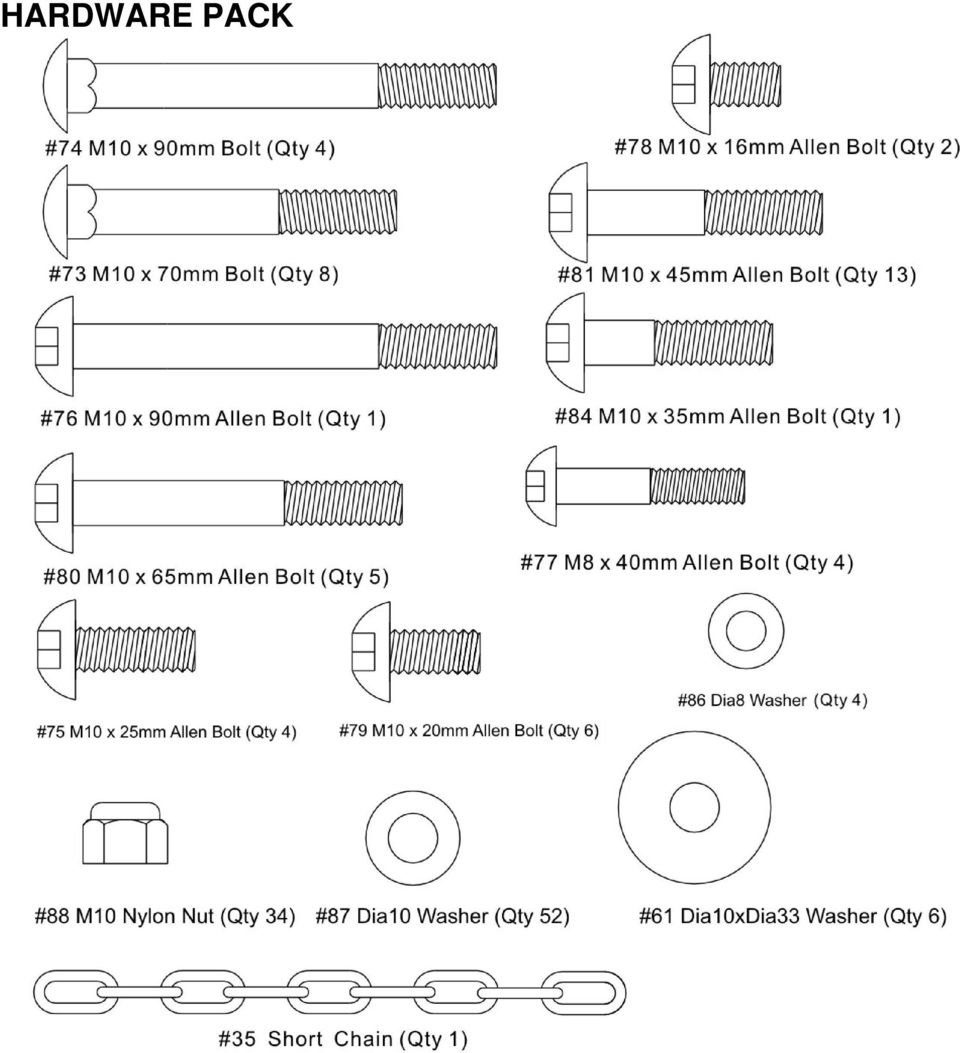
5 HARDWARE PACK

6 ASSEMBLY INSTRUCTION Tools Required Assembling the Machine: Two Adjustable Wrenches and Allen Wrenches NOTE: It is strongly recommended this machine be assembled by two or more people to avoid possible injury. STEP 1 (See Diagram 1) A.) Attach the Base Frame (#1) to the Rear Base Frame (#3). Secure them with two M10 x 70mm Carriage Bolts (#73), two 10mm Washers (#87), and two M10 Nylon Nuts (#88). B.) Attach the Foot Plate (#15) to the Base Frame (#1). Align the holes of the foot plate with the hole in the Base Frame. Insert the Foot Plate Axle (#2) through the holes. Place Flat End Cap (#55) in each end of foot plate (#15). C.) Attach one bar protector (#68) to each side of the bar protector joint on Base Frame (#1) D.) Attach the Vertical Frame (#5) to the Base Frame (#1). Secure it with two M10 x 70mm Carriage Bolts (#73), 10mm Washers (#87), and M10 Nylon Nuts (#88). DO NOT tighten the Nuts and Bolts yet. E.) Attach Butterfly Pulley Bracket (#17) to the Base Frame (#1). Secure it with two M10 x 70mm Carriage Bolts (#73), 10mm Washers (#87), and M10 Nylon Nuts (#88). F.) Slide Shiver Bar Frame (#29), Sleeve (#51) and Handle Grip (#48) onto Shiver Bar (#30) DIAGRAM 1
 through the holes. Place Flat End Ca")
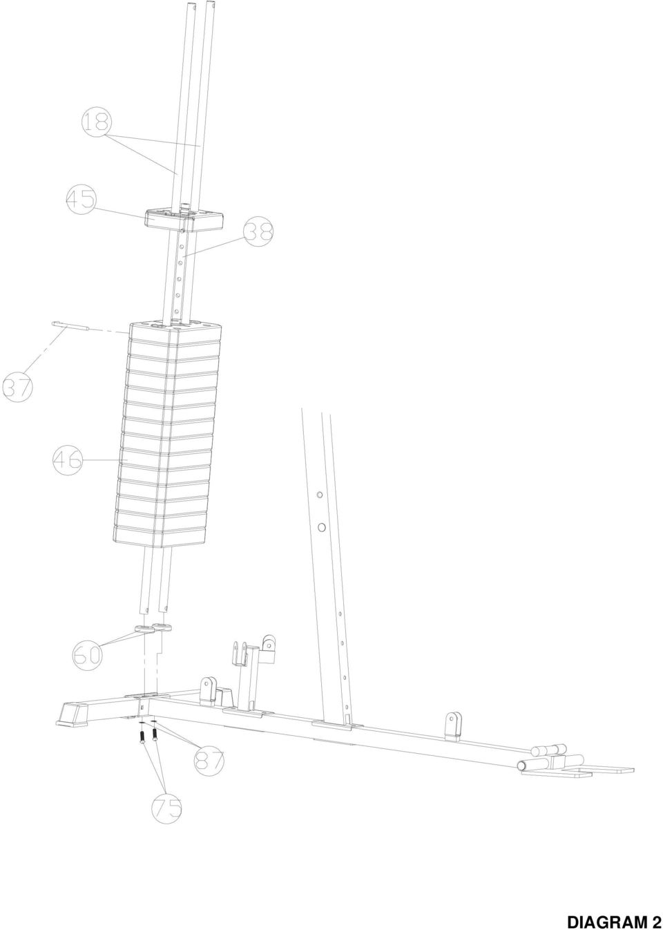
7 STEP 2 (See Diagram 2) A.) Place two 60x25mm Rubber Bumpers (#60) on the Rear Base Frame (#3). Align the holes and insert Two Guide Rods (#18) through the holes into the Rear Base Frame. Secure each Guide Rod with one M10 x 25mm Allen Bolt (#75) and 10mm Washer (#87) from the bottom of Rear Base Frame. B.) Slide 14 Weight Plates (#46) onto the Guide Rods. Make sure all Plates are facing the same direction. Insert the Selector Rod (#38) through the center hole on the Weight Plates. Slide the Weight Selector Stem (#45) onto the Guide Rods. C.) Use the L-shape Pin (#37) to select desired number of Weight Plates to Exercise. NOTE: Each Plate weights 10 lbs. Please refer to the Weight Resistance Chart on page 24.
 through the center hole on the Weight Plates.")
8 DIAGRAM 2
9 STEP 3 (See Diagram 3) A.) Attach the Upper Frame (#4) onto the two Guide Rods (#18). Secure each Guide Rod to the Upper Frame with on M10 x 25mm Allen Bolt (#75) and 10mm Washer (#87). DO NOT tighten the Nuts and Bolts yet. B.) Place the Upper Frame (#4) onto the top of the Vertical Frame (#5). Secure it with one 140x50mm Bracket (#89), two M10 x 70mm Carriage Bolts (#73), two 10mm Washers (#87), and two M10 Nylon Nuts (#88). C.) Securely tighten all Nuts and Bolts previously installed. D.) Attach the Backrest Pad (#22) to the Backrest Support Frame (#12). Secure it with two M8 x 40mm Allen Bolts (#77) and 8mm Washers (#86). E.) Attach the Backrest Support Frame (#12) to the Vertical Frame (#5). Secure it with one M10 x 90mm Allen Bolt (#76), two 10mm Washers (#87), and one M10 Nylon Nut (#88). F.) Thread the Long T-shape Lock Pin (#40) into the hole on the Vertical Frame (#5). Insert the Pin into selected hole on the Backrest Support Frame to obtain the desired Backrest position. G.) Attach the Seat Support Frame (#6) to the Vertical Frame (#5). Secure it with two M10 x 90mm Carriage Bolts (#74), 10mm Washers (#87), and M10 Nylon Nuts (#88). DIAGRAM 3
 Attach the Backrest Pad (#22) to the Backrest Support Frame (#12). Secure it with two M8 x 40mm Allen Bolts (#77) and 8mm Washers (#86). E.")
10 STEP 4 (See Diagram 4) A.) Attach the Leg Developer (#7) to the Seat Support Frame (#6). Align the holes and insert the Axle (#42) into the Leg Developer (#7). Secure it with two M10 x 16mm Allen Bolt (#78), two 10mm Washers (#87). Do not over tighten the Bolts, ensure the Leg Developer is able to swivel. B.) Attach the Front Press Base (#10) to the Upper Frame (#4). Align the holes and insert the Front Press Base Axle (#25). Secure it with two M10 Nylon Nuts (#88) and 10mm Washers (#87). DIAGRAM 4
 Attach the Front Press Base (#10) to the Upper Frame (#4).")
11 STEP 5 (See Diagram 5) A.) Attach the Front Press (#11) to the pivot on the Front Press Base (#10). Align the holes and insert the Front Press Axle (#27) through the holes. B.) Secure each end of the Axle with one M10 x 20mm Allen Bolt (#79) and 10x33 Washer (#61). C.) Thread a Short T-shape Lock Pin (#50) into the hole on the Front Press. Use the Lock Pin to secure the desired Front Press exercise position. DIAGRAM 5
 Thread a Short T-shape Lock Pin (#50) into the hole on the Front Press.")
12 STEP 6 (See Diagram 6) A.) Attach the Butterfly Base (#14) to the Vertical Frame (#5). Secure it with one 120 x 50mm Bracket (#26), two M10 x 90mm Carriage Bolts (#74), two 10mm Washers (#87), and two M10 Nylon Nuts (#88). B.) Insert the Right Butterfly (#20) into the right pivot on Butterfly Base. Secure it with one M10 x 20mm Allen Bolt (#79) and 10mm Washer (#87) from the bottom. C.) Insert the Butterfly Handle (#13) into the pivot on the Right Butterfly. Secure it with one M10 x 20mm Allen Bolt (#79) and 10x33mm Washer (#61). D.) Repeat Procedures B and C above to install the other side. DIAGRAM 6
 Insert the Butterfly Handle (#13) into the pivot on the Right Butterfly. Secure it with one M10 x 20mm Allen Bolt (#79) and 10x33mm Washer (#61). D.")
13 STEP 7 (See Diagram 7) A.) Place the Seat Pad (#21) onto the Seat Post (#9). Secure it with two M8 x 40mm Allen Bolts (#77) and 8mm Washers (#86). B.) Insert the Seat Post (#9) into the opening on the Seat Support Frame (#6). Use a Lock Knob (#41) to obtain the desired height of Seat. C.) Insert two Foam Roll Tubes (#28) halfway through the holes on Seat Post and Leg Developer. Push four Foam Rolls (#59) onto the Tubes from both ends. Plug four Foam Roll End Caps (#54) onto the ends of the Tubes. DIAGRAM 7
 Insert two Foam Roll Tubes (#28) halfway through the holes on Seat Post and Leg Developer.")
14 CABLE LOOP DIAGRAM

15 STEP 8 (See Diagram 8 & Upper Cable Loop Diagram)

16 A.) Attach the 3980 Upper Cable (#31) to the opening on the front Upper Frame (#4). Make sure the ball stopper is underneath the Frame. Attach a Pulley (#43) to the Cable. Secure the Pulley with one M10 x 65mm Allen Bolt (#80), two Pulley Bushings (#56), and one M10 Nylon Nut (#88). B.) Draw the Cable over the Pulley along the Upper Frame towards the back of the machine to the opening in the middle of Upper Frame. Repeat Procedure B above to install a Pulley. C.) Draw the Cable around the Pulley then back to the upper open bracket on the back of Front Press Base (#10). Attach a Pulley to the bracket. Secure it with one M10 x 45mm Allen Bolt (#81), two 10mm Washers (#87), and one M10 Nylon Nut (#88). D.) Draw the Cable around the Pulley then towards the upper opening on the Vertical Frame (#5). Repeat Procedure B above to install a Pulley. E.) Draw the Cable around the Pulley and back to the lower open bracket on the back of Front Press Base (#10). Repeat Procedure C above to install a Pulley. F.) Draw the Cable around the Pulley then to the lower opening on the Upper Frame. Repeat Procedure B above to install a Pulley. G.) Draw the Cable underneath the Pulley then pull upward to the open bracket underneath the Upper Frame. Repeat Procedure C above to install a Pulley. H.) Draw the Cable around the Pulley then downward. Attach a Pulley to the two Double Floating Pulley Brackets (#24). Repeat Procedure C above to install a Pulley. Let the Bracket hanging for now. I.) Draw the Cable around the Pulley then upward to the opening on the back of Upper Frame. Repeat the Procedure C above to install a Pulley. J.) Draw the Cable around the Pulley then downward to the Selector Rod (#41). Thread the Head Bolt at end of the Cable into the Selector Rod. DIAGRAM 8
, two 10mm Washers (#87), and one M10 Nylon Nut (#88). D.) Draw the Cable around the Pulley then towards the upper opening on the Vertical Frame (#5).")
17 Upper Cable Loop Diagram

18
19 STEP 9 (See Diagram 9 & Lower Cable Loop Diagram) A.) Attach the 3900mm Lower Cable (#33) to the opening on the Leg Developer (#7). Attach a Pulley to the opening. Secure it with one M10 x 45mm Allen Bolt (#81),two 10mm Washers (#87) and one M10 Nylon Nut (#88). B.) Draw the Cable underneath the Pulley to the open bracket on the Base Frame (#1). Attach a Pulley to the bracket. Secure it with one M10 x 45mm Allen Bolt (#81), two 10mm Washers (#87), and one M10 Nylon Nut (#88). C.) Draw the Cable underneath the Pulley towards back of the machine through the bottom openings on the Vertical Frame (#5) and Butterfly Pulley Bracket (#17) to the open bracket on the Base Frame (#1). Repeat Procedure B above to install a Pulley with a L-shape Cable Bracket (#67). D.) Draw the Cable underneath the Pulley then pull upward to the Double Floating Pulley Bracket (#24) previously installed in STEP-8. Repeat the Procedure B above to install a Pulley. After completing the entire cable system, come back to the Double Floating Pulley Bracket and adjust the height of the lower Pulley to adjust the tightness of the Cables. E.) Draw the Cable around the Pulley then downward. Attach the Cable to an Angled Double Floating Pulley Bracket (#23). Repeat Procedure B above to install a Pulley. Let the Bracket hanging for now. F.) Draw the Cable around the Pulley then upward to the opening on the Vertical Frame (#5). Attach a Pulley to the opening. Secure it with one M10 x 65mm Allen Bolt (#80), two Pulley Bushings (#56), and one M10 Nylon Nut (#88). G.) Insert the Cable through a Nylon Ball Stopper (#91). Attach the Cable to a U-shape Cable Connector (#66). Secure it with one M10 x 35 Allen Screw (#84), two 10mm Washers (#87), and one M10 Nylon Nut (#88). DIAGRAM 9
 Draw the Cable underneath the Pulley towards back of the machine through the bottom openings on the Vertical Frame (#5) and Butterfly Pulley Bracket (#17) to the open bracket on the Base Frame (#1).")
20

21 Lower Cable Loop Diagram STEP 10 (See Diagram 10 & Butterfly Cable Loop Diagram)
22 A.) Attach one end of the Butterfly Cable (#32) to the open slot on Right Butterfly (#20). B.) Draw the Cable to the open slot on the Butterfly Pulley Bracket (#17). Attach a Pulley to the open slot. Secure the Pulley with one M10 x Allen Bolt (#8), one L-shape Cable Bracket (#), two Washers (#87), and one M10 Aircraft Nut (#8). C.) Draw the Cable underneath the Pulley then upward to the Angled Double Floating Pulley Bracket (#23) previously installed in STEP-9. Install a Pulley. D.) Draw the Cable around the Pulley then downward to the left open slot on the Butterfly Pulley Bracket. Repeat the Procedure B above to install a Pulley. E.) Pull the Cable ant attach it to the open slot on the Left Butterfly (#19). DIAGRAM 10
23 Butterfly Cable Loop Diagram
24 STEP 11 (See Diagram11) A.) Connect the Lat Bar (#8) to the Upper Cable with two C-clips (#36) and one short Chain (#35). B.) Connect the Abdominal Strap (#93) to the mid Cable with a C-clip (#36) And One U-Shape Cable Connector (#66). C.) Connect the Shiver Bar (#30) to the Lower Cable with two C-clips (#36) and one Long Chain (#34). Single Handle (#92) and Ankle Strap (#94) can be attached to C-clip instead of one of the bars when required. DIAGRAM 11
25 WEIGHT RESISTANCE CHART WEIGHT PLATE Station Low Pulley Lat Pull Butterfly Front Press AB Crunch Leg Developer WEIGHT PLATE Station Low Pulley Lat Pull Butterfly Front Press AB Crunch Leg Developer *Numbers are approximate. Actual weight may vary. *Value for butterfly is for each arm.
26 PART LIST KEY NO. DESCRIPTION QTY KEY NO. DESCRIPTION QTY 1. Base Frame 1 2. Foot Plate Axle Ф25x160 Handle Grip 4 3. Rear Base Frame Short T-Shape Lock Pin 1 4. Upper Frame Ф38xФ27 Sleeve 2 5. Vertical Frame x25 End Cap 6 6. Seat Support Frame Square Cap 7 7. Leg Developer Foam Roll End Cap 4 8. Lat Bar Ф25 Flat End Cap 2 9. Seat Post Pulley Bushing Front Press Base Ф38xФ34 Bush Front Press Ф Backrest Support Frame Foam Roll Butterfly Handle Rubber Bumper Ф60x Butterfly base Ф10xФ33 Washer Foot Plate Ф50xФ21 Nylon Bushing Anti Slip Stick Ф25 Damping Butterfly Pulley Bracket Leg Developer Bumper Guide Rod Front Press Bumper Left Butterfly Base U-Shape Cable Connector Right Butterfly Base L-Shape Bracket Seat Pad Bar Protector Backrest Pad Square End Cap Cross Pulley Bracket Ф50 Roll Cap Double Floating Pulley Bracket x50 End Cap Front Press Base Axle Ф25 Bushing *50MM Bracket M10x70 Carriage Bolt Front Press Axle M10x90 Carriage Bolt Foam Roll Tube M10x25 Allen Bolt Shiver Bar Frame M10x90 Allen Bolt Shiver Bar M8x40 Allen Bolt Upper Cable3980mm M10x16 Allen Bolt Butterfly Cable2210mm M10x20 Allen Bolt Lower Cable3900mm M10x65 Allen Bolt Long Chain M10x45 Allen Bolt Short Chain C-Clip M6x16 Philips Screw L-Shape Pin M10x35 Allen Screw Select Rod M10x20 Allen Bolt Ф25mm Roll End Cap Ф8 Washer Long T-Shape Lock Pin Ф10 Washer Lock Knob M10 Nylon Nut Axle x50mm Bracket Pulley Ф25x330Handle Grip Square End Cap Nylon Ball Stopper Selector Stem Single Handle Weight Stack Abdominal Strap mm Frame End Cap Ankle Strap Ф25x145mm Handle Grip Ф38xФ34 Bushing 2
27 HYPER-EXTENSION LIMITED WARRANTY The importer of this machine assures that this device was manufactured from high quality materials. A prerequisite for this warranty is the proper setup in accordance with the operating instructions provided. Improper use and / or incorrect transportation can render the warranty void. The limited warranty on this product is two years from the date of purchase. The warranty does not cover: Damage effected by outer force Intervention by unauthorised parties Incorrect handling of the product Non-compliance of the operating instructions Wear parts and expendable items are also not covered. The device is only intended for private use. The warranty does not apply to professional usage. Spare parts can be ordered by contacting Customer Services on Please make sure you have the following information on hand when ordering spare parts. Operating Instructions Model Number (located on the cover sheet of these instructions) Description of attachments Attachment Number Proof of purchase with purchase date Please don t send the device to our firm without being requested to do so by our Service team. The costs of unsolicited shipments will be borne by the sender.
HOME GYM ADI-10250-I. Model ADI-10250-I. Retain This Manual for Reference OWNER'S MANUAL
 NOTE: Please read all instructions carefully before using this product Table of Contents Safety Notice HOME GYM ADI-10250-I Important Assembly Information Care and Maintenance Parts List Warranty Ordering
4 in 1 Strength Station
 Revision 0 September 2010 4 in 1 Strength Station Owner s Manual Record Serial Number Here Platinum by Tunturi www.tunturi.com Date www.tunturi.com of Purchase 4 in 1 Strength Station Owner s Manual Instructions
HYDRAULIC LIFT TABLE CART 2200-LB.
 HYDRAULIC LIFT TABLE CART 2200-LB. OWNER S MANUAL WARNING: Read carefully and understand all MACHINE ADJUSTMENT AND OPERATION INSTRUCTIONS before operating. Failure to follow the safety rules and other
UNIVERSAL PARTS - PRICE LIST
 Power Circuit PART # UNIVERSAL PARTS - PRICE LIST prices subject to change 8/15/2003 887422 DESCRIPTION UNIT QTY TOTAL 6000 Shoulder Press PRICE ORDERED 600875-SK Cable Kit $ 18.25 6001 Lat Pulldown 600876-SK
HYDRAULIC TABLE CART 500-LB.
 HYDRAULIC TABLE CART 500-LB. OWNER S MANUAL WARNING: Read carefully and understand all MACHINE ADJUSTMENT AND OPERATION INSTRUCTIONS before operating. Failure to follow the safety rules and other basic
OWNER S MANUAL Table Tennis Table Patent Pending
 OWNER S MANUAL Table Tennis Table Patent Pending Be sure to write your model number and serial number here for future reference. You can find these numbers printed on the bottom of the table. MODEL # T8179
READ CAREFULLY - FAILURE TO FOLLOW INSTRUCTIONS AND SAFETY RULES MAY RESULT IN SERIOUS INJURY
 Owner s Manual LSP16H LS3001 LS3002H LS3003 LSP21H LS3101 LS3102H LS3103 LSP24H LS3201 LS3102H LS3103 LSP28H LS3301 LS3302H LS3303 mainframe bundle H-unit bundle accessory box mainframe bundle H-unit bundle
Micro Cart User's Guide
 Micro Cart User's Guide To take full advantage of the ergonomic features of your new Sun Mountain Micro Cart, please read the following information. SUN MOUNTAIN 1 Your Micro Cart has several innovative
NBA Arena Portable System
 REQUIRED TOOLS AND MATERIALS: Two (2) Capable Adults Tape Measure Wood Board 6 x 6 (scrap) N53 W24700 South Corporate Circle Sussex, WI 53089 U.S.A. NBA Arena Portable System Sawhorse or Support Table
XM-4434. Owner s Manual POWER TOWER !CAUTION. Read all precautions and instructions in this manual before using this equipment.
 XM-4434 POWER TOWER Owner s Manual!CAUTION Read all precautions and instructions in this manual before using this equipment. Table of Contents Important Safety Information 3 Assembly 4-7 Parts List 8 Exploded
SERVICE MANUAL. Corpus 3G. Seat system for electric wheelchair
 SERVICE MANUAL US Corpus 3G Seat system for electric wheelchair How to contact Permobil Head Office of the Permobil group Produced and published by Permobil AB, Sweden Version 4, 2014-07 Item No.: 205260-US-0
1000-LB. TRAILER JACK OWNER S MANUAL
 1000-LB. TRAILER JACK OWNER S MANUAL WARNING: Read carefully and understand all INSTRUCTIONS before operating. Failure to follow the safety rules and other basic safety precautions may result in serious
Assembly and Usage Instructions
 Assembly and Usage Instructions A Product 5885 West Van Horn Tavern Road Columbia, MO 65203 www.caldwellshooting.com Instruction #1001667 Limited Warranty Every Caldwell product is warrantied to be free
R O A D M A S T E R, I N C.
 R O A D M A S T E R, I N C. 11 10 20 12 4 18 19 1 2 13 16 ITEM QTY NAME MATERIAL 1...2... 1/2" x 3 1/2" BOLT... 350103-00 2...2... 1/2" x 2" BOLT... 350097-00 3...6... 1/2" x 1 1/2" BOLT... 350095-00 4...2...
In-Ground Basketball System Owners Manual
 In-Ground Basketball System Owners Manual Customer Service Center N53 W4700 South Corporate Circle Sussex, WI 53089 U.S.A. Write Model Number From Box Here: WARNING! 3 Capable Adults REQUIRED TOOLS AND
FRONT BUMPER INSTALLATION INSTRUCTIONS 2007-2011 DODGE / MERCEDES SPRINTER
 Aluminess Products Inc 9402 Wheatlands Ct. #A Santee, CA 92071 619-449-9930 FRONT BUMPER INSTALLATION INSTRUCTIONS 2007-2011 DODGE / MERCEDES SPRINTER Please read before beginning Stainless steel hardware
Wanda Technology Inc. Side Post Aluminum Umbrella OWNER S MANUAL
 Wanda Technology Inc. Side Post Aluminum Umbrella Portofino II Series OWNER S MANUAL US Patents: 6,439,249 ; 6,692,135 ; 6,598,990 ; 6,966,667 6,945,263 ; 6,923,194 ; 6,830,058 ; 6,565,060 6,511,033 ;
CAR SEAT/ STROLLER INSTRUCTION MANUAL
 CAR SEAT/ STROLLER INSTRUCTION MANUAL English PM-0624AB 3/98 Do not use this 4-in-1 System until you read and understand these instructions! IMPORTANT INFORMATION Thank you for selecting this 4-in-1 System
SLACK PERFORMANCE KARTS
 SLACK PERFORMANCE KARTS SET UP GUIDE Thank you for purchasing a 2013 Slack Axiom Chassis. Performance Mfg. strives to provide you with the very best chassis and components on the market today. Your satisfaction
SP-880 OWNER S MANUAL
 OWNER S MANUAL Product may vary slightly from the item pictured due to model upgrades Read all instructions carefully before using this product. Retain this owner s manual for future reference. NOTE: This
USER S MANUAL QUESTIONS? CAUTION. Model No. WEEVBE1926.0 Serial No. Write the serial number in the space above for future reference.
 Model No. WEEVBE1926.0 Serial No. Write the serial number in the space above for future reference. USER S MANUAL Serial Number Decal (Under Seat) QUESTIONS? As a manufacturer, we are committed to providing
Table of Contents WARNING SYMBOLS AND DEFINITIONS
 Table of Contents SAFETY INSTALLATION OPERATION MAINTENANCE Safety... 2 Specifications... 4 Installation... 5 Operation... 8 WARNING SYMBOLS AND DEFINITIONS Maintenance... 9 Parts List and Assembly Diagram...
Rating when used as a weight carrying hitch without spring bars:
 BOLT-TOGETHER WEIGHT DISTRIBUTING HITCH SYSTEM Rating when used as a weight distributing hitch with spring bars: Part Number 48051 4805 48053 48054 Max Tongue Weight 550 Ibs. 750 Ibs. 1000 Ibs. 1400 lbs.
FL ADJUSTABLE RIDER BACKREST MOUNTING HARDWARE KIT
 -J070 REV. 0-0-0 FL ADJUSTABLE RIDER BACKREST MOUNTING HARDWARE KIT GENERAL Kit Number 9-09A Models For model fitment information, see the P&A Retail Catalog or the Parts and Accessories section of www.harley-davidson.com
For maximum effectiveness and safety, please read this Owner's Manual before using your Torso Track 2.
 For maximum effectiveness and safety, please read this Owner's Manual before using your Torso Track 2. TABLE OF CONTENTS Introduction...2 Important Safety Tips...3 Product Specifications...4 Set Up...5-6
Auto-belay Cable Replacement Process
 Auto-belay Cable Replacement Process Version 2.00 WARNING: The air pressure in the auto-belay system is what causes the cable to be retracted when releasing the cable or climbing the wall with the cable
Zuma Strength-Training Fitness Equipment. Assembly and Maintenance Guide
 Zuma Strength-Training Fitness Equipment Assembly and Maintenance Guide Important Safety Instructions for Using the Equipment Before beginning any fitness program, you should obtain a complete physical
USER'S MANUAL QUESTIONS? CAUTION. Visit our website at. www.nordictrack.com. new products, prizes, fitness tips, and much more!
 Patent Pending Model No. NTEX04900 Serial No. USER'S MANUAL Serial Number Decal QUESTIONS? As a manufacturer, we are committed to providing complete customer satisfaction. If you have questions, or if
6 inch A-Arm Lift Kit WARNING: 16-018/16-019. installation instructions. will fit CLUB CAR DS. included:
 Revised May 205 6-08/6-09 6 inch A-Arm Lift Kit will fit CLUB CAR DS installation instructions included: Rear Lift Blocks Main Suspension Assembly Spindles A-Arms Rear Shock Mounting Plates U-Bolts WARNING:
PALLET JACK - 2.5 TON
 PALLET JACK - 2.5 TON 39939 SET UP AND OPERATING INSTRUCTIONS Visit our website at: http://www.harborfreight.com Read this material before using this product. Failure to do so can result in serious injury.
Instructions and precautions. Fork Height. Visit our website at: http://www.harborfreight.com
 Pallet Jack Item 68760 / 68761 Instructions and precautions Specifications Capacity Control Lever Fork Height Fork Length Fork Width Maximum Minimum Width over Forks Steering Wheel Dia. 2-1/2 Ton (5,000
Seismic Installation for Attic Storage System
 Your Performance Partner Seismic Installation for Storage System CONTENTS SSafety Precautions................................. 2 Required Tools..................................... 2 Parts and Fastener
Caboose Too Rear Seat Instruction Manual 0090X & 0091X Series
 Caboose Too Rear Seat Instruction Manual 0090X & 0091X Series Joovy 2919 Canton Street Dallas, TX 75226 (877) 456-5049 Fax: (214) 761-1774 Email: [email protected] Web Site: www.joovy.com ! WARNING
Triple Threat 3-in-1 Game Table 3 IN 1 GAME TABLE
 NG0M Triple Threat 3-in- Game Table 3 IN GAME TABLE Thank 3 in Y Game Table Thank you for your purchase of our product. We work around the clock and around the globe to ensure that our products maintain
Weatherproof Tournament Table Tennis Table
 Weatherproof Tournament Table Tennis Table Owner s Manual Model Number 7035-590 Absolutely Weatherproof Printed on 100% recycled paper.! Made in Germany Thank you for purchasing our high quality KETTLER
R O A D M A S T E R, I N C.
 R O A D M A S T E R, I N C. MOUNTING BRACKET KIT 12 3 6 9 5 11 ITEM QTY NAME MATERIAL 1...4...1/2" x 1 1/2" BOLT... 350095-00 2...4...1/2" x 1 1/2" CARRIAGE BOLT... 350362-00 3...8...1/2" NUT... 350258-00
Range Road RR Series Semi-Automatic Firewood Processor. Crated Unit Assembly Manual
 Range Road RR Series Semi-Automatic Firewood Processor Crated Unit Assembly Manual 1 1) Undo 8-18mm x 19mm Nuts and bolts, 2 on each leg of top frame 2) Lift top of Metal crate off and move out of work
R O A D M A S T E R, I N C.
 R O A D M A S T E R, I N C. ROADMASTER, Inc. 6110 NE 127th Ave. Vancouver, WA 98682 6 13 11 MOUNTING BRACKET KIT Cable Tab 14 12 7 15 9 Cable Tab 360-896-0407 fax 360-735-9300 www.roadmasterinc.com ITEM
BCG. Assembly Instructions MINI STEPPER F1BC6059
 BCG Assembly Instructions MINI STEPPER FBC6059 Please keep this instruction manual for future reference -Adult Assembly required: Keep all parts out of the reach of children Customer Service: (888) 9-336,
R O A D M A S T E R, I N C.
 R O A D M A S T E R, I N C. ROADMASTER, Inc. 6110 NE 127th Ave. Vancouver, WA 98682 12 10 3 11 4 5 13 7 8 360-896-0407 fax 360-735-9300 www.roadmasterinc.com ITEM QTY NAME MATERIAL 1... 4...1/2 x 1 1/2
SET-UP AND INSTALLATION FOR LEAD SCREW CARTRIDGE ASSEMBLY
 SET-UP AND INSTALLATION FOR LEAD SCREW CARTRIDGE ASSEMBLY 82-13-1 O-Ring (Rear) The Lead Screw Assembly is shipped separately. Note: Install Electrical and Pneumatic Circuitry. Be Sure electrical and pneumatic
Owner s Manual Read and keep this manual. Patents World Wide
 Owner s Manual Read and keep this manual. Patents World Wide S & S Industries, Inc., Sarasota, FL, USA www.trail-gator.com Copyright 2008 All Rights Reserved The following manual is provided to assist
LG G5 Chassis Brace Gen 5 Camaro THE MOST POWERFUL HEADERS ON THE PLANET Brought to you by LG Motorsports 972-429-1963
 LG G5 Chassis Brace Gen 5 Camaro THE MOST POWERFUL HEADERS ON THE PLANET Brought to you by LG Motorsports 972-429-1963 Thank you for purchasing LG Motorsports products for your Gen 5 Camaro. Parts Inventory:
Multi-Pitch Pitching Machine USER MANUAL
 Multi-Pitch Pitching Machine USER MANUAL TABLE OF CONTENTS Thank you for purchasing the Cimarron Multi-Pitch Pitching Machine. The Cimarron Multi-Pitch Pitching Machine is a high performance pitching machine
ELLIPTICAL EXERCISER. User s Manual CAUTION. Assembly Operation Maintenance Part List and Drawing. Sears, Roebuck and Co., Hoffman Estates, IL 60179
 Model No. 831.285420 Serial No. ELLIPTICAL EXERCISER User s Manual Serial Number Decal Assembly Operation Maintenance Part List and Drawing CAUTION Read all precautions and instructions in this manual
POWER LOCK KIT GENERAL INSTALLATION -J04427 REV. 2007-12-04. Kit Number. Models. Additional Parts Required. Kit Contents
 -J0 REV. 00--0 POWER LOCK KIT GENERAL Kit Number -0, 0-0 Models For model fitment information, please see the P&A Retail Catalog or the Parts and Accessories section of www.harleydavidson.com (English
Lunette 2 Series. Curved Fixed Frame Projection Screen. User s Guide
 Lunette 2 Series Curved Fixed Frame Projection Screen User s Guide Important Safety and Warning Precautions Please follow these instructions carefully to ensure proper maintenance and safety with your
INSTALLATION AND OPERATING INSTRUCTIONS For Model GL1 Gate Locks
 Securitron Magnalock Corp. www.securitron.com ASSA ABLOY, the global leader Tel 800.624.5625 [email protected] in door opening solutions INSTALLATION AND OPERATING INSTRUCTIONS For Model GL1 Gate
DLC:GH B6CJ6A HJEEA:B:CI
 SERIES 2 S E RI E S 2 DLC:GH B6CJ6A HJEEA:B:CI SERIAL NUMBER Z2SUPP_0211Rev B - READ THIS MANUAL DO NOT OPERATE THIS WHEELCHAIR WITHOUT FIRST READING AND UNDERSTANDING THIS TiLITE OWNERS MANUAL SUPPLEMENT.
BUGGY SETUP GUIDE. Volume GOKARTSUSA GY6 150, CN250. Buggy Setup Guide
 BUGGY SETUP GUIDE Volume 1 GOKARTSUSA GY6 150, CN250 Buggy Setup Guide GY6 150, CN250 DUNE BUGGY Buggy Setup Guide GOKARTSUSA.COM 2000 Highway 50 S. Lake Tahoe, CA 96150 Phone 800.603.1437 2 Table of Contents
R O A D M A S T E R, I N C.
 R O A D M A S T E R, I N C. MOUNTING BRACKET KIT 14 8 7 4 13 5 6 ITEM QTY NAME MATERIAL 1...6...1/2" x 2 1/2" BOLT... 350099-00 2...2...1/2" x 1 1/2" BOLT... 350095-00 3...8...1/2" LOCK WASHER... 350309-00
INSTRUCTIONS AND PARTS LIST FOR MODEL 70H & 75H HAND-OPERATED HYDRAULIC PRESS
 INSTRUCTIONS AND PARTS LIST FOR MODEL 70H & 75H HAND-OPERATED HYDRAULIC PRESS SETTING UP THE PRESS FOR OPERATION For shipping convenience, the gauge, pump handle, hoist crank, screw nose and base angles
DeskCycleTM USER S MANUAL QUESTIONS / PROBLEMS. Order# Support for US Customers TOLL-FREE SUPPORT 877-426-3292 EMAIL SUPPORT support@3dinnovations.
 TM DeskCycleTM USER S MANUAL Visit us at www.deskcycle.com for, Usage Tips Calorie Calculator Accessories And More QUESTIONS / PROBLEMS Support for US Customers TOLL-FREE SUPPORT 877-426-3292 EMAIL SUPPORT
149mm. Walk-Thru Assembly Gate. MODEL NO: 1161, 1167 Owner s Manual. www.regalo-baby.com
 149mm 210mm Walk-Thru Assembly Gate MODEL NO: 1161, 1167 Owner s Manual READ ALL INSTRUCTIONS BEFORE ASSEMBLY AND USE OF GATE. KEEP INSTRUCTIONS FOR FUTURE USE. www.regalo-baby.com... Regalo International,
TONNEAU INSTALLATION GUIDE
 TONNEAU INSTALLATION GUIDE Warranty, Care & Maintenance Model 4056 Toyota Tacoma Double Cab 5' Short Bed 2005-Current (With Multi-Track System) EASY AS 1-2-3! NORMAL INSTALLATION TIME 30 MINUTES For Warranty
Dive Rite 200 & 300 Bar Isolator Manifold Service Manual
 Dive Rite 200 & 300 Bar Isolator Manifold Service Manual Principal Photography and Text by Pete Nawrocky Copyright 2003 Lamartek Inc. D/B/A Dive Rite 0 Warning This manual is only to be used as a guide
CETAC Z-Drive Assembly
 CETAC Z-Drive Assembly Replacement Guide Manual Part Number 610144 Rev 1, 2012 CETAC Technologies, Printed in USA Overview This guide describes the necessary steps to replace the Z-drive assembly on your
Original Assembly Guide
 TCT Multipurpose Single Bevel Sliding Compound Mitre Saw Original Assembly Guide Read instructions before assembling this tool. Table of Contents GB Assembly Guide Read instructions before assembling this
Number Wheeler P/N Description Set Rex P/N Notes 1 603500 Base 1 J001 2 603501 Support, Right 1 J002 3 603502 Support, Left 1 J003 4 600328 Nut (M8)
") 1 603500 Base 1 J001 2 603501 Support, Right 1 J002 3 603502 Support, Left 1 J003 4 600328 Nut (M8) 4 5 600130 Spring Washer (8mm) 4 6 600344 Roll Pin (M6x30) 4 7 600129 Socket Hd Cap Screw (M8x25) 4 8
1 603500 Base 1 J001 2 603501 Support, Right 1 J002 3 603502 Support, Left 1 J003 4 600328 Nut (M8) 4 5 600130 Spring Washer (8mm) 4 6 600344 Roll Pin (M6x30) 4 7 600129 Socket Hd Cap Screw (M8x25) 4 8
BODY-12, Door Handle - Removal, Installation, and Adjustment
 Introduction BODY-12, Door Handle - Removal, Installation, and Adjustment There are many different procedures floating around describing how to replace the door handles on a 944 and every one of them will
Deluxe Welding Tool Chest
 Item# 164782 OPERATOR S MANUAL Read carefully and understand RULES FOR SAFE OPERATION and instructions before operating. Failure to follow the safety rules and other basic safety precautions may result
1 TON FOLDING CRANE CFC1000
 1 TON FOLDING CRANE CFC1000 OPERATION &MAINTENANCE INSTRUCTIONS 0401 SPECIFICATIONS MAXIMUM SAFE WORKING LOADS (kg) 1 2 3 4 1000 750 500 250 MAXIMUM LIFT HEIGHT - 1920mm HYDRAULIC RAM OIL CAPACITY - 450CC
1-800-295-5510 uline.com SPECIFICATIONS
 H-1394, H-1395, H-1396 H-1397, H-3859, H-3860 π GRAVITY CONVEYOR 1-800-295-5510 uline.com SPECIFICATIONS Conveyor Bed Width In (mm) 18, 24, 30 (457, 610, 762) Load Capacity Per Linear Foot (305mm) Lbs
HC-3000 SERIES RAKE Parts Breakdown DURABILT INDUSTRIES, LLC - 1810 AIRPORT ROAD POCAHONTAS ARKANSAS 72455
 HC-3000 SERIES RAKE Parts Breakdown 1 SPRING TOWER PARTS PAGE 4 RAKE WHEEL AND ARM PARTS PAGE 8 PIVOT PARTS PAGE 6 6 2,3,4 23 21 7 22 24 HUB & SPINDLE PARTS 8 THRU 20 HYDRAULIC PARTS PAGES 10 AND 12 1
Front axle components, overview
 just a test. Front axle components, overview 40-1 General Information Load bearing components and parts of the suspension must not be welded or straightened. Vehicles without drive axle must not be moved,
Infant Car Seat Adapter Instructions
 Infant Car Seat Adapter Instructions Congratulations on your purchase of the BOB Infant Car Seat Adapter (ICSA). It is designed to allow the attachment of an Infant Car Seat to your BOB Stroller. Please
Pulleys and Belt. Install the Major Accessory and Pulley. Install the Motor Pulley NOTE. Align the Motor Pulley and the Tool Pulley NOTE
 Pulleys and Belt Pulley Guard - 505862 Install the Major Accessory and Pulley 1. Place the short end of the mounting base holes, and insert - but don t tighten - the setscrews. If the Major Accessory has
R O A D M A S T E R, I N C.
 R O A D M A S T E R, I N C. 11 7 6 1 2 10 13 8 ITEM QTY NAME PART # 1...2...1/2 x 5 1/2 BOLT...350108-00 2...4...1/2 x 1 3/4 BOLT...350096-00 3...6...1/2 LOCK WASHER...350309-00 4...6...1/2 HEX NUT...350258-00
Double Glider Assembly Instructions.
 Double Glider Assembly Instructions. Thank you for purchasing your new Torrans Manufacturing Company s Lawn Glider. Assembly of the Glider can be accomplished by one person however, it is advised that
R O A D M A S T E R, I N C.
 R O A D M A S T E R, I N C. ROADMASTER, Inc. 6110 NE 127th Ave. Vancouver, WA 98682 4 MOUNTING BRACKET KIT 1 2 3 360-896-0407 fax 360-735-9300 www.roadmasterinc.com ITEM QTY NAME PART # 1...2... #10 x
MEASURING WHEEL ALIGNMENT
 MEASURING WHEEL ALIGNMENT 2003-04 WHEEL ALIGNMENT Specifications & Procedures - Hummer - H2 Steering and vibration complaints are not always the result of improper alignment. One possible cause is wheel
Installation Instructions HighRock 4x4 TM
 Installation Instructions HighRock 4x4 TM Slider Step Vehicle Application: Jeep YJ and TJ Wrangler 1986 2006 Part Number: 49312 www.bestop.com - We re here to help! Visit our web site and click on Ask
Service Manual Rol-Lift
 R 2000 Service Manual Rol-Lift Series: T and E Developed by Generic Parts Service This manual is intended for basic service and maintenance of the Rol-Lift pallet jack. The pallet jacks you are servicing
Johnny G Spinner Pro and Johnny G Spinner Elite Owner s Manual
 Johnny G Spinner Pro and Johnny G Spinner Elite Owner s Manual www.startrac.com Table of Contents: 1) Introduction 2) Fitness Safeguards 3) Spinner Pro and Elite Features 4) Assembly Instructions / Parts
758 Heavy-duty Ratchet Guy Wire Cutter
 INSTRUCTION MANUAL 758 Heavy-duty Ratchet Guy Wire Cutter Read and understand all of the instructions and safety information in this manual before operating or servicing this tool. Register this product
Installation instruction do88 Intercooler for Volvo S40 / V50 / C30
 Installation instruction do88 Intercooler for Volvo S40 / V50 / C30 This instruction shows how to replace the OEM intercooler with our performance intercooler. 2. 3. 1. 4. 5. Part number: ICM-170 6. At
Please Do Not Return This Product to the Store!
 MODEL NO. B400W GS60 BASKETBALL SYSTEM O W N E R ' S M A N U A L 1. Read this manual carefully before starting assembly. Read each step completely before beginning each step.. Some smaller parts may be
WARNING TO END USER, INSTALLER AND SELLER OF THIS PART!
 WARNING TO END USER, INSTALLER AND SELLER OF THIS PART! By installing this part you are accepting full responsibility and liability for proper wheel and tire fitment after installation. It is the installer
BILLET HEADLAMP WITH SHORT/TALL MOUNTS
 -J099 REV. 00-0- BILLET HEADLAMP WITH SHORT/TALL MOUNTS GENERAL Kit Number 9-0, 9-0 Models Kit 9-0 is a -/ inch headlamp and kit 9-0 is a -/ inch headlamp. Both kits will fit the models listed in Table.
WARNING! WARNING! ALWAYS WEAR A TMA APPROVED FALL ARREST SYSTEM WHEN USING ANY TREESTAND
 WARNING! You must read and understand all of the following instructions before first use. If you do not, it could result in serious injury up to and including death. Any questions please call 309-691-9653.
MODEL 565E - 22 TON AIR/HYDRAULIC AXLE JACK
 1 565AKHU HYDRAULIC 1.22 O-RING - 2 REQUIRED UNIT 1.23 O-RING COMPLETE 1.24 TEFLON O-RING 2 REQUIRED 1.3 EXTENSION SCREW 1.3A SPRING PIN 1.4 SPRING SUPPORT 1.5 SCREW BUSHING 1.6 Y SHAPE SEAL RING 1.7 HEAD
STEADYfast Stabilizer Installation Notes Fifth Wheel and Travel Trailers 11/23/13
 STEADYfast Stabilizer Installation Notes Fifth Wheel and Travel Trailers 11/23/13 (See Supplemental Instructions for trailers with heavy duty round footplates and/or Power Leveling Systems) PHONE SUPPORT
Front brakes (FN- 3), servicing
, servicing") j a t Front brakes (FN- 3), servicing 46-1 Front brakes, servicing Note: Install complete repair kit. After replacing brake pads and before moving vehicle, depress brake pedal several times firmly to properly
j a t Front brakes (FN- 3), servicing 46-1 Front brakes, servicing Note: Install complete repair kit. After replacing brake pads and before moving vehicle, depress brake pedal several times firmly to properly
Small Flat Panel Lift Arm FSA-1004 and KSA-1004
 I N S T A L L A T I O N I N S T R U C T I O N S Small Flat Panel Lift Arm FSA-1004 and KSA-1004 The Lift Arm is an accessory that can be used with a broad range of Small Flat Panel Displays. The allows
IMPORTANT INFORMATION - PLEASE READ. Table of Contents. Introduction. General Information
 IMPORTANT INFORMATION - PLEASE READ Introduction Congratulations! Welcome to the world of the ELLIPTICAL CROSS TRAINER. The ELLIPTICAL CROSS TRAINER is one of the finest and most comprehensive pieces of
USER MANUAL EN IN 2678 Magnetic Treadmill with Ski Function insportline Excel Run
 USER MANUAL EN IN 2678 Magnetic Treadmill with Ski Function insportline Excel Run 1 CONTENTS IMPORTANT SAFETY INFORMATION... 3 EXPLODED VIEW... 4 PARTS LIST OF EXPLODED VIEW... 5 ASSEMBLING INFORMATION...
SWIM N DUNK CHALLENGE RESIDENTIAL BASKETBALL GAMES And COMMERCIAL ASSEMBLY AND INSTALLATION INSTRUCTIONS
 SWIM N DUNK CHALLENGE RESIDENTIAL BASKETBALL GAMES And COMMERCIAL BASKETBALL GAMES ASSEMBLY AND INSTALLATION INSTRUCTIONS CORPORATE HEADQUARTERS WESTERN SALES AND MANUFACTURING PLANT P.O. Box 400 Canby,
Under Desk Ellip.cal Model # 3015-002
 Under Desk Ellip.cal Model # 3015-002 www.thefitdesk.com 1 BEFORE RETURNING THIS PRODUCT TO PLACE OF PURCHASE CONTACT US FOR ASSEMBLY INSTRUCTIONS, MISSING PARTS, OR FOR HELP WITH A QUESTION at : [email protected]
SERVICE PARTS LIST PAGE 1 OF 6 BASE ASSEMBLY SPECIFY CATALOG NO. AND SERIAL NO. WHEN ORDERING PARTS 12" DUAL BEVEL COMPOUND MITER SAW B27A
 PAGE 1 OF 6 BASE ASSEMBLY 00 0 EXAMPLE: Component Parts (Small #) Are Included When Ordering The Assembly (Large #). SPECIFY CATALOG NO. AND NO. WHEN ORDERING PARTS 1 02-80-0050 Thrust Bearing (1) 2 05-80-0510
Rollator Cane and Brake Replacement SAFETY SUMMARY (CONTINUED)
") Rollator Cane and Replacement Assembly, Installation and Operating Instructions SAVE THESE INSTRUCTIONS NOTE: Check ALL parts for shipping damage. If shipping damage is noted, DO NOT use. Contact Carrier/Dealer
Rollator Cane and Replacement Assembly, Installation and Operating Instructions SAVE THESE INSTRUCTIONS NOTE: Check ALL parts for shipping damage. If shipping damage is noted, DO NOT use. Contact Carrier/Dealer
Your New Frog Bike. Congratulations on purchasing a new bike and thank you for choosing Frog!
 Your New Frog Bike Congratulations on purchasing a new bike and thank you for choosing Frog! We know that you must be raring to go but before you do there s a few little things still to do to get you up
MUSTANG II IFS COMPLETE PARTS PACKAGE
 MUSTANG II IFS COMPLETE PARTS PACKAGE Your Southern Rods & Parts Mustang II IFS Parts Package contains the following items: 1 pr) Upper Control Arms (2023) 1) Upper Arm Bolt Kit (MP-001-A) 1 pr) Lower
AZEK Rail Install Guide
 TRIM MOULDING DECK PORCH RAIL PAVERS AZEK Rail Install Guide Installing AZEK Rail with CableRail by Feeney... 1 Installing CableRail by Feeney for AZEK Rail... 7 Installing AZEK Rail Stairs with CableRail
Pallet Jack. OWNER S MANUAL Model MH1230. Important Safety Instructions Assembly Instructions Parts and Hardware Identification
 OWNER S MANUAL Model MH1230 Important Safety Instructions Assembly Instructions Parts and Hardware Identification Pallet Jack CAUTION: Read, understand and follow ALL instructions before using this product
1.8 CRANKSHAFT OIL SEALS
 SERIES 60 SERVICE MANUAL 1.8 CRANKSHAFT OIL SEALS An oil seal is fitted between each end of the crankshaft and the bores of the flywheel housing and gear case cover to retain the lubricating oil in the
Best/Flex Roller Expandable Conveyor
 Best Diversified Products Ltd. Best/Flex Roller Expandable Conveyor Product Manual Best Diversified Products Ltd. Brunel Road, Earlstrees Industrial Estate Corby, Northants. NN17 4JW Tel: +44(0) 1536 206969
Flat Bottom Long Ram Hydraulic Jack
 Flat Bottom Long Ram Hydraulic Jack 3 Ton 8 Ton 36468 36469 ASSEMBLY & OPERATING INSTRUCTIONS 349 Mission Oaks Blvd., Camarillo, CA 930 Visit our Web site at http://www.harborfreight.com TO PREVENT SERIOUS
MGB Chrome Bumper Conversion
 MGB Chrome Bumper Conversion Installation Instructions For 1974 1/2-1980 MGB This kit requires cutting, welding, and painting. Professional installation recommended. Note: Every MGB body is slightly different
Mounting Tripod Kit Installation Manual
 Mounting Tripod Kit Installation Manual For use with Davis s wireless and cabled Vantage Pro2 weather stations, the Mounting Tripod simplifies installation. The tripod supports the Integrated Sensor Suite
INSTRUCTION MANUAL AND PARTS LIST MODEL 14-10
 VERTICAL BAND SAWS INSTRUCTION MANUAL AND PARTS LIST MODEL 1-10 DAKE/PARMA WHEN ORDERING PARTS GIVE COMPLETE SERIAL NUMBER OF MACHINE GIVE PART NUMBER AND NAME GIVE AMOUNT REQUIRED Unless the above data