CBM2096. USB 2.0 Flash Disk Controller. Datasheet. Rev 1.0
|
|
|
- Cameron Hodge
- 9 years ago
- Views:
Transcription
1 CBM2096 USB 2.0 Flash Disk Controller Datasheet Rev 1.0 Shenzhen Chipsbank Technologies Co.,Ltd. 7/F,Building No.12,Keji Central Road 2, Software Park, High-Tech Industrial Park, Shenzhen, P.R.China Tel: Fax: URL: Contained herein Copyright by Shenzhen Chipsbank Technologies Co.,Ltd. all rights reserved. CBM2096 Datasheet /02/2011

2 Revision History Date Rev No Description Initial release CBM2096 Datasheet /02/2011

3 Contents 1 DESCRIPTION FEATURES BLOCK DIAGRAM PIN ASSIGNMENT TQFP48 (TOP SIDE) PIN DESCRIPTION ELECTRICAL CHARACTERISTICS ABSOLUTE MAXIMUM RATINGS RECOMMENDED OPERATING CONDITIONS STATIC CHARACTERISTICS DYNAMIC CHARACTERISTICS Normal NAND FLASH Dynamic characteristics ONFI NAND FLASH Dynamic characteristics TOGGLE NAND FLASH Dynamic characteristics MECHANICAL DIMENSIONS PIN CBM2096 PACKAGE OUTLINE DIMENSION COPYRIGHT NOTICE CBM2096 Datasheet /02/2011

4 1 Description Fastest & Securest USB 2.0 Flash Disk Controller with dedicated 32-bit microprocessor The CBM2096 is the USB 2.0 Flash Disk controller with the fastest transfer speed on the market. CBM2096 can reach theoretical flash access speed limit of over 32MByte/s for read and 20MByte/s for write. The on-the-fly ECC engine is capable of correcting up to 16/25/29/30bits per 1024 bytes page. For data security, CBM2096 is designed with both hardware and software data protection technology to prevent data corruption even if it is powered off or unplugged during data transfer. The CBM2096 supports all 8 /16 bit BUS wide async NAND flash memory available in the market. New flash can be supported by software re-configuration. The CBM2096 supports all 8 bit BUS wide ONFI/TOGGLE NAND flash memory available in the market. New flash can be supported by software re-configuration. The CBM2096 has both a) 5V to 3.3V LDO and b) power on reset circuits integrated. Thus greatly reduced BOM cost and eased layout burden. The CBM2096 can work properly with no external crystal. It was popularly used for UDP products. The CBM2096 runs smoothly with all available hosts and PC platforms. Complied with USB specification rev. 2.0, the CBM2096 can be supported without additional driver under Win XP, Win 2000, Windows Me, Mac OS and Linux OS. With device driver installed, it can support Win 98/98SE as well. Comprehensive applications, such as PC boot up, disk partitions, password check for security disk, are available as part of our standard mass production software package. The CBM2096 is available in 48-pin TQFP and 64-pin LQFP package, which are thinnest and smallest on the market. The 48-pin CBM2096 and the 64-pin CBM2096 all support up to 8 flash chips. Customers can choose different packages to meet their design requirement. 2 Features USB Interface High-speed USB 2.0 interface; Fastest data transfer rate on the market Single-channel mode(16bit): 32MB/s for Read, 20MB/s for Write Single-channel mode(8bit): 26MB/s for Read, 20MB/s for Write Fastest file copy rate on the market. On-the-fly ECC built-in Hardware enhances reliability ECC for NAND flash: 16/25/29/30 bit per page (1 page = 1024 bytes) Special wear leveling algorithm to improve the flash life-time Hardware & Software Data Protection Technology Prevent data corruption even if it is powered off or unplugged during data transfer. CBM2096 Datasheet /02/2011

5 SLC & MLC & TLC NAND Flash Interface Support 8-bit and 16-bit Samsung SLC&MLC&TLC NAND flash. Support 8-bit and 16-bit Toshiba SLC&MLC&TLC NAND flash. Support 8-bit and 16-bit Hynix SLC&MLC&TLC NAND flash. Support 8-bit and 16-bit Sandisk SLC&MLC&TLC NAND flash. Support 8-bit and 16-bit Micron/Intel SLC&MLC&TLC NAND flash. Support 8-bit and 16-bit ST/Numony SLC&MLC NAND flash. Support 8-bit and 16-bit Infineon SLC&MLC NAND flash. Support PowerChip SLC&MLC Nand flash Support Spansion 3.3V MirrorBit-Quad flash Support Actrans Nand Flash Support ONFI2.0 DDR mode flash Support Samsung Toggle mode flash Software configuration to support various new flash memories Supports up to 8 flash chips Proprietary 32-bit CISC microprocessor feature Proprietary 32-bit CISC processor for USB protocol processing and flash access. Single cycle instruction period Integrated 5v to 3.3v voltage regulator Disk partitions and password check for security disk available PC boot up as USB Zip Disk, USB Hard Disk or USB CDROM Auto run function Low power dissipation Operating current 60mA (Bus power compatible) Build-in LDO Output maximum current up to 300mA Build-in crystal Leading 0.16um CMOS technology 48-pin TQFP /64-pin LQFP package 48-pin CBM2096 supports up to 8 Flash Chips Windows, Mac and Linux compatible CBM2096 Datasheet /02/2011

6 3 Block Diagram CBM2096 Datasheet /02/2011

7 4 Pin Assignment 4.1 TQFP48 (Top Side) CBM2096 Datasheet /02/2011

8 5 Pin Description Brief CBM2096 pin functions are shown in the following tables. I: Input signal O: Output signal : Bi-direction signal PWR: Power signal GND: Ground signal : pull up PD: pull down CBM2096 TQFP48 Pin Description TQFP48 Pin No. Pin Name Type Description 1 VDD50 PWR Regulator 5V Power Input 2 VDD33 PWR Regulator 3.3V Power OUT 3 VDD18 PWR Regulator 1.8V Out 4 VPP PWR CORE 1.8V in 5 REXT I Connect External Resister for current reference 6 VDD33 PWR Padring 3.3V Power 7 DP USB Data D+ 8 DM USB Data D- 9 VSS GND Padring 3.3V / Logic 1.8V Ground 10 XI I Connect External Capacitor 11 XO O Connect External Capacitor 12 VSSU GND Analog 1.8V Ground 13 VDDU PWR Analog 1.8V Power 14 TEST_MODE 15 FDATA0_15 GPIO15 I PD Test Mode Enable Pin When high, test mode When low, normal mode Group 0 Flash Data Bus - bit 15 General port 15 CBM2096 Datasheet /02/2011

9 16 FDATA0_14 GPIO14 When select spi mode,as spi chip select. (configure as GPIO and clear pin_64( detail in spi_ctl[13].when select master mode, configure output, otherwise, configure as input.). Group 0 Flash Data Bus - bit 14 General port 14 When select spi mode, as clock out support ligh-tun sensor (configure as GPIO and clear pin_64( detail in spi_ctl[13].when select ligh-tun mode, configure output). 17 VSS GND Padring 3.3V / Logic 1.8V Ground FDATA0_13 GPIO13 FDATA0_12 GPIO12 FDATA0_11 GPIO11 FDATA0_10 GPIO10 FDATA0_9 GPIO9 FDATA0_8 GPIO8 24 X_LED Group 0 Flash Data Bus - bit 13 General port 13 Group 0 Flash Data Bus - bit 12 General port 12 Group 0 Flash Data Bus - bit 11 General port 11 Group 0 Flash Data Bus - bit 10 General port 10 Group 0 Flash Data Bus - bit 9 General port 9 Group 0 Flash Data Bus - bit 8 General port 8 When TEST_MODE =1, as scan clock input. When TEST_MODE =0, as LED Indication 25 FWRN O Group Flash Write Enable (active low) 26 FALE O Group Flash Address Latch Enable 27 WP I Write Protect Switch Input 28 FCLE O Group 29 VDD33 PWR Padring 3.3V Power 30 DQS PD Flash Command Latch Enable DQS, only for onfi/toggle nand flash 31 FCEN0 O Flash Chip Enable - Chip 0 (active low) 32 FRDN O Group Flash Read Enable (active low) FRB1 /INTR /SCK(I2c) FCEN3 FCEN2 I O Group Flash Ready_Busy 1, when select flash_rb1 mode, as Group Flash Ready_Busy1 signal input(detail in soft_flag [25]). 2, when select intr mode, as external interrupt input signal(detail in soft_flag [25]). 1, When select test-mode, as scan-chain output 2, When select i2c, as sck 3, When select chip select2/3 mode, as CE3 output 1, When select test_mode, As scan-chain input 2, when select chip select2/3 mode, as CE2 output.(active when disable test_mode) CBM2096 Datasheet /02/2011

10 36 X_CLK_OUT /FCEN1 37 FRB0 I Group Flash Ready_Busy FDATA0_0 GPIO0 FDATA0_1 GPIO1 FDATA0_2 GPIO2 FDATA0_3 GPIO3 FDATA0_4 GPIO4 FDATA0_5 GPIO5 FDATA0_6 GPIO6 FDATA0_7 GPIO7 46 TOGGLE_SEL I 1, When select clock input mode (1), X_CLK_OFF=1, as external input test clock. 2, When select chip select1 mode or spi master mode, as output. ( only active when X_CLK_OFF =0 or de-slect spi slve mode) (1), select chip select1 mode (detail in soft_flag [28]/[25]), as CE1 output (2), otherwise, as normal clock_out,which defined at config_r[20]. Group 0 Flash Data Bus - bit 0 General port 0 Group 0 Flash Data Bus - bit 1 General port 1 Group 0 Flash Data Bus - bit 2 General port 2 Group 0 Flash Data Bus - bit 3 General port 3 Group 0 Flash Data Bus - bit 4 General port 4 Group 0 Flash Data Bus - bit 5 General port 5 Group 0 Flash Data Bus - bit 6 General port 6 Group 0 Flash Data Bus - bit 7 General port 7 Toggle nand flash select (active low) 47 RESET I Reset Sign (active low) 48 VSS33A GND Analog 3.3V Ground CBM2096 Datasheet /02/2011
![( only active when X_CLK_OFF =0 or de-slect spi slve mode) (1), select chip select1 mode (detail in soft_flag [28]/[25]), as CE1 output (2), otherwise, as normal clock_out,which defined at](/docs-images/46/21162856/images/page_10.jpg "config_r[20].")
11 6 Electrical Characteristics 6.1 Absolute maximum ratings In accordance with the Absolute Maximum Rating System (IEC 60134). symbol parameter conditions min max unit VDD33 analog supply voltage v VDD18 digital supply voltage v VDD50 input voltage v Vesd electrostatic discharge voltage[1] ILI < 1 A DP, DM and GND pins other pins Tstg storage temperature [1] Equivalent to discharging a 100 pf capacitor via a 1.5 k resistor (Human Body Model). 6.2 Recommended operating conditions v symbol Parameter conditions min Typ max Unit VDD33 analog supply voltage V VDD18 digital supply voltage V VDD50 input voltage V VI(A) input voltage on analog pins DP DM Low/Full speed V High speed mv Tamb ambient temperature CBM2096 Datasheet /02/2011
![temperature -40 +125 [1] Equivalent to discharging a 100 pf capacitor via a 1.5 k resistor (Human Body Model). 6.](/docs-images/46/21162856/images/page_11.jpg "2 Recommended operating conditions v symbol Parameter conditions min Typ max Unit VDD33 analog supply voltage 3.0 3.3 3.6 V VDD18 digital supply voltage 1.62 1.8 1.98 V VDD50 input voltage 4.5 5 5.")
12 6.3 Static characteristics All parameters are measured at VCCA = VCCD = 3.0 to 3.6 V; VAGND = VDGND = 0 V; Tamb = 40 to 85 ; symbol Parameter Conditions min Typ max Unit ICC ICC(susp) operating supply current suspend supply current 6.4 Dynamic characteristics Full-speed transmitting and receiving; high-speed transmitting and receiving ma in suspend mode - 4 ma Normal NAND FLASH Dynamic characteristics All parameters are measured at VCCA = VCCD = 3.0 to 3.6 V; VAGND = VDGND = 0 V; Tamb = -40 to 85 ; symbol Parameter conditions min Typ max Unit Ts(FDATA*) Th(FDATA*) Ts (FCLE*) Th (FCLE*) Ts (FALE*) Th (FALE*) Ts (FCEN*) Tpw (FWRN*) Thh (FWRN*) Ta(FDATA*) Tpw (FRDN*) Thh (FRDN*) FDATA* setup time relative to rising FWRN* edge FDATA* hold time relative to falling FWRN* edge FCLE* setup time relative to falling FWRN* edge FCLE* hold time relative to rising FWRN* edge FALE* setup time relative to falling FWRN* edge FALE* hold time relative to rising FWRN* edge FCEN* setup time relative to falling FWRN* edge FWRN* Pulse Width FWRN* high hold time FDATA* access time relative to falling FRDN* edge FWRN* Pulse Width FWRN* high hold time Configured by firmware Configured by firmware Configured by firmware Configured by firmware Configured by firmware Configured by firmware Configured by firmware Configured by firmware Configured by firmware Configured by firmware Configured by firmware ns ns ns ns ns ns - 99 ns ns ns ns ns ns CBM2096 Datasheet /02/2011

13 Timing diagram for Writing of Data Timing diagram for Reading of Data CBM2096 Datasheet /02/2011

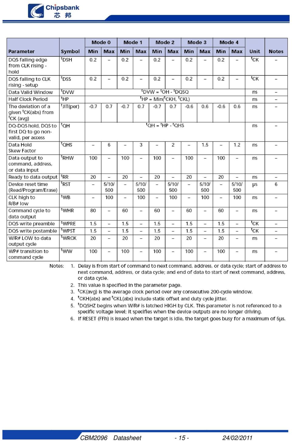
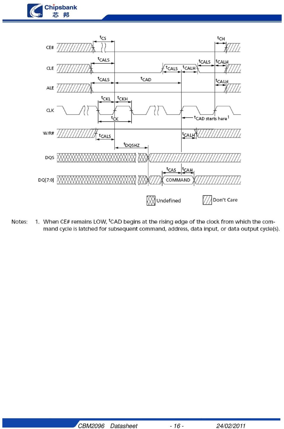
14 6.4.2 ONFI NAND FLASH Dynamic characteristics CBM2096 only support Mode0/Mode1/Mode2. CBM2096 Datasheet /02/2011

15 CBM2096 Datasheet /02/2011
16 CBM2096 Datasheet /02/2011
17 CBM2096 Datasheet /02/2011

18 CBM2096 Datasheet /02/2011

19 6.4.3 TOGGLE NAND FLASH Dynamic characteristics CBM2096 only support 66Mbps/80Mbps. CBM2096 Datasheet /02/2011

20 CBM2096 Datasheet /02/2011

21 CBM2096 Datasheet /02/2011
22 CBM2096 Datasheet /02/2011
23 CBM2096 Datasheet /02/2011
24 7 Mechanical Dimensions Pin CBM2096 Package Outline Dimension CBM2096 Datasheet /02/2011
25 8 Copyright Notice Copyright by Shenzhen Chipsbank Technologies Co.,Ltd. All Rights Reserved. Right to make changes Shenzhen Chipsbank Technologies Co.,Ltd. reserves the right to make changes in the products - including circuits, standard cells, and/or software - described or contained herein in order to improve design and/or performance. The information contained in this manual is provided for the general use by our customers. Our customers should be aware that the personal computer field is the subject of many patents. Our customers should ensure that they take appropriate action so that their use of our products does not infringe upon any patents. It is the policy of Shenzhen Chipsbank Technologies Co.,Ltd. to respect the valid patent rights of third parties and not to infringe upon or assist others to infringe upon such rights. This manual is copyrighted by Shenzhen Chipsbank Technologies Co.,Ltd. You may not reproduce, transmit, transcribe, store in a retrieval system, or translate into any language, in any form or by any means, electronic, mechanical, magnetic, optical, chemical, manual, or otherwise, any part of this publication without the expressly written permission from Shenzhen Chipsbank Technologies Co.,Ltd. CBM2096 Datasheet /02/2011
UT165 Advanced USB2.0 Flash Drive Controller
 UT165 Advanced USB2.0 Flash Drive Controller Datasheet Rev. 2.2 Jan. 29, 2008 http://www.afatech.com All rights strictly reserved. Any portion of this paper shall not be reproduced, copied, or translated
OTi. Ours Technology Inc. OTi-6828 FLASH DISK CONTROLLER. Description. Features
 Description The flash disk controller (OTi_6828) is a disk controller used to make a linear flash device array look likes a normal disk, hiding the flash related problems with erasing. The OTi_6828 is
Pen Drive 2.0 Specification
 Pen Drive 2.0 Specification Table of Contents A. General Description..2 B. Controller Outline..3 C. Features.3 D. Capacity Specification.4 E. Power Consumption.5 F. Absolute Maximum Rating...5 G. Installation
RTS5401. USB 3.0 Super-Speed HUB Controller DATASHEET. Doc Rev. 0.90 11 th Apr 2012. i Rev 0.90
 USB 3.0 Super-Speed HUB Controller DATASHEET Doc Rev. 0.90 11 th Apr 2012 i Rev 0.90 TRADEMARKS Realtek is a trademark of Realtek Semiconductor Corporation. All other names mentioned in this document are
USB Flash Drive Engineering Specification
 USB Flash Drive Engineering Specification Document Number: L5ENG00242 Revision: B No part of this document may be reproduced, stored in a retrieval system, or transmitted in any form or by any means, mechanical,
EUDAR Technology Inc. Rev. 1.0. USB 2.0 Flash Drive. with Card Reader. Datasheet. Rev. 1.0 December 2008 EUDAR 1
 EUDAR Technology Inc. Rev. 1.0 USB 2.0 Flash Drive with Card Reader Datasheet Rev. 1.0 December 2008 EUDAR 1 1 Overview EUDAR Technology Inc. Rev. 1.0 1.1 Description USB 2.0 Flash with Card Reader is
RealSSD Embedded USB Mass Storage Drive MTFDCAE001SAF, MTFDCAE002SAF, MTFDCAE004SAF, MTFDCAE008SAF
 RealSSD Embedded USB Mass Storage Drive MTFDCAE001SAF, MTFDCAE002SAF, MTFDCAE004SAF, MTFDCAE008SAF Embedded USB Mass Storage Drive Features Features Micron NAND Flash Interface: Universal Serial Bus (USB)
NTE2053 Integrated Circuit 8 Bit MPU Compatible A/D Converter
 NTE2053 Integrated Circuit 8 Bit MPU Compatible A/D Converter Description: The NTE2053 is a CMOS 8 bit successive approximation Analog to Digital converter in a 20 Lead DIP type package which uses a differential
The FT6x06 series ICs include FT6206 /FT6306, the difference of their specifications will be listed individually in this datasheet.
 FT6x06 Self-Capacitive Touch Panel Controller INTRODUCTION The FT6x06 Series ICs are single-chip capacitive touch panel controller ICs with a built-in 8 bit enhanced Micro-controller unit (MCU).They adopt
Phison PS3006 Controller
 2F, RiteKom Bldg No.669, Sec. 4, Chung Hsing Rd., Chutung, Hsinchu, Taiwan 310, R.O.C. Tel 886 3 5833899 3001 or 1001 or 1005 Fax 886 3 5833666 Phison Controller Version 1.2 1 Contents A. Features B. General
Embedded Multi-Media Card Specification (e MMC 4.5)
") Product Features: Packaged NAND flash memory with e MMC 4.5 interface Compliant with e MMC Specification Ver 4.41 & 4.5. Bus mode - High-speed e MMC protocol - Provide variable clock frequencies
Product Features: Packaged NAND flash memory with e MMC 4.5 interface Compliant with e MMC Specification Ver 4.41 & 4.5. Bus mode - High-speed e MMC protocol - Provide variable clock frequencies
Transcend Information Inc. 1. Features. Description
 Description The Transcend CF 80X is a High Speed CompactFlash Card with high quality Flash Memory assembled on a printed circuit board. Placement A Features RoHS compliant products Single Power Supply:
SX-3000EDM Integration Guide
 SX-3000EDM Integration Guide SX-3000EDM Integration Guide PN: 140-20116-110 Rev. A 1 Table of Contents SX-3000EDM Integration Guide Product Overview... 3 Introduction... 3 Features... 4 Block Diagram...
Eureka Technology. Understanding SD, SDIO and MMC Interface. by Eureka Technology Inc. May 26th, 2011. Copyright (C) All Rights Reserved
 All Rights Reserved") Understanding SD, SDIO and MMC Interface by Eureka Technology Inc. May 26th, 2011 Copyright (C) All Rights Reserved Copyright by Eureka Technology Inc. All Rights Reserved Introduction This white paper
Understanding SD, SDIO and MMC Interface by Eureka Technology Inc. May 26th, 2011 Copyright (C) All Rights Reserved Copyright by Eureka Technology Inc. All Rights Reserved Introduction This white paper
USB Flash Drive. RoHS Compliant. AH322 Specifications. July 2 nd, 2012. Version 1.2. Apacer Technology Inc. www.apacer.com
 RoHS Compliant USB Flash Drive AH322 Specifications July 2 nd, 2012 Version 1.2 Apacer Technology Inc. 4 th Fl., 75 Hsin Tai Wu Rd., Sec.1, Hsichih, New Taipei City, Taiwan 221 Tel: +886-2-2698-2888 Fax:
7 OUT1 8 OUT2 9 OUT3 10 OUT4 11 OUT5 12 OUT6 13 OUT7 14 OUT8 15 OUT9 16 OUT10 17 OUT11 18 OUT12 19 OUT13 20 OUT14 21 OUT15 22 OUT16 OUT17 23 OUT18
 18 CHANNELS LED DRIVER GENERAL DESCRIPTION IS31FL3218 is comprised of 18 constant current channels each with independent PWM control, designed for driving LEDs. The output current of each channel can be
Features. Dimensions
 Description With an IDE interface and strong data retention ability, 40-Pin IDE Flash Modules are ideal for use in the harsh environments where Industrial PCs, Set-Top Boxes, etc. are used. Placement Features
1.0. User s Guide & Manual USB 2.0 FLASH DRIVE
 1.0 USB 2.0 FLASH DRIVE User s Guide & Manual Index Introduction 1 CHAPTER1 Features & Specifications 2 CHAPTER2 System Requirements 4 CHAPTER3 Getting Started Installation of the Windows 98SE Driver 5
Industrial Semi Metal USB
 Industrial Semi Metal USB Generation 5L HERCULES-P Series Product Specification INDUSTRIAL Semi Metal USB Flash Disk Generation 5L Version 01V0 Document No. 100-xMUFD-MPT5L November 2014 APRO CO., LTD.
Features. Dimensions
 Description With an IDE interface and strong data retention ability, 40-Pin IDE Flash Modules are ideal for use in the harsh environments where Industrial PCs, Set-Top Boxes, etc. are used. Placement Features
USB Flash Drive. RoHS Compliant. AH321 Specifications. June 4 th, 2014. Version 1.4. Apacer Technology Inc. www.apacer.com
 RoHS Compliant USB Flash Drive AH321 Specifications June 4 th, 2014 Version 1.4 Apacer Technology Inc. 1F, No.32, Zhongcheng Rd., Tucheng Dist., New Taipei City, Taiwan, R.O.C Tel: +886-2-2267-8000 Fax:
VP223 USB Type-C DFP CC Controller with Universal Battery Charging
 Product Preliminary VP223 USB Type-C DFP CC Controller with Universal Battery Charging Mar. 11, 2015 VIA Labs, Inc. www.via-labs.com 7F, 529-1, Zhongzheng Rd., Xindian District, New Taipei City 231 Taiwan
Features. Dimensions
 Description With an IDE interface and strong data retention ability, 44-Pin IDE Flash Modules are ideal for use in the harsh environments where Industrial PCs, Set-Top Boxes, etc. are used. Placement Features
USB 2.0 Flash Drive User Manual
 USB 2.0 Flash Drive User Manual 1 INDEX Table of Contents Page 1. IMPORTANT NOTICES...3 2. PRODUCT INTRODUCTION...4 3. PRODUCT FEATURES...5 4. DRIVER INSTALLATION GUIDE...6 4.1 WINDOWS 98 / 98 SE... 6
ICS379. Quad PLL with VCXO Quick Turn Clock. Description. Features. Block Diagram
 Quad PLL with VCXO Quick Turn Clock Description The ICS379 QTClock TM generates up to 9 high quality, high frequency clock outputs including a reference from a low frequency pullable crystal. It is designed
S-57M1 Series HIGH-SPEED BIPOLAR HALL EFFECT LATCH. Features. Applications. Package. www.sii-ic.com
 www.sii-ic.com HIGH-SPEED BIPOLAR HALL EFFECT LATCH SII Semiconductor Corporation, 2011-2013 Rev.1.2_01 The, developed by CMOS technology, is a high-accuracy Hall IC that operates with a high-sensitivity,
Number of NAND Flash devices supported (1) up to 1 up to 4 R/W speed 11MB/s and 7MB/s 12MB/s and 8MB/s
 up to 1 up to 4 R/W speed 11MB/s and 7MB/s 12MB/s and 8MB/s") USB 2.0 high-speed Flash drive controller Not For New Design Features USB 2.0 interface compatible with mass storage device class Integrated USB 2.0 PHY supporting USB high speed and full speed Suspend
USB 2.0 high-speed Flash drive controller Not For New Design Features USB 2.0 interface compatible with mass storage device class Integrated USB 2.0 PHY supporting USB high speed and full speed Suspend
8-bit binary counter with output register; 3-state
 Rev. 3 24 February 2016 Product data sheet 1. General description The is an 8-bit binary counter with a storage register and 3-state outputs. The storage register has parallel (Q0 to Q7) outputs. The binary
Hardware Documentation. Data Sheet HAL 202. Hall-Effect Sensor. Edition Sept. 18, 2014 DSH000159_002EN
 Hardware Documentation Data Sheet HAL 202 Hall-Effect Sensor Edition Sept. 18, 2014 DSH000159_002EN HAL202 Copyright, Warranty, and Limitation of Liability The information and data contained in this document
3-to-8 line decoder, demultiplexer with address latches
 Rev. 7 29 January 2016 Product data sheet 1. General description The is a high-speed Si-gate CMOS device and is pin compatible with low-power Schottky TTL (LSTTL). The is specified in compliance with JEDEC
ICS650-01 SYSTEM PERIPHERAL CLOCK SOURCE. Description. Features. Block Diagram DATASHEET
 DATASHEET ICS650-01 Description The ICS650-01 is a low-cost, low-jitter, high-performance clock synthesizer for system peripheral applications. Using analog/digital Phase-Locked Loop (PLL) techniques,
Thermostat Application Module Kit
 Thermostat Application Module Kit PUG0040-00 Product User Guide Kit Contents Overview Thermostat Application Module CD-ROM: Software Examples and Documentation The Thermostat Application Module provides
1 TO 4 CLOCK BUFFER ICS551. Description. Features. Block Diagram DATASHEET
 DATASHEET 1 TO 4 CLOCK BUFFER ICS551 Description The ICS551 is a low cost, high-speed single input to four output clock buffer. Part of IDT s ClockBlocks TM family, this is our lowest cost, small clock
Technical Note. Micron NAND Flash Controller via Xilinx Spartan -3 FPGA. Overview. TN-29-06: NAND Flash Controller on Spartan-3 Overview
 Technical Note TN-29-06: NAND Flash Controller on Spartan-3 Overview Micron NAND Flash Controller via Xilinx Spartan -3 FPGA Overview As mobile product capabilities continue to expand, so does the demand
PACKAGE OUTLINE DALLAS DS2434 DS2434 GND. PR 35 PACKAGE See Mech. Drawings Section
 PRELIMINARY DS2434 Battery Identification Chip FEATURES Provides unique ID number to battery packs PACKAGE OUTLINE Eliminates thermistors by sensing battery temperature on chip DALLAS DS2434 1 2 3 256
74HC107; 74HCT107. Dual JK flip-flop with reset; negative-edge trigger
 Rev. 5 30 November 2015 Product data sheet 1. General description 2. Features and benefits 3. Ordering information The is a dual negative edge triggered JK flip-flop featuring individual J and K inputs,
Industrial microsd/sdhc Memory Card
 DCC Number: Industrial microsd/sdhc Memory Card Product Specification March 2011 PRETEC/C-ONE Technology Corp. Corporate Headquarters 8F, NO5, Lane 345, Yang Guang St., Neihu, Taipei,Taiwan TEL: +886-2-2659-4380
74HC377; 74HCT377. 1. General description. 2. Features and benefits. 3. Ordering information
 Rev. 4 24 February 2016 Product data sheet 1. General description 2. Features and benefits 3. Ordering information The is an octal positive-edge triggered D-type flip-flop. The device features clock (CP)
INTEGRATED CIRCUITS. For a complete data sheet, please also download:
 INTEGRATED CIRCUITS DATA SEET For a complete data sheet, please also download: The IC6 74C/CT/CU/CMOS Logic Family Specifications The IC6 74C/CT/CU/CMOS Logic Package Information The IC6 74C/CT/CU/CMOS
CD4027BMS. CMOS Dual J-K Master-Slave Flip-Flop. Pinout. Features. Functional Diagram. Applications. Description. December 1992
 CD7BMS December 199 CMOS Dual J-K Master-Slave Flip-Flop Features Pinout High Voltage Type (V Rating) Set - Reset Capability CD7BMS TOP VIEW Static Flip-Flop Operation - Retains State Indefinitely with
SSM3K335R SSM3K335R. 1. Applications. 2. Features. 3. Packaging and Pin Configuration. 2012-07-19 Rev.3.0. Silicon N-Channel MOS (U-MOS -H)
") MOSFETs Silicon N-Channel MOS (U-MOS-H) SSM3K335R SSM3K335R 1. Applications Power Management Switches DC-DC Converters 2. Features (1) 4.5-V gate drive voltage. (2) Low drain-source on-resistance : R DS(ON)
MOSFETs Silicon N-Channel MOS (U-MOS-H) SSM3K335R SSM3K335R 1. Applications Power Management Switches DC-DC Converters 2. Features (1) 4.5-V gate drive voltage. (2) Low drain-source on-resistance : R DS(ON)
GTS-4E Hardware User Manual. Version: V1.1.0 Date: 2013-12-04
 GTS-4E Hardware User Manual Version: V1.1.0 Date: 2013-12-04 Confidential Material This document contains information highly confidential to Fibocom Wireless Inc. (Fibocom). Fibocom offers this information
User Manual. EtherUSB
 User Manual EtherUSB USB Ethernet Access Point for PDA V 2.0 Clarinet Systems, Inc. Clarinet Systems, Inc. http://www.clarinetsys.com Page 1 Publication Revision No. Control Table Rev. No. Date Contents
INTEGRATED CIRCUITS. 74LVC08A Quad 2-input AND gate. Product specification IC24 Data Handbook. 1997 Jun 30
 INTEGRATED CIRCUITS IC24 Data Handbook 1997 Jun 30 FEATURES Wide supply voltage range of 1.2 V to 3.6 V In accordance with JEDEC standard no. 8-1A Inputs accept voltages up to 5.5 V CMOS low power consumption
LCM NHD-12032BZ-FSW-GBW. User s Guide. (Liquid Crystal Display Graphic Module) RoHS Compliant. For product support, contact
 RoHS Compliant. For product support, contact") User s Guide -FSW-GBW LCM (Liquid Crystal Display Graphic Module) RoHS Compliant NHD- 12032- BZ- F - SW- G- B- W- Newhaven Display 120 x 32 pixels Version Line Transflective Side White LED B/L STN- Gray
User s Guide -FSW-GBW LCM (Liquid Crystal Display Graphic Module) RoHS Compliant NHD- 12032- BZ- F - SW- G- B- W- Newhaven Display 120 x 32 pixels Version Line Transflective Side White LED B/L STN- Gray
DM9368 7-Segment Decoder/Driver/Latch with Constant Current Source Outputs
 DM9368 7-Segment Decoder/Driver/Latch with Constant Current Source Outputs General Description The DM9368 is a 7-segment decoder driver incorporating input latches and constant current output circuits
ETRX3USB ETRX3USB-LRS ETRX3USB+8M ETRX3USB-LRS+8M PRODUCT MANUAL
 Telegesis TG-ETRX357USB-PM-014-102 ETRX3USB Product Manual 1.02 ZigBee USB STICKS: ETRX3USB ETRX3USB-LRS ETRX3USB+8M ETRX3USB-LRS+8M PRODUCT MANUAL 2013 Telegesis (UK) Ltd ETRX3USB Product Manual (Rev
1 Introduction... 6. 2 Pin description... 7. 3 Application schematics... 11. 4 NAND Flash memory interface... 12. 5 Mass storage implementation...
 USB 2.0 high-speed Flash drive controller Features USB 2.0 interface compatible with mass storage device class Integrated USB 2.0 PHY Supports USB high speed and full speed Suspend and Resume operations
74HC165; 74HCT165. 8-bit parallel-in/serial out shift register
 Rev. 4 28 December 2015 Product data sheet 1. General description 2. Features and benefits 3. Applications 4. Ordering information The is an 8-bit serial or parallel-in/serial-out shift register. The device
AN-812 APPLICATION NOTE
 AN- APPLICATION NOTE One Technology Way P.O. Box 90 Norwood, MA 00-90, U.S.A. Tel: 7.9.700 Fax: 7.. www.analog.com Microcontroller-Based Serial Port Interface (SPI ) Boot Circuit by Alfredo Barriga INTRODUCTION
USB Flash Drive User s Manual
 USB Flash Drive User s Manual V4.01 Introduction Thank you for your purchasing the USB Drive. This manual will guide you through the usages of the USB Drive and of all management tools coming with it.
AND8336. Design Examples of On Board Dual Supply Voltage Logic Translators. Prepared by: Jim Lepkowski ON Semiconductor. http://onsemi.
 Design Examples of On Board Dual Supply Voltage Logic Translators Prepared by: Jim Lepkowski ON Semiconductor Introduction Logic translators can be used to connect ICs together that are located on the
LC898300XA. Functions Automatic adjustment to the individual resonance frequency Automatic brake function Initial drive frequency adjustment function
 Ordering number : A2053 CMOS LSI Linear Vibrator Driver IC http://onsemi.com Overview is a Linear Vibrator Driver IC for a haptics and a vibrator installed in mobile equipments. The best feature is it
Web Site: www.parallax.com Forums: forums.parallax.com Sales: [email protected] Technical: [email protected]
 Web Site: www.parallax.com Forums: forums.parallax.com Sales: [email protected] Technical: [email protected] Office: (916) 624-8333 Fax: (916) 624-8003 Sales: (888) 512-1024 Tech Support: (888) 997-8267
TEST CHAPTERS 1 & 2 OPERATING SYSTEMS
 TEST CHAPTERS 1 & 2 OPERATING SYSTEMS True/False Indicate whether the statement is true or false. 1. Changes that you make in virtual machines do not affect your physical computer. 2. The size of a bus
1. Description. 2. Feature. 3. PIN Configuration
 1. Description is a 9-channel LED driver control IC. Internal integrated with MCU digital interface, data flip-latch, LED high voltage driver and so on.through the external MCU control, the chip can achieve
INTEGRATED CIRCUITS. 74F153 Dual 4-line to 1-line multiplexer. Product specification 1996 Jan 05 IC15 Data Handbook
 INTEGRATED CIRCUITS 1996 Jan 05 IC15 Data Handbook FEATURES Non-inverting outputs Separate enable for each section Common select inputs See 74F253 for 3-State version PIN CONFIGURATION Ea 1 S1 2 I3a 3
User s Manual CONTENT. Nano NAS Server for USB storages. 1. Product Information...1. 2. Product Specifications.2. 3. System requirements..
 CONTENT Nano NAS Server for USB storages 1. Product Information...1 2. Product Specifications.2 3. System requirements..3 4. Product Connecting. 4 5. Configuring DN-7023....5 6. Setting... 9 7. Note..
DS1621 Digital Thermometer and Thermostat
 www.maxim-ic.com FEATURES Temperature measurements require no external components Measures temperatures from -55 C to +125 C in 0.5 C increments. Fahrenheit equivalent is -67 F to 257 F in 0.9 F increments
Future Technology Devices International Ltd
 Future Technology Devices International Ltd Datasheet UMFT200XD Breakout Modules 1 Introduction UMFT200XD is a USB to I 2 C breakout module The UMFT200XD breakout module utilizes FTDI s FT200XQ IC to convert
SD4840/4841/4842/4843/4844
 CURRENT MODE PWM CONTROLLER WITH BUILT-IN HIGH VOLTAGE MOSFET DESCRIPTION SD4840/4841/4842/4843/4844 is a current mode PWM controller with low standby power and low start current for power switch. In standby
ICS514 LOCO PLL CLOCK GENERATOR. Description. Features. Block Diagram DATASHEET
 DATASHEET ICS514 Description The ICS514 LOCO TM is the most cost effective way to generate a high-quality, high-frequency clock output from a 14.31818 MHz crystal or clock input. The name LOCO stands for
DS1821 Programmable Digital Thermostat and Thermometer
 ma www.maxim-ic.com FEATURES Requires no external components Unique 1-Wire interface requires only one port pin for communication Operates over a -55 C to +125 C (67 F to +257 F) temperature range Functions
VDIP1. Vinculum VNC1L Module. Datasheet
 Future Technology Devices International Ltd. VDIP1 Vinculum VNC1L Module Datasheet Version 1.02 Issue Date: 2010-05-31 Future Technology Devices International Ltd (FTDI) Unit 1, 2 Seaward Place, Centurion
DS1621 Digital Thermometer and Thermostat
 Digital Thermometer and Thermostat www.dalsemi.com FEATURES Temperature measurements require no external components Measures temperatures from 55 C to +125 C in 0.5 C increments. Fahrenheit equivalent
Industrial Micro SD 3.0
 RoHS Compliant Industrial Micro SD 3.0 Specifications November 3 rd, 2011 Version 1.0 Apacer Technology Inc. 4 th Fl., 75 Hsin Tai Wu Rd., Sec.1, Hsichih, New Taipei City, Taiwan 221 Tel: +886-2-2698-2888
DM74LS373/DM74LS374 3-STATE Octal D-Type Transparent Latches and Edge-Triggered Flip-Flops
 DM74LS373/DM74LS374 3-STATE Octal D-Type Transparent Latches and Edge-Triggered Flip-Flops General Description These 8-bit registers feature totem-pole 3-STATE outputs designed specifically for driving
Features. V PP IN V CC3 IN V CC5 IN (opt) EN0 EN1 MIC2562
 EN0 EN1 MIC2562") MIC2562A /CardBus Socket Power Controller General Description The MIC2562A (Personal Computer Memory Card International Association) and CardBus power controller handles all PC Card slot power supply pins,
MIC2562A /CardBus Socket Power Controller General Description The MIC2562A (Personal Computer Memory Card International Association) and CardBus power controller handles all PC Card slot power supply pins,
SATA SSD Series. InnoDisk. Customer. Approver. Approver. Customer: Customer. InnoDisk. Part Number: InnoDisk. Model Name: Date:
 SATA SSD Series Customer: Customer Part Number: InnoDisk Part Number: InnoDisk Model Name: Date: InnoDisk Approver Customer Approver Table of contents EverGreen SATA SSD REVISION HISTORY... 4 LIST OF TABLES...
ZL40221 Precision 2:6 LVDS Fanout Buffer with Glitchfree Input Reference Switching and On-Chip Input Termination Data Sheet
 Features Inputs/Outputs Accepts two differential or single-ended inputs LVPECL, LVDS, CML, HCSL, LVCMOS Glitch-free switching of references On-chip input termination and biasing for AC coupled inputs Six
Application Note AN_209. AN_209 PDIUSBD12 to FT120 Migration Guide
 AN_209 AN_209 PDIUSBD12 to FT120 Migration Guide Issue Date: 2012-12-14 The FT120 is a cost and feature optimized USB Full-Speed device controller. It communicates with a micro-controller over a generic
MicroMag3 3-Axis Magnetic Sensor Module
 1008121 R01 April 2005 MicroMag3 3-Axis Magnetic Sensor Module General Description The MicroMag3 is an integrated 3-axis magnetic field sensing module designed to aid in evaluation and prototyping of PNI
TS555. Low-power single CMOS timer. Description. Features. The TS555 is a single CMOS timer with very low consumption:
 Low-power single CMOS timer Description Datasheet - production data The TS555 is a single CMOS timer with very low consumption: Features SO8 (plastic micropackage) Pin connections (top view) (I cc(typ)
AP331A XX G - 7. Lead Free G : Green. Packaging (Note 2)
") Features General Description Wide supply Voltage range: 2.0V to 36V Single or dual supplies: ±1.0V to ±18V Very low supply current drain (0.4mA) independent of supply voltage Low input biasing current:
Features General Description Wide supply Voltage range: 2.0V to 36V Single or dual supplies: ±1.0V to ±18V Very low supply current drain (0.4mA) independent of supply voltage Low input biasing current:
DM7474 Dual Positive-Edge-Triggered D-Type Flip-Flops with Preset, Clear and Complementary Outputs
 DM7474 Dual Positive-Edge-Triggered D-Type Flip-Flops with Preset, Clear and Complementary Outputs General Description This device contains two independent positive-edge-triggered D-type flip-flops with
JTAG-HS2 Programming Cable for Xilinx FPGAs. Overview. Revised January 22, 2015 This manual applies to the HTAG-HS2 rev. A
 1300 Henley Court Pullman, WA 99163 509.334.6306 www.digilentinc.com Programming Cable for Xilinx FPGAs Revised January 22, 2015 This manual applies to the HTAG-HS2 rev. A Overview The Joint Test Action
USBSPYDER08 Discovery Kit for Freescale MC9RS08KA, MC9S08QD and MC9S08QG Microcontrollers User s Manual
 USBSPYDER08 Discovery Kit for Freescale MC9RS08KA, MC9S08QD and MC9S08QG Microcontrollers User s Manual Copyright 2007 SofTec Microsystems DC01197 We want your feedback! SofTec Microsystems is always on
MCF54418 NAND Flash Controller
 Freescale Semiconductor Application Note Document Number: AN4348 Rev. 0, 09/2011 MCF54418 NAND Flash Controller by: Liew Tsi Chung Applications Engineer 1 Introduction The ColdFire MCF5441x family is the
74HC175; 74HCT175. Quad D-type flip-flop with reset; positive-edge trigger
 Rev. 5 29 January 2016 Product data sheet 1. General description 2. Features and benefits 3. Ordering information The is a quad positive-edge triggered D-type flip-flop with individual data inputs (Dn)
HEF4011B. 1. General description. 2. Features and benefits. 3. Ordering information. 4. Functional diagram. Quad 2-input NAND gate
 Rev. 6 10 December 2015 Product data sheet 1. General description 2. Features and benefits 3. Ordering information The is a quad 2-input NAND gate. The outputs are fully buffered for the highest noise
Develop a Dallas 1-Wire Master Using the Z8F1680 Series of MCUs
 Develop a Dallas 1-Wire Master Using the Z8F1680 Series of MCUs AN033101-0412 Abstract This describes how to interface the Dallas 1-Wire bus with Zilog s Z8F1680 Series of MCUs as master devices. The Z8F0880,
udrive-usd-g1 Embedded DOS micro-drive Module Data Sheet
 4D SYSTEMS udrie-usd-g1 Embedded DOS micro-drive Module Document Date: 2nd April 2009 Document Revision: 2.0 Page 1 of 9 udrie-usd-g1 Embedded DOS micro-drive 4D SYSTEMS Description Features The is an
DS1220Y 16k Nonvolatile SRAM
 Not Recommended for New Design DS122Y 16k Nonvolatile SRAM www.maxim-ic.com FEATURES years minimum data retention in the absence of external power Data is automatically protected during power loss Directly
MM74HC273 Octal D-Type Flip-Flops with Clear
 MM74HC273 Octal D-Type Flip-Flops with Clear General Description The MM74HC273 edge triggered flip-flops utilize advanced silicon-gate CMOS technology to implement D-type flipflops. They possess high noise
74HC4040; 74HCT4040. 12-stage binary ripple counter
 Rev. 5 3 February 2016 Product data sheet 1. General description 2. Features and benefits 3. Applications 4. Ordering information The is a with a clock input (CP), an overriding asynchronous master reset
MC33064DM 5 UNDERVOLTAGE SENSING CIRCUIT
 Order this document by MC3464/D The MC3464 is an undervoltage sensing circuit specifically designed for use as a reset controller in microprocessor-based systems. It offers the designer an economical solution
AN2680 Application note
 Application note Fan speed controller based on STDS75 or STLM75 digital temperature sensor and ST72651AR6 MCU Introduction This application note describes the method of defining the system for regulating
CD4027BC Dual J-K Master/Slave Flip-Flop with Set and Reset
 October 1987 Revised March 2002 CD4027BC Dual J-K Master/Slave Flip-Flop with Set and Reset General Description The CD4027BC dual J-K flip-flops are monolithic complementary MOS (CMOS) integrated circuits
DS1225Y 64k Nonvolatile SRAM
 DS1225Y 64k Nonvolatile SRAM www.maxim-ic.com FEATURES years minimum data retention in the absence of external power Data is automatically protected during power loss Directly replaces 2k x 8 volatile
DMX-K-DRV. Integrated Step Motor Driver + (Basic Controller) Manual
 Manual") DMX-K-DRV Integrated Step Motor Driver + (Basic Controller) Manual DMX-K-DRV Manual page 1 rev 1.33 COPYRIGHT 2007 ARCUS, ALL RIGHTS RESERVED First edition, June 2007 ARCUS TECHNOLOGY copyrights this document.
DMX-K-DRV Integrated Step Motor Driver + (Basic Controller) Manual DMX-K-DRV Manual page 1 rev 1.33 COPYRIGHT 2007 ARCUS, ALL RIGHTS RESERVED First edition, June 2007 ARCUS TECHNOLOGY copyrights this document.
Features. Modulation Frequency (khz) VDD. PLL Clock Synthesizer with Spread Spectrum Circuitry GND
 VDD. PLL Clock Synthesizer with Spread Spectrum Circuitry GND") DATASHEET IDT5P50901/2/3/4 Description The IDT5P50901/2/3/4 is a family of 1.8V low power, spread spectrum clock generators capable of reducing EMI radiation from an input clock. Spread spectrum technique
DATASHEET IDT5P50901/2/3/4 Description The IDT5P50901/2/3/4 is a family of 1.8V low power, spread spectrum clock generators capable of reducing EMI radiation from an input clock. Spread spectrum technique
14-stage ripple-carry binary counter/divider and oscillator
 Rev. 8 25 March 2016 Product data sheet 1. General description 2. Features and benefits 3. Ordering information The is a with three oscillator terminals (RS, REXT and CEXT), ten buffered outputs (Q3 to
EMERGING DISPLAY CUSTOMER ACCEPTANCE SPECIFICATIONS 16290(LED TYPES) EXAMINED BY : FILE NO. CAS-10251 ISSUE : JUL.03,2001 TOTAL PAGE : 7
 EXAMINED BY : FILE NO. CAS-10251 ISSUE : JUL.03,2001 TOTAL PAGE : 7") EXAMINED BY : FILE NO. CAS-10251 EMERGING DISPLAY ISSUE : JUL.03,2001 APPROVED BY: TECHNOLOGIES CORPORATION TOTAL PAGE : 7 VERSION : 1 CUSTOMER ACCEPTANCE SPECIFICATIONS MODEL NO. : 16290(LED TYPES) FOR
EXAMINED BY : FILE NO. CAS-10251 EMERGING DISPLAY ISSUE : JUL.03,2001 APPROVED BY: TECHNOLOGIES CORPORATION TOTAL PAGE : 7 VERSION : 1 CUSTOMER ACCEPTANCE SPECIFICATIONS MODEL NO. : 16290(LED TYPES) FOR
74HC574; 74HCT574. Octal D-type flip-flop; positive edge-trigger; 3-state
 Rev. 7 4 March 2016 Product data sheet 1. General description 2. Features and benefits 3. Ordering information The is an 8-bit positive-edge triggered D-type flip-flop with 3-state outputs. The device
TOSHIBA Bipolar Linear Integrated Circuit Silicon Monolithic TAR5SB15~TAR5SB50
 TOSHIBA Bipolar Linear Integrated Circuit Silicon Monolithic TARSB~TARSB Point Regulators (Low-Dropout Regulator) TARSB~TARSB The TARSBxx Series is comprised of general-purpose bipolar single-power-supply
BIPOLAR ANALOG INTEGRATED CIRCUIT
 DATA SHEET BIPOLAR ANALOG INTEGRATED CIRCUIT μpc8tk SiGe:C LOW NOISE AMPLIFIER FOR GPS/MOBILE COMMUNICATIONS DESCRIPTION The μpc8tk is a silicon germanium carbon (SiGe:C) monolithic integrated circuit
74HC238; 74HCT238. 3-to-8 line decoder/demultiplexer
 Rev. 4 27 January 2016 Product data sheet 1. General description 2. Features and benefits 3. Ordering information The decodes three binary weighted address inputs (A0, A1 and A2) to eight mutually exclusive
AN111: Using 8-Bit MCUs in 5 Volt Systems
 This document describes how to incorporate Silicon Lab s 8-bit EFM8 and C8051 families of devices into existing 5 V systems. When using a 3 V device in a 5 V system, the user must consider: A 3 V power