Digital Ignition ZDG3
|
|
|
- Kenneth Pearson
- 9 years ago
- Views:
Transcription
1 Digital Ignition ZDG3 Fitting instructions for digital ignition ZDG3 for Moto Guzzi available for Bosch, Ducati or Saprisa alternators 1. Function 2. Fitting 3. Electrical connection 4. Adjustments 5. General Volker Sachse Lerchenweg 12 D32312 Lübbecke /61188

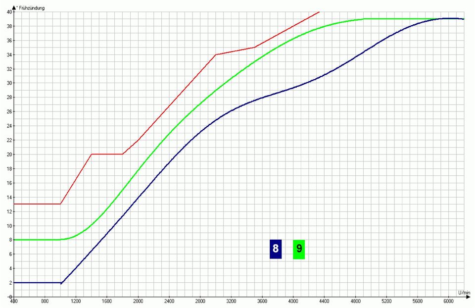
2 Fitting instructions digital ignition ZDG3 for Moto Guzzi 1. Function - 2. Fitting - 3. Electrical connection - 4.Adjustment - 5. General The digital ignition ZDG3 consists of the following components: - light-barrier printed circuit board - corresponding mechanical parts - the ignition box By the assembly at the crankshaft the distributor with the contact breakers or Motoplat pickups becomes redundant. Function: per revolution of the crankshaft starting from TDC, the momentary peripheral speed is determined and by this means, the time up to ignition is calculated. Because the peripheral speed varies substantially during acceleration, this long measurement is selected in order to determine a relatively exact measurement. The following computation of ignition timing is divided into 4 ranges: rpm Starting range, ignition always at TDC rpm Idling range, 2 to 8 advanced ignition, depending on curve selection rpm Partial load range, the spark advance adjustment occurs here rpm maximum load range, constant 30 to 34 advanced ignition, depending on curve selection As opposed to the original ignition system, ignition now takes place at each revolution of the crankshaft, thus also during the exhaust stroke. That is because of the fact that at the crankshaft between work and exhaust stroke cannot be differentiated. ignition box pulse disc and tappet light-barrier printed circuit board The measuring happens by opto-electronic parts - light barriers - because only light barriers produces an always same, speed-independent precise signal and therefore all computations can be made more accurately. Unlike other ignition systems, here each cylinder has a self-sufficient ignition, i.e. two micro-controllers for two cylinders, thus two light-barriers. This has the advantage that the advanced ignition is precisely computed for each cylinder. Thus, this ignition can also be used with one-cylinder models, by leaving one channel unconnected. If the engine stops, the ignition current will be switched off after 3 sec. to protect the ignition coils. 9 ignition curves are available: (No. 6 and 7 foe double ignition )

3 Fitting instructions digital ignition ZDG3 for Moto Guzzi 1. Function - 2.Fitting - 3. Electrical connection - 4. Adjustment - 5. General DUCATI-Alternator: BOSCH-Alternator: First remove the generator cover and the bottom and left-hand (in driving direction) stator screws. Screw the two M5-screws with washers into the threaded bolts and also the threaded rods on the other side. In this way the rods can be installed surely. After the tighten of the threaded bolts remove the screws again. Next, remove the middle screw of the rotor. If necessary block the crankshaft by placing a large screwdriver through the ignition inspection opening of the gearbox. Then fit the driver with the screw (without washer) again. Next fit the pulse disc onto the driver. The grub screws should not yet be tightened. Finally, fit the pickup PCB (printed circuit board) to the threaded bolts by means of the two M5 screws. Ensure that the pulse disc is the center of the light-barrier. With a little patience and talcum powder the Pickup cable can be pushed also through the rubber sleeve. Otherwise an additional groove must be made next to the rubber sleeve for the pickup-cable seal-ring on the generator cover. When fitting the generator cover, two 6mm washers must be

4 placed on each of the four screws between the cover and ring to ensure that the pulse disc does not scrape the cover. Usually only one is necessary, but this should be checked in each individual case. Tip: this distance can be tested by placing a little plasticine or putty on the pulse disc.

5 Fitting instructions digital ignition ZDG3 for Moto Guzzi 1. Function - 2. Fitting - 3. Electrical connection - 4. Adjustment - 5. General Ignition circuit diagram, Motoplat replacement The conductor crosssection of the ground wire should amount to 1,5-2,5 mm2 and schould be kept as short as possible. The conductor crosssection of the other cables should not be below 0,75 mm2. Always use end splices! Ignition circuit diagram, contact breaker replacement Connection allocation of the system plug 1 ignition coil for left-hand cylinder 2 ground (ensure good contact to the frame!) 3 brown, ground (Pickup) 4 green, barrier P2 (l.h. cylinder) (Pickup) 5 yellow, barrier P1 (r.h. cylinder) (Pickup) 6 white, +5V (Pickup) 7 connector for the electronic rev. counter (if used) The original ignition coils can be used further, but when new ones will be mounted the only technical requirement is a primary resistance of 2,5-8 Ohm (measured between the connectors) Double ignition coils 2,5-3,5 Ohm

6 8 +12V (12V supply voltage from the ignition switch, e.g. ignition coil 15 or +) 9 ground 10 ignition coil for right-hand cylinder
 9 ground")
7 Fitting instructions digital ignition ZDG3 for Moto Guzzi 1. Function - 2. Fitting - 3. Electrical connection - 4. Adjustment - 5. General Attention! Remove the spark plug caps before adjusting the pulse disc! First, bring the right piston to TDC (D marking on the flywheel). Now rotate the pulse disc precisely into the position as shown in the picture. The position is correct when the LED (red circle) toggles. Now tighten the grub screws evenly and replace the spark plug caps. The bike is ready to start. Finally, check the ignition timing with a timing light and if necessary, correct the position of the pulse disc. Ensure that the pulse disc is in the centre of the lightbarrier! The switches can be found at the front of the ignition box: switch adjustment rotary switch (curve selectionl) 1-9 curves test mode, continuous firing 2 DIP switch overspeed protection at 7900 rpm (switch down) or at 9800 rpm (switch up) rev. counter frequency (switch up >> fout =crankshaft switch down >> fout=camshaft )

8 Fitting instructions digital ignition ZDG3 for Moto Guzzi 1. Function - 2.Fitting - 3. Electrical connection - 4. Adjustment - 5. General Only use interference-free spark plug caps! (recommended NGK caps with 5kOhm internal resistance) Malfunction sources : Unstable ignition timing : At some stroboscope lamps the ignition point suddenly oscillates around 4-6. In this case the lamp once reacts to the ignition spark starting, another time to the burning end of the spark. If possible readjust the sensitivity of the lamp or take another timing lamp. Doesn't start : If the engine should not start, or the starting procedure is suddenly strangled, then the ignition coils are mixed up. If so, swap the ignition cables which lead to the spark plugs or reconnect the ignition coils. You can check the function of the ignition by unscrewing the spark plugs, leaving them in the plugs and connect to ground. Now start the engine with an attached timing lamp and check the ignition timing. Because of the missing spark plugs the engine runs fast enough to see a stable ignition at TDC. To check the cable connecting and the supply voltage put the rotary switch to '0'. Now the spark plugs must fire continually. If the engine should not start with slowly turning starter, probably the battery voltage falls under the minimum supply voltage of the ignition (approx. 7V). Sporadic engine cutout : If sometimes the engine suspends for 2-3 seconds while driving and keeps running thereafter normally that means that the ignition has been reset. The causes of this malfunktion could be a broken spark plug connector or a loose ignition cable. But in most cases a bad connection to the operating voltage supply causes this effect (starter lock, fuse holder etc.). For testing you can connect a wire directly from the ignition box power supply to the positive terminal of the battery. If the ignition now runs perfect, you've got an malfunction in the wiring harness. With points such a malfunction is not noticeable, because a short break of the power supply doesn't matter. In contrast electronics are very sensitive to weak power supplies. Volker Sachse Motorcycle Electronics Lerchenweg Luebbecke Germany Tel /61188 Mobil: / [email protected]

9

10
11 Fitting instructions digital ignition ZDG3 for Moto Guzzi 1. Function - 2.Fitting - 3. Electrical connection - 4. Adjustment - 5. General DUCATI-Alternator: First remove the generator cover and the central nut of the rotor. Then srew the driver onto the thread. Tighten the driver with a screw driver through the boreholes. In case of M16 thread use also the big washer. Next remove the bottom and left-hand (in driving direction) stator screws. Screw the two M5-screws with washers into the threaded bolts and also the threaded rods into the other side. In this way the rods can be installed surely. After the tighten of the threaded bolts remove the M5-screws again. Next fit the pulse disc onto the driver. The grub screws should not yet be tightened. Finally, fit the pickup PCB (printed circuit board) to the threaded bolts by means of the two M5 screws. Ensure that the pulse disc is the center of the light-barrier.

12 With a little patience and talcum powder the Pickup cable can be pushed also through the rubber sleeve. Otherwise an additional groove must be made next to the rubber sleeve for the pickup-cable seal-ring on the generator cover. The alternator cover should be set on distance with washers or nuts. The right distance should be checked in each individual case. Tip: this distance can be tested by placing a little plasticine or putty on the pulse disc.

13 Fitting instructions for digital ignition ZDG3 for BMW 1. Function - 2. Mounting - 3. Electr. connection (6V coils/di) - 4. Electr. connection (12V coils) - 4. Adjustment - 5. General electrical connection with two 6V coils (original equipment) electrical connection with a double ignition coil
")
14 1 not connected Connection allocation of the system plug 2 ground (Make sure of a good contact to the frame!!) 3 brown, ground (Pickup) 4 not connected 5 yellow, light barrier (Pickup) 6 white, +5V (Pickup) 7 tachometer output 8 +12V (Supply voltage from the ignition switch) The conductor cross-section of the ground wire should amount to 1,5-2,5 mm2 and schould be kept as short as possible. The conductor cross-section of the other cables should not be below 0,75 mm2. Always use end splices! 9 ground 10 ignition coil

FUEL-16, Troubleshooting Fuel Supply Problems
 FUEL-16, Troubleshooting Fuel Supply Problems Introduction This procedure is used to troubleshooting fuel supply problems including failure of the fuel pump to start during engine cranking. Fuel Pump Not
12-Volt Negative Ground Installation Instructions
 12-Volt Negative Ground Installation Instructions For Part Number: 1141, 1164, 1165, 1181 CAUTION!!! Before installing, please read the following important information... 1. The Ignitor is designed for
KVT-729DVD INSTALLATION MANUAL
 MONITOR WITH DVD RECEIVER KVT-729DVD INSTALLATION MANUAL B54-4516-00/00 (EV) Accessories 1 0...1...1 2!...1...2 3...1 4 5...1...1 6...2 7...4 8...4 9...2 2 KVT-729DVD Installation Procedure 1. To prevent
MARK-3 DIS Digital Ignition Solution
 Overview: MARK-3 DIS Digital Ignition Solution WATERAX offers a conversion kit Digital Ignition Solution (DIS) for users that want to convert a MARK-3 from breaker points and mechanical cut-out switch
cbperformance.com Please read this entire brochure prior to installing your CB Performance Products MAGNASPARK II distributor.
 - Easy -wire installation with no external spark box necessary, but can be used with one. - Precision CNC machining and hand assembled construction. This is a premium product. - Accurate super hot spark
CAUTION: CAREFULLY READ INSTRUCTIONS BEFORE PROCEEDING. NOT LEGAL FOR SALE OR USE IN CALIFORNIA OR ON ANY POLLUTION CONTROLLED VEHICLES.
 Twin Tec Installation Instructions for Twin Cam Ignition CAUTION: CAREFULLY READ INSTRUCTIONS BEFORE PROCEEDING. T LEGAL FOR SALE OR USE IN CALIFORNIA OR ON ANY POLLUTION CONTROLLED VEHICLES. OVERVIEW
Describe the procedure used to check for spark. Discuss what to inspect and look for during a visual inspection of the ignition system.
 CHAPTER 20 OBJECTIVES Describe the procedure used to check for spark. Discuss what to inspect and look for during a visual inspection of the ignition system. List the steps necessary to check and/or adjust
Flextec 450 PARTS LIST FOR RETURN TO MAIN INDEX
 Illustration of Sub Assemblies Illustration of Sub Assemblies Illustration of Sub Assemblies Illustration of Sub Assemblies P-652 RETURN TO MAIN INDEX PARTS LIST FOR Flextec 450 P-652 P-652-A P-652-A ILLUSTRATION
SECTION G2: CABLE PROCESSOR MODULE MAINTENANCE
 SECTION G2: CABLE PROCESSOR MODULE MAINTENANCE Cable Processor Module overview WARNING! When tipping the Cable Processor Module back, (after removing the toggle arm pin), use extreme caution not to drop
17. LIGHTS/INSTRUMENTS/SWITCHES
 17 SERVICE INFORMATION... 17-0 IGNITION SWITCH... 17-3 TROUBLESHOOTING... 17-0 STOP SWITCHES/HORN... 17-4 FUEL UNIT... 17-1 INSTRUMENTS... 17-4 HANDLEBAR SWITCHES... 17-2 HEADLIGHT/LIGHTS... 17-5 17 SERVICE
1/29/2008 DR70. Baja Motorsports Inc. P.O. Box 61150 Phoenix, AZ 85082 Toll Free: 888-863-2252 PART NUMBERS PRICES ARE SUBJECT TO CHANGE 1 of 43
 DR70 Toll Free: 888-863-2252 PART NUMBERS PRICES ARE SUBJECT TO CHANGE 1 of 43 CYLINDER & CYLINDER HEAD 1 DR70-001 883099044472 CYLINDER 1 1 2 DR70-002 883099044489 GASKET, CYLINDER 1 1 3 DR70-003 883099044496
PARTS MANUAL EH12-2 ENGINE. Model. PUB-EP5713 Rev. 7/99
 PARTS MANUAL Model EH12-2 ENGINE PUB-EP5713 Rev. 7/99 940 Lively Blvd. Wood Dale, IL 60191 Phone: 630-350-8200 Fax: 630-350-8212 e-mail: [email protected] www.robinamerica.com Copyright 1999 Robin
Owner s Manual Ignition Upgrade Module for 2004-up Carbureted Harley Davidson Motorcycles P/N ASM5075
 Owner s Manual Ignition Upgrade Module for 2004-up Carbureted Harley Davidson Motorcycles P/N ASM5075 Thunder Heart Performance Corporation MANUAL P/N EI5075 120 Industrial Drive Revision 7/15/05 White
Installation instructions for the '123ignition'
 Installation instructions for the '123ignition' type for : 123\VW-R & 123\VW-R-V : VW types 1,2&3,181,Porsche 356, Porsche 912 & tuning engines for 6 or 12 Volt cars, negative earth only. IMPORTANT Please
13. REAR WHEEL/BRAKE/SUSPENSION
 13. REAR WHEEL/BRAKE/SUSPENSION 13 3.5~4.5kg-m 8.0~10.0kg-m 0.8~1.2kg-m 3.0~4.0kg-m 2.4~3.0kg-m 3.5~4.5kg-m 6.0~8.0kg-m 13-0 13. REAR WHEEL/BRAKE/SUSPENSION 13 REAR WHEEL/BRAKE/SUSPENSION SERVICE INFORMATION...
SERVICE BULLETIN No.1103
 SERVICE BULLETIN No.1103 Circulate to listed addressees COACH MODEL BULLETIN TYPE MANUAL & SECTION PARTS BOOK REVISION : T 2100 and C2000 Series : Service Information : Maintenance Manual: Chapter 3 Drive
EASY START SYSTEM. Toni Clark practical scale GmbH EASY START SYSTEM 1
 1 GB Toni Clark practical scale GmbH 2 2 INSTALLATION: Unplug the connector in the red lead from power coil to spark coil. Push the round plug of the Easy Start into the power coil s red lead connector.
UNIT 3 AUTOMOBILE ELECTRICAL SYSTEMS
 UNIT 3 AUTOMOBILE ELECTRICAL SYSTEMS Automobile Electrical Structure 3.1 Introduction Objectives 3.2 Ignition System 3.3 Requirement of an Ignition System 3.4 Types of Ignition 3.4.1 Battery or Coil Ignition
ENGINE ELECTRICAL SYSTEM
 ENGINE ELECTRICAL SYSTEM Return To Main Table of Contents GENERAL... 2 IGNITION SYSTEM... 4 CHARGING SYSTEM... 21 STARTING SYSTEM... 38 GENERAL GENERAL SPECIFICATIONS Distributor MPI FBC Type Contact pointless
1/29/2008 DR50. Baja Motorsports Inc. P.O. Box 61150 Phoenix, AZ 85082 Toll Free: 888-863-2252 PART NUMBERS PRICES ARE SUBJECT TO CHANGE 1 of 45
 DR50 Toll Free: 888-863-2252 PART NUMBERS PRICES ARE SUBJECT TO CHANGE 1 of 45 CYLINDER & CYLINDER HEAD Part UPC Number Description Baja Description 1 DR50-001 842645074424 CYLINDER 1 1 2 DR50-002 842645074431
INSTRUCTIONS FOR THE INSTALLATION AND OPERATION OF ACTIVATOR II
 INSTRUCTIONS FOR THE INSTALLATION AND OPERATION OF ACTIVATOR II ELECTRONIC TRAILER BRAKE CONTROL 5500 FOR 2, 4, 6 & 8 BRAKE SYSTEMS IMPORTANT: READ AND FOLLOW THESE INSTRUCTIONS CAREFULLY. KEEP THESE INSTRUCTIONS
DR90. Baja Motorsports Inc. P.O. Box 61150 Phoenix, AZ 85082 Toll Free: 888-863-2252 PART NUMBERS AND PRICES ARE SUBJECT TO CHANGE 1 of 51
 DR90 Toll Free: 888-863-2252 PART NUMBERS AND PRICES ARE SUBJECT TO CHANGE 1 of 51 CYLINDER & CYLINDER HEAD 1 DR90-001 842645048166 CYLINDER 1 1 2 DR90-002 842645048173 GASKET, CYLINDER 1 1 3 DR90-003
Assembly Instructions for GUZZI
 Assembly Instructions for GUZZI Hall sensor E_MG_PB_5FH_38 (c)sep.2014 30. September 2014 SILENT HEKTIK Hansastr. 72b D-59425 Unna T. (+49) 02303-257070 F. (+49) 02303-257071 www.silent-hektik.com Page
DESCRIPTION. DTC P0351 Ignition Coil "A" Primary / Secondary Circuit. DTC P0352 Ignition Coil "B" Primary / Secondary Circuit
 1 of 10 6/4/2012 10:38 PM Last Modified: 3-27-2012 6.4 C From: 201203 Model Year: 2013 Model: FR-S Doc ID: RM000000XH40PUX Title: FA20 ENGINE CONTROL: SFI SYSTEM: P0351-P0354: Ignition Coil "A" Primary
TABLE OF CONTENTS. I. TROUBLESHOOTING... 2 - Section 1.01: Common Problems/Solutions... 2
 BAL Accu-Slide System I. Table of Contents TABLE OF CONTENTS I. TROUBLESHOOTING... 2 - Section 1.01: Common Problems/Solutions... 2 II. GETTING STARTED... 5 - Section 2.01: Tools You Will Need... 5 - Section
MSD Pro-Billet Ready-to-Run Chevrolet V8 Distributor, PN 8360 Chevrolet 348, 409 Distributor, PN 8393
 MSD Pro-Billet Ready-to-Run Chevrolet V8 Distributor, PN 8360 Chevrolet 348, 409 Distributor, PN 8393 ONLINE PRODUCT REGISTRATION: Register your MSD product online and you ll be entered in our monthly
DR90. Baja Motorsports Inc. P.O. Box 61150 Phoenix, AZ 85082 Toll Free: 888-863-2252 PART NUMBERS AND PRICES ARE SUBJECT TO CHANGE 1 of 51
 DR90 Toll Free: 888-863-2252 PART NUMBERS AND PRICES ARE SUBJECT TO CHANGE 1 of 51 CYLINDER & CYLINDER HEAD Part UPC Number Description Baja Description 1 DR90-001 842645048166 CYLINDER 1 1 2 DR90-002
Time needed: ~3h for lid replacement only. Add 1h for operation harness in lid and ~2h more for installing drive unit and cable harness in trunk.
 DIY for replacing trunk lid and/or retrofitting electrical operation of trunk lid. This document is meant to be a support and give advice on the procedure but I will take no responsibility for any damage
1955-1956 Chevy Bel-Era
 Classic Instruments 1955-1956 Chevy Bel-Era Installation Manual Revised January 2, 2014 Page 1 Table of Contents Table of Contents 2 Welcome to the Team of Classic Instruments! 3 55-56 Chevy Part Identification
DR50 Hensim Dirt Runner 49cc Dirt Bike (VIN PREFIX LLCH or LUAH)
") Page 1 of 21 Product Information Baja Web > Product Information > Parts Lists > DIRTBIKE > DR50 Hensim Dirt Runner 49cc Dirt Bike (VIN PREFIX LLCH or LUAH) DR50 Hensim Dirt Runner 49cc Dirt Bike (VIN PREFIX
Page 1 of 21 Product Information Baja Web > Product Information > Parts Lists > DIRTBIKE > DR50 Hensim Dirt Runner 49cc Dirt Bike (VIN PREFIX LLCH or LUAH) DR50 Hensim Dirt Runner 49cc Dirt Bike (VIN PREFIX
INSTALL/REMOVAL INSTRUCTIONS: WINDOW REGULATOR
 REMOVAL/INSTALL OF WINDOW REGULATOR (741-306) Honda Accord 2003 07 General Tech Tips: Use painter s tape rather than duct tape to secure window. It will not damage paint or leave sticky residue. A plastic
Remote Head REMO ONE. Code 5750. Manual
 Remote Head REMO ONE Code 5750 Manual by sachtler. All rights reserved Version: 1.2/09/05 Issue date: September 2005 Order no.: srh20t010a We want you to receive Sachtler products that are always state
Permanent Magnet Motor Kit, Magnetic Reed Type. (SKY-ReedMotorKit) Instructions
 Instructions") Permanent Magnet Motor Kit, Magnetic Reed Type (SKY-ReedMotorKit) Instructions This kit contains powerful permanent magnets. Exercise caution when handling them as they can pull on iron tools and snap
Permanent Magnet Motor Kit, Magnetic Reed Type (SKY-ReedMotorKit) Instructions This kit contains powerful permanent magnets. Exercise caution when handling them as they can pull on iron tools and snap
Magneto Timing. The selected wire(s) from the magneto(s) distributor must be connected to this cylinder. And the crankshaft/magneto must be spinning.
 from the magneto(s) distributor must be connected to this cylinder. And the crankshaft/magneto must be spinning.") Magneto Timing The two areas of timing a magneto are internal, and external. A number of things must occur at the same time, or in a well orchestrated sequence for the engine to function. Magneto Timing
Magneto Timing The two areas of timing a magneto are internal, and external. A number of things must occur at the same time, or in a well orchestrated sequence for the engine to function. Magneto Timing
11. März 2015. SILENT HEKTIK Hansastr. 72b D-59425 Unna T. (+49) 02303-257070 F. (+49) 02303-257071 www.silent-hektik.
 02303-257070 F. (+49) 02303-257071 www.silent-hektik.") Assembly Instructions for 2V-Boxer Induktive on dynamo E_B_PB_5FI_46 (c)sep.2014 11. März 2015 SILENT HEKTIK Hansastr. 72b D-59425 Unna T. (+49) 02303-257070 F. (+49) 02303-257071 www.silent-hektik.com
Assembly Instructions for 2V-Boxer Induktive on dynamo E_B_PB_5FI_46 (c)sep.2014 11. März 2015 SILENT HEKTIK Hansastr. 72b D-59425 Unna T. (+49) 02303-257070 F. (+49) 02303-257071 www.silent-hektik.com
2003 Audi A4. AUDI' '3.0L V6 - AVK Engine - A4 & A6
 Installation (A4) CAUTION: Before installation, ensure camshafts are aligned, crankshaft is locked in place and camshaft gear bolts are loose as described in removal procedures. When turning camshaft,
DTC P0351 Ignition Coil "A" Primary / Secondary Circuit. DTC P0352 Ignition Coil "B" Primary / Secondary Circuit
 208 2UZ-FE EINE CONTROL SYSTEM SFI SYSTEM DTC P05 Ignition Coil "A" Primary / Secondary Circuit DTC P052 Ignition Coil "B" Primary / Secondary Circuit DTC P05 Ignition Coil "C" Primary / Secondary Circuit
...een product van BEKA
 Integrated electric controller S-EP with Hirschmann connector Contents Page EP- pump with integrated controller S-EP Algemeen. Functional features. Time control -. Stroke control Supplementary functions.
Multi-Protocol decoder 76 200 with Load regulation
 Multi-Protocol decoder 76 2 with Load regulation For locomotives with universal motors on digital layouts operating in the DCC and Motorola data format. Features 76 2 Load regulated multi-protocol decoder
PUSH BUTTON START INSTALLATION MANUAL
 PUSH BUTTON START INSTALLATION MANUAL ALTHOUGH THIS PRODUCT HAS BEEN THOROUGHLY TESTED KPIERSON TECHNOLOGIES ASSUMES NO RESPONSIBILITY FOR ANY DAMAGE THAT MAY RESULT BY THE INSTALLATION OF THIS PRODUCT.
MGA Alternator Conversion
 MGA Alternator Conversion Installation Instructions For 1955 to 1962 MGA PART # 130-078 and #130-088 440 Rutherford St. P.O. Box 847 Goleta, CA 93117 1-800-667-7872 FAX 805-692-2525 www.mossmotors.com
Fitting Instruction: Daytona 675 Street Triple from VIN 411984, Street Triple R from VIN 411984 A9930222
 English Fitting Instruction: Daytona 675 Street Triple from VIN 98, Street Triple R from VIN 98 A990 Thank you for choosing this Triumph genuine accessory kit. This accessory kit is the product of Triumph's
BR150 Pmi Baja Reaction 150cc Go Kart (VIN PREFIX L4VM)
") Page 1 of 21 Product Information Baja Web > Product Information > Parts Lists > GOKART > BR150 Pmi Baja Reaction 150cc Go Kart (VIN PREFIX L4VM) BR150 Pmi Baja Reaction 150cc Go Kart (VIN PREFIX L4VM)
Page 1 of 21 Product Information Baja Web > Product Information > Parts Lists > GOKART > BR150 Pmi Baja Reaction 150cc Go Kart (VIN PREFIX L4VM) BR150 Pmi Baja Reaction 150cc Go Kart (VIN PREFIX L4VM)
Installation Instructions
 520 Installation Instructions Thank you very much for purchasing PIAA product. Please read this entire manual before installation and use of this product. For Installers Please give this Installation Manual
Triac Printed Circuit Board Replacement
 Technical Service Bulletin: Triac Printed Circuit Board Replacement TRONIC 5000C Pro Models: WH17, WH27, WH36 Introduction Fig. 1 ELECTRICITY IS EXTREMELY DANGEROUS. TAKE EXTRA PRECAUTIONS AND ENSURE ALL
Ignition Installation Troubleshooting Tips/Frequently-Asked Questions
 Ignition Installation Troubleshooting Tips/Frequently-Asked Questions Warning: Reversing the red and black ignition wires will destroy the ignition module and void the warranty. The Hot-Spark module s
Installation & User Manual Radio Remote rev1.0.3
 EN Installation & User Manual Radio Remote rev1.0.3 RC-20E RC-21E RC-22E RC-23E SLEIPNER MOTOR AS P.O. Box 519 N-1612 Fredrikstad Norway Tel: +47 69 30 00 60 Fax: +47 69 30 00 70 www.side-power.com [email protected]
Understanding Generator Ripple Waveforms
 Understanding Generator Ripple Waveforms 2 Understanding Generator Ripple Waveforms Chapter Page Preliminary Information and Setup 3 Generator Theory 6 Generator Ripple Theory 15 Factors that Influence
2740 Whitten Rd Bldg 103 Memphis, TN 38133 Telephone 901-380-9290 Email [email protected]
 Fuel Injection Pump Replacement REMOVAL Diesel Care & Performance Inc 1. Disconnect negative battery terminal. 2. Remove throttle linkage. Fuel Injection Pump Bracket 3. Remove injection pump bracket.
User Manual. Instructions for installing the Sure Stitch on the Next Generation Quilting Frame. Parts Included:
 User Manual Instructions for installing the Sure Stitch on the Next Generation Quilting Frame. Parts Included: 1: Display Console 1: Control Box 2: Encoder (Wires attached) (Not Shown) 1: 5v Power Supply
Vehicle Power Install Kit
 Vehicle Power Install Kit Installation Instructions Intermec Technologies Corporation Worldwide Headquarters 6001 36th Ave.W. Everett, WA 98203 U.S.A. www.intermec.com The information contained herein
1/29/2008 DR125 / DR150. Baja Motorsports Inc. P.O. Box 61150 Phoenix, AZ 85082 Toll Free: 888-863-2252 PARTS AND PRICES ARE SUBJECT TO CHANGE 1 of 55
 DR125 / DR150 Toll Free: 888-863-2252 PARTS AND PRICES ARE SUBJECT TO CHANGE 1 of 55 CYLINDER HEAD ASSY. 1 125-001 883099006937 CYLINDER HEAD COVER 1 1 2 125-002 883099006944 BOLT M6X28 2 3 3 125-003 883099006951
CUSTOM AUXILIARY FORWARD LIGHTING KIT
 -J0 REV. 0--0 CUSTOM AUXILIARY FORWARD LIGHTING KIT GENERAL Kit Number -0, 0000 Models This Custom Auxiliary Lighting Kit adds lamps and turn signals to 00 and later FLHX model motorcycles. Additional
ANTI-THEFT SYSTEM. 1995 Volvo 850 DESCRIPTION & OPERATION BASIC ALARM. 1995-96 ACCESSORIES & EQUIPMENT Volvo Anti-Theft Systems
 ANTI-THEFT SYSTEM 1995 Volvo 850 1995-96 ACCESSORIES & EQUIPMENT Volvo Anti-Theft Systems 850 DESCRIPTION & OPERATION WARNING: Deactivate air bag system before performing any service operation. For 1995
Left Hand Limit Switch. Housing. Left Hand. Connections. Motor Connector BROWN PURPLE GRAY BLACK DARK BLUE BLACK BROWN BROWN LIGHT BLUE.
 LIGHT BLUE GRAY PURPLE Circuit Breaker Intput Circuit Breaker Output #1 Relay Left Hand Limit Switch Housing Left Hand Motor Connector Right Hand Limit Switch on Radiator Support Right Hand Limit Switch
INSTRUMENT PANEL. 1995 Volvo 850 DESCRIPTION & OPERATION. 1995-96 ACCESSORIES & EQUIPMENT Volvo Instrument Panels
 INSTRUMENT PANEL 1995 Volvo 850 1995-96 ACCESSORIES & EQUIPMENT Volvo Instrument Panels 850 WARNING: When working around steering column and before performing repairs, disconnect and shield battery ground
Companion Service Guide
 Companion Service Guide This Service Guide contains: Troubleshooting Replacement Instructions Contact Information Golden Technologies 401 Bridge Street Old Forge, PA 18518 Toll-free: 800-624-6374 Fax:
INSTALLATION GUIDE. Card Reader & Controller with KIM Swipe Reader for Solitaire 850 / 950 / 850L Learnlok PK2930
 INSTALLATION GUIDE Card Reader & Controller with KIM Swipe Reader for Solitaire 850 / 950 / 850L Learnlok PK2930 Card Reader and Controller Model 3.5 with KIM Swipe Reader Table of Contents 1. Features..................................
ASSEMBLY INSTRUCTIONS FOR BOSCH AND MOTOPLAT REPLACEMENT
 ASSEMBLY INSTRUCTIONS FOR BOSCH AND MOTOPLAT REPLACEMENT E_D_HKZ_05 (c)07_2010 SILENT HEKTIK Hansastr. 72b 59425 Unna Germany T. (+49) 02303-257070 F. (+49) 02303-257071 www.silent-hektik.com Page 1 of
Oregon Fuel Injection
 Corporate Office: P.O. Box 21121, VE Pump Removal and Installation Cummins Lock Timed Applications Removal Clean the exterior of the injection pump and mounting surfaces. 1. Disconnect the fuel return
POSEIDON 2-29, 2-25 & 2-22 POSEIDON 2-29, 2-25 & 2-22 XT
 POSEION 2-29, 2-25 & 2-22 POSEION 2-29, 2-25 & 2-22 XT Repair Manual Index A. Safety precautions 3 B. Technical data 4 C. Structure 5-6. Service / Repair 7-23 E. Tools 24 F. Function 25-26 G. Electric
The Black Box Push Button Control Box
 Roll Rite, LLC and its entire staff would like to not only Thank You but congratulate you on your purchase of one of what we feel to be the finest line of tarping systems in the industry. The Black Box
Before installation it is important to know what parts you have and what the capabilities of these parts are.
 INSTALLATION GUIDE Before installation it is important to know what parts you have and what the capabilities of these parts are. The Recon XZT is the smallest and most powerful gauge of its kind. With
Electronic Power Control
 Service. Self-Study Programme 210 Electronic Power Control Design and Function With the Electronic Power Control system, the throttle valve is actuated only by an electric motor. This eliminates the need
MODEL 2202IQ (1991-MSRP $549.00)
") F O R T H E L O V E O F M U S I C F O R T H E L O V E O F M U S I C MODEL 2202IQ (1991-MSRP $549.00) OWNER'S MANUAL AND INSTALLATION GUIDE INTRODUCTION Congratulations on your decision to purchase a LINEAR
F O R T H E L O V E O F M U S I C F O R T H E L O V E O F M U S I C MODEL 2202IQ (1991-MSRP $549.00) OWNER'S MANUAL AND INSTALLATION GUIDE INTRODUCTION Congratulations on your decision to purchase a LINEAR
1978-83 Malibu 1978-87 Monte Carlo 1978-87 El Camino
 Important facts about this kit. 1. The dash panel used in this picture is used by permission of Covan's Classic. 2. This kit requires some modification to your original under dash wiring harness. It is
CPL SYSTEMS / GROENEVELD AUTOMATIC GREASING SYSTEM COMPLETE SYSTEM CHECK PNEUMATIC PUMP
 CPL SYSTEMS / GROENEVELD AUTOMATIC GREASING SYSTEM COMPLETE SYSTEM CHECK PNEUMATIC PUMP Feb 5, 2003 1 CPL SYSTEMS / GROENEVELD AUTOMATIC GREASING COMPLETE SYSTEM CHECK - PNEUMATIC PUMP THE SYSTEM DOES
LS-1 Series Tungsten Halogen Light Sources Installation and Operation Instructions
 LS-1 Series Tungsten Halogen Light Sources Installation and Operation Instructions Description The LS-1 Series of tungsten halogen light sources are versatile, white-light lamps optimized for use in the
M A N U A L 13-10-05
 Documentation The following information sheets illustrate the description below: 12-WW01-4G-E Sectional view of the lance with main dimensions 12-W101-6G-E Sectional view of the head of the lance with
The Charging System. Section 5. Charging System. Charging System. The charging system has two essential functions:
 The Charging System Charging System The charging system has two essential functions: Generate electrical power to run the vehicle s electrical systems Generate current to recharge the vehicle s battery
3. SEISCO PARTS & SERVICE REMOVAL AND REPAIR GUIDE
 4 3. SEISCO PARTS & SERVICE REMOVAL AND REPAIR GUIDE A. Changing the Control Board B. Replacing a Heating Element C. Thermistor Replacement D. High Limit Switch Replacement E. Level Detector Replacement
POWER TRIM 5 F AUTO TRIM AND AUTO TRIM
 POWER TRIM 5 F 22217 AUTO TRIM AND AUTO TRIM Table of Contents Page Auto Trim System........................ 5F-1 Description........................... 5F-1 Auto Trim Operation...................... 5F-2
REMOVAL AND INSTALLATION
 303-01C-1 REMOVAL AND INSTALLATION Engine Body On Special Tool(s) Adapter For 303-D043 303-D043-02 or equivalent Special Tool(s) 303-01C-1 Turbocharger Lifting Bracket 303-1266 Wrench, Fan Clutch Nut 303-214
Class 5 to 7 Truck and Bus Hydraulic Brake System
 Class 5 to 7 Truck and Bus Hydraulic Brake System Diagnostic Guide 1st Edition * 5+0 Important Service tes The information in this publication was current at the time of printing. The information presented
Aprilia.no. RS 50 96-98 Eng.6M
 01 Carburettor - oil pump 02 Drive shaft 03 Head - piston 04 Primary gear shaft 05 Gearbox driven shaft 06 Selector 07 Clutch 08 Clutch cover 09 Right crankcase 10 Left crankcase 11 Ignition unit RS 50
i ChatterBox! Motorcycle Security
 i Before you Start the Installation * Please read this manual to become familiar with the requirements necessary to complete the installation. * Use a high quality multi-meter to test all wires before
K&T Saw Shop 606-678-9623 or 606-561-4983
 11-600016C MAC 110 01/77 to 02/83 IPL 95807-R2 Page 1 of 16 Tools & Accessories www.ktoutdoor.com 11-600016C MAC 110 01/77 to 02/83 IPL 95807-R2 Page 2 of 16 Tools & Accessories 95169 Kit - Spark Arrester
LG Air Conditioning Multi F(DX) Fault Codes Sheet. Multi Split Units
 Fault Codes Sheet. Multi Split Units") Multi Split Units If there is a fault on any LG Multi unit, an Error mark is indicated on the display window of the indoor unit, wired-remote controller, and LED s of outdoor unit control board. A two
Multi Split Units If there is a fault on any LG Multi unit, an Error mark is indicated on the display window of the indoor unit, wired-remote controller, and LED s of outdoor unit control board. A two
Model No: VS4815 1. SAFETY INSTRUCTIONS VS4800 2. INTRODUCTION & APPLICATIONS VS4815 3. CONTENTS. 2.1 Introduction. 2.
 Instructions for: Petrol Engine Twin Camshaft Setting / Locking Tool Kit - (incorporating Vanos Alignment) - BMW N42 & N46 Engines Model No: VS4800 Associated kit: Camshaft/Carrier Bracket Remover & Installer
Installation Guide. WSD-100 Wind Speed and Direction Sensor For XR5 Data Loggers. February, 2011
 WSD-100 Wind Speed and Direction Sensor For XR5 Data Loggers Installation Guide February, 2011 Pace Scientific Inc www.pace-sci.com Tel: 704-799-0688 [email protected] 1 Disclaimer The following warranty
Electro-Pneumatic Bus Door Control Mechanism
 Electro-Pneumatic Bus Door Control Mechanism Application and Feature 1. Pneumatic Door Mechanism actuates the open/close movements of bus door through two double acting cylinders and two linkages with
DC400 Dispensing Cutoff System
 DC400 Dispensing Cutoff System DC404 and DC406 Installation Instructions Franklin Fueling Systems 3760 Marsh Rd. Madison, WI 53718 USA Tel: +1 608 838 8786 800 225 9787 Fax: +1 608 838 6433 www.franklinfueling.com
 ABLOY DA60 SWING DOOR OPERATOR Installation and commissioning manual Abloy Oy An ASSA ABLOY Group company APPROVALS / STANDARDS Low Voltage directive 7//EEC as amended by the directive 9/68/EEC EMC directive
HG600/HG800. Hydro-Power Unit. Installation and Operation Guide
 HG600/HG800 Hydro-Power Unit Installation and Operation Guide Copyright 04 HydroSpin, All rights reserved. The data contained in this document is proprietary to HydroSpin. It is disclosed to the receiving
SLP 1.85 Ratio Offset Rocker Arms with Valve Springs, LS3
 PART #50190 SLP 1.85 Ratio Offset Rocker Arms with Valve Springs, LS3 PACKING LIST Before installation, use this check list to make sure all necessary parts have been included. ITEM QTY CHECK PART NUMBER
Fuel Injection Pump, Rotary (005-014)
") Fuel Injection Pump, Rotary View Related Topic Page 1 of 30 Fuel Injection Pump, Rotary (005-014) Table of Contents Summary General Information Preparatory Steps Remove Front Gear Train Rear Gear Train
Fuel Injection Pump, Rotary View Related Topic Page 1 of 30 Fuel Injection Pump, Rotary (005-014) Table of Contents Summary General Information Preparatory Steps Remove Front Gear Train Rear Gear Train
INSTALLATION INSTRUCTIONS
 INSTALLATION INSTRUCTIONS Accessory Application 2009 PILOT Publications No. AII 39408 Issue Date MAY 2008 PARTS LIST Steering Wheel Trim (With Cruise and Audio) P/N 08Z13-SZA-130B (Chocolate) P/N 08Z13-SZA-140B
8 coil stator 11 coil stator
 Below is a schematic of a typical scooter electrical set up as far as the stator, CDI, rectifier/regulator go along with the other items running on the electrical system; This is the 6 coil stator common
1970-72 Chevelle. 1970-72 Chevelle. (500645) Gauge Cluster Kit Installation Instructions. (500645) Gauge Cluster Kit Installation Instructions
 Gauge Cluster Kit Installation Instructions. (500645) Gauge Cluster Kit Installation Instructions") 1970-72 Chevelle (500645) Gauge Cluster Kit Installation Instructions 1970-72 Chevelle (500645) Gauge Cluster Kit Installation Instructions STEP 1: There are 4 small gauges. This is a photo of the bare
1970-72 Chevelle (500645) Gauge Cluster Kit Installation Instructions 1970-72 Chevelle (500645) Gauge Cluster Kit Installation Instructions STEP 1: There are 4 small gauges. This is a photo of the bare
OEM Manual MODEL 2350 ELECTRONIC DUAL CYLINDER SCALE
 OEM Manual MODEL 2350 ELECTRONIC DUAL CYLINDER SCALE Scaletron Industries, Ltd. Bedminster Industrial Park 53 Apple Tree Lane P.O. Box 365 Plumsteadville, PA 18949 USA Toll Free: 1-800-257-5911 (USA &
POSITIVE DISPLACEMENT FLOWMETER - IM012P (PULSE)
") IM213P-MC 0312 0003 POSITIVE DISPLACEMENT FLOWMETER - IM012P (PULSE) INSTRUCTION MANUAL To the Owner PLEASE READ THIS INFORMATION CAREFULLY BEFORE USE. Read and retain this instruction manual to assist
IM213P-MC 0312 0003 POSITIVE DISPLACEMENT FLOWMETER - IM012P (PULSE) INSTRUCTION MANUAL To the Owner PLEASE READ THIS INFORMATION CAREFULLY BEFORE USE. Read and retain this instruction manual to assist
http://waterheatertimer.org/troubleshoot-rheem-tankless-water-heater.html
 http://waterheatertimer.org/troubleshoot-rheem-tankless-water-heater.html TECHNICAL SERVICE DEPARTMENT Removal, Cleaning, & Reinstallation of the Burner Assembly For models 74 & GT199 Required tools -
K&T Saw Shop 606-678-9623 or 606-561-4983
 11-600097F MINI-MAC 35AS 07/76 to 04/77 IPL 92754A-R1 Page 1 of 12 Accessories www.ktoutdoor.com 11-600097F MINI-MAC 35AS 07/76 to 04/77 IPL 92754A-R1 Page 2 of 12 Accessories 91753 Case - Carrying 88756
Turbocharger system components, servicing
 21-1 Turbocharger system components, servicing Engine codes: AAZ, 1Z, AHU Observe rules of cleanliness Page 21-10 Turbocharger hoses and lines, connecting Page 21-11 WARNING! Do not re-use any fasteners
Installation Instructions: Electrical System for Towing Hitch...3
 Fehler! Textmarke nicht definiert....3 Installation Instructions:...3 317 056 391 104-002 - 22/07 Westfalia Skoda 317 056 300 153 Skoda Octavia II (1Z), 4x4, RS, RHD 3 2 1 1 2 3 4 5 6 7 2 317 056 391 104-002
RADIANT PLASMA 4700 Plasma Spark Generator
 RADIANT PLASMA 4700 Plasma Spark Generator Installation Guide / User Manual A S P A R K O F F R E S H A I R Aquapulser.com Contents 1 Introduction 2 1.1 About the Product....................................
800-292-3279 916 638-0828
 800-292-3279 916 638-0828 http://easycleansystems.com/heaters/heater-parts.html VAL6 KBE5S and KBE5L Service manual KBE5S 1 2 Specifications Type VAL6 KBE5S Heat Output 111,000BTU/h Fuel Kerosene, Diesel
AccuSpark Fitting guide FITTING INSTRUCTIONS, AND WIRING DIAGRAMS
 AccuSpark Fitting guide FITTING INSTRUCTIONS, AND WIRING DIAGRAMS 1. Before fitting: AccuSpark Distributors /AccuSpark electronic ignition kit. 1a. Ensure your electrics are Negative earth, the - terminal
73 Chevy C10 Ammeter to Volt Gauge Conversion Mark and Michael Olson 2013 Rev 1.0
 73 Chevy C10 Ammeter to Volt Conversion Mark and Michael Olson 2013 Rev 1.0 The ammeter in my son s 73 Chevy C10 did not work, so we decided to convert it to a more modern volt gauge. We made a number