|
|
|
- Tamsin Murphy
- 9 years ago
- Views:
Transcription
1

2
3

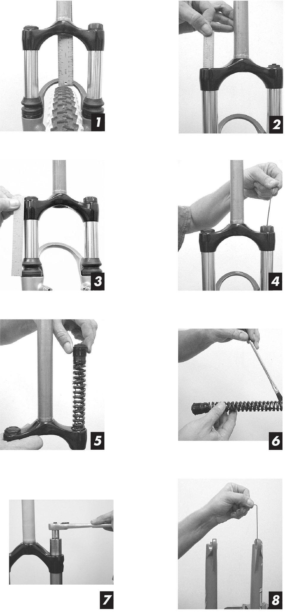
4 MANITOU SUSPENSION FORKS CONGRATULATIONS ON CHOOSING A 2003 MANITOU AXEL FORK. This Manitou AXEL fork is fully assembled and ready to be installed onto your bicycle. It comes equipped with a 1 1/8-inch threadless steerer tube, RA casting and is available with a V-brake-style hangerless arch. AXEL forks are also available in a disc brake only version. A handlebar-mounted reflector must be used for on-road use, which is not included with your fork MANITOU AXEL FORK LINE AXEL COMP...80 OR 100 MM TRAVEL* / COIL SPRINGS / FLUID FLOW DAMPING / SINGLE CROWN / RA CASTING AXEL ELITE...80 OR 100 MM TRAVEL* / COIL SPRINGS / FLUID FLOW DAMPING / SINGLE CROWN / RA CASTING AXEL SUPER...80 OR 100 MM TRAVEL* / COIL SPRINGS / FLUID FLOW DAMPING (REBOUND ADJUST) / SINGLE CROWN / RA CASTING / ALUMINUM STEERER TUBE *Preset from the factory, but changeable. See the Convertible Travel section in the Dealer Service Addendum for details. You can also download this manual at BICYCLING IS A HAZARDOUS ACTIVITY THAT REQUIRES THAT THE RIDER STAY IN CONTROL OF HIS OR HER BICYCLE AT ALL TIMES. READING THIS MANUAL ENTIRELY, AND PROPERLY MAINTAINING YOUR BICYCLE AND SUSPENSION FORK, WILL REDUCE THE POSSIBILITY OF INJURY OR POSSIBLE DEATH. PRIOR TO RIDING YOUR BICYCLE, YOU SHOULD INSPECT YOUR SUSPENSION FORK TO ENSURE THAT NO DAMAGE HAS OCCURRED DURING THE COURSE OF RIDING. DO NOT RIDE YOUR BICYCLE IF THE FORK SHOWS ANY SIGNS OF BENDING, CRACKING, CREAKING, LEAKING, OR IF IT IS MISSING ANY OF THE ORIGINALLY SUPPLIED COMPONENTS. ANY FALL FROM YOUR BICYCLE CAN RESULT IN SERIOUS INJURY OR EVEN DEATH. FOLLOWING THESE INSTRUCTIONS CAN HELP YOU REDUCE THE RISK OF BEING INJURED. IF YOU ARE A MODERATE OR AGGRESSIVE OFF-ROAD RIDER, OR RIDE AT LEAST THREE TIMES A WEEK OVER ROUGH TERRAIN, ANSWER RECOMMENDS RETURNING YOUR SUSPENSION FORK EVERY 2 YEARS FOR A THOROUGH INSPECTION AND UPDATE. TAKE YOUR FORK TO A MANITOU AUTHORIZED DEALER WHO CAN ARRANGE FOR SHIPMENT TO ANSWER PRODUCTS, OR YOU MAY CALL ANSWER AT (661) TO HAVE YOUR FORK SHIPPED DIRECTLY. IMPORTANT: The AXEL fork is an off-road fork, and as such, does not come with proper reflectors for on road use. Have your dealer or mechanic install proper reflectors to meet the Consumer Product Safety Commission s (C.P.S.C.) Requirements for Bicycles if the fork is going to be used on public roads at any time. If you have questions regarding C.P.S.C. Standards, or would like to purchase a reflector bracket kit (Part # ), contact your dealer. CONSUMER SAFETY INFORMATION 1. Never remove or have the steerer tube or stanchions removed from the crown. The steerer tube and stanchions (inner legs) are press fit at the factory. Press fit inner legs have higher performance versus bolt-in inner legs, but can not be pressed out. Pressing them out will permanently damage the crown beyond repair and render it unsafe for any continued use. 2. Never attempt to thread a threadless steerer tube. Cutting threads will weaken the steerer tube and cause an unsafe condition. The only safe thing to do is to obtain the proper crown/steerer from your dealer, or contact Answer Customer Service at (661) Any other alteration or modification to your fork should be considered unsafe. Contact Answer Customer Service prior to modifying your fork in any way for safety information. 4. Do not use the AXEL fork if any parts are broken, bent, cracked, or you suspect may be damaged. Contact your dealer or Answer Warranty (661) if you have any questions concerning the integrity or condition of your fork. 5. Answer Products recommends that you inspect your fork before every ride for wear and damage. Inspect the crown, inner legs, outer legs dropout and brake arch areas for cracks or damage. WARRANTY INFORMATION Any Answer Products fork found by the factory to be defective in materials and/or workmanship within one year from the date of purchase (or two years in EU countries) will be repaired or replaced at the option of the manufacturer, free of charge, when received at the factory with proof of purchase, freight prepaid. This warranty does not cover breakage, bending, or damage that may result from crashes or falls. This warranty does not cover any fork that has been subject to misuse or whose serial number has been altered, defaced or removed. This warranty does not cover paint damage. Any modifications made by the user will render the warranty null and void. This warranty is expressly in lieu of all other warranties, and any implied are limited in duration to the same duration as the expressed warranty herein. Answer Products shall not be liable for any incidental or consequential damages. If for any reason warranty work is necessary, return the fork to the place of purchase. At that time, instructions for repair, return, or replacement shall be given. Customers in countries other than USA should contact their dealer or local distributor. INSTALLATION INSTRUCTIONS Ensure that the proper steerer tube has been delivered on your Manitou AXEL. The steerer tube may need to be cut to length to fit your bicycle head tube. If you are not familiar with this procedure, or do not have the proper tools to cut the steerer tube, it is recommended that you seek a dealer with a qualified bicycle mechanic to perform installation. THE STEERER TUBE AND STANCHIONS (INNER LEGS) ARE A ONE TIME PRECISION PRESS FIT AT THE FACTO- RY AND CAN NOT BE REMOVED FROM THE CROWN. REPLACEMENT OF THE ENTIRE CROWN/STEERER ASSEMBLY MUST BE DONE TO CHANGE STEERER TUBE LENGTHS OR DIAMETERS. REMOVING AND REPLACING THE STEERER TUBE OR STANCHIONS WILL RESULT IN AN UNSAFE CONDITION AND SHOULD NEVER BE DONE. BREAK-IN Your new fork is designed to break-in during your first few rides (about 20 hours total riding time). Prior to break-in, you may notice your fork binds slightly and feels notchy. Following the break-in period, your fork will feel much smoother and will react to bumps much better than when you first put it on your bike. After 20 hours, you may want to recheck your rebound and preload adjustments (when applicable) to fine tune the fork completely. Between services on your Manitou fork, all you must do is lubricate your fork as needed with Manitou Prep M (part number for the lube and for the injector gun) via the Microlube grease ports located on the back of the fork legs. FORK INSTALLATION 1. Remove the old fork from your bicycle. 2. Measure and cut the steerer tube to fit your bicycle head tube. You can use your old fork as a guide for cutting the steerer tube length. 3. Remove the headset crown race from the old fork and press onto the Manitou AXEL steerer tube until the race is seated over the crown. 4. Clean and grease the headset bearings and races. 5. Install the lower bearings (if applicable) on the fork crown race. 6. Insert the steerer tube into the head tube of the frame. 7. Install the upper bearings, stem spacers, and stem. 8. Install the stem cap and bolt. Tighten the bolt to headset manufacturer s specifications. 9. Install the handlebars to desired height and the torque stem pinch screws or stem clamping system to manufacturer s specifications. 10. Install the brakes and adjust per the manufacturer s instructions. 11. For all AXEL forks, adjust the front wheel quick release to clear the 0.334" (8.5 mm) thick secondary catch dropout. The quick release must be tightened after it is properly seated into the dropout counter bores to manufacturer s specifications. Ensure that there is adequate thread engagement (4 or more threads with the release adjusted to lock). NOTE: 2003 Manitou AXEL forks are equipped with a secondary catch dropout to retain the wheel in the fork in the event the quick release comes loose. WHEN INSTALLING THE WHEEL OR A NEW TIRE, CHECK TO MAKE SURE THE FORK ACHIEVES MINIMUM TIRE CLEARANCE. MEASURE FROM THE HIGHEST POINT ON THE TIRE TO THE BOT- TOM OF THE BRAKE ARCH. THIS MEASUREMENT SHOULD BE 10 MM. (FIGURE 1) IMPORTANT: The Manitou AXEL fork should not be used if any parts appear to be or are damaged. Contact your local dealer or Answer Products for replacement parts.

5 MAINTENANCE IMPORTANT: Use of fork boots is required to keep your Manitou AXEL fork performing well and the warranty in effect. Use of this fork without boots will shorten the life of the fork, decrease the time between maintenance intervals, reduce the performance and void the warranty. IMPORTANT: When lubricating the fork with grease through the grease ports, it is important to note that grease is being forced between the upper and lower bushings. If the area is overfilled, the grease may force the upper bushing and dust seal out. You should only insert grease to the level at which stiction (stickiness when you compress the fork) is no longer felt. IMPORTANT: Before every ride you should: 1. Ensure that quick release skewers are properly adjusted and tight. 2. Wipe the inner legs and clean and check entire fork for any obvious damage. 3. Check the headset for proper adjustment. 4. Ensure that the front brake cable is properly routed and check brake adjustment. CHECKING OIL LEVEL IMPORTANT: Setting the proper oil level in your Fluid Flow damped fork is critical. Fluid Flow damping is located in the right leg of your Manitou AXEL fork. Not enough oil will allow foaming and reduce the performance. Too much oil will restrict travel and may cause damage to the system and create an unsafe riding condition. Finish reading this entire section prior to altering the oil level. To check the oil level on the Manitou AXEL, remove the compression assembly located in the top of the right leg (as you are looking at the fork from the rider s position). Leave the left side spring stack in place to keep the fork fully extended. Use a tape measure or dip stick to measure from the top of the fork crown down to where the oil sits (Figure 2). The oil level for the Manitou AXEL should be per following table. Fork Model Oil Level Manitou AXEL mm ( ) NOTE: Use SAE 5WT fork oil suspension fluid only. If you have any questions regarding your 2003 Manitou AXEL suspension fork, contact the Answer Products Customer Service Department at (661) You can also log on to and download this manual or see detailed instructions on how to service your suspension fork. Thank you again for choosing a 2003 Manitou AXEL suspension fork. AXEL DEALER SERVICE ADDENDUM This section is designed to help you tune and maintain your Manitou suspension fork. MEASURING SAG To measure sag, you ll need a tape measure, a pencil, a piece of paper and a helper. 1. Measure the distance from the front axle s centerline to the bottom of the upper crown when no one s sitting on the bike and write this distance down. (Remember the exact locations of the two points because you ll need to use them later.) 2. Have the rider sit on the bike and measure the distance between the same two points as in step one. It s important to be in the normal riding position (weight centered) with the rider s feet on the pedals. 3. Subtract the second measurement from the first. The resulting measurement is the static sag or ride height. SAG MEASUREMENT Fork Travel Sag 80 mm mm 100 mm mm TRAVEL MEASUREMENT To determine which travel your AXEL fork is in, simply measure the distance from the top of the seal area on the lowers (or the bottom of the fork boot) to the bottom of the crown (Figure 3). Fork Travel Seal to Crown Measurement 80 mm Around 4.3 inches or 109 mm 100 mm Around 5.2 inches or 130 mm RECOMMENDED SPRINGS AXEL Rider Weight Recommended Spring Kit lbs. Soft ride kit (Part # ) Standard Set-up lbs. Medium ride kit (Part # ) 170 plus lbs. Firm ride kit (Part # ) CHANGING SPRINGS AND/OR MCU S Once you have checked sag, you can either preload the spring via the cap on top of the left hand leg, or even better, make spring changes to accommodate for your riding style and weight. 1. Start by removing the preload adjuster by unscrewing the 2 mm hex bolt on the adjuster knob. A 20 mm socket will be necessary with the AXEL. Remember: The springs are housed only in the left leg on 2003 Manitou suspension forks. (Figure 4) 2. With the adjuster assembly removed, the spring stack is now accessible. (Figure 5) 3. Select the appropriate coil spring for your weight and riding style (refer to the above spring chart for recommended rates). 4. Apply a liberal amount of grease to the outside surface of the new coil spring (Figure 6). We recommend any thick grease (not light greases like Prep M). Install the new spring stack. 5. Reinstall the preload adjuster knob and adjuster assembly, taking care not to cross-thread the adjuster assembly. It should be snug tightened with a wrench. (Figure 7) CONVERTIBLE TRAVEL 1. Changing the travel from 80 to 100 millimeters or vice-versa requires the removal of the lower legs. 2. Remove the rebound adjuster knob with a 2 mm hex wrench (AXEL Elite and Super models only). (Figure 8) 3. Next unthread (clockwise to loosen) the 8 mm and 4 mm bolts on the bottom of the fork and pull the lowers free from the uppers. Unscrew the cap on the bottom of the right leg (as seen from the rider s position). This will expose the clip that is used to adjust the travel. (Figure 9) 4. Remove the clip and insert it into the upper position (above the rod flange) for 100 millimeters of travel or the lower position (below the rod flange) for 80 millimeters of travel. (Figure 10) 5. Reassemble fork. MAINTENANCE AND SERVICE INTRODUCTION When servicing the fork, take the time to inspect all parts for excessive wear or damage. There are basically four aspects of a fork that will require attention: the stanchions (inner legs), the bushings in the outer legs, the spring stack and the damping fluid. Inspecting any of these parts requires disassembly of the fork. Pay close attention to the bushings, which can be damaged by contamination in severe conditions. Replace any worn or damaged parts that are discovered. CHANGING THE OIL IN YOUR FORK Changing the oil in your damped fork is very easy to do. All of the damping systems, FFD, TPC and TPC Plus, house the oil in the right leg. 1. Remove the cap from the top of the right fork leg (1 1 /16" socket). (Figure 11) 2. Rock the compression damping assembly back and forth slightly as you pull up on it to remove it.

6 3. Pour the old oil out of the fork. (Figure 12) 4. Stroke the fork up and down to remove the oil that settles beneath the rebound piston. Pour this oil out as well. (Figure 13) 5. Add oil to the level shown in the Checking Oil Level section of this manual. (Figure 14) Cover the leg opening and stroke the fork up and down a few times before the final measurement is taken to ensure that oil has flowed beneath the rebound piston again. FORK DISASSEMBLY Disassembly of your AXEL fork is necessary to provide the proper service of your fork. To do this: 1. Remove the adjustment knob on the bottom of your fork with a 2 mm Allen wrench. 2. Remove the bolts from the bottom of the fork leg with 4 and 8 mm wrenches and set aside. (Figure 15) 3. You can now pull apart the fork, removing the casting from crown/steerer assembly. (Figure 16) 4. Wipe clean the inside of the fork casting, stanchion tubes, fork boots, and crown. At the same time you do this, do a complete inspection on the fork. (Figure 17) MICROLUBE All you need is a Microlube lubricant gun (part # ) and Manitou s Prep M suspension fork lubricant (part # ). Brush any dirt from the grease ports and inset the grease gun into the small fitting located at the back of the fork and squeeze a few times. Continue injecting grease and push the fork up and down until stiction is eliminated. SERVICE SCHEDULE Suggested Service for Manitou forks NORMAL CONDITIONS Short/Infrequent Rides Lube fork as needed with Prep M lubricant via Microlube ports. Disassemble, clean and lubricate fork every 4-5 months. Service FFD by changing damping fluid every year. NORMAL CONDITIONS Long/Frequent Rides Lube fork as needed with Prep M lubricant via Microlube ports. Disassemble, clean and lubricate fork every weeks. Service FFD by changing damping fluid every 6 months. SEVERE CONDITIONS (MUD, RAIN, SNOW, EXTREME DUST) Short/Infrequent Rides Lube fork as needed with Prep M lubricant via Microlube ports. Disassemble, clean and lubricate fork every 6-8 weeks. Service FFD by changing damping fluid every year. SEVERE CONDITIONS (MUD, RAIN, SNOW, EXTREME DUST) Long/Frequent Rides Lube fork as needed with Prep M lubricant via Microlube ports Disassemble, clean and lubricate fork every 4-6 weeks. Service FFD by changing damping fluid every 6 months.

99 SX SERVICE MANUAL
 99 SX SERVICE MANUAL P/N 85-3666 MANITOU ANSWER PRODUCTS, INC 28209 AVENUE STANFORD, VALENCIA, CA 91355 (805) 257-4411 www.answerproducts.com TABLE OF CONTENTS Consumer Safety & Warranty Information. 1
2004 SERVICE MANUAL Axel Super Axel Elite Axel Comp
 2004 SERVICE MANUAL Axel Super Axel Elite Axel Comp 28209 Avenue Stanford, Valencia, California 91355 661 257-4411 fax 661 294-4179 www.answerproducts.com Table of Contents Description Page Introduction
MANITOU SWINGER REAR SHOCK OWNER S MANUAL P/N 042105
 MANITOU SWINGER REAR SHOCK OWNER S MANUAL P/N 042105 MANITOU SWINGER REAR SHOCK This Manitou Swinger SPV (Stable Platform Valve) shock is fully assembled and ready to be installed onto your bicycle. Special
VT SERIES. Owners Manual VARIABLE TRAVEL MOUNTAIN BIKE
 VT SERIES Owners Manual VARIABLE TRAVEL MOUNTAIN BIKE Multi purpose, Enduro, Trail ride, Light Freeride mountain bike Single pivot, linkage operated rear shock rear suspension Manitou Swinger SPV Air rear
For exploded diagram and part number information, refer to the Spare Parts Catalog available on our website at www.rockshox.com.
 For exploded diagram and part number information, refer to the Spare Parts Catalog available on our website at www.rockshox.com. Information contained in this publication is subject to change at anytime
2004 SERVICE MANUAL Skareb Platinum Skareb Super Skareb Elite Skareb Comp
 2004 SERVICE MANUAL Skareb Platinum Skareb Super Skareb Elite Skareb Comp 28209 Avenue Stanford, Valencia, California 91355 661 257-4411 fax 661 294-4179 www.answerproducts.com Table of Contents Description
2006 JUDY SERVICE GUIDE
 2006 JUDY SERVICE GUIDE For exploded diagram and part number information, refer to the Spare Parts Catalog available on our website at www.rockshox.com. Information contained in this publication is subject
DUAL CROWN. 2011 Technical Manual
 DUAL CROWN 2011 Technical Manual TABLE OF CONTENTS GETTING STARTED...3 PARTS...3 TOOLS...3 RECORD YOUR SETTINGS...4 OIL VOLUME CHART...5 TORQUE CHART...5 SERVICE INTERVALS...5 ANATOMY...6 FORK REMOVAL...8
CONGRATULATIONS! TABLE OF CONTENTS. 1 Safety Warnings 2 About Your Wheels 3 Setting Up Your Wheels 7 Care and Cleaning 8 Warranty
 WHEEL MANUAL CONGRATULATIONS! Congratulations on your purchase of Oval Concepts Wheels. Developed to perform at a high level, it is important that you follow the operation and maintenance instructions
Owner s Manual Read and keep this manual. Patents World Wide
 Owner s Manual Read and keep this manual. Patents World Wide S & S Industries, Inc., Sarasota, FL, USA www.trail-gator.com Copyright 2008 All Rights Reserved The following manual is provided to assist
For exploded diagram and part number information, refer to the Spare Parts Catalog available on our website at www.rockshox.com.
 For exploded diagram and part number information, refer to the Spare Parts Catalog available on our website at www.rockshox.com. 2 0 0 5 D U K E A I R X C / S L / R A C E S E R V I C E G U I D E Information
XC28 XC30. Service Manual. GEN.0000000004936 Rev A 2015 SRAM, LLC
 XC28 XC30 Service Manual GEN.0000000004936 Rev A 2015 SRAM, LLC SRAM LLC WARRANTY EXTENT OF LIMITED WARRANTY Except as otherwise set forth herein, SRAM warrants its products to be free from defects in
2003-2004 PILOT SL & XC SERVICE GUIDE
 For exploded diagram and part number information, refer to the Spare Parts Catalog available on our website at www.rockshox.com. 2003-2004 PILOT SL & XC SERVICE GUIDE Contact your local distributor or
Ceriani Replica GP35R forks. Technical description
 Ceriani Replica GP35R forks Technical description This is an advanced racing replica of the GP35 forks. The legs are made from 6061 aluminium, mounted with CNC machined fittings, the stanchions are from
Table of Contents WARNING SYMBOLS AND DEFINITIONS
 Table of Contents SAFETY INSTALLATION OPERATION MAINTENANCE Safety... 2 Specifications... 4 Installation... 5 Operation... 8 WARNING SYMBOLS AND DEFINITIONS Maintenance... 9 Parts List and Assembly Diagram...
TUNING GUIDE. ridefox.com
 TUNING GUIDE ridefox.com OUR LIGHTEST 34 FORK EVER: REDESIGNED FOR 27.5 AND 29 WHEEL SIZES The model year 2016 34 offers many of the benefits from the 36; rigidity and improved traction for aggressive
INSTRUCTIONS. FLHR/C/S (Road King) FRONT END LOWERING KIT 1WARNING -J03242 REV. 10-19-04. General. Removal (Left and Right Forks) Kit Number 54614-05
 FRONT END LOWERING KIT 1WARNING -J03242 REV. 10-19-04. General. Removal (Left and Right Forks) Kit Number 54614-05") INSTRUCTIONS -J04 REV. 0-9-04 General FLHR/C/S (Road King) FRONT END LOWERING KIT This kit is designed for installation on 00 and later FLHR/C/S Model Motorcycles. Road King models use the conventional
INSTRUCTIONS -J04 REV. 0-9-04 General FLHR/C/S (Road King) FRONT END LOWERING KIT This kit is designed for installation on 00 and later FLHR/C/S Model Motorcycles. Road King models use the conventional
Hydraulic Disc Brake, Installation, Maintenance, and Service Manual
 Hydraulic Disc Brake, Installation, Maintenance, and Service Manual HFX-Mag HFX-9 45-14550DWeb 02/06 copyright 2006 Hayes Bicycle Group, LLC Introduction to this Manual This manual is intended to provide
2011 - PRESENT DOMAIN DUAL CROWN. Service Manual
 2011 - PRESENT DOMAIN DUAL CROWN Service Manual SRAM LLC WARRANTY EXTENT OF LIMITED WARRANTY Except as otherwise set forth herein, SRAM warrants its products to be free from defects in materials or workmanship
STEERING HANDLEBAR/FRONT WHEEL/ FRONT SHOCK ABSORBER
 14 14 STEERING HANDLEBAR/FRONT WHEEL/ SCHEMATIC DRAWING ------------------------------------------------- 14-1 SERVICE INFORMATION------------------------------------------------ 14-2 TROUBLESHOOTING-----------------------------------------------------
2014 Sektor/Recon/XC32 Solo Air Service Manual
 2014 Sektor/Recon/XC32 Solo Air Service Manual SRAM LLC WARRANTY EXTENT OF LIMITED WARRANTY Except as otherwise set forth herein, SRAM warrants its products to be free from defects in materials or workmanship
2005-2006 PIKE REBA REVELATION DUAL AIR SERVICE GUIDE
 For exploded diagram and part number information, refer to the Spare Parts Catalog available on our website at www.rockshox.com. Information contained in this publication is subject to change at anytime
PALLET JACK - 2.5 TON
 PALLET JACK - 2.5 TON 39939 SET UP AND OPERATING INSTRUCTIONS Visit our website at: http://www.harborfreight.com Read this material before using this product. Failure to do so can result in serious injury.
2013 Sektor/Recon/XC32 Solo Air Service Manual
 2013 Sektor/Recon/XC32 Solo Air Service Manual GEN.0000000004207 Rev A Copyright 2012 SRAM, LLC SRAM LLC WARRANTY Extent of Limited Warranty Except as otherwise set forth herein, SRAM warrants its products
BOXXER RC. Service Manual
 2015 BOXXER RC Service Manual SRAM LLC WARRANTY EXTENT OF LIMITED WARRANTY Except as otherwise set forth herein, SRAM warrants its products to be free from defects in materials or workmanship for a period
PROPER BIKE USE. ATTENTION: Aforementioned checks should be done by the seller during purchase. It s buyers responsibility to control it.
 USER MANUAL INTENDED USE This bike has been designed for dirt/street riding. These disciplines concentrate on performing tricks after jumping from a previously prepared jump. Landing takes place on an
Instructions and precautions. Fork Height. Visit our website at: http://www.harborfreight.com
 Pallet Jack Item 68760 / 68761 Instructions and precautions Specifications Capacity Control Lever Fork Height Fork Length Fork Width Maximum Minimum Width over Forks Steering Wheel Dia. 2-1/2 Ton (5,000
Giant NRS. Model Year. Owners Manual. July 2003.
 Giant NRS Model Year 2004 Owners Manual July 2003. Contents. 1. Introduction.... 2 2. Sizing.... 3 3. Exploded view... 4 4. Rear suspension... 5 4-1 NRS rear suspension system.... 5 4-2 Bikes equipped
HYDRAULIC TABLE CART
 Owner s Manual & Safety Instructions Save This Manual Keep this manual for the safety warnings and precautions, assembly, operating, inspection, maintenance and cleaning procedures. Write the product s
TABLE OF CONTENTS. Section 1 - Assembling your new pit bike.
 Orion Pit Bike Sales Owners Manual (All information and content is the property of Orion Pit Bike Sales. Any attempt to copy or resell is a direct violation of our copyright. All violators will be prosecuted)
Cane Creek Double Barrel Instructions
 Cane Creek Double Barrel Instructions Congratulations on your purchase of the Cane Creek Double Barrel (CCDB) rear shock. Developed in partnership with Öhlins Racing, the Double Barrel brings revolutionary
Street-Lynx. Reilly MotorSports, Inc. Installation Manual
 Street-Lynx By Reilly MotorSports, Inc. Installation Manual 1 1- Begin by removing your original rear suspension disconnect your brake lines, E-brake cables, and remove the driveshaft. To prevent fire
2006 HEADSHOK Service Video #1
 LEFTY SPEED DLR DAMPING CARTRIDGE This document explains how to properly remove, disassemble, inspect, reassemble and reinstall the Lefty Speed DLR2 damping cartridge. It is a document to be used in conjunction
Installation manual. 1.75 front leveling kit. 2011 Dodge Durango 2011-2014 Jeep Grand Cherokee. Part # 42006. Part # 42006
 Installation manual 1.75 front leveling kit 2011 Dodge Durango 2011-2014 Jeep Grand Cherokee Part # 42006 sj02282011rev.01 Part # 42006 2011-2014 Dodge Durango 2011 Jeep Grand Cherokee 1.75 front leveling
Service Manual Rol-Lift
 R 2000 Service Manual Rol-Lift Series: T and E Developed by Generic Parts Service This manual is intended for basic service and maintenance of the Rol-Lift pallet jack. The pallet jacks you are servicing
Front brakes (FN- 3), servicing
, servicing") j a t Front brakes (FN- 3), servicing 46-1 Front brakes, servicing Note: Install complete repair kit. After replacing brake pads and before moving vehicle, depress brake pedal several times firmly to properly
j a t Front brakes (FN- 3), servicing 46-1 Front brakes, servicing Note: Install complete repair kit. After replacing brake pads and before moving vehicle, depress brake pedal several times firmly to properly
SCION tc 2005-2008 COIL OVER SUSPENSION Preparation
 SCION tc 2005-2008 COIL OVER SUSPENSION Preparation Part Number: PTR11-21070 NOTE: Part number of this accessory may not be the same as the part number shown. Kit Contents: Item # Quantity Reqd. Description
ROTOR LOADER OWNER S MANUAL
 ROTOR LOADER OWNER S MANUAL ROTOR LOADER OWNER S MANUAL WARNING IMPORTANT SAFETY INSTRUCTIONS AND GUIDELINES. Misuse of paintball equipment may cause serious injury or death. QUICK SET-UP GUIDE BATTERY
INSTALLATION INSTRUCTIONS. 6108 Air Spring Kit 2011+ Ford F250 Single Wheel 4WD 2011+ Ford F350 Dually 4WD (2011 F350 Single Wheel 4WD use p/n 6113)
") INSTALLATION INSTRUCTIONS 6108 Air Spring Kit 2011+ Ford F250 Single Wheel 4WD 2011+ Ford F350 Dually 4WD (2011 F350 Single Wheel 4WD use p/n 6113) Thank you for purchasing a quality Hellwig Product. PLEASE
INSTALLATION INSTRUCTIONS 6108 Air Spring Kit 2011+ Ford F250 Single Wheel 4WD 2011+ Ford F350 Dually 4WD (2011 F350 Single Wheel 4WD use p/n 6113) Thank you for purchasing a quality Hellwig Product. PLEASE
IMPORTANT DOCUMENTATION DO NOT DISCARD!
 PART NO.: 6441-263C SERIES GRT 3 JAW PARALLEL GRIPPERS INFORMATION SHEET IMPORTANT DOCUMENTATION DO NOT DISCARD! Use this information sheet to assist with gripper installation and setup. File with maintenance
HYDRAULIC LIFT TABLE CART 2200-LB.
 HYDRAULIC LIFT TABLE CART 2200-LB. OWNER S MANUAL WARNING: Read carefully and understand all MACHINE ADJUSTMENT AND OPERATION INSTRUCTIONS before operating. Failure to follow the safety rules and other
PEDAL CAR - GO CART ASSEMBLY & OPERATING INSTRUCTIONS
 PEDAL CAR - GO CART 42822 ASSEMBLY & OPERATING INSTRUCTIONS 3491 Mission Oaks Blvd., Camarillo, CA 93011 Visit our Web site at: http://www.harborfreight.com Copyright 2000 by Harbor Freight Tools. All
Strut Spring Compressor
 Strut Spring Compressor Item 43753 Read this material before using this product. Failure to do so can result in serious injury. SAVE THIS MANUAL. When unpacking, make sure that the product is intact and
WARNING! WARNING! ENGLISH 18 ENGLISH
 SKELETON RAKES Carefully read, follow and understand the instructions given in this manual. It is an essential part of the product, and you should keep it in a safe place for future reference. MECHANIC
2003-2004 SID REAR SERVICE GUIDE
 2003-2004 SID REAR SERVICE GUIDE For exploded diagram and part number information, refer to the Spare Parts Catalog available on our website at www.rockshox.com. Contact your local distributor or visit
Rear wheel brakes, servicing. Стр. 1 из 45. Note:
 Volkswagen Touareg - Rear wheel brakes, servicing Стр. 1 из 45 46-2 Rear wheel brakes, servicing Rear brakes, FN 44 brake caliper, servicing Note: After replacing brake pads, depress brake pedal firmly
2003-2004 SID SERVICE GUIDE
 2003-2004 SID SERVICE GUIDE For exploded diagram and part number information, refer to the Spare Parts Catalog available on our website at www.rockshox.com. Contact your local distributor or visit the
DiscPlus DX195 and DX225 Air Disc Brakes
 Revised 11-04 Technical Bulletin Revised 1 Technical 11-04 Bulletin DiscPlus DX195 and DX225 Air Disc Brakes Inspection, Installation and Diagnostics Air Disc Brake Inspection Intervals and Procedures
SE-100-1, SE-200-1, SE-500-1, and SE-1000-1 AIR CHAMP PRODUCTS. User Manual SE BRAKE MODELS: (i) MTY (81) 83 54 10 18 ventas@industrialmagza.
 MTY (81) 83 54 10 18 ventas@industrialmagza.") AIR CHAMP PRODUCTS User Manual SE BRAKE MODELS: SE-00-, SE-200-, SE-500-, and SE-000- (i) FORM NO. L-20084-E-040 In accordance with Nexen s established policy of constant product improvement, the specifications
AIR CHAMP PRODUCTS User Manual SE BRAKE MODELS: SE-00-, SE-200-, SE-500-, and SE-000- (i) FORM NO. L-20084-E-040 In accordance with Nexen s established policy of constant product improvement, the specifications
Triple Threat 3-in-1 Game Table 3 IN 1 GAME TABLE
 NG0M Triple Threat 3-in- Game Table 3 IN GAME TABLE Thank 3 in Y Game Table Thank you for your purchase of our product. We work around the clock and around the globe to ensure that our products maintain
2007 Fork Service Manual. Rev 8/28/06
 2007 Fork Service Manual Rev 8/28/06 1 Table of ontents Description Page Introduction 3 Front Suspension Terminology 4 Section 1 - Disassembly/ssembly Instructions Damping Systems -B Kits Section 2 rown
Overview PARTS LIST. B. Lever mounting base C. Flush handle assembly D. Grey/Blue float stop E. Grey float (Full Flush) F. Flush valve washer
 F. Flush valve washer") Overview READ ENTIRE INSTRUCTIONS BEFORE STARTING INSTALLATION PARTS LIST A. Flush valve B. Lever mounting base C. Flush handle assembly D. Grey/Blue float stop E. Grey float (Full Flush) F. Flush valve
Overview READ ENTIRE INSTRUCTIONS BEFORE STARTING INSTALLATION PARTS LIST A. Flush valve B. Lever mounting base C. Flush handle assembly D. Grey/Blue float stop E. Grey float (Full Flush) F. Flush valve
WARNING TO END USER, INSTALLER AND SELLER OF THIS PART!
 WARNING TO END USER, INSTALLER AND SELLER OF THIS PART! By installing this part you are accepting full responsibility and liability for proper wheel and tire fitment after installation. It is the installer
FJ2. 2 Ton Trolley Floor Jack Assembly & Operating Instructions
 FJ2 2 Ton Trolley Floor Jack Assembly & Operating Instructions READ ALL INSTRUCTIONS AND WARNINGS BEFORE USING THIS PRODUCT. This manual provides important information on proper operation & maintenance.
Check air pressure E E E E E E Remove lower legs, clean/inspect bushings and change oil bath
 Service Intervals Service Intervals Judy Dart Pilot Duke Psylo Tora Recon Reba Clean dirt and debris from upper tubes E E E E E E E E Inspect upper tubes for scratches E E E E E E E E Lubricate dust seals/upper
DM-PD0001-00. (English) Dealer's Manual PD-MX80
 Dealer's Manual PD-MX80") (English) DM-PD0001-00 PD-MX80 Dealer's Manual IMPORTANT NOTICE This dealer s manual is intended primarily for use by professional bicycle mechanics. Users who are not professionally trained for bicycle
(English) DM-PD0001-00 PD-MX80 Dealer's Manual IMPORTANT NOTICE This dealer s manual is intended primarily for use by professional bicycle mechanics. Users who are not professionally trained for bicycle
Owner s Manual & Safety Instructions
 Owner s Manual & Safety Instructions Save This Manual Keep this manual for the safety warnings and precautions, assembly, operating, inspection, maintenance and cleaning procedures. Write the product s
Table of Contents. Overview 1. Pump Disassembly 2. Control Disassembly / Reassembly 7. Pump Reassembly 13. Adjustment Procedures DR Control 19
 Table of Contents Overview 1 Pump Disassembly 2 Control Disassembly / Reassembly 7 Pump Reassembly 13 Adjustment Procedures DR Control 19 Adjustment Procedures DRG Control 20 Adjustment Procedures DFR
White Industries Rear Hub Instructions
 White Industries Rear Hub Instructions Tool required: 2mm allen/hex wrench, 19mm socket, 20mm socket, and mallet. 1. Loosen the set screws located in the adjusting collar by using a 2mm allen wrench inserted
SELF-STEERING AXLE TABLE OF CONTENTS
 SELF-STEERING AXLE TABLE OF CONTENTS Section 1 - Introduction Section 2 - Pre-Installation Check List Section 3 - Ride Height Adjustments Section 4 - Suspension Mount Section 5 - Axle Mount Section 6 -
Johnny G Spinner Pro and Johnny G Spinner Elite Owner s Manual
 Johnny G Spinner Pro and Johnny G Spinner Elite Owner s Manual www.startrac.com Table of Contents: 1) Introduction 2) Fitness Safeguards 3) Spinner Pro and Elite Features 4) Assembly Instructions / Parts
2011 Technical Manual
 2011 Technical Manual SRAM LLC WARRANTY SRAM warrants its products to be free from defects in materials or workmanship for a period of two years after original purchase. This warranty only applies to the
Your New Frog Bike. Congratulations on purchasing a new bike and thank you for choosing Frog!
 Your New Frog Bike Congratulations on purchasing a new bike and thank you for choosing Frog! We know that you must be raring to go but before you do there s a few little things still to do to get you up
INSTALLATION INSTRUCTIONS COMPETITION SERIES COILOVER SUSPENSION SYSTEM 03+ Scion xb
 INSTALLATION INSTRUCTIONS COMPETITION SERIES COILOVER SUSPENSION SYSTEM 03+ Scion xb NOTE: Progress Technology products should only be installed by a qualified licensed mechanic experienced in the installation
GUIDE RSC. Service Manual
 2015 GUIDE RSC Service Manual SRAM LLC WARRANTY EXTENT OF LIMITED WARRANTY Except as otherwise set forth herein, SRAM warrants its products to be free from defects in materials or workmanship for a period
Hydraulic Transmission Jacks Operating Instructions & Parts Manual
 Blackhawk Automotive is a Licensed Trade Mark Made by SFA Companies, Kansas City, MO Hydraulic Transmission Jacks Operating Instructions & Parts Manual Model BH7011 BH7210 Capacity 1/2 Ton 1 Ton SFA Companies
ARVINMERITOR UNITIZED FRONT WHEEL HUB INSPECTION AND MAINTENANCE
 SERVICE BULLETIN (Also applies to Mack Trucks Australia) NUMBER: SB-423-002 DATE: 8/23/02 MODEL: All with FF981 Front Axle ARVINMERITOR UNITIZED FRONT WHEEL HUB INSPECTION AND MAINTENANCE The ArvinMeritor
Front axle components, overview
 just a test. Front axle components, overview 40-1 General Information Load bearing components and parts of the suspension must not be welded or straightened. Vehicles without drive axle must not be moved,
Installation Instructions and Service Manual
 Installation Instructions and Service Manual Model 85, 85-3/4 & 85E Actuator* for Trailer Brakes 8,500 lbs. Capacity for use with -5/16 Hitch Balls Drum Brake Ready - Part #4736 Disc Brake Ready - Part
JK 2.5 Spring Lift Part # 1251000-1251002 # 1351000-1351002 # 1352000-1352002
 TeraFlex, Inc. 5241 South Commerce Dr. Murray, Utah 84107 Phone/801.288.2585 Fax/801.713.2313 www.teraflex.biz Rev. 2 December 2010 TT PRODUCT INSTALLATION GUIDE JK 2.5 Spring Lift Part # 1251000-1251002
DYNA RIDER FOOTBOARD KIT
 -J0 REV. 0-0-0 DYNA RIDER FOOTBOARD KIT GENERAL Kit Number 000 Models For model fitment information, see the P&A Retail Catalog or the Parts and Accessories section of www.harley-davidson.com (English
Bicycoo BMX Instruction Manual 0014X Series
 Bicycoo BMX Instruction Manual 0014X Series Joovy 2919 Canton Street Dallas, TX 75226 (877) 456-5049 Fax: (214) 761-1774 Email: [email protected] Web Site: www.joovy.com ! WARNINGS Please read
Installation Instructions
 85-3976 rev. 05 08-13 Installation Instructions Thank you for purchasing this antisway bar kit. Please read through these instructions before installation. Rear Anti-Sway Bar Kit for Dodge Ram Pick-Up
ASSEMBLY DIAGRAM AND ASSEMBLY REFERENCE ULTIMA OLD SCHOOL 2 EVO & TC BELT DRIVE UNITS
 ASSEMBLY DIAGRAM AND ASSEMBLY REFERENCE ULTIMA OLD SCHOOL 2 EVO & TC BELT DRIVE UNITS BELT DRIVE ASSEMBLIES Part# 58-850 2 Old School Belt Drive Assembly - Polished Part# 58-851 2 Old School Belt Drive
Char-Lynn Hydraulic Motor. Repair Information. 10 000 Series. October, 1997
 Char-Lynn Hydraulic Motor October, 1997 Repair Information Geroler Motor Two Speed 001 27 Retainer inside bore of valve plate bearingless motors only 4 15 16 3 6 35 Parts Drawing 25 2 2 1 19 17 36 40 47
4.5 LIFT BOX KIT 2009 2013 DODGE RAM 2500 & 3500 4WD DIESEL ENGINE ONLY FTS23031
 4.5 LIFT BOX KIT 2009 2013 DODGE RAM 2500 & 3500 4WD DIESEL ENGINE ONLY FTS23031 Fabtech Motorsports 4331 Eucalyptus Ave. Chino, CA 91710 Tech Line 909-597-7800 Fax 909-597-7185 Web www.fabtechmotorsports.com
H EAD TUBE BASICS. Figure 1 - Head tube, front fork and hardware
 H EAD TUBE BASICS Figure 1 - Head tube, front fork and hardware This tutorial will cover some of the basics you need to know when pulling apart the steering system of a bicycle for repair or use on one
Unit: mm(in) Item Standard value Service limit Axle shaft run out - 0.2(0.008)
 Item Standard value Service limit Axle shaft run out - 0.2(0.008)") Rear Wheel/Brake/Suspension 13. Rear Wheel/Brake/Suspension Service Information 13-1 Troubleshooting 13-2 Rear Wheel 13-3 Rear Cushion 13-4 Rear Swing Arm 13-7 Service Information General Safety If the
Rear Wheel/Brake/Suspension 13. Rear Wheel/Brake/Suspension Service Information 13-1 Troubleshooting 13-2 Rear Wheel 13-3 Rear Cushion 13-4 Rear Swing Arm 13-7 Service Information General Safety If the
MP-4V Heavy Duty Riveter / 39048
 MP-4V Heavy Duty Riveter / 39048 This newly designed heavy-duty air/hydraulic riveter is ergonomically designed with the professional in mind. The light weight 3.7 lbs. well balanced MP-4V includes a Vacuum
jbs nfb INSTALLATION INSTRUCTIONS AND OWNERS MANUAL Mechanical Steering for Inboard, Outboard, and Sterndrive Powered Vessels
 MEMBER INSTALLATION INSTRUCTIONS AND OWNERS MANUAL Part # IS-SH5094, Rev 3, 04/204 www.seastarsolutions.com SH5294 DUAL SH5094 SINGLE jbs nfb Mechanical Steering for Inboard, Outboard, and Sterndrive Powered
MKV Golf GTI Rear Brake Service - Replace Pads and Rotors
 Page 1 Installation Procedures MKV Golf GTI Rear Brake Service - This tutorial is provided as a courtesy by ECS Tuning. Proper service and repair procedures are vital to the safe, reliable operation of
13. REAR WHEEL/BRAKE/SUSPENSION
 13. REAR WHEEL/BRAKE/SUSPENSION 13 3.5~4.5kg-m 8.0~10.0kg-m 0.8~1.2kg-m 3.0~4.0kg-m 2.4~3.0kg-m 3.5~4.5kg-m 6.0~8.0kg-m 13-0 13. REAR WHEEL/BRAKE/SUSPENSION 13 REAR WHEEL/BRAKE/SUSPENSION SERVICE INFORMATION...
Installation manual. 3 suspension system. 2009-2013 Ford F150. Part # 23000. Part # 23000. Important customer information: 2009-2013 Ford F150
 Installation manual 3 suspension system 2009-2013 Ford F150 Part # 23000 sj12112012rev.03 Part # 23000 2009-2013 Ford F150 3 suspension system Part # Description Qty. 23000-01 Driver side upper control
ELECTRIC BICYCLE USER MANUAL
 ELECTRIC BICYCLE USER MANUAL 1 Main Technical Parameters and Specification Weight: 23 kg Wheel size: 20 Maximum speed: 25 km/h E BIKE URBAN Range: Up to 45km (with pedal assist) Type: lithium Voltage:
WWW.SHAUNWHITESUPPLYCO.COM
 Bike Owner s Manual CONGRATULATIONS ON THE PURCHASE OF YOUR NEW BIKE! OUR SERVICE DEPARTMENT IS DEDICATED TO MAKING SURE THAT YOU GET THE MOST ENJOYMENT POSSIBLE FROM OUR PRODUCTS. For questions regarding
INSTALLATION INSTRUCTIONS. 6111 Air Spring Kit 2011+ Ford F250/F-350 Single Wheel 2WD 2011+ Ford F350 Dually 2WD IMPORTANT NOTES
 INSTALLATION INSTRUCTIONS 6111 Air Spring Kit 2011+ Ford F250/F-350 Single Wheel 2WD 2011+ Ford F350 Dually 2WD Thank you for purchasing a quality Hellwig Product. PLEASE READ THIS INSTRUCTION SHEET COMPLETELY
16 April 2012 1032011-F 1994-2002 Dodge Adjustable Track bar with Relocation Bracket 1
 16 April 2012 1032011-F 1994-2002 Dodge Adjustable Track bar with Relocation Bracket 1 BD Adjustable Track Bar w/bracket Dodge 2500-3500 4WD Models 1994-2002 Dodge 1500 4WD Model 1994-2001 P/N# 1032011-F
OWNER S MANUAL Table Tennis Table Patent Pending
 OWNER S MANUAL Table Tennis Table Patent Pending Be sure to write your model number and serial number here for future reference. You can find these numbers printed on the bottom of the table. MODEL # T8179
SLACK PERFORMANCE KARTS
 SLACK PERFORMANCE KARTS SET UP GUIDE Thank you for purchasing a 2013 Slack Axiom Chassis. Performance Mfg. strives to provide you with the very best chassis and components on the market today. Your satisfaction
AXLE SHAFTS - FRONT. 1993 Toyota Celica DESCRIPTION REMOVAL, DISASSEMBLY, REASSEMBLY & INSTALLATION. 1993 DRIVE AXLES Toyota FWD Axle Shafts
 AXLE SHAFTS - FRONT 1993 Toyota Celica 1993 DRIVE AXLES Toyota FWD Axle Shafts Toyota; Celica DESCRIPTION Axle shafts transfer power from transaxle to driving wheels. All axle shafts consist of a shaft
2011 Technical Manual
 2011 Technical Manual sram LLC warranty SRAM warrants its products to be free from defects in materials or workmanship for a period of two years after original purchase. This warranty only applies to the
Installation Guide for the TJ LCG PRO Suspension System (Low Center of Gravity) Available 4 or 5
 Available 4 or 5") INSTALLATION GUIDE Installation Guide for the TJ LCG PRO Suspension System (Low Center of Gravity) Available 4 or 5 Take every precaution to make this installation a safe procedure. Make safety the number
INSTALLATION GUIDE Installation Guide for the TJ LCG PRO Suspension System (Low Center of Gravity) Available 4 or 5 Take every precaution to make this installation a safe procedure. Make safety the number
TUTORIAL. REbUILdING. REAR CALIpER O-RING CONVERSION CORVETTE 1965-82. Part #: HT-2
 Part #: HT-2 1965-82 CORVETTE O-RING CONVERSION REAR CALIpER REbUILdING TUTORIAL Choosing a Brake Caliper Rebuild Kit Standard Lip Seals vs. O-Ring Seals Lip seal design seals are used on 1965-1982 Corvette
Structural Holding System
 Structural Holding System Users Manual November 2013 by Vehicle Service Group. All rights reserved. CO8812.1 502071 Rev. - 11/21/2013 CHIEF'S LIMITED ONE-YEAR WARRANTY & LIABILITY Chief Automotive Technologies
TJ Quick Disconnect Instructions
 1 TJ Quick Disconnect Instructions www.teraflex.com Kit #17012 Kit #17092 Kit #17010 Kit #17090 Important Notes: Prior to beginning this or any installation read these instructions to familiarize yourself
758 Heavy-duty Ratchet Guy Wire Cutter
 INSTRUCTION MANUAL 758 Heavy-duty Ratchet Guy Wire Cutter Read and understand all of the instructions and safety information in this manual before operating or servicing this tool. Register this product
Volkswagen Jetta, Golf, GTI 1999, 2000 Brake System 46 Brakes - Mechanical Components (Page GR-46)
") 46 Brakes - Mechanical Components (Page GR-46) Front brakes Brake pads, removing and installing Brake pads, removing and installing FN 3 brake caliper, servicing FS III brake caliper, servicing Rear wheel
46 Brakes - Mechanical Components (Page GR-46) Front brakes Brake pads, removing and installing Brake pads, removing and installing FN 3 brake caliper, servicing FS III brake caliper, servicing Rear wheel
USER MANUAL PLEASE READ BEFORE ATTEMPTING TO OPEN THE BIKE. Design registered and patented
 USER MANUAL PLEASE READ BEFORE ATTEMPTING TO OPEN THE BIKE Design registered and patented 1 2 3 4 5 6 7 8 9 10 11 12 CONTENTS Unfolding the bike (photo guide) (inside cover) INTRODUCTION Introduction 1
Installation Instructions: (Part # SB76880) XRC Armor Front Fender Kit
 XRC Armor Front Fender Kit") WARNING: Check with Local and State laws before installing this accessory! NOTE: Carefully read entire instructions thoroughly before attempting to install this part. Parts Included: Qty Parts Included:
WARNING: Check with Local and State laws before installing this accessory! NOTE: Carefully read entire instructions thoroughly before attempting to install this part. Parts Included: Qty Parts Included: