1994 Volkswagen Corrado SLC
|
|
|
- Amos West
- 7 years ago
- Views:
Transcription
1 ENGINES Volkswagen 2.8L 6-Cylinder ENGINE IDENTIFICATION NOTE: For engine repair procedures not covered in this article, see ENGINE OVERHAUL PROCEDURES - GENERAL INFORMATION article in the GENERAL INFORMATION section. Engine identification number is stamped on a machined pad, on front of the cylinder block. See Fig. 1. The engine code is also listed on a sticker attached to the pulley side of the valve cover and the vehicle identification sticker located in the luggage compartment. ENGINE CODES Application Code AAA

2 Fig. 1: Locating Engine Identification Number ADJUSTMENTS VALVE CLEARANCE Engine is equipped with hydraulic lifters. Adjustment is not necessary. REMOVAL & INSTALLATION

3 CAUTION: NOTE: Radio/cassette or radio/cd player is equipped with an anti-theft protection circuit. Whenever battery is disconnected, radio will go into anti-theft mode. When battery is reconnected, radio will display CODE, and will be inoperative until proper code number is entered. Obtain security code before disconnecting battery. For reassembly reference, label all electrical connectors,vacuum hoses and fuel lines before removal. Also place mating marks on other major assemblies before removal. FUEL PRESSURE RELEASE Remove fuel pump relay (lower right relay located in fuse/relay panel). start engine and let idle until it stalls. Crank engine for an additional 5 seconds. Reinstall fuel pump relay. ENGINE NOTE: Engine is removed with transaxle attached. Removal 1. Obtain radio code. Turn ignition off and wait 20 seconds. Disconnect negative battery cable. Remove air cleaner assembly. Install 8-mm bolt in belt tensioner hole and remove service belt. See Fig On manual transmission models, disconnect clutch slave cylinder. On all models, remove power steering pump and attach to body. DO NOT disconnect power steering hoses. Remove radiator, front lock support and front bumper. Drain cooling system. Disconnect cooling fan and thermoswitch.
. start engine and let idle until it stalls. Crank engine for an additional 5 seconds.")
4 Fig. 2: Releasing Accessory Drive Belt Tensioner 3. Label and disconnect all electrical wiring, control cables, coolant hoses and vacuum hoses from engine/transaxle assembly. Disconnect throttle, cruise and kickdown linkage (if equipped). Remove air duct from intake manifold. 4. Disconnect drive axles from transaxle. See AXLE SHAFTS - FRONT article in DRIVE AXLES. Disconnect exhaust pipe from exhaust manifold. Attach Engine Sling (2024A). See Fig Disconnect left rear transaxle mount and right rear engine mount. Disconnect front engine mount. Release engine carrier. It may be necessary to pry spacer bracket from rubber bushings. Raise engine and transaxle out of vehicle. Installation To install, reverse removal procedure. Use NEW self-locking nuts and coolant. Ensure engine mounts are installed to original location. Align all engine supports with mount bushings before tightening mount bolts. Tighten bolts to specification. See TORQUE SPECIFICATIONS.

5 Fig. 3: Attaching Engine Sling INTAKE & EXHAUST MANIFOLD Removal and installation procedure is not available from manufacturer. See TORQUE SPECIFICATIONS. CYLINDER HEAD Removal 1. Remove upper engine cover. Remove wire guide. Remove right rear support between upper intake manifold and cylinder head. Remove fuel line bracket, flame trap coil and circlip. Remove wire brackets. Remove valve cover and gasket. See Fig. 4.

6
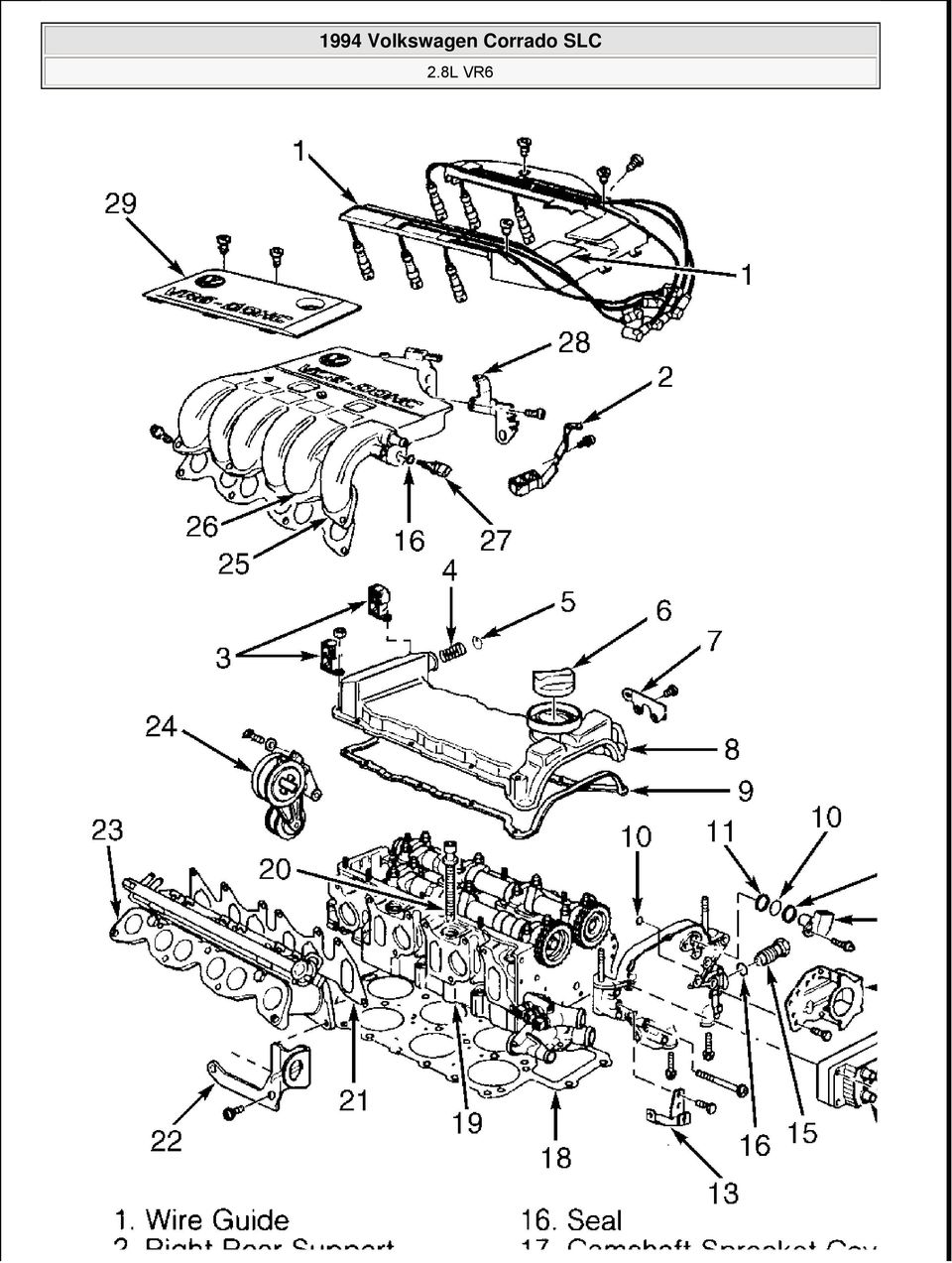
7 Fig. 4: Identifying Cylinder Head 2. Remove camshaft position sensor, "O" ring and spacer ring. Remove bracket for 42-pin connector and water pump. Remove ignition coil, chain tensioner and seal. Remove camshaft sprocket cover. Remove cylinder head bolts in reverse order of installation. See Fig. 6. Replace cylinder head bolts after loosening or removing. Inspection Thoroughly clean all gasket mating surfaces. Check cylinder head for warpage. Maximum warpage is.004" (.10 mm). Check minimum cylinder head height and replace cylinder head (if necessary). See CYLINDER HEAD table under ENGINE SPECIFICATIONS. NOTE: DO NOT reuse antifreeze after replacing cylinder block, cylinder head, head gasket, radiator and/or heater core. Installation 1. Remove sealer from the two 3-mm holes and replace with new sealer. See Fig. 5. Install gasket onto guide pins. Guide pins should be located near bolt hole No. 12 and No. 20. See Fig Install cylinder head onto cylinder block. Do not use any type of sealant. Install head bolts and tighten by hand. Tighten cylinder head bolts (in 4 steps) in sequence to specification. See Fig. 6. See TORQUE SPECIFICATIONS. Fig. 5: Sealing Cylinder Head 3-mm Holes

8 Fig. 6: Cylinder Head Bolts Tightening Sequence CRANKSHAFT OIL SEAL Removal Install 8-mm bolt in belt tensioner hole and remove accessory drive belt. See Fig. 2. Remove vibration damper. Loosen inner section of Oil Seal Extractor (3203) about 3 turns (4 mm) and lock in position with knurled screw. Turn inner section of oil seal extractor until seal is removed. Installation Place guide Sleeve (3266/1) on crankshaft. Push oil seal over guide sleeve. Using Oil Seal Installer (3266) and vibration damper bolt, press oil seal in completely. See Fig. 7. Reverse removal procedure to complete installation.
 and vibration damper bolt, press oil seal in completely. See Fig. 7.")
9 Fig. 7: Installing Crankshaft Oil Seal TIMING CHAIN Removal 1. Removal and installation procedure is not available from manufacturer. Ensure crankshaft is aligned at TDC. Remove transaxle and bellhousing assembly. Remove torque converter or clutch assembly (as applicable). Remove valve cover. Remove camshaft sprocket cover and intermediate shaft cover. Match mark all components to ensure reassembly in original position. 2. Mark timing chains for direction of rotation. Align and install Camshaft Guide (3268) onto cylinder head bolts. See Fig. 8. Remove upper and lower chain tensioners. If necessary, remove intermediate sprocket and camshaft sprocket bolts. Remove the timing chain. See Fig. 9.
 onto cylinder head bolts. See Fig. 8. Remove upper and lower chain tensioners.")
10 Fig. 8: Installing Camshaft Guide Onto Cylinder Head

11 Fig. 9: Exploded View Of Timing Chain & Related Components Installation

12 Leave Camshaft Guide (3268) installed. Ensure crankshaft is aligned at TDC. See Fig. 10. Ensure intermediate shaft is correctly aligned. See Fig. 11. Install timing chain on sprockets. Reverse removal procedure to complete installation

13
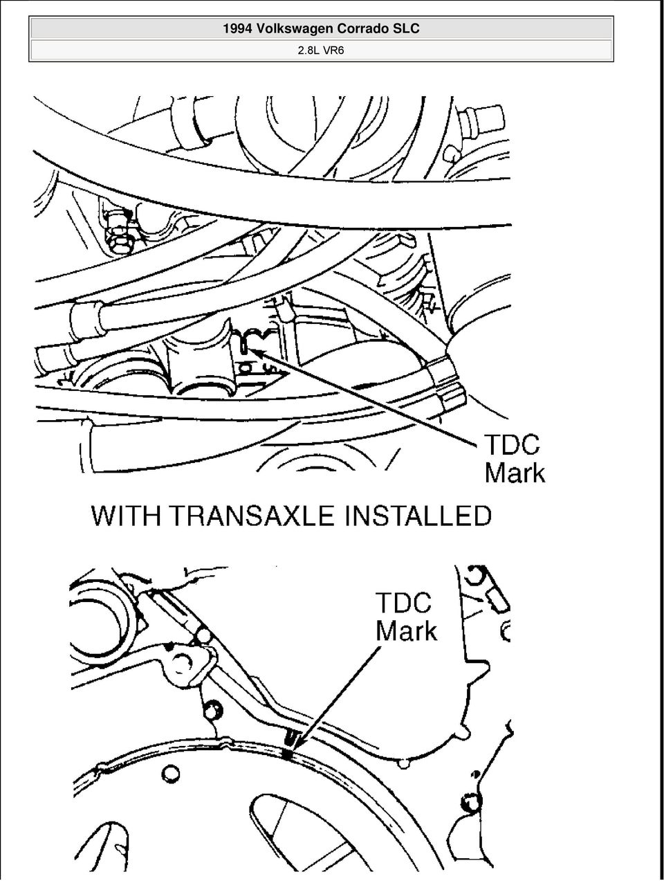
14 Fig. 10: Aligning Crankshaft At TDC Fig. 11: Aligning Intermediate Shaft At TDC CAMSHAFT Removal Remove valve cover. Place crankshaft at TDC. Remove ignition coil. Remove double chain tensioner. Remove camshaft sprocket cover with camshaft position sensor attached. Remove camshaft sprockets. Mark timing chains for direction of rotation. If removing camshaft for cylinders 1, 3 and 5, remove bearing caps

15 No. 1 and No. 7 first then remove bearing caps No. 3 and No. 5. If removing camshaft for cylinders 2, 4 and 6, remove bearing cap No. 4 first then remove bearing caps No. 2 and No. 6. Remove camshafts. Inspection Check camshaft bearing oil clearance. See CAMSHAFT table under ENGINE SPECIFICATIONS. If oil clearance exceeds specification, install new camshaft and recheck clearance. If clearance still exceeds specification, replace cylinder head. Installation 1. Lubricate all contact surfaces. When installing bearing caps, ensure identification mark on bearing cap is readable from exhaust manifold side and arrow points toward vibration damper. See Fig If installing camshaft for cylinders No. 1, 3 and 5, tighten bearing caps No. 3 and 5 alternately in a diagonal sequence to 15 ft. lbs. (20 N.m). Repeat procedure for bearing caps No. 1 and If installing camshaft for cylinders No. 2, 4 and 6, tighten bearing caps No. 2 and 6 alternately in a diagonal sequence to 15 ft. lbs. (20 N.m). Repeat procedure for bearing cap No To complete installation, reverse removal procedure. Ensure timing marks are properly aligned. If lifters are charged with oil, allow 30 minutes for lifters to bleed down before starting engine. Otherwise valves may come in contact with pistons.

16 Fig. 12: Installing Camshafts Into Cylinder Head VALVE LIFTERS Removal & Installation Remove camshaft. See CAMSHAFT. Remove valve lifters from cylinder head. Note position of each lifter. If lifters are reused, they MUST be installed in original position. If replacement lifters are charged with oil, allow 30 minutes for lifters to bleed down before starting engine. Otherwise, valves may come in contact with pistons. To complete installation, reverse removal procedure. WATER PUMP NOTE: Coolant/water mixture should be used at all times. Removal 1. Obtain radio security code. Turn ignition off and wait for 20 seconds. Disconnect negative battery

17 cable. Drain cooling system. Disconnect front exhaust pipe from catalytic converter. 2. Install 8-mm bolt in belt tensioner hole and remove drive belt. See Fig. 2. Remove ignition cable guide. Disconnect front and rear motor mounts. Attach Engine Sling (2024A) to engine. See Fig Lift engine enough to access water pump. Secure pulley using Spanner Wrench (VAG 1590). Remove water pump bolts. Push engine toward left side and remove water pump. Installation When installing motor mounts, ensure that recess on engine bracket fits into mounting tab of bonded rubber bushing. Hand tighten motor mount bolts and light rock engine to ensure motor mounts are fully seated. To complete installation, reverse removal procedure. OIL PAN Information is not available from manufacturer. OVERHAUL CYLINDER HEAD Cylinder Head Clean all gasket mating surfaces. Check cylinder head for warpage. Ensure warpage does not exceed.004" (0.1 mm). Valve Stem Oil Seals With valve springs removed, remove oil seals using Valve Seal Remover (3047A). To install new oil seal, slide plastic sleeve over valve stem. Lubricate new oil seal. Using Valve Seal Installer (3129), push oil seal on valve guide. Valve Guides 1. Check valve-to-guide clearance specification. See CYLINDER HEAD table under ENGINE SPECIFICATIONS. If valve guides have previously been replaced, replace cylinder head. 2. To replace valve guide, press guide out from camshaft side. Lubricate guide and press in cold cylinder head (from camshaft side) until shoulder makes contact. DO NOT exceed one ton pressure. Ream guides to proper valve-to-guide clearance. See CYLINDER HEAD table under ENGINE SPECIFICATIONS. Valve Seats 1. Check valve seats before any other cylinder head service. Insert the valve and hold firmly against the valve seat. Measure valve stem tip-to-cylinder head distance. See Fig. 13. This measurement determines installed valve height. Subtract measured distance from minimum specification. See MINIMUM VALVE INSTALLED HEIGHT table. 2. The difference is maximum refacing allowable for valve and seat. If valve installed height is too low or too high, lifters will not work correctly. Replace cylinder head assembly. MINIMUM VALVE INSTALLED HEIGHT Application In. (mm)

18 Intake Valve 1.33 (33.9) Exhaust Valve 1.34 (34.1) Fig. 13: Measuring Valve Installed Height Valves Measure valve length, stem diameter and valve margin. If not within specification, replace valves. Lap valves by hand or replace as necessary. See VALVES table under ENGINE SPECIFICATIONS. HYDRAULIC LIFTER TEST To determine weak or noisy lifter, position camshaft lobe high point upward. Using a piece of wood, push lifter down. See Fig. 14. If lifter moves down more than.004" (.10 mm), replace lifter. If lifter moves less than.004" (.10 mm), lifter is okay. Repeat procedure for remaining lifters. CAUTION: If replacement lifter is charged with oil, allow 30 minutes for lifter to bleed
, replace lifter. If lifter moves less than.004\" (.10 mm), lifter is okay. Repeat procedure for remaining lifters.")
19 down before starting engine. Otherwise, valves may come in contact with pistons. Fig. 14: Depressing Lifter CYLINDER BLOCK ASSEMBLY Piston & Rod Assembly 1. Make sure piston, rod and rod caps are marked with matching cylinder number prior to removal. Ensure arrow on top of piston points toward pulleys. Ensure marks on rod and cap are positioned correctly. See Fig. 15. Rod cap bolts and nuts must be replaced after removing or loosening.

20

21 Fig. 15: Assembling Piston & Rod 2. Mark piston in relation to pin. Remove circlips from ends of pin bore. Use Piston Pin Replacer/Installer (VW 222A) to remove and install piston pin. If pin is too tight, heat piston to 140 F (60 C). Ensure rod is properly positioned with piston. Fitting Pistons Measure clearances with cylinder block supported on work bench. Check clearance of piston-to-cylinder bore. Piston diameter is stamped on top of piston in millimeters. PISTON-TO-CYLINDER BORE DIMENSIONS Size Piston Diameter Cylinder Bore Standard 3.188" (80.98 mm) 3.189" (81.01 mm) 1st Over 3.208" (81.49 mm) 3.209" (81.51 mm) 2nd Over 3.228" (81.98 mm) 3.229" (82.01 mm) Piston Rings 1. Measure ring end gap. Measure ring side clearance with piston. Replace if necessary. See PISTONS, PINS & RINGS table under ENGINE SPECIFICATIONS. 2. Install rings on piston with TOP mark facing upward. Recessed edge on outside of center ring must face piston pin (down). Position ring gaps on piston at 120 degree intervals. Connecting Rod Bearings Mark rod caps for reinstallation. Use Plastigage to measure bearing clearances. Measure connecting rod side play. Replace or machine as necessary. See CRANKSHAFT, MAIN & CONNECTING ROD BEARINGS table under ENGINE SPECIFICATIONS. Tighten evenly to specification in several steps. See TORQUE SPECIFICATIONS. Crankshaft & Main Bearings Main bearing caps are marked with matching journal for installation in original position. See Fig. 16. Measure crankshaft end play. See THRUST BEARING.
22
23 Fig. 16: Exploded View Of Crankshaft Assembly Thrust Bearing Insert feeler gauge between No. 5 main bearing and crankshaft thrust face to measure end play. See Fig. 16. Replace thrust bearing as necessary. See CRANKSHAFT, MAIN & CONNECTING ROD BEARINGS table under ENGINE SPECIFICATIONS. Cylinder Block Check cylinder bore for wear, out-of-round and taper. Check cylinder block for warpage. See CYLINDER BLOCK table under ENGINE SPECIFICATIONS. ENGINE OILING ENGINE LUBRICATION SYSTEM Crankcase Capacity See CRANKCASE CAPACITY table. CRANKCASE CAPACITY Application With Filter Replacement Without Filter Replacement Specification 5.8 Qts. (5.5L) 5.3 Qts. (5.0L) Oil Pressure Check oil pressure with engine at warm operating temperature. Minimum oil pressure at 2000 RPM is 29 psi (2.0 kg/cm 2 ). If oil pressure is incorrect, check oil pump and oil pressure relief valve. OIL PUMP Removal & Installation Remove oil pan. Remove oil pump attaching bolts and remove oil pump assembly. To install, reverse removal procedure. Inspection Check oil pump housing, gears and pressure relief valve for damage or excessive wear. See Fig. 17. Repair or replace as an assembly.
24 Fig. 17: Oil Pump Assembly TORQUE SPECIFICATIONS TORQUE SPECIFICATIONS Application Ft. Lbs. (N.m)
25 A/C Bracket-To-Engine Bolt 18 (25) Axle Shaft-To-Transaxle Drive Flange Bolt 33 (45) Camshaft Bearing Cap Bolt 15 (20) Camshaft Sprocket Bolt 74 (100) Connecting Rod Bolt Step 1 22 (30) Step 2 Additional 1/4 Turn (90 Degrees) Crankshaft Main Bearing Cap Bolt Step 1 22 (30) Step 2 Additional 1/2 Turn (180 Degrees) Cylinder Head Bolt (1) Step 1 30 (40) Step 2 44 (60) Step 3 Additional 1/4 Turn (90 Degrees) Step 4 Additional 1/4 Turn (90 Degrees) Engine Bracket (Front) 44 (60) Engine Bracket (To Body) 44 (60) Engine-To-Transaxle M12 Bolt 59 (80) M10 Bolt 44 (60) M7 Bolt (2) M6 Bolt (2) Exhaust Manifold-To-Cylinder Head Bolt & Nut 18 (25) Exhaust Pipe-To-Catalytic Converter Bolt 18 (25) Exhaust Pipe-To-Manifold Nut 30 (40) Flywheel-To-Crankshaft Bolt Step 1 44 (60) Step 2 Additional 1/4 Turn (90 Degrees) Guide Rail Bolt 15 (20) Intake Manifold 18 (25) Intermediate Shaft Sprocket Bolt 74 (100) Oil Pan Bolt 11 (15) Oil Pan Drain Plug 22 (30) Oil Pressure Switch 18 (25) Oil Pump Cover Long Bolt (2) Oil Pump Cover Short Bolt 18 (25) Power Steering Pump Bracket Bolt 18 (25) Pressure Plate Bolt 15 (20) Starter Mount Bolt 44 (60) Timing Chain (Double Row) Tensioner Nut 22 (30) Torque Converter-To-Carrier Plate Bolt 22 (30) Vibration Damper Bolt
26 Step 1 89 (120) Step 2 Additional 1/4 Turn (90 Degrees) Water Pump Pulley Bolt 18 (25) Water Pump Housing-To-Engine Bolt 15 (20) INCH Lbs. (N.m) Fuel Rail Bolt (Lower) 89 (10) Intermediate Shaft Retainer Plate Bolt 89 (10) Sensor Wheel Bolt Step 1 89 (10) Step 2 Additional 1/4 Turn (90 Degrees) Timing Chain (Single Row) Tensioner Bolt 89 (10) Valve Cover Retaining Nut 89 (10) (1) Never reuse cylinder head bolt(s) when servicing. (2) Tighten bolt to 89 INCH lbs. (10 N.m). ENGINE SPECIFICATIONS GENERAL SPECIFICATIONS GENERAL SPECIFICATIONS Application Specification Displacement 170 Cu. In. Bore 3.19" (81.0 mm) Stroke 3.56" (90.3 mm) Compression Ratio 10.0:1 Fuel System Motronic SFI RPM 5800 Torque Ft. RPM 4200 CRANKSHAFT, MAIN & CONNECTING ROD BEARINGS CRANKSHAFT, MAIN & CONNECTING ROD BEARINGS Application In. (mm) Crankshaft End Play Standard ( ) Service Limit.012 (.30) Runout.001 (.03) Main Bearings Journal Diameter ( ) Journal Out-Of-Round.001 (.03) Journal Taper.001 (.03) Oil Clearance
27 Standard ( ) Service Limit.0039 (.100) Connecting Rod Bearings Journal Diameter ( ) Journal Out-Of-Round.001 (.03) Journal Taper.001 (.03) Oil Clearance Standard ( ) Service Limit.0039 (.100) PISTONS, PINS & RINGS PISTONS, PINS & RINGS Application In. (mm) Pistons Clearance.0016 (.040) Diameter (80.99) Pins Diameter (1) Piston Fit Interference Fit Rod Fit Interference Fit Rings No. 1 End Gap Standard ( ) Service Limit.0039 (.100) Side Clearance Standard ( ) Service Limit.006 (.15) No. 2 End Gap Standard ( ) Service Limit.0039 (.100) Side Clearance Standard ( ) Service Limit.006 (.15) No. 3 (Oil) End Gap Standard ( ) Service Limit.0039 (.100) Side Clearance ( ) (1) Information is not available from manufacturer.
28 CYLINDER BLOCK CYLINDER BLOCK Application In. (mm) Cylinder Bore Standard Diameter (81.01) Maximum Taper.0032 (.08) Maximum Out-Of-Round.001 (.03) OIL PUMP OIL PUMP Application Pump Gear Clearance Radial (Maximum) Axial (Maximum) Specification.008" (.20 mm).0039" (.100 mm) VALVES VALVES Application Specification Intake Valves Face Angle 45 Head Diameter 1.535" (39.00 mm) Length " ( mm) (1) (2) Minimum Margin Stem Diameter.2744" (6.97 mm) Exhaust Valves Face Angle 45 Head Diameter 1.346" (34.20 mm) Length " ( mm) Minimum Margin Stem Diameter (1) (2) (1) DO NOT machine valves; hand lap only. (2) Information is not available from manufacturer..2736" (6.95 mm) CYLINDER HEAD CYLINDER HEAD Application Cylinder Head Height (Minimum) Maximum Warpage Valve Seats Intake Valve Specification 5.492" (139.5 mm).0039" (.100 mm)
29 Seat Angle 45 Seat Width " ( mm) Exhaust Valve Seat Angle 45 Seat Width " ( mm) Valve Guides Intake Valve Valve Guide Installed Height (1) Oil Clearance (2).040" (1.0 mm) Exhaust Valve Valve Guide Installed Height (1) Valve Stem-to-Guide Oil Clearance (1) Valve guide shoulder flush with cylinder head. (2).051" (1.30 mm) (2) New valve installed in cylinder head. Dial indicator used to measure valve rock in guide. CAMSHAFT CAMSHAFT Application In. (mm) End Play.006 (.15) Oil Clearance.0039 (.100) Maximum Runout.0004 (.01) Maximum
1993 VOLKSWAGEN ENGINES 2.5L 5-Cylinder. EuroVan
 Article Text ARTICLE BEGINNING 1993 VOLKSWAGEN ENGINES 2.5L 5-Cylinder EuroVan * PLEASE READ THIS FIRST * NOTE: For engine repair procedures not covered in this article, see ENGINE OVERHAUL PROCEDURES
Cooling system components, removing and installing
 Page 1 of 34 19-1 Cooling system components, removing and installing WARNING! The cooling system is pressurized when the engine is warm. When opening the expansion tank, wear gloves and other appropriate
Volkswagen New Beetle 2.0 Liter 4-cyl General, Engine (Engine Code AEG) 15 Engine- Cylinder head, Valvetrain (Page GR-15)
 15 Engine- Cylinder head, Valvetrain (Page GR-15)") 15 Engine- Cylinder head, Valvetrain (Page GR-15) Cylinder head, removing and installing Compression, checking Valve train, servicing Camshaft oil seal, replacing Camshaft, removing and installing Hydraulic
15 Engine- Cylinder head, Valvetrain (Page GR-15) Cylinder head, removing and installing Compression, checking Valve train, servicing Camshaft oil seal, replacing Camshaft, removing and installing Hydraulic
2001 Nissan Pathfinder LE 2001 ENGINES 3.5L V6
 2001 ENGINES 3.5L V6 ENGINE IDENTIFICATION NOTE: For repair procedures not covered in this article, see ENGINE OVERHAUL PROCEDURES article in GENERAL INFORMATION. Engine can be identified by fourth character
Volkswagen Jetta, Golf, GTI 1999, 2000 Brake System 47 Brakes - Hydraulic Components (Page GR-47)
") 47 Brakes - Hydraulic Components (Page GR-47) FS III front brake calipers, servicing Front brake caliper piston, removing and installing FN 3 front brake calipers, servicing Front caliper piston, removing
47 Brakes - Hydraulic Components (Page GR-47) FS III front brake calipers, servicing Front brake caliper piston, removing and installing FN 3 front brake calipers, servicing Front caliper piston, removing
EM 58. 19. REMOVE NO. 2 MANIFOLD STAY (a) Remove the bolt, nut and stay.
 Remove the bolt, nut and stay.") 57 ROVAL 1. DISCHARGE FUEL SYST PRESSURE (See page FU-9) 2. DISCONNECT CABLE FROM NEGATIVE BATTERY TERMINAL CAUTION: Wait at least 90 seconds after disconnecting the cable from the negative (-) battery
57 ROVAL 1. DISCHARGE FUEL SYST PRESSURE (See page FU-9) 2. DISCONNECT CABLE FROM NEGATIVE BATTERY TERMINAL CAUTION: Wait at least 90 seconds after disconnecting the cable from the negative (-) battery
Cooling system components, removing and installing
 Engine BHW Cooling system components, removing and installing Page 1 / 24 19-1 Cooling system components, removing and installing Warning! When doing any repair work, especially in the engine compartment,
Volkswagen B3 Passat Manual Transmission 02A 34 Manual Transmission - Controls, Assembly (Page GR-34) 02A 5-speed. Gearshift cable/lever installing
 02A 5-speed. Gearshift cable/lever installing") 34 Manual Transmission - Controls, Assembly (Page GR-34) 02A 5-speed Gearshift cable/lever installing Gearshift housing repairing Gearshift lever repairing lever/relay lever, installing Gearshift mechanism
34 Manual Transmission - Controls, Assembly (Page GR-34) 02A 5-speed Gearshift cable/lever installing Gearshift housing repairing Gearshift lever repairing lever/relay lever, installing Gearshift mechanism
STEERING SYSTEM - POWER
 STEERING SYSTEM - POWER 1990 Nissan 240SX 1990 STEERING Nissan - Power Rack & Pinion Axxess, Maxima, Pulsar NX, Sentra, Stanza, 240SX, 300ZX DESCRIPTION The power steering system consists of a rack and
Turbocharger system components, servicing
 21-1 Turbocharger system components, servicing Engine codes: AAZ, 1Z, AHU Observe rules of cleanliness Page 21-10 Turbocharger hoses and lines, connecting Page 21-11 WARNING! Do not re-use any fasteners
ARTICLE BEGINNING APPLICATION IDENTIFICATION DESCRIPTION LUBRICATION & ADJUSTMENT TROUBLE SHOOTING. MANUAL TRANSMISSIONS Saab 5-Speed Transaxle
 Article Text ARTICLE BEGINNING MANUAL TRANSMISSIONS Saab 5-Speed Transaxle APPLICATION TRANSMISSION APPLICATION ÄÄÄÄÄÄÄÄÄÄÄÄÄÄÄÄÄÄÄÄÄÄÄÄÄÄÄÄÄÄÄÄÄÄÄÄÄÄÄÄÄÄÄÄÄÄÄÄÄÄÄÄÄÄÄÄÄÄÄÄ Vehicle Application Transmission
2003 ACCORD - Automatic Transmission Removal
 2003 ACCORD - Automatic Transmission Removal Special Tools Required Engine support hanger, A and Reds AAR-T-12566 Engine hanger balancer bar VSB02C000019 Front subframe adapter VSB02C000016 These special
BR150 Pmi Baja Reaction 150cc Go Kart (VIN PREFIX L4VM)
") Page 1 of 21 Product Information Baja Web > Product Information > Parts Lists > GOKART > BR150 Pmi Baja Reaction 150cc Go Kart (VIN PREFIX L4VM) BR150 Pmi Baja Reaction 150cc Go Kart (VIN PREFIX L4VM)
Page 1 of 21 Product Information Baja Web > Product Information > Parts Lists > GOKART > BR150 Pmi Baja Reaction 150cc Go Kart (VIN PREFIX L4VM) BR150 Pmi Baja Reaction 150cc Go Kart (VIN PREFIX L4VM)
REMOVAL AND INSTALLATION
 303-01C-1 REMOVAL AND INSTALLATION Engine Body On Special Tool(s) Adapter For 303-D043 303-D043-02 or equivalent Special Tool(s) 303-01C-1 Turbocharger Lifting Bracket 303-1266 Wrench, Fan Clutch Nut 303-214
Cooling system components, removing and installing
 Volkswagen Touareg 3.2 - Cooling system components, removing and installing Page 1 / 24 19-1 Cooling system components, removing and installing Warning! Hot steam may escape when opening expansion tank.
P7100 PUMP INSTALLATION INSTRUCTIONS Diesel Care & Performance Inc
 P7100 PUMP INSTALLATION INSTRUCTIONS Diesel Care & Performance Inc Installation Timing Pin Location CAUTION: Before installing the injection pump, be sure that number 1 cylinder is at the Top Dead Center
Cylinder head, removing and replacing
 15-1 Cylinder head, removing and replacing WARNING! Do not re-use any fasteners that are worn or deformed in normal use. Some fasteners are designed to be used only once, and are unreliable and may fail
Volkswagen New Beetle 2.0 Liter 4-cyl General, Engine (Engine Code AEG) 17 Engine-Lubrication system (Page GR-17)
 17 Engine-Lubrication system (Page GR-17)") 17 Engine-Lubrication system (Page GR-17) Lubrication system components, removing and installing Oil pan, removing and installing Oil pressure and oil pressure switch, checking Dynamic oil pressure warning
17 Engine-Lubrication system (Page GR-17) Lubrication system components, removing and installing Oil pan, removing and installing Oil pressure and oil pressure switch, checking Dynamic oil pressure warning
Cooling system components, servicing
 19-1 Cooling system components, servicing WARNING! The cooling system is pressurized when the engine is warm. When opening the expansion tank, wear gloves and other appropriate protection, cover the cap
Volkswagen Jetta, Golf, GTI 1999, 2000 Brake System 46 Brakes - Mechanical Components (Page GR-46)
") 46 Brakes - Mechanical Components (Page GR-46) Front brakes Brake pads, removing and installing Brake pads, removing and installing FN 3 brake caliper, servicing FS III brake caliper, servicing Rear wheel
46 Brakes - Mechanical Components (Page GR-46) Front brakes Brake pads, removing and installing Brake pads, removing and installing FN 3 brake caliper, servicing FS III brake caliper, servicing Rear wheel
2003 Audi A4. AUDI' '3.0L V6 - AVK Engine - A4 & A6
 Installation (A4) CAUTION: Before installation, ensure camshafts are aligned, crankshaft is locked in place and camshaft gear bolts are loose as described in removal procedures. When turning camshaft,
Volkswagen B3 Passat General-Engine 4 CYL. 19 Engine - Cooling System (Page GR-19)
") 19 Engine - Cooling System (Page GR-19) Cooling system draining and filling general information Body components, layout Engine components, layout Radiator fan run-on checking Recommended mixture ratios
19 Engine - Cooling System (Page GR-19) Cooling system draining and filling general information Body components, layout Engine components, layout Radiator fan run-on checking Recommended mixture ratios
Volkswagen Jetta, Golf, GTI 1999, 2000 2.8 Liter VR6 2V Engine Mechanical, Engine Code(s): AFP 17 Engine-Lubrication (Page GR-17)
: AFP 17 Engine-Lubrication (Page GR-17)") 17 Engine-Lubrication (Page GR-17) Lubrication system components, removing and installing Oil filter housing, disassembling and assembling Oil pan, removing and installing Oil pressure and oil pressure
17 Engine-Lubrication (Page GR-17) Lubrication system components, removing and installing Oil filter housing, disassembling and assembling Oil pan, removing and installing Oil pressure and oil pressure
STATE UNIVERSITY OF NEW YORK COLLEGE OF TECHNOLOGY CANTON, NEW YORK COURSE OUTLINE AUTO 220 INTERNAL COMBUSTION ENGINES
 STATE UNIVERSITY OF NEW YORK COLLEGE OF TECHNOLOGY CANTON, NEW YORK COURSE OUTLINE AUTO 220 INTERNAL COMBUSTION ENGINES Prepared By: BRANDON BALDWIN CANINO SCHOOL OF ENGINEERING TECHNOLOGY AUTOMOTIVE TECHNOLOGY
Model No: VS4815 1. SAFETY INSTRUCTIONS VS4800 2. INTRODUCTION & APPLICATIONS VS4815 3. CONTENTS. 2.1 Introduction. 2.
 Instructions for: Petrol Engine Twin Camshaft Setting / Locking Tool Kit - (incorporating Vanos Alignment) - BMW N42 & N46 Engines Model No: VS4800 Associated kit: Camshaft/Carrier Bracket Remover & Installer
1/29/2008 DR70. Baja Motorsports Inc. P.O. Box 61150 Phoenix, AZ 85082 Toll Free: 888-863-2252 PART NUMBERS PRICES ARE SUBJECT TO CHANGE 1 of 43
 DR70 Toll Free: 888-863-2252 PART NUMBERS PRICES ARE SUBJECT TO CHANGE 1 of 43 CYLINDER & CYLINDER HEAD 1 DR70-001 883099044472 CYLINDER 1 1 2 DR70-002 883099044489 GASKET, CYLINDER 1 1 3 DR70-003 883099044496
Marine Diesel Engine VF4 VF5 VF4.140E VF4.170E VF5.220E VF5.250E. Service Manual
 Marine Diesel Engine VF4 VF5 Service Manual VF4.140E VF4.170E VF5.220E VF5.250E Copyright 2009 Vetus N.V. Schiedam Holland Reproduction of text and illustrations, in whole or in part, is strictly prohibited.
1/29/2008 DR125 / DR150. Baja Motorsports Inc. P.O. Box 61150 Phoenix, AZ 85082 Toll Free: 888-863-2252 PARTS AND PRICES ARE SUBJECT TO CHANGE 1 of 55
 DR125 / DR150 Toll Free: 888-863-2252 PARTS AND PRICES ARE SUBJECT TO CHANGE 1 of 55 CYLINDER HEAD ASSY. 1 125-001 883099006937 CYLINDER HEAD COVER 1 1 2 125-002 883099006944 BOLT M6X28 2 3 3 125-003 883099006951
CYLINDER HEAD (4A FE)
") EM81 CYLINDER HEAD (4AFE) COMPONENTS EM82 ENGINE MECHANICAL REMOVAL OF CYLINDER HEAD (See page EM81) 1. DISCONNECT CABLE FROM NEGATIVE TERMINAL OF BATTERY CAUTION: Work must be started after approx. 20
EM81 CYLINDER HEAD (4AFE) COMPONENTS EM82 ENGINE MECHANICAL REMOVAL OF CYLINDER HEAD (See page EM81) 1. DISCONNECT CABLE FROM NEGATIVE TERMINAL OF BATTERY CAUTION: Work must be started after approx. 20
Adjustment Data MAZDA - 626-2.0 Comprex D - RF-CX
 Adjustment Data MAZDA - 626-2.0 Comprex D - RF-CX Engine (general) Engine code RF Capacity 1998 (cc) Idle speed 725 ± 25 Valve clearance Valve clearance Cold Inlet 0.25 (mm) Exhaust 0.35 (mm) Compression
Kobelco Extended Warranty Program. www.kobelco-europe.com
 Kobelco Extended Warranty Program www.kobelco-europe.com Kobelco Extended Warranty is a convenient, value added way to give your Kobelco customers added security and peace of mind. Benefits of the Kobelco
Cooling system components, removing and installing
 Page 1 of 30 19-1 Cooling system components, removing and installing Notes: When the engine is warm the cooling system is under pressure. If necessary release pressure before commencing repair work. Secure
1/29/2008 DR50. Baja Motorsports Inc. P.O. Box 61150 Phoenix, AZ 85082 Toll Free: 888-863-2252 PART NUMBERS PRICES ARE SUBJECT TO CHANGE 1 of 45
 DR50 Toll Free: 888-863-2252 PART NUMBERS PRICES ARE SUBJECT TO CHANGE 1 of 45 CYLINDER & CYLINDER HEAD Part UPC Number Description Baja Description 1 DR50-001 842645074424 CYLINDER 1 1 2 DR50-002 842645074431
Engine, disassembling and assembling
 13-1 Engine, disassembling and assembling Note: Replace the oil cooler and thoroughly clean the oil passages if you find metal shavings or larger quantities of small metal particles in the engine oil,
Rear wheel brakes, servicing. Стр. 1 из 45. Note:
 Volkswagen Touareg - Rear wheel brakes, servicing Стр. 1 из 45 46-2 Rear wheel brakes, servicing Rear brakes, FN 44 brake caliper, servicing Note: After replacing brake pads, depress brake pedal firmly
6-years/75,000 miles Comprehensive coverage Subsequent Owner Warranty $100 Deductible
 LINCOLN PREMIER LIMITED WARRANTY 6-years/75,000 miles Comprehensive coverage Subsequent Owner Warranty $100 Deductible Comprehensive Coverage Because Lincoln has always been a brand you can trust and respect,
DR50 Hensim Dirt Runner 49cc Dirt Bike (VIN PREFIX LLCH or LUAH)
") Page 1 of 21 Product Information Baja Web > Product Information > Parts Lists > DIRTBIKE > DR50 Hensim Dirt Runner 49cc Dirt Bike (VIN PREFIX LLCH or LUAH) DR50 Hensim Dirt Runner 49cc Dirt Bike (VIN PREFIX
Page 1 of 21 Product Information Baja Web > Product Information > Parts Lists > DIRTBIKE > DR50 Hensim Dirt Runner 49cc Dirt Bike (VIN PREFIX LLCH or LUAH) DR50 Hensim Dirt Runner 49cc Dirt Bike (VIN PREFIX
AXLE SHAFTS - FRONT. 1993 Toyota Celica DESCRIPTION REMOVAL, DISASSEMBLY, REASSEMBLY & INSTALLATION. 1993 DRIVE AXLES Toyota FWD Axle Shafts
 AXLE SHAFTS - FRONT 1993 Toyota Celica 1993 DRIVE AXLES Toyota FWD Axle Shafts Toyota; Celica DESCRIPTION Axle shafts transfer power from transaxle to driving wheels. All axle shafts consist of a shaft
Volkswagen Golf 5 2004-> VW Rabbit GTI 2006->
 Стр. 1 из 24 Volkswagen Golf 5 2004-> VW Rabbit GTI 2006-> 19-1 Cooling system components Warning! Hot steam may escape when opening expansion tank. Wear protective goggles and protective clothing to prevent
CAM-03, Camshaft Assembly Oil Seal Replacement
 CAM-03, Camshaft Assembly Oil Seal Replacement Tools Jack stands Floor Jack Metric Socket set Metric Wrench set Porsche Timing Belt Tension tool (P9201) Flywheel Lock (P9206) Balance Shaft Pin Spanner
2740 Whitten Rd Bldg 103 Memphis, TN 38133 Telephone 901-380-9290 Email Bwilliams@Dieselcare.net
 Fuel Injection Pump Replacement REMOVAL Diesel Care & Performance Inc 1. Disconnect negative battery terminal. 2. Remove throttle linkage. Fuel Injection Pump Bracket 3. Remove injection pump bracket.
3.0L V6 - VINS [H,R] & 3.0L V6 TURBO - VIN [C]
![3.0L V6 - VINS [H,R] & 3.0L V6 TURBO - VIN [C]](/thumbs/40/20870076.jpg "3.0L V6 - VINS [H,R] & 3.0L V6 TURBO - VIN [C]") 3.0L V6 - VINS [H,R] & 3.0L V6 TURBO - VIN [C] 1991 Nissan 300ZX 1991 NISSAN ENGINES 3.0L V6 Maxima, Pathfinder, Pickup, 300ZX * PLEASE READ THIS FIRST * NOTE: For engine repair procedures not covered
3.0L V6 - VINS [H,R] & 3.0L V6 TURBO - VIN [C] 1991 Nissan 300ZX 1991 NISSAN ENGINES 3.0L V6 Maxima, Pathfinder, Pickup, 300ZX * PLEASE READ THIS FIRST * NOTE: For engine repair procedures not covered
Engine. 204-1890 Strobe light, 110V 204-1891 Strobe light, 220V 204-458 Replacement bulb. 204-1057 Compression gauge. 204-166 Dial indicator
 The Strobe light checks the unit for: Balance of operating machinery RPM of motors, engine pulleys, fans, etc. Observe belt slippage Strobe light will stop action at speeds from 200 to 6000 RPM 204-1890
ENGINE COOLING SYSTEM
 ENGINE COOLING SYSTEM 1988 Toyota Celica 1987-88 TOYOTA Engine Cooling Systems Celica DESCRIPTION The basic liquid cooling system consists of a radiator, water pump, thermostat, cooling fan, pressure cap,
COOLING SYSTEM Section Page
 5 COOLING SYSTEM Section Page 5.1 COOLANT PRE-HEATER... 5-3 5.2 COOLANT PUMP NON-EGR ENGINE... 5-7 5.3 COOLANT PUMP EGR ENGINE... 5-13 5.4 FRONT CONNECTOR HOUSING NON-EGR ENGINE... 5-17 5.5 FRONT CONNECTOR
DR125 and DR150 Hensim Dirt Runner 125cc and 150cc Dirt Bike (VIN PREFIX LLCH or LUAH)
") Parts Lists - DR125 and DR150 Hensim Dirt Runner 125cc and 150cc Dirt Bike (VIN PR... Page 1 of 25 Product Information Baja Web > Product Information > Parts Lists > DIRTBIKE > DR125 and DR150 Hensim Dirt
Parts Lists - DR125 and DR150 Hensim Dirt Runner 125cc and 150cc Dirt Bike (VIN PR... Page 1 of 25 Product Information Baja Web > Product Information > Parts Lists > DIRTBIKE > DR125 and DR150 Hensim Dirt
illustration ref. no. description SWAG no. RS Kombi, Octavia Scout 4x4, Octavia 4x4 for: Octavia, Octavia Kombi
 Skoda protection Kit for strut 20 56 0003 - for: Fabia Skoda protection Kit for strut 30 56 0010 for: Felicia I, Felicia II - Skoda protection Kit for strut 30 56 0029, Octavia Kombi 4x4, Octavia RS, Octavia
13. REAR WHEEL/BRAKE/SUSPENSION
 13. REAR WHEEL/BRAKE/SUSPENSION 13 3.5~4.5kg-m 8.0~10.0kg-m 0.8~1.2kg-m 3.0~4.0kg-m 2.4~3.0kg-m 3.5~4.5kg-m 6.0~8.0kg-m 13-0 13. REAR WHEEL/BRAKE/SUSPENSION 13 REAR WHEEL/BRAKE/SUSPENSION SERVICE INFORMATION...
Service. Engine. Engine Model: General Motors 4.3 L Powertrain. Generator Models: 30--45 kw TP-6103 1/01
 Service Engine Engine Model: General Motors 4.3 L Powertrain Generator Models: 30--45 kw TP-6103 1/01 CAUTION Caution: In order to reduce the chance of personal injury and/or property damage, carefully
DR90. Baja Motorsports Inc. P.O. Box 61150 Phoenix, AZ 85082 Toll Free: 888-863-2252 PART NUMBERS AND PRICES ARE SUBJECT TO CHANGE 1 of 51
 DR90 Toll Free: 888-863-2252 PART NUMBERS AND PRICES ARE SUBJECT TO CHANGE 1 of 51 CYLINDER & CYLINDER HEAD 1 DR90-001 842645048166 CYLINDER 1 1 2 DR90-002 842645048173 GASKET, CYLINDER 1 1 3 DR90-003
1993 SUSPENSION Volkswagen Front. EuroVan
 Article Text ARTICLE BEGINNING 1993 SUSPENSION Volkswagen Front EuroVan DESCRIPTION FWD independent suspension is an double-wishbone type with torsion bars mounted on upper control arm. Wheel is supported
ENGINE FUEL FUEL FILTER... FUEL HEATER... INJECTOR... SUPPLY PUMP... COMMON RAIL... FUEL PRESSURE LIMITTER...
 FUEL FILTER............................ FUEL HEATER.......................... INJECTOR.............................. SUPPLY PUMP.......................... COMMON RAIL.......................... FUEL PRESSURE
SLP 1.85 Ratio Offset Rocker Arms with Valve Springs, LS3
 PART #50190 SLP 1.85 Ratio Offset Rocker Arms with Valve Springs, LS3 PACKING LIST Before installation, use this check list to make sure all necessary parts have been included. ITEM QTY CHECK PART NUMBER
Cooling system components
 Page 1 / 33 19-1 Cooling system components Caution! When doing any repair work, especially in the engine compartment, pay attention to the following due to clearance issues: Route lines of all types (e.g.
AUTO TRANS DIAGNOSIS Article Text 1998 Volkswagen Passat This file passed thru Volkswagen Technical Site - http://volkswagen.msk.
 AUTO TRANS DIAGNOSIS Article Text 1998 Volkswagen Passat This file passed thru Volkswagen Technical Site - http://volkswagen.msk.ru ARTICLE BEGINNING 1997-98 AUTOMATIC TRANSMISSIONS Volkswagen Shift Interlock
MEASURING WHEEL ALIGNMENT
 MEASURING WHEEL ALIGNMENT 2003-04 WHEEL ALIGNMENT Specifications & Procedures - Hummer - H2 Steering and vibration complaints are not always the result of improper alignment. One possible cause is wheel
The cylinder head bolts tightening stages have been updated as listed in Table 1.
 NUMBER: 07 EPA04 MBE 4000-6 S.M. REF.: 1.2.2 ENGINE: MBE 4000 DATE: November 2007 SUBJECT: CYLINDER HEAD BOLTS TIGHTENING STAGES PUBLICATION: 6SE412 The cylinder head bolts tightening stages have been
Assembly overview - fuel tank
 Assembly overview - fuel tank vw-wi://rl/n.en-gb.k02589829.wi::33090894.xml?xsl=3 Page 1 of 2 Assembly overview - fuel tank 1 - Fuel tank 2 - Sleeve When removing, support using engine and gearbox jack
ALLDATA Online - 2006 Dodge Truck RAM 2500 Truck 2WD L6-5.9L DSL Turbo VI... Service and Repair
 Page 1 of 15 Home Account Contact ALLDATA Log Out Help PAUL REDEHOFT Select Vehicle New TSBs Technician's Reference Component Search: OK 2006 Dodge Truck RAM 2500 Truck 2WD L6-5.9L DSL Turbo VIN C Conversion
TRANSMISSION INSTALLATION CONTENTS
 A Regal Beloit Company TRANSMISSION INSTALLATION CONTENTS RICHMOND 6-SPEED AND SUPER STREET 5-SPEED WITH OVER DRIVE TRANS AM, CAMARO, CHEVELLE, GTO, CUTLASS, WITH T-10/MUNCIE....2 RICHMOND 6-SPEED 1963
Fuel Injection Pump, Rotary (005-014)
") Fuel Injection Pump, Rotary View Related Topic Page 1 of 30 Fuel Injection Pump, Rotary (005-014) Table of Contents Summary General Information Preparatory Steps Remove Front Gear Train Rear Gear Train
Fuel Injection Pump, Rotary View Related Topic Page 1 of 30 Fuel Injection Pump, Rotary (005-014) Table of Contents Summary General Information Preparatory Steps Remove Front Gear Train Rear Gear Train
WORKSHOP MANUAL 50CC ENGINE HORIZONTAL LIQUID-COOLED CYLINDER
 Sales division Technical network leadership WORKSHOP MANUAL 50CC ENGINE HORIZONTAL LIQUID-COOLED CYLINDER Sales division Technical network leadership TABLE OF CONTENTS TABLE OF CONTENTS TABLE OF CONTENTS...
Wynn s Extended Care
 Wynn s Extended Care Every car deserves to receive the very best care... especially yours. How Do You Keep Your Reliable Transportation Reliable? Count on Wynn s Because Wynn s has been caring for cars
MANUAL TRANS OVERHAUL - TYPE 02J Article Text 1999 Volkswagen Golf This file passed thru Volkswagen Technical Site -
 MANUAL TRANS OVERHAUL - TYPE 02J Article Text 1999 Volkswagen Golf This file passed thru Volkswagen Technical Site - http://volkswagen.msk.ru ARTICLE BEGINNING 1998-99 MANUAL TRANSMISSIONS Volkswagen/Audi
Char-Lynn Hydraulic Motor. Repair Information. 10 000 Series. October, 1997
 Char-Lynn Hydraulic Motor October, 1997 Repair Information Geroler Motor Two Speed 001 27 Retainer inside bore of valve plate bearingless motors only 4 15 16 3 6 35 Parts Drawing 25 2 2 1 19 17 36 40 47
C O N T E N T S 1 ABOUT THIS PARTS LIST... 2 ENGINE GROUP... 3 3 CONTENTS-FRAME GROUP
 C O N T E N T S 1 ABOUT THIS PARTS LIST... 2 2 CONTENTS-ENGINE ENGINE GROUP ENGINE GROUP... 3 3 CONTENTS-FRAME GROUP FRAME GROUP... 5 4 ENGINE PARTS LIST... 9 5 FRAME PARTS LIST...37 1 ABOUT THIS PARTS
STEERING HANDLEBAR/FRONT WHEEL/ FRONT SHOCK ABSORBER
 14 14 STEERING HANDLEBAR/FRONT WHEEL/ SCHEMATIC DRAWING ------------------------------------------------- 14-1 SERVICE INFORMATION------------------------------------------------ 14-2 TROUBLESHOOTING-----------------------------------------------------
This is the civilian transfer case with the cooling loop only found in the driven gear half of the front case.
 INTRODUCTION The Transfer case used in the AMG Hummer is a New Venture Gear, model 242. This case has been in use for the H-1/Hummer since the early 1990 s. There have been modifications to the internal
ARTICLE BEGINNING APPLICATION & LABOR TIMES IDENTIFICATION DESCRIPTION & OPERATION. AUTOMATIC TRANSMISSIONS Volkswagen Type 01M
 Article Text ARTICLE BEGINNING AUTOMATIC TRANSMISSIONS Volkswagen Type 01M Cabrio, Golf, Golf III, GTI Jetta, Jetta III, Passat APPLICATION & LABOR TIMES APPLICATION & LABOR TIMES ÄÄÄÄÄÄÄÄÄÄÄÄÄÄÄÄÄÄÄÄÄÄÄÄÄÄÄÄÄÄÄÄÄÄÄÄÄÄÄÄÄÄÄÄÄÄÄÄÄÄÄÄÄÄÄÄÄÄÄÄ
Cylinder head gasket, replacement
 "VCC065612 EN 20110604" 1(7) Cylinder head gasket, replacement Special tools: 999 5098 Disconnect battery earth lead Drain coolant Remove heat shield over exhaust manifold. (Only the two bottom bolts on
Front axle components, overview
 just a test. Front axle components, overview 40-1 General Information Load bearing components and parts of the suspension must not be welded or straightened. Vehicles without drive axle must not be moved,
DR90. Baja Motorsports Inc. P.O. Box 61150 Phoenix, AZ 85082 Toll Free: 888-863-2252 PART NUMBERS AND PRICES ARE SUBJECT TO CHANGE 1 of 51
 DR90 Toll Free: 888-863-2252 PART NUMBERS AND PRICES ARE SUBJECT TO CHANGE 1 of 51 CYLINDER & CYLINDER HEAD Part UPC Number Description Baja Description 1 DR90-001 842645048166 CYLINDER 1 1 2 DR90-002
AUTOMOBILE MECHANIC STUDENT INTERNSHIP SKILLS LIST Provo School District
 AUTOMOBILE MECHANIC STUDENT INTERNSHIP SKILLS LIST Provo School District Repairs and overhauls automobiles, buses, trucks, and other automotive vehicles: Examines vehicle and discusses with customer or
Slide the new steering column shaft through the steering column from the driver compartment.
 Slide the new steering column shaft through the steering column from the driver compartment. Push the column shaft through the steering column until the machined end is out past the column lower bushing.
1 5 05-12 5 05-12. Additions, Revisions, or Updates
 5 05-12 1 5 05-12 SUBJECT DATE Cylinder Head May 2012 Additions, Revisions, or Updates Publication Number / Title Platform Section Title Change DDC-SVC-MAN-0023 EPA04 MBE 4000 Cylinder Head Additional
MOTOR VEHICLE MECHANIC REPAIR CATEGORIES
 Chapter 8: Motor Vehicle Mechanic Repair Categories Page 1 CHAPTER 8 MOTOR VEHICLE MECHANIC REPAIR CATEGORIES Section 8-1 REQUIREMENT Section 10 of the Motor Vehicle Service and Repair Act (MCL 257.1310)
Drive shaft, servicing
 Volkswagen Passat B6 - Drive shaft, servicing Стр. 1 из 41 40-7 Drive shaft, servicing Drive shafts, overview I - Assembly overview: Drive axle with CV joint VL100 40-7, Drive axle with CV joint VL100,
Front brakes (FN- 3), servicing
, servicing") j a t Front brakes (FN- 3), servicing 46-1 Front brakes, servicing Note: Install complete repair kit. After replacing brake pads and before moving vehicle, depress brake pedal several times firmly to properly
j a t Front brakes (FN- 3), servicing 46-1 Front brakes, servicing Note: Install complete repair kit. After replacing brake pads and before moving vehicle, depress brake pedal several times firmly to properly
11. COOLING SYSTEM 11-0 COOLING SYSTEM BET & WIN 50
 11 COOLING SYSTEM SERVICE INFORMATION------------------------------------------------ 11-1 TROUBLESHOOTING----------------------------------------------------- 11-1 RADIATOR ------------------------------------------------------------------
ENGINE Dinli 904 D1033-011
 ENGINE Dinli 904 D1033-011 ENGINE Model Item Part no Description Specification Quantity 01 E140000-01 E14 ENGINE 450C.C. 1 FENDER SEAT D1033-021 FENDER SEAT Model Item Part no Description Specification
COVERING MILLIONS Preferred Protection Plan, a Service Group Company www.sgifs.com PO Box 26830, Austin, TX 78755-0800.
 COVERING MILLIONS Preferred Protection Plan, a Service Group Company www.sgifs.com PO Box 26830, Austin, TX 78755-0800. 1-877-565-0816 PPP-308 0903 rev 0408 BENEFITS New and Pre-Owned Vehicles Preferred
System Saver 318 Air Compressor for Mack E-Tech and ASET Engines
 Maintenance Manual 31 System Saver 318 Air Compressor for Mack E-Tech and ASET Engines Revised 08-05 NON-THROUGH DRIVE THROUGH DRIVE Service Notes About This Manual This manual provides service and repair
Skills Standards MEDIUM/HEAVY DUTY TRUCK: DIESEL ENGINE REPAIR TECHNICIAN OD32151 ALIGNED WITH ASE/NATEF
 Skills Standards MEDIUM/HEAVY DUTY TRUCK: DIESEL ENGINE REPAIR TECHNICIAN OD32151 ALIGNED WITH ASE/NATEF Competency-Based Education: OKLAHOMA S RECIPE FOR SUCCESS BY THE INDUSTRY FOR THE INDUSTRY Oklahoma
MERCEDES FIRST EDITION - 2013
 FIRST EDITION - 2013 CONTENTS Accessories... 1 Hydraulic Jacks Air Intake... 2 Air Filter Charger Charging System Intake Charger Hose Intake Manifold Intake Pipe Air Filter Intercooler Charger Aircondition...
CHAPTER 65 TAIL ROTOR DRIVE SYSTEM. Section Title Page
 CHAPTER 65 TAIL ROTOR DRIVE SYSTEM Section Title Page 65-00 Description........................................ 65.1 65-10 Tail Rotor Drive Fan Shaft.............................. 65.1 65-20 Tail Rotor
Rail 001 112 2 Canvas, folding top 001 101 3 Rear panel 001 102 4 Stip in window, left 001 106 dto. right 001 107
 U 411 1 Rear view mirror, round, metall 13cm Ø 002 045 2 Raised airintake 002 060 3 Side panelling, front, left 002 030 Side panelling, front, right 002 031 4 Panelling left 002 051 dto. right 002 052
MINI EXTENDED SERVICE CONTRACTS
 MINI EXTENDED SERVICE CONTRACTS LESS WORRY, MORE WEEEE! CONTINUING COVERAGE FOR YOUR NEW, USED, OR CERTIFIED PRE-OWNED MINI. Whether your odometer is ticking toward the end of your original 4-year/50,000-mile
PET. Illustration 001-00. Pos Part Number Description Remark Qty Model. - 356 72 106 jack 1. - 356 72 108 operating rod 1. - 356 72 103 tool bag 1
 Model 959 0 0 00-00 7 6:56.0.00 tool and accessories tool - 7 06 jack - 7 0 operating rod - 7 03 tool bag - 7 0 spark plug wrench - 0 A ring wrench 36 MM - - tyre pressure gauge L 709 0-999 57 05 0 rim
SECTION G2: CABLE PROCESSOR MODULE MAINTENANCE
 SECTION G2: CABLE PROCESSOR MODULE MAINTENANCE Cable Processor Module overview WARNING! When tipping the Cable Processor Module back, (after removing the toggle arm pin), use extreme caution not to drop
VS4760.V2. Instructions for: Diesel Engine Setting/Locking Tool Kit Renault dci Engines. Model No: 1. SAFETY INSTRUCTIONS
 Instructions for: Diesel Engine Setting/Locking Tool Kit Renault dci Engines Model No: VS4760.V2 Thank you for purchasing a Sealey product. Manufactured to a high standard this product will, if used according
AXLE SHAFTS - FRONT. 1998 Pontiac Bonneville MODEL IDENTIFICATION DESCRIPTION & OPERATION TROUBLE SHOOTING REMOVAL & INSTALLATION
 AXLE SHAFTS - FRONT 1998 Pontiac Bonneville 1998-99 DRIVE AXLES FWD Axle Shafts - Cars - "C", "G" & "H" Bodies GM Aurora, Bonneville, Eighty Eight, LeSabre, LSS, Park Avenue, Regency, Riviera MODEL IDENTIFICATION
Information and Instructions
 Information and Instructions This shop manual contains several sections each covering a specific group of wheel type tractors. The Tab Index on the preceding page can be used to locate the section pertaining
Intake Manifold: Service and Repair
 2000 Chevy Truck S10/T10 P/U 2WD L4-2.2L VIN 4 Copyright 2008, ALLDATA 9.90 Page 1 Intake Manifold: Service and Repair Removal Procedure 1. Disconnect the battery negative cable. Refer to Battery Replacement.
Rexroth Hydraulic Pump A10VO Series User Manual
 Rexroth Hydraulic Pump A10VO Series User Manual Rexroth Hydraulic pump A10VO Series User Manual Revised 5/1/2009 Page 1 of 12 Functional Purpose This pump is preferred over a fixed displacement (gear)
Oregon Fuel Injection
 Corporate Office: P.O. Box 21121, VE Pump Removal and Installation Cummins Lock Timed Applications Removal Clean the exterior of the injection pump and mounting surfaces. 1. Disconnect the fuel return
AUTOMATIC TRANSMISSION
 23E-0-1 AUTOMATIC TRANSMISSION V5A51 CONTENTS GENERAL INFORMATION... 23E-0-3 1. SPECIFICATIONS... 23E-1-1 TRANSMISSION MODEL TABLE... 23E-1-1 GENERAL SPECIFICATIONS... 23E-1-2 SERVICE SPECIFICATIONS...
Table of Contents. Overview 1. Pump Disassembly 2. Control Disassembly / Reassembly 7. Pump Reassembly 13. Adjustment Procedures DR Control 19
 Table of Contents Overview 1 Pump Disassembly 2 Control Disassembly / Reassembly 7 Pump Reassembly 13 Adjustment Procedures DR Control 19 Adjustment Procedures DRG Control 20 Adjustment Procedures DFR
Mercedes 722.3 722.4
 96 Mercedes 7. 7. 5 6 7 8 - Clutch K - Brake Band B - Disc Brake B - Wide Planet Pinion 5 - One-Way Clutch F 6 - Clutch K 7 - Brake Band B 8 - Narrow Planet Pinion Int. Band Fwd. Band Rev. Clutch Direct
DO NOT attempt to repair hub and wheel bearing assembly.
 Page 1 of 6 HUB & WHEEL BEARINGS (WITH PULSE VACUUM HUBLOCK) DO NOT attempt to repair hub and wheel bearing assembly. Removal DO NOT remove hub lock assembly by prying on hub lock legs. This can crack
INSTRUCTIONS AND PARTS LIST FOR MODEL 70H & 75H HAND-OPERATED HYDRAULIC PRESS
 INSTRUCTIONS AND PARTS LIST FOR MODEL 70H & 75H HAND-OPERATED HYDRAULIC PRESS SETTING UP THE PRESS FOR OPERATION For shipping convenience, the gauge, pump handle, hoist crank, screw nose and base angles