Parts list and Notes for making a 10 hp 240V single phase to 240V 3-phase converter.
|
|
|
- Jacob Crawford
- 9 years ago
- Views:
Transcription
1
2 Parts list and Notes for making a 10 hp 240V single phase to 240V 3-phase converter. Introduction: This document describes typical parts and a schematic for building a single to three phase rotary converter. The parts listed were taken from the 1996 Grainger catalog #387 for convenience and having a point of common reference. Equivalent surplus parts can be used and will result in considerable savings of money at the expense of time and some study to be sure they are the electrical and functional equivalent. The reference designators refer to the attached schematic diagram. Tuning instructions are on the diagram and in some notes below. Electrical measuring equipment: The following equipment should be on hand when tuning up the converter. AC Volt meter with at least 370 VAC range. AC Clamp on ammeter with at least 100A capability. Both instruments can be combined if a FLUKE 30 is purchased. The FLUKE 30 is a combination digital AC voltmeter/clamp-on current meter and ohmmeter. It has 200V and 600 V ranges, 0-200A, 0-400A, and A current ranges, and an electric power type of resistance meter reading up to 2,000 ohms with a resolution of 0.1 ohm (very useful for continuity testing to verify wiring before applying power). It normally sells for about $ It is a quality meter - a lifetime purchase. During the tuning process voltages will be measured to balance the converter. The clamp on ammeter will be used to take data on the idler motor currents to insure that the current shown as Icn on the schematic doesn't exceed the idler motor FLA (Full Load Amps) when the converter is running unloaded, and to select the power factor correction capacitor. Converter Tuning: DANGER: The voltages in a converter are lethal. Carelessness or accidental contact with exposed terminals with the converter turned on or plugged in may lead to severe injury or death. Always turn off and unplug the converter before making "ANY" wiring modifications. When making voltage or current measurements, use only one hand on the probe and keep the other hand away from the equipment. Keep the work area clear of obstructions and other objects to avoid tripping and coming into accidental contact with live wires.

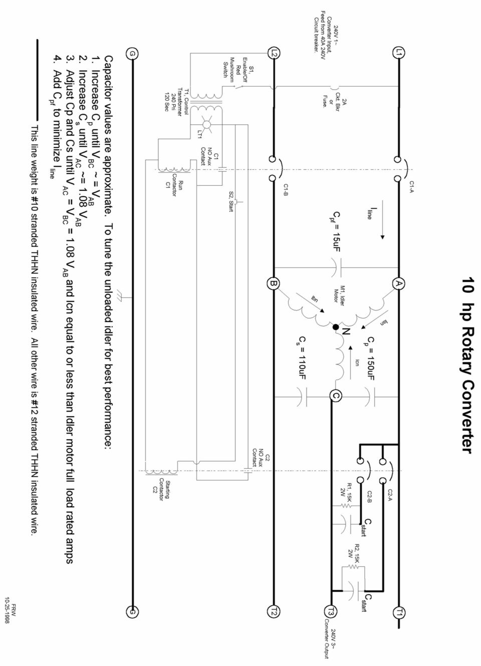
3 Typical data from an actual 10hp converter tune up session is shown in the tables below. This data is for a particular motor. Your measurements may vary from these, but the trends and general characteristics in response to changes should be the same. The goal is to tune up the unloaded converter so that the generated phases (Vac, Vbc) are equal to each other and 8% to 10% higher in voltage than the incoming line (Vab). Then Cpf is added to minimize the single phase line current for the unloaded converter. The concept is that the higher generated phases will be pulled down to at or maybe a bit below the incoming line voltage by the load, but will be much higher than they would be if no run caps were used. If the converter is tuned for voltage balance with the load attached, the open circuit voltage will be quite high, probably high enough to require 440V run caps instead of the 370V normally used. The process for tuning the converter is as follows: Wire up the converter except for the run capacitors (Cp, Cs, Cpf). Double check the wiring using an ohmmeter to verify that all is connected per the schematic. Start up the converter and take some voltage measurements (reference the schematic). They will probably look something like the measurements on the first line (Cp = Cs = Cpf = 0) of table I below. Trouble shoot and make corrections until this much of the converter is working properly. Turn off the converter and unplug from the wall between capacitance changes as required to perform the following steps: Add capacitance to gradually increase the value of Cp as shown in Table I below. Make measurements between each addition. Notice that Vbc is increasing faster than Vac. Stop when Vbc is about 1.03 times Vab. Add Cs in increments as shown in table I. Notice that Vac increases much more than Vbc. You may find you need to reduce Cs by a small amount. The goal is to end up with 1.08 Vab < Vac = Vbc < 1.10 Vab within a couple of volts or so. At the same time Icn should be less than the idler motor FLA rating. Table 1. Cp Cs Vab Vac Vbc

4 Now start adding Cs Cp Cs Vab Vac Vbc This looks just fine for voltage balance. On the schematic I sent, notice that L1 and L2 are the wires from the plug prior to any other components. The current should be close to the same in L1 and L2 (other than instrumentation error). Measure at that point and begin to add Cpf noting the line current in L1 after each addition. Add another capacitor and measure again. At some point, adding a capacitor will increase the current. If that was a big capacitor (say 50uF), remove it and add a smaller one (say 20uF). If the current decreases, leave that cap on and you are done. If it increases, take that cap off and you are done. The converter in this example ended up with a line current of 4.3A with Cpf = 15 uf. Incoming line current at L1 = 5.2A L2 = 6.1A before adding Cpf. After adding 15uf cap L1 = 4.3A. I believe that the line current could have been reduced further but the guy I was working with didn't want to fuss with it any more. Current measured at converter motor leads at Ian Ibn Icn unloaded idler hp lathe running 1000rpm no cutting Final values selected: Cp Cs Cpf Vab Vac Vbc unloaded idler with lathe at 1000rpm Il1 Ian Ibn Icn with lathe at 1000rpm
, remove it and add a smaller one (say 20uF). If the current decreases, leave that cap on and you are done. If it increases, take that cap off and you are done.")
5 Parts List: M1 T1 Cpf 10hp 17xx rpm 220/240V 3-ph motor Control transformer, use 4R390 or equivalent. The required fuse holder is integral with transformer. Use Grainger 1CT88 primary fuse. No secondary fuse is required. Represents capacitors wired in parallel to achieve required value. The capacitors used must be of the oil filled "run" capacitor type, 370 VAC minimum voltage rating. Connect the capacitors to the circuit using #10 wire and the appropriate crimp on connector. The connections to parallel them can be wire (see example below). Use Grainger 4X7nn series or equivalent. Cp Connection Example #10 50 uf 370 VAC 50 uf 370 VAC 50 uf 370 VAC #10 Cp Cs C1 C2 The primary run capacitor. This capacitor "must" be connected between the same two motor leads as the start capacitor. This capacitor is wired similarly to Cpf shown above but may be composed of 2, 3, 4 or more capacitors connected in parallel as required to achieve the performance specified on the schematic. Use Grainger 4X7nn series or equivalent. The secondary run capacitor. This capacitor is wired similarly to Cpf shown above but may be composed of 2, 3, 4 or more capacitors connected in parallel as required to achieve the performance specified on the schematic. Use Grainger 4X7nn series or equivalent. The motor Run Contactor. Use 5B109 or equivalent. This will have three sets of contacts. Use two for power connections, the other as the hold in connection. The starting contactor. Use 5B118 or equivalent. This will have three sets of contacts. Use two of them to connect the start capacitors, the other to operate the coil of the run contactor (C1).

6 S1 S2 LT1 Industrial SPST push button switch, momentary on. Use 5B453 with 5B536 contact block. Industrial SPST mushroom safety switch. Pull on, push off. Use 6B329 with 5B537 contacts. Industrial indicator light, 120V AC/DC. Use 5B455 or equivalent. R1, R2 Start Capacitor bleed resistor, two required. Use 6X181 or equivalent. Cstart Enclosure Start Capacitors, two required. Use 4X662 or equivalent. These parts all need to be mounted in an industrial type of enclosure. The enclosure was the most expensive part of the converter when I built mine. Use 3A907 or 3A908. Highly recommended procedure is to use plywood board same size as inside panel and do a trial assembly for bread board purposes using the plywood to mount the components. When it works fine, move it to the panel that mounts inside the enclosure listed above. Power cord. This unit should have at least an 8-3 SO power cord wired to a 40A 240V plug. Use a matching receptacle on the wall, feed from a 40A-circuit breaker/circuit with #8 wire minimum. Use the same type of cord to connect the idler motor to the control enclosure. Notes: Tool connections can be by hard wired into the converter or by using 3 phase 4 wire plugs on the end of 8-4 SO cords. The ground wire must be used to ground both the enclosure and the tool frames and must be totally separate from any other wires all the way back to the main entrance box. Mounting the idler motor on springs - several HD motor valve springs between the motor sub-base and the mounting frame can be used - will help to keep it quiet. Mount the control enclosure separate from the motor to reduce noise due to motor vibration resonating in the metal enclosure. FRW

Essential Electrical Concepts
 Essential Electrical Concepts Introduction Modern vehicles incorporate many electrical and electronic components and systems: Audio Lights Navigation Engine control Transmission control Braking and traction
3 Slot Payphone Controller
 5A2 3 Slot Payphone Controller The 3 Slot Payphone -- Part of American History Building a Coin Relay Controller Version S1BX Instruction Manual and Safety Precautions It is very important that for your
ECEN 1400, Introduction to Analog and Digital Electronics
 ECEN 1400, Introduction to Analog and Digital Electronics Lab 4: Power supply 1 INTRODUCTION This lab will span two lab periods. In this lab, you will create the power supply that transforms the AC wall
PS4-24 OWNERS MANUAL 24 VAC 90 WATT WALL MOUNTED CCTV POWER SUPPLY
 PS4-24 OWNERS MANUAL 24 VAC 90 WATT WALL MOUNTED CCTV POWER SUPPLY 7320 Ashcroft, Suite 104 Houston, Texas 77081 p: 713-772-1404 f: 713-772-7360 e: [email protected] www.juicegoose.com 06-06 CONGRATULATIONS
Parallel Circuits. Objectives After studying this chapter, you will be able to answer these questions: 1. How are electrical components connected
 This sample chapter is for review purposes only. Copyright The Goodheart-Willcox Co., Inc. All rights reserved. Electricity Objectives After studying this chapter, you will be able to answer these questions:.
GLOLAB Two Wire Stepper Motor Positioner
 Introduction A simple and inexpensive way to remotely rotate a display or object is with a positioner that uses a stepper motor to rotate it. The motor is driven by a circuit mounted near the motor and
Installation Manual Version 7.3 IMPORTANT:
 Installation Manual Version 7.3 IMPORTANT: READ ENTIRE MANUAL CAREFULLY, THIS PHASE CONVERTER MUST BE INSTALLED BY A INDUSTRIAL LICENSED ELECTRICIAN 230 VOLTS MODEL ONLY READ FIRST!!!!!! DANGER: HIGH VOLTAGE
INSTALLATION & SERVICE MANUAL. Display Panel
 INSTALLATION & SERVICE MANUAL Display Panel The PowerLine EMS TM is a specialized power distribution and energy management system intended to be used in recreational vehicles. The Control Module is housed
IDEAL INDUSTRIES, INC. TECHNICAL MANUAL MODELS: 61-763 61-765
 IDEAL INDUSTRIES, INC. TECHNICAL MANUAL MODELS: 61-763 61-765 The Service Information provides the following information: Precautions and safety information Specifications Performance test procedure Calibration
Single Phase Soft Starter
 Single Phase Soft Starter Installation & Operating Manual 6/02 Table of Contents Section 1 General Information................................................... 1 1 General Description................................................
 0150506194 C Limited 2nd through 5th Year Functional Parts Warranty During the 2nd through 5th year,haier will provide functional parts which prove to be defective due to workmanship
Manual Ranging MultiMeter
 Owner s Manual Manual Ranging MultiMeter Model 82345 CAUTION: Read, understand and follow Safety Rules and Operating Instructions in this manual before using this product.! Safety! Operation! Maintenance!
ELECTRIC HEATER COMPANY Operating and Maintenance Manual For Immersion Heating Elements
 ELECTRIC HEATER COMPANY Operating and Maintenance Manual For Immersion Heating Elements HUBBELL ELECTRIC HEATER COMPANY P.O. BOX 288 STRATFORD, CT 06615 PHONE: (203) 378-2659 FAX: (203) 378-3593 INTERNET:
6/14/02 Chapter 14: Use of Electrical Test Equipment 1/20
 USE OF ELECTRICAL TEST EQUIPMENT Test equipment is necessary for determining proper set-up, adjustment, operation, and maintenance of electrical systems and control panels. The following is a general procedure
Odyssey of the Mind Technology Fair. Simple Electronics
 Simple Electronics 1. Terms volts, amps, ohms, watts, positive, negative, AC, DC 2. Matching voltages a. Series vs. parallel 3. Battery capacity 4. Simple electronic circuit light bulb 5. Chose the right
An Easy to Build and Operate Induction Generator
 An Easy to Build and Operate Induction Generator Believe it or not, nearly everyone you know has at least one induction generator and probably more That's right! You say that is impossible... well, read
A4 Air Conditioning Control Circuit Troubleshooting Rev 7, 6/18/2009
 A4 Air Conditioning Control Circuit Troubleshooting Rev 7, 6/18/2009 ** This guide is for Manual Air Conditioning (as opposed to Climatronic A/C or Climatic A/C), with two 2-speed fans on Volkswagen A4's
LG Air Conditioning Multi F(DX) Fault Codes Sheet. Multi Split Units
 Fault Codes Sheet. Multi Split Units") Multi Split Units If there is a fault on any LG Multi unit, an Error mark is indicated on the display window of the indoor unit, wired-remote controller, and LED s of outdoor unit control board. A two
Multi Split Units If there is a fault on any LG Multi unit, an Error mark is indicated on the display window of the indoor unit, wired-remote controller, and LED s of outdoor unit control board. A two
Resistance, Ohm s Law, and the Temperature of a Light Bulb Filament
 Resistance, Ohm s Law, and the Temperature of a Light Bulb Filament Name Partner Date Introduction Carbon resistors are the kind typically used in wiring circuits. They are made from a small cylinder of
AutoRanging Digital MultiMeter
 Owner's Manual AutoRanging Digital MultiMeter Model No. 82139 CAUTION: Read, understand and follow Safety Rules and Operating Instructions in this manual before using this product. Safety Operation Maintenance
Objectives: Part 1: Build a simple power supply. CS99S Laboratory 1
 CS99S Laboratory 1 Objectives: 1. Become familiar with the breadboard 2. Build a logic power supply 3. Use switches to make 1s and 0s 4. Use LEDs to observe 1s and 0s 5. Make a simple oscillator 6. Use
Building an Auto-Start Rotary Three Phase Converter. by: Matt Isserstedt
 Building an Auto-Start Rotary Three Phase Converter by: Matt Isserstedt Disclaimer: Electrical wiring is inherently dangerous. No warranties are issued or implied about the safety or success of this system.
Allen-Bradley 1397 400-600HP AC Line Filter Kit
 Installation Instructions IN Allen-Bradley 1397 400-600HP AC Line Filter Kit Cat. Nos. 1397-LF600 What This Option Provides What This Kit Contains This option is intended to be applied when the primary
Transformer circuit calculations
 Transformer circuit calculations This worksheet and all related files are licensed under the Creative Commons Attribution License, version 1.0. To view a copy of this license, visit http://creativecommons.org/licenses/by/1.0/,
Glolab Talking Phone Dial Monitor
 Introduction The detects the tones generated when numbers are dialed on your touch tone telephone and speaks the numbers that were dialed. This verifies that you dialed the correct number and is especially
Wires & Connections Component Circuit Symbol Function of Component. Power Supplies Component Circuit Symbol Function of Component
 Lista Dei Simboli Dei Circuiti Per i Componenti Elettronici Wires & Connections Wire Wires joined Wires not joined To pass current very easily from one part of a circuit to another. A 'blob' should be
CONSTRUCTING A VARIABLE POWER SUPPLY UNIT
 CONSTRUCTING A VARIABLE POWER SUPPLY UNIT Building a power supply is a good way to put into practice many of the ideas we have been studying about electrical power so far. Most often, power supplies are
ARCO Electric Products Installation and Maintenance Manual Low Voltage Automatic Power Factor Correction Capacitor Systems 2013
 ARCO Electric Products Installation and Maintenance Manual Low Voltage Automatic Power Factor Correction Capacitor Systems 2013 READ CAREFULLY These instructions are intended to cover good practices in
E2 Series Electric Furnaces
 E2 Series Electric Furnaces Service Manual Table of Contents Electrical Requirements... 10 Codes, Specifications Requirements... 10 Connection Supply Service Wires... 10 Furnace Sequence of Operation...
Instruction Manual. 2in1 LAN Tester & Multimeter. Model: LA-1011
 Instruction Manual 2in1 LAN Tester & Multimeter Model: LA-1011 1 Contents Introduction... Features... Safety Precautions.. Meter Description... Electrical Specification... Operation.. AutoRanging Multimeter.
The Charging System. Section 5. Charging System. Charging System. The charging system has two essential functions:
 The Charging System Charging System The charging system has two essential functions: Generate electrical power to run the vehicle s electrical systems Generate current to recharge the vehicle s battery
Expat Audio Uber Power Supply... 2 Introduction... 2 Revision Control & Edits... 2 The Schematic... 3 Calculating the value of R1,R2 and R3...
 Expat Audio Uber Power Supply... 2 Introduction... 2 Revision Control & Edits... 2 The Schematic... 3 Calculating the value of R1,R2 and R3... 4 Assembling the board... 5 Connecting in your system... 7
Service manual. Website: www.andico.com.au CAUTION - BEFORE SERVICING THE UNIT, READ THE SAFETY - PRECAUTIONS IN THIS MANUAL.
 Website: www.andico.com.au Service manual CAUTION - BEFORE SERVICING THE UNIT, READ THE SAFETY - PRECAUTIONS IN THIS MANUAL. - ONLY FOR AUTHORISED SERVICE PERSONNEL. MODELS: MPK1-09CR-QB8 MPK1-12ER-QB6
TROUBLESHOOTING GUIDE
 TROUBLESHOOTING GUIDE LESTRONIC II BATTERY CHARGER FOR MOTIVE POWER BATTERIES PLEASE SAVE THESE IMPORTANT SAFETY AND OPERATING INSTRUCTIONS For correct operation of the equipment, it is important to read
SUBJECT: How to wire a motor starter Number: AN-MC-004 Date Issued: 2/08/2005 Revision: Original
 SUBJECT: How to wire a motor starter Number: AN-MC-004 Date Issued: 2/08/2005 Revision: Original A motor starter is a combination of devices to allow an induction motor to start, run and stop according
ETZGAR CONVEYOR COMPANY Controls Section v12.05
 Section 7 Controls Page Description 7-1 Controls Index 7-2 Motor Data, Enclosure Rating and Abbreviations 7-3 Controls Safety Guidelines 7-4 Fixed Speed Controls Packages 7-5 Three Phase AC Variable Speed
Product Guide AC Voltage Control Devices. Guide Guide. Popular Variable Transformers and AC Power Supplies. www.stacoenergy.com
 Popular Variable Transformers and AC Power Supplies Product Guide AC Voltage Control Devices Guide Guide Your Tailored Power Solutions Provider TM Staco Energy Products Co. has been a leading manufacturer
Lab E1: Introduction to Circuits
 E1.1 Lab E1: Introduction to Circuits The purpose of the this lab is to introduce you to some basic instrumentation used in electrical circuits. You will learn to use a DC power supply, a digital multimeter
Battery Chargers. Revised 8/00 Form Number 56041170 FORM NO. 56041170 / BATTERY CHARGER SERVICE MANUAL / PARTS LIST - 45
 Battery Chargers SERVICE MANUAL / PARTS LIST AUTOMATIC Advance MODELS 0980, 098, 797, 8809, 90, 880, 880, 099, 08,, 09788, 098, 7, 097, 70, 790, 889 Lester MODELS 007,, 8, 8, 89, 80, 9, 00, 00, 008 MANUAL
Whale 3. User Manual and Installation Guide. DC Servo drive. Contents. 1. Safety, policy and warranty. 1.1. Safety notes. 1.2. Policy. 1.3. Warranty.
 Whale 3 DC Servo drive User Manual and Installation Guide Contents 1. Safety, policy and warranty. 1.1. Safety notes. 1.2. Policy. 1.3. Warranty. 2. Electric specifications. 2.1.Operation ranges. 3. Connections
SERVICE MANUAL 12VDC WALL THERMOSTAT AIR CONDITIONING SYSTEMS ROOFTOP UNITS ONLY
 SERVICE MANUAL 12VDC WALL THERMOSTAT AIR CONDITIONING SYSTEMS ROOFTOP UNITS ONLY! WARNING - SHOCK HAZARD! TO PREVENT THE POSSIBILITY OF SEVERE PERSONAL INJURY, DEATH, OR EQUIPMENT DAMAGE DUE TO ELECTRICAL
Introduction. Safety Guidelines. Part Numbers. Operation and Maintenance Manual. Operation and Maintenance Manual
 Operation and Maintenance Manual Introduction Read all instructions thoroughly. Installation of the OilTector must comply with all Federal, State and Local Codes, Regulations and Practices. The OilTector
What is a multimeter?
 What is a multimeter? A multimeter is a devise used to measure voltage, resistance and current in electronics & electrical equipment It is also used to test continuity between to 2 points to verify if
PHYSICS 111 LABORATORY Experiment #3 Current, Voltage and Resistance in Series and Parallel Circuits
 PHYSCS 111 LABORATORY Experiment #3 Current, Voltage and Resistance in Series and Parallel Circuits This experiment is designed to investigate the relationship between current and potential in simple series
73 Chevy C10 Ammeter to Volt Gauge Conversion Mark and Michael Olson 2013 Rev 1.0
 73 Chevy C10 Ammeter to Volt Conversion Mark and Michael Olson 2013 Rev 1.0 The ammeter in my son s 73 Chevy C10 did not work, so we decided to convert it to a more modern volt gauge. We made a number
Product Guide. Low voltage grounding system. Answers for industry.
 Product Guide Low voltage grounding system Answers for industry. Advanced switchgear solutions for process industries In today s high-tech manufacturing world, profitability can be greatly impacted by
User Guide. Model 380260 Insulation Tester / Megohmmeter
 User Guide Model 380260 Insulation Tester / Megohmmeter Introduction Congratulations on your purchase of Extech s Insulation Tester/Megohmmeter. The Model 380260 provides three test ranges plus continuity
Fan Coil EC Motor Control
 Fan Coil EC Motor Control G3 PWM BARD The Enviro-Tec Generation 3 PWM (G3 PWM) board provides a pulse-width modulated (PWM) signal to the EC motor to control fan speed. The board is factory programmed
Companion Service Guide
 Companion Service Guide This Service Guide contains: Troubleshooting Replacement Instructions Contact Information Golden Technologies 401 Bridge Street Old Forge, PA 18518 Toll-free: 800-624-6374 Fax:
Chapter 13: Electric Circuits
 Chapter 13: Electric Circuits 1. A household circuit rated at 120 Volts is protected by a fuse rated at 15 amps. What is the maximum number of 100 watt light bulbs which can be lit simultaneously in parallel
Battery Charger For Nickel Cadmium and Nickel-Metal Hydride Rechargeable Batteries Model PSN Series
 Battery Charger For Nickel Cadmium and Nickel-Metal Hydride Rechargeable Batteries Model PSN Series Operating Instructions WARNING CONCERNING THE REMOVAL OF COVER: CAUTION: TO PREVENT THE RISK OF ELECTRIC
AP Physics Electricity and Magnetism #4 Electrical Circuits, Kirchoff s Rules
 Name Period AP Physics Electricity and Magnetism #4 Electrical Circuits, Kirchoff s Rules Dr. Campbell 1. Four 240 Ω light bulbs are connected in series. What is the total resistance of the circuit? What
ABR Brake Rectifier Instruction Manual
 ABR Brake Rectifier Instruction Manual Part Number: 552074 Copyright 2012 Magnetek 1. Preface and Safety All rights reserved. This notice applies to all copyrighted materials included with this product,
CHAPTER 11: Flip Flops
 CHAPTER 11: Flip Flops In this chapter, you will be building the part of the circuit that controls the command sequencing. The required circuit must operate the counter and the memory chip. When the teach
Oil and Coolant Circulating Heating System. Model - OCSM
 Oil and Coolant Circulating Heating System Model - OCSM Installation & Operation Manual 216280-000 REV 2 Identifying Your System The HOTSTART heating system is designed to heat fluids for use in marine
Generator Transfer Switch Model # HTS15-AUTO
 Generator Transfer Switch Model # HTS15-AUTO Congratulations on your purchase of our Single Circuit Generator Transfer Switch, We hope this meets and exceeds your expectations. If at anytime you have any
Multimeter measurements on variable frequency drives using the new Fluke 289 DMM
 Multimeter measurements on variable frequency drives using the new Fluke 289 DMM Application Note Editor s note: For similar instructions using the Fluke 87V DMM, reference Fluke article 12345. In the
Experiment #5, Series and Parallel Circuits, Kirchhoff s Laws
 Physics 182 Summer 2013 Experiment #5 1 Experiment #5, Series and Parallel Circuits, Kirchhoff s Laws 1 Purpose Our purpose is to explore and validate Kirchhoff s laws as a way to better understanding
Line Reactors and AC Drives
 Line Reactors and AC Drives Rockwell Automation Mequon Wisconsin Quite often, line and load reactors are installed on AC drives without a solid understanding of why or what the positive and negative consequences
TROUBLESHOOTING, REPAIR, AND REPLACEMENT GUIDE FOR MODEL #19300 BATTERY CHARGER PLEASE SAVE THESE IMPORTANT SAFETY INSTRUCTIONS
 *35827* TROUBLESHOOTING, REPAIR, AND REPLACEMENT GUIDE FOR MODEL #19300 BATTERY CHARGER PLEASE SAVE THESE IMPORTANT SAFETY INSTRUCTIONS For correct operation of the equipment, it is important to read and
ECOSMART TROUBLE SHOOTING GUIDE MODELS ECO18-ECO27
 ECOSMART TROUBLE SHOOTING GUIDE MODELS ECO18-ECO27 THIS STEP BY STEP TROUBLE SHOOTING GUIDE IS DESIGNED FOR THE INSTALLER IF ANY ISSUES ARISE WITH TANKLESS WATER HEATER. YOU CAN ALSO VIEW A TROUBLE SHOOTING
Lab 3 - DC Circuits and Ohm s Law
 Lab 3 DC Circuits and Ohm s Law L3-1 Name Date Partners Lab 3 - DC Circuits and Ohm s Law OBJECTIES To learn to apply the concept of potential difference (voltage) to explain the action of a battery in
VOLUME AND TONE CONTROL - PREAMPLIFIER K8084
 H8084IP-1 VOLUME AND TONE CONTROL - PREAMPLIFIER K8084 When using one of our amplifiers (big or small), you always need a volume control and preferably also a tone control Features & specifications When
Application Note. Troubleshooting Communications
 ANX Application Note Troubleshooting Communications This document is a guide for basic troubleshooting of UPB communication issues. There are two things that can disturb UPB communications: noise and attenuation.
Windshield Wiper Motors
 Windshield Wiper Motors Originally posted by Dan Masters, [email protected] Also see http://www.advanceautowire.com/ WIPER OPERATION: There are three major components to a wiper motor: Motor Rotary to linear
Troubleshooting Guide, Freedom and Fleet Power Inverter/Chargers
 Technical Note Freedom/Fleet Power 512-0084-01-01 Rev 1 Troubleshooting Guide, Freedom and Fleet Power Inverter/Chargers Overview This document is a guide for troubleshooting inverters, battery chargers,
Video Camera Installation Guide
 Video Camera Installation Guide The intent of this guide is to provide the information needed to complete or modify a video camera installation to avoid lightning and induced power surge damage. This guide
9.23 Treadmill. 9.23 Treadmill
 9.23 Treadmill Warning: This service manual is for use by Precor trained service providers only. If you are not a Precor Trained Servicer, you must not attempt to service any Precor Product; Call your
People s Physics Book
 The Big Ideas: The name electric current is given to the phenomenon that occurs when an electric field moves down a wire at close to the speed of light. Voltage is the electrical energy density (energy
AE21-1319 R6 December 2013. Digital Capacity Control for Copeland Scroll Refrigeration Compressors AE21-1319 R6
 AE21-1319 R6 December 2013 Digital Capacity Control for Copeland Scroll Refrigeration Compressors TABLE OF CONTENTS Section Page Section Page Safety Safety Instructions...2 Safety Icon Explanation...2
OPL BASIC. Dosing System for Professional Laundry machines. Contents
 OPL BASIC Dosing System for Professional Laundry machines Contents 1 Getting Started. Page 2 2 Installation. Page 4 3 Set Up & Operation. Page 8 4 Maintenance & Accessories. Page 10 5 Troubleshooting Page
..OR How To Protect your 3-Phase Equipment Investment with 3-Phase Monitors from Time Mark...
 ..OR How To Protect your 3-Phase Equipment Investment with 3-Phase Monitors from Time Mark... TIME MARK CORPORATION 11440 EAST PINE STREET TULSA, OK 74116 USA tel 918 438-1220 fax 918 437-7584 www.time-mark.com
Student Exploration: Circuits
 Name: Date: Student Exploration: Circuits Vocabulary: ammeter, circuit, current, ohmmeter, Ohm s law, parallel circuit, resistance, resistor, series circuit, voltage Prior Knowledge Questions (Do these
RADIANT PLASMA 4700 Plasma Spark Generator
 RADIANT PLASMA 4700 Plasma Spark Generator Installation Guide / User Manual A S P A R K O F F R E S H A I R Aquapulser.com Contents 1 Introduction 2 1.1 About the Product....................................
SECTION 4 ELECTRIC MOTORS UNIT 17: TYPES OF ELECTRIC MOTORS
 SECTION 4 ELECTRIC MOTORS UNIT 17: TYPES OF ELECTRIC MOTORS UNIT OBJECTIVES After studying this unit, the reader should be able to Describe the different types of open single-phase motors used to drive
Owner s Manual & Safety Instructions
 Owner s Manual & Safety Instructions Save This Manual Keep this manual for the safety warnings and precautions, assembly, operating, inspection, maintenance and cleaning procedures. Write the product s
AFE424 SERVICE PARTS
 This is the parts list for the AFE. When looking up part numbers, always check the complete model and serial numbers to be certain of ordering the correct parts. The Air Cooled model has also been manufactured
Measuring Electric Phenomena: the Ammeter and Voltmeter
 Measuring Electric Phenomena: the Ammeter and Voltmeter 1 Objectives 1. To understand the use and operation of the Ammeter and Voltmeter in a simple direct current circuit, and 2. To verify Ohm s Law for
CSA Z32 TESTING GUIDELINE AND PROCEDURES
 PO Box 20020 Red Deer, AB T4N 6X5 Phone: 403.986.2939 Web: www.908eng.com July 9, 2012 CSA Z32 TESTING GUIDELINE AND PROCEDURES This document is intended to outline the various tests, procedures and preparations
Chapter 5. Components, Symbols, and Circuitry of Air-Conditioning Wiring Diagrams
 Chapter 5 Components, Symbols, and Circuitry of Air-Conditioning Wiring Diagrams Objectives Upon completion of this course, you will be able to: Explain what electrical loads are and their general purpose
Section B: Electricity
 Section B: Electricity We use mains electricity, supplied by power stations, for all kinds of appliances in our homes, so it is very important to know how to use it safely. In this chapter you will learn
Electric Panel Pump Control System. Operation, Maintenance and Installation Manual
 Manual No. 5EP-OM1-1 Electric Panel Pump Control System Operation, Maintenance and Installation Manual INTRODUCTION... 1 RECEIVING AND STORAGE... 1 DESCRIPTION OF OPERATION... 1 INSTALLATION... 2 SEQUENCE
CHAPTER 4 UTILITY SYSTEMS ELECTRICAL. Utility Systems Electrical. Main Panel
 CHAPTER 4 UTILITY SYSTEMS ELECTRICAL Utility Systems Electrical The electrical supply to your home begins outside, where you will see either an overhead feed and piping down the side of your home or (if
CAPACITOR AND APFC SYSTEM SERVICE MANUAL
 CAPACITOR AND APFC SYSTEM INSTALLATION & TROUBLE SHOOTING 1. POWER FACTOR IS NOT IMPROVING 1. Please check if required kvar of capacitors are installed. 2. Check the type of capacitor installed is suitable
Table of Contents. The Basics of Electricity 2. Using a Digital Multimeter 4. Testing Voltage 8. Testing Current 10. Testing Resistance 12
 Table of Contents The Basics of Electricity 2 Using a Digital Multimeter 4 IDEAL Digital Multimeters An Introduction The Basics of Digital Multimeters is designed to give you a fundamental knowledge of
Installation Instructions
 Installation Instructions For Use with PXPV230, PXPV265, PXPD230, and PXPD265 models Attention! - Please read these instructions completely before attempting installation. Always unplug the power supply
EVANS ELECTRONIC TEMPERATURE CONTROL TROUBLESHOOTING GUIDE for systems equipped with electric coolant valve and external PC board.
 EVANS ELECTRONIC TEMPERATURE CONTROL TROUBLESHOOTING GUIDE for systems equipped with electric coolant valve and external PC board. This Troubleshooting Guide covers the electric coolant valve and control
What Is Regeneration?
 What Is Regeneration? Braking / Regeneration Manual Regeneration Overview Revision 1.0 When the rotor of an induction motor turns slower than the speed set by the applied frequency, the motor is transforming
ALL PURPOSE CNC/HEAVY DUTY
 ALL PURPOSE CNC/HEAVY DUTY ROTARY PHASE CONVERTERS 240 VOLT SERIES MODELS: AR AD ADX OPERATION & INSTALLATION MANUAL American Rotary, LLC www.americanrotary.com 2014 DANGER: HIGH VOLTAGE Electric shock
Section M POWER LIFTS
 Section M POWER LIFTS December 2009 1M Index 1. 53-520244-000 Poly V Idler Assembly 2. 53-520205-000 N.A. Mounting Bracket 3. 53-520212-000 Cable Assembly 4. 53-600149-000 Wire Harness Assembly 5. 53-860322-010
Chapter 7 Direct-Current Circuits
 Chapter 7 Direct-Current Circuits 7. Introduction...7-7. Electromotive Force...7-3 7.3 Resistors in Series and in Parallel...7-5 7.4 Kirchhoff s Circuit Rules...7-7 7.5 Voltage-Current Measurements...7-9
Tips for connecting 24-volt power
 Digital Designer s Guide Application NoteAN0604D Revision B Tips for connecting 24-volt power This application note covers choosing a transformer and connecting 24 volt AC power to a KMC Controls DDC controller.
Safety, Operation and Maintenance Manual with Parts List
 Safety, Operation and Maintenance Manual with Parts List 20-Gallon Wet/Dry Vac Important Information and Safety Instructions PLEASE READ BEFORE USE! # 961130020 9/10-Rev 1 20-Gallon Wet/Dray Vac TABLE
http://waterheatertimer.org/how-to-troubleshoot-gas-water-heater.html
 http://waterheatertimer.org/how-to-troubleshoot-gas-water-heater.html TECHNICAL SERVICE DEPARTMENT Effective October 2007, we transitioned to the White Rodgers (Intelli-Vent TM )Thermostat Control for
SAFETY PRECAUTIONS AND INSTRUCTIONS FOR USE OF TECHNICAL INFORMATION
 SAFETY PRECAUTIONS AND INSTRUCTIONS FOR USE OF TECHNICAL INFORMATION Please read and understand the product instruction manual before installing, servicing or operating Yaskawa products. Technical content
The Child Reminder System Installation Manual
 The Child Reminder System Installation Manual Revised June, 2006 Detailed installation information can be found at www.childreminder.com. Get through your installation quickly and easily by calling 1-888-330-6786
Redesigned by Laurier Gendron (Aug 2006 ) Download this project in PDF. Horn circuit. Train Circuitry
 Download this project in PDF. Horn circuit. Train Circuitry") Redesigned by Laurier Gendron (Aug 2006 ) Download this project in PDF Train Circuitry Horn circuit New Design After many comments by interested hobbyists not being able to obtain parts like the LM566
Redesigned by Laurier Gendron (Aug 2006 ) Download this project in PDF Train Circuitry Horn circuit New Design After many comments by interested hobbyists not being able to obtain parts like the LM566
GROUND DETECTION CIRCUITS FOR STATIONARY APPLICATIONS (IN PLAIN DOWN TO EARTH LANGUAGE)
") GROUND DETECTION CIRCUITS FOR STATIONARY APPLICATIONS (IN PLAIN DOWN TO EARTH LANGUAGE) Matthew Theriault Designer Hindle Power Inc. Easton, PA SCOPE AND PURPOSE OF THE PAPER Why do we bother to monitor
GROUND DETECTION CIRCUITS FOR STATIONARY APPLICATIONS (IN PLAIN DOWN TO EARTH LANGUAGE) Matthew Theriault Designer Hindle Power Inc. Easton, PA SCOPE AND PURPOSE OF THE PAPER Why do we bother to monitor
Automatic taper of charge rate for superior battery life through good equalization of cells and low water use rate.
 *00151* FEATURES Automatic taper of charge rate for superior battery life through good equalization of cells and low water use rate. Silicon diodes with inherent surge protection operated at a conservative