AVR042: AVR Hardware Design Considerations. Introduction. Features. 8-bit AVR Microcontroller APPLICATION NOTE
|
|
|
- Alexis Snow
- 9 years ago
- Views:
Transcription
1 8-bit AVR Microcontroller AVR042: AVR Hardware Design Considerations APPLICATION NOTE Introduction This application note provides basic guidelines to be followed while designing hardware using Atmel AVR microcontrollers. Some of the known problems faced in real-time designs have been addressed by providing possible solutions and work-arounds to resolve them. The scope of this application note is to provide an introduction to potential design problems rather than being an exhaustive documentation on designing applications using the AVR microcontrollers. This document is a collection of information from existing Atmel AVR documents along with some additional information that were not documented earlier. Note: Read the application note AVR040 - EMC Design Considerations before starting a new design, especially if the design is expected to meet the requirements of the EMC directive or any other similar directives in countries outside Europe. Features Guidelines for providing robust analog and digital power supply Connection of RESET line Interfacing Programmers/Debuggers to AVR Using external Crystal or Ceramic Resonator Oscillators

2 Table of Contents Introduction...1 Features Abbreviations Power Supply Digital Supply Analog Supply Noise Implications Connection of RESET Pin on AVRs External RESET Switch Connecting Programmer / Debugger Lines SPI Programming Interface JTAG Interface PDI Interface TPI Interface UPDI Interface Using Crystal and Ceramic Resonators Selecting the Clock Source in the AVR About Crystals and Ceramic Resonators Recommended Capacitor Values Unbalanced External Capacitors RTC Crystals PCB Layout Example Layout of ATxmega32A4 and ATmega324PB device Revision History

3 1. Abbreviations ADC AREF CPU DC DIP EEPROM or E 2 PROM EMC ESD GND HVPP Hz I/O IDE ISP KHz LED MCU MHz MISO MOSI PCB PDI RC Filter RST SPI TPI UPDI V CC XTAL Analog to Digital Converter Analog Reference Voltage Central Processing Unit Direct Current Dual In-line Package Electrically Erasable Programmable Read-Only Memory Electromagnetic Compatibility Electrostatic Discharge Ground High-Voltage/Parallel Programming Hertz Input and Output Integrated Development Environment In-System Programming KiloHertz Light Emitting Diode Microcontroller Unit MegaHertz Master In Slave Out Master Out Slave In Printed Circuit Board Program and Debug Interface Resistor-Capacitor Filter Reset Serial Peripheral Interface Tiny Programming Interface Unified Program and Debug Interface Supply Voltage Crystal Oscillator 3

4 2. Power Supply Power Supply is the most critical part of any hardware design, which directly affects the performance of the system. Two important aspects to be considered while designing a power supply for the discrete/ digital elements of an Atmel AVR are ESD Protection and Noise Emission. These aspects are covered in-detail the AVR040 application note and hence only a short summary is included in this document Digital Supply Most AVR microcontrollers operate over a wide voltage range and draws only a few milliamps of supply current. This may give an impression that power supply is not critical. But as with any digital circuits, the supply current is an average value. The current is drawn in very short spikes on the clock edges. If I/O lines are switching, the spikes will be even higher. If all eight I/O lines of an I/O port changes value, simultaneously, the current pulses on the power supply lines can be several hundred ma. If the I/O lines are not loaded, the pulse will last for only a few nanoseconds. Such a current spike cannot be delivered over long power supply lines; the main source is (or should be) the decoupling capacitor. Figure 2-1. Incorrect Decoupling V CC Power Plane I = MCU C High Curre nt Loop V CC Out V = GND Ground Plane Figure 2-1 shows an example of insufficient decoupling. The capacitor is placed too far away from the microcontroller, creating a larger high current loop. The power and ground planes are parts of the high current loop. As a result of this, noise is spread more easily to other devices on the board, and radiated emission from the board is increased even further. The whole ground plane will act as an antenna for the noise, instead of only the high current loop. This will be the case when the power and ground pins are connected directly to the planes (typical for hole-mounted components) and the decoupling capacitor is connected the same way. This is often seen in boards with surface-mount components where the integrated circuits are placed on one side of the board and the decoupling capacitors are placed on the other side. Figure 2-2 shows a better placement of the capacitor. The lines that are part of the high current loop are not part of the power or ground planes. This is important, as the power and ground planes otherwise will spread a lot of noise. Further, the figure shows another improvement in the decoupling. A series ferrite bead is inserted to reduce the switching noise on the power plane. The series impedance of the ferrite bead must be low enough to ensure that there is no significant drop in the DC voltage. 4

5 Figure 2-2. Decoupling with Series Inductor V CC I = Power Plane L I = Ferrite Bead C High Current Loop V CC MCU Out V = GND Ground Plane In Atmel AVR devices where power and ground lines are placed close together there will be better decoupling than the devices with industry standard pin-out. In industry standard pin-out, the power and ground pins are placed in opposite corners of the DIP package. This disadvantage can be overcome by placing decoupling capacitors very close to the die. For devices with multiple pairs of power and ground pins, it is essential that there is a decoupling capacitor for every pair of pins. The main power supply should also have a tantalum or ceramic capacitor to stabilize it Analog Supply The AVR devices that have a built-in ADC that have a separate analog supply voltage pin, A Vcc. This separate voltage supply ensures that the analog circuits are less prone to the digital noise originating from the switching of the digital circuits. To improve the accuracy of the ADC, the analog supply voltage must be decoupled separately, similar to the digital supply voltage. AREF must also be decoupled. The typical value for the capacitor is 100nF. If a separate analog ground (AGND) is present, the analog ground should be separated from the digital ground so that the analog and digital grounds are only connected at a single point (at the power supply GND) Noise Implications When AVR devices are operate at CPU speeds around 2MHz with varying supply voltage and/or temperature conditions, it is affected by noise issues. These noise related issues are prominent after power-up, wake-up, or after any changes to the clock prescaler. To resolve such issues, select either lower or higher CPU speeds and to use high quality low-noise digital and analog power supply. 5

6 3. Connection of RESET Pin on AVRs The RESET pin on the AVR is active LOW, and setting the pin LOW externally will reset of the AVR. The RESET has two purposes: 1. To release all the lines by tri-stating all pins (except XTAL pins), initialize all I/O registers and set program counter to zero. 2. To enter programming mode (for some parts, the PEN line is also used to enter programming mode). It is also possible to enter High-Voltage/Parallel Programming (HVPP) mode by drawing the RESET pin very high (11.5V 12.5V). Refer to the respective device datasheet for more specific information about RESET pin and its functionality. The reset line has an internal pull-up resistor. But if the environment is noisy, it can be insufficient and reset may occur sporadically. Refer to the device datasheet for the value of pull-up resistor that must be used for specific devices. Connecting the RESET such that it is possible to enter both high-voltage programming and ordinary low level reset can be achieved by using a pull-up resistor to the RESET line. This pull-up resistor avoids any unindented low signal that will trigger a RESET. Theoretically, the pull-up resistor can be of any value, but if the Atmel AVR should be programmed using an external programmer, the pull-up should not be in such a high state that the programmer is not able to activate RESET by drawing the RESET line low. The recommended pull-up resistor value is 4.7kΩ or larger when using STK600 for programming. For DebugWIRE to function properly, the pull-up must not be lesser than 10kΩ. To protect the RESET line from further noise, connect a capacitor from the RESET pin to ground. This is not directly required since the AVR internally have a low-pass filter to eliminate spikes and noise that could cause reset. Useing an extra capacitor is an additional protection. However, such extra capacitor cannot be used when DebugWIRE or PDI is used. ESD protection diode is not provided internally from RESET to Vcc in order to allow HVPP. If HVPP is not used, it is recommended to add an ESD protection diode externally from RESET to Vcc. Alternatively, a Zener diode can be used to limit the RESET voltage relative to GND. A Zener diode is highly recommended in noisy environments. The components should be located physically close to the RESET pin of the AVR. Recommended circuit on RESET line is shown in the following circuit diagram. Figure 3-1. Recommended Reset Pin Connection V CC R 4.7kΩ External Reset D Reset MCU Reset Module C 100nF GND Note: The values of resistor R and capacitor C are typical values used for the RESET pin. For specific design requirements of an application, these values must be changed accordingly. 6
 mode by drawing the RESET pin very high (11.5V 12.5V).")
7 3.1. External RESET Switch If an external switch is connected to the RESET pin, it is important to add a series resistance. Whenever the switch is pressed, it will short the capacitor and the current (I) through the switch can have high peak values. This causes the switch to bounce and generate steep spikes in 2ms - 10ms (t) periods until the capacitor is discharged. The PCB tracks and the switch metal introduces a small inductance (L) and the high current through these tracks can generate high voltages up to V L = L * di / dt. This spike voltage V L is most likely outside the specification of the RESET pin. By adding a series resistor between the switch and the capacitor, the peak currents generated will be significantly low and it will not be large enough to generate high voltages at the RESET pin. An example connection is shown in the following diagram. Figure 3-2. Switch Connection for Reset Pin 7
 and the high current through these tracks can generate high voltages up to V L = L * di / dt.")
 is a programming interface used for programming the Flash, EEPROM, Lock-bits, and Fuse-bits in almost all AVRs.")
8 4. Connecting Programmer / Debugger Lines Atmel AVR microcontrollers feature one or more interfaces for Programming or Debugging. In-System Programming (ISP) is a programming interface used for programming the Flash, EEPROM, Lock-bits, and Fuse-bits in almost all AVRs. This feature makes it possible to program the AVR in the last stage of production of a target application board, reprogram if SW bugs are identified late in the process, or even update the AVR in the field, if required. Some ISP interfaces may also be used for on-chip debugging. It is therefore recommended to design the target application board such that the ISP connectors are easily accessible. Note: Refer the respective device datasheet to know the programming / debugging interfaces support by the device SPI Programming Interface On devices that use a Serial Peripheral Interface (SPI) for ISP, these lines are usually located on the same pins as regular SPI, or else on pins that can be used for other purposes. Refer the device data sheet to determine the pins are used for ISP. Two standard SPI connectors are provided by the Atmel ISP programmers; a 6-pin and a 10-pin connector. In addition to the data lines (MOSI and MISO) and the bus clock (SCK), target voltage VTG, GND, and RESET (RST) are also provided through these connectors. Figure 4-1. Connections for 6/10 Pin ISP Headers A few ISP programmers are powered by the target power supply. In this way they easily adapt to the correct voltage level of the target board. Other ISP programmers, such as Atmel STK600 can alternatively power the target board via the VTG line. In such a case, it is important that the power supply on the target is not switched on. Note: Refer the respective programmer user guide for more information about the capabilities and physical interface Shared Use of SPI Programming Lines If additional devices are connected to the ISP lines, the programmer must be protected from any device that may try to drive the lines, other than the AVR. This is important with the SPI bus, as it is similar to the ISP interface. Applying series resistors on the SPI lines, as depicted in Connecting the SPI Lines to the ISP Interface, is the easiest way to achieve this. Typically, the resistor value R can be of 330Ω (1). 8

 of 3.3V.")
9 Figure 4-2. Connecting the SPI Lines to the ISP Interface SCK MOSI SCK MISO MOSI MISO RST R R R SPI Bus SCK MOSI MISO Reset AVR Note: 1. These typical values are used to limit the input current to 10mA for a supply voltage (V CC ) of 3.3V. It may vary depending on the programmer/debugger used and requirements of specific hardware design. 2. The AVR will never drive the SPI lines in a programming situation. Since the AVR is held in RESET to enter programming mode, which puts all AVR pins to tri-states. In a single application, multiple Atmel AVR devices can share the same ISP interface. This enables to program all the devices through a minimal interface. However, if there are no special design considerations, then all the AVR devices will respond to the ISP instructions. The SPI clock lines should be seperately provided (can be gated using jumpers or DIP switches) so that only one of the AVR devices recieves SPI clock at a time. Other SPI lines (MOSI & MISO) can be shared. This method ensures that AVRs are seperated from the programmer by the same protection resistors, since they are all held in RESET while the ISP reset line is activated. The ISP clock can be gated using jumpers or DIP switches. An alternate solution is to use multiple ISP interfaces, one for each device, all protected seperately with series resistors JTAG Interface Few devices have a JTAG interface that can be used for both programming and debugging. The JTAG lines are shared with analog input and mustbe connected such that the JTAG programmer can control the lines. JTAG programming tools can drive a resistive load, however, it is better to avoid capacitive load. The following figure shows the standard JTAG connector supplied with Atmel ISP programmers. For the SPI programming connector, the target s voltage supply allows to power the device or ensuring correct signal levels when programming. Figure 4-3. Pinout of the Standard JTAG Connector Note: Refer the specific user guide of programmers / debuggers for more information about the JTAG interfacing with AVR. 9

10 Shared Use of JTAG Lines By creating a JTAG daisy-chain, a single JTAG connector can serve as an ISP interface for several devices. Typical connection for a daisy-chain using JTAG for AVR Dragon is shown in the following schematic. The daisy-chain configuration can be used for any programmer/debugger that uses JTAG interface. The GND and VT REF of JTAG, which is not shown in the figure, must be connected to the target board. Figure 4-4. JTAG Daisy-Chain The protection resistors shown in Figure 4-2 are required if the JTAG lines are used in the application. For example, ADC input pins often have analog filters on the lines. In such cases, the filter capacitor must be removed while programming, to ensure that the load is resistive. The following figure illustrates the steps. Figure 4-5. JTAG Interface Connections Correct and Incorrect Ways Connect to Vcc during programming JTAG probe R R JTAG PIN Analog input signal OK! C JTAG probe JTAG PIN R Analog input signal Fails! C JTAG probe JTAG PIN R R Analog input signal Likely to fail C 4.3. PDI Interface The Program and Debug Interface (PDI) is an Atmel proprietary two-line interface that was introduced with the Atmel AVR XMEGA microcontroller family. As the name implies, this interface can be used for both In-System Programming and On-chip debugging of devices. 10

11 The following figure shows the standard PDI connector supplied with Atmel programmers. Only two pins on the device are required for using this interface: RESET, also called PDI_CLK, and the dedicated PDI_DATA pin. The target s voltage supply allows to power the device or ensuring correct signal levels during programming. Figure 4-6. Standard PDI Header Note: Refer the respective programmer user guide for more information about the capabilities and physical interface of PDI External Reset Circuitry Since the RESET line is used for clocking the PDI, it is important to bypass or avoid any circuitry that can distort the clock signal during programming or debugging such as capacitors and external reset sources. During normal operation, the RESET pin has an internal filter to prevent unintentional resets such as those caused by short spikes on the reset line. Despite the fact that the clock signal is deformed, capacitive loads up to 1nF have been tested to work with the Atmel STK600, and AVR Dragon during programming. Pull-up resistors should be at least 10kΩ, or removed from the RESET line, if an Atmel programmer is used TPI Interface The Tiny Programming Interface is featured on the Atmel tinyavr devices with the lowest pin count. The following figure shows the standard TPI connector supplied along with the Atmel programmer device. Only three pins on the device are required for use of this interface: RESET, TPICLK, and TPIDATA. The latter two pins are multiplexed with regular I/O pins. Figure 4-7. Standard TPI Header The RESET pin can be reconfigured as an I/O pin by programming the RSTDISBL fuse of the device. This disables the reset functionality and requires +12V to be applied to RESET for programming to work. Only a few programming tools are capable of generating this voltage. Note: Refer the respective programmer user guide for more information about the capabilities and physical interface of TPI UPDI Interface The Unified Program and Debug Interface (UPDI) is an Atmel proprietary interface for external programming and on-chip debugging of a device. 11

12 Programming and debugging are performed using the UPDI Physical interface (UPDI PHY), which is UART based half-duplex 1-wire interface for data reception and transmission. It uses the Reset line to detect the debugger probe. Figure 4-8. Standard UPDI Header Single wire interface can be enabled by setting a fuse or by 12V programming, which disables the reset functionality. Not all programming tools are capable of generating this voltage. Note: Refer the respective programmer user guide for more information about the capabilities and physical interface of UPDI. 12

13 5. Using Crystal and Ceramic Resonators Most Atmel AVR MCUs can use different clock sources. The optional external clock sources are external clock, RC oscillator, crystal or ceramic resonator. The use of crystals and ceramic resonators are in some designs causing problems due to the fact that the use of these clock sources is not well understood. This section therefore treats the topic of using crystals and ceramic resonators in relation to Atmel AVR MCUs. The description focus on features and parameters relevant for designing applications where crystals or ceramic resonators are used rather than trying to be a complete description of the theory related to the topic. For more information and theory regarding crystals, refer to application note AVR4100: Selecting and testing 32kHz crystal oscillators for AVR microcontrollers Selecting the Clock Source in the AVR The clock source used by the AVR devices are selected by setting the appropriate fuses. However, for the Atmel AVR XMEGA family, the clock source is configured using software. Most ISP and parallel programmers can program the fuses for selecting a clock source. The fuses are not erased when the AVR memory is erased and the fuses must only be programmed if the fuse settings should be altered. Programming the fuses each time the device is erased and reprogrammed is thus not necessary. The clock options that are relevant for this document are: External low-frequency crystal External crystal oscillator External ceramic resonator Several sub-settings relating to the start-up time of the AVR can be selected, but the three clock options mentioned are the fundamental settings that should be focused on. The clock options can vary across different AVR devices, as not all devices support external oscillators. Refer the datasheet for the specific device to determine the available clock options. The AVR might not run if a different clock source is selected other than the clock source actually configured. Since the oscillator circuits are activated internally in the AVR, based on the configured clock option. The fuses are not cleared by a memory erase. Hence, it can cause problems if incorrect settings are selected About Crystals and Ceramic Resonators The typical crystal used for the AVR is the AT-cut parallel resonant crystal. The ceramic resonator is very similar to the AT-cut parallel resonant crystal, but it is a low cost, low quality version of the crystal. The ceramic resonator has a lower Q-value, which is both an advantage and disadvantage. Due to the lower Q-value the oscillator frequency of the ceramic resonator can more easily be tuned to a desired frequency. But, it is also more sensitive to temperature and load changes, causing undesired frequency variations. The advantage of the ceramic resonators is that it has a faster start-up than crystals. In this section, the term resonator refers both Quartz Crystals and Ceramic Resonator. Ceramic Resonator Quartz Crystal Aging ±3000ppm ±10ppm Frequency tolerance ± ppm ±20ppm Frequency temperature characteristics ±20-50ppm/ C ±0.5ppm/ C Frequency pullability ± ppm/pF ±15ppm/pF 13

14 Ceramic Resonator Quartz Crystal Oscillator rise time 0.01ms - 0.5ms 1ms - 10ms Quality factor (Qm) x 105 Note: The information provided in the table are provided to showcase the differences. For more details about the oscillator, refer the specific part datasheet. The parallel resonator is used in circuits which contains reactive components such as capacitors. Such circuits depend on the combination of the reactive components and the resonator to accomplish the phase shift required to start and maintain the oscillation at a specific frequency. Basic oscillator circuits used for parallel resonators are illustrated in the following diagram. The part of the circuit above the dashed line, represent the oscillator circuit present internally in the AVR. Simply, Atmel AVR built-in oscillator circuits can be understood as an inverter based oscillator circuit shown in the following figure. Figure 5-1. Basic Inverter Circuits Equivalent to the Oscillator Circuits in AVRs R f R f Clock Out Clock Out XTAL1 Xtal XTAL2 CL1 C L2 CL1 C L2 R b XTAL1/ TOSC1 (1) (2) Xtal XTAL2/ TOSC2 1. Oscillator circuit for crystals and ceramic resonators faster than 400kHz. 2. Circuit for low frequency crystals (32.768kHz). This is not present on all Atmel AVR. A circuit with resonator frequency beyond 400kHz is depicted in (1). In this circuit, capacitive load must be applied externally. The oscillator circuit seen in (2) is used for low frequency crystals on a few AVRs that are optimized for kHz crystals. This circuit provides the capacitive load required by the crystal internally. Further, it adds the resistor R b to bias the crystal and limit the drive current into the crystal. When using CMOS inverters, the resistor R f (~1MΩ) provides a feedback to bias the inverter and operate it in its linear region. Note: Refer datasheet of specific device to see if it has internal circuitry for low frequency crystals. When using resonators with the Atmel AVR, it is necessary to apply (external) capacitors according to the requirements of the resonator used. A parallel resonator will not be able to provide stable oscillation if insufficient capacitive load is applied. When the capacitive load is too high, the oscillation may not start as expected due to drive level dependency of the load. The trick is therefore to find an appropriate value for the capacitive load. The value to look for in the data sheet of the crystal is C L, the recommended capacitive load of the resonator (viewed from the terminals of the resonator). The capacitive load (C L ) of the oscillator circuit, including stray capacitances and the capacitances of the XTAL pins of the AVR can be determined empirically or it can be estimated by the following equation. Equation

15 Where C L1 and C L2 refer to the external capacitors seen in Figure 5-1 and C L1S and C L2S are stray capacitances at the XTAL pins of the AVR. Assuming symmetric layout, so that C L1 = C L2 = C and C L1S = C L2S = C S (CS can be estimated to be 5pF - 10pF), then the external capacitors can be determined by following equation. Equation Recommended Capacitor Values The recommendations are applicable for most of the application designs. However, a generic value cannot be provided for the external capacitors as they may not work as expected with all resonators. When using the external crystal oscillator, crystals with a nominal frequency range starting from 400kHz can be used. For the standard high frequency crystals, the recommended capacitor value range is in the range of 22pF - 33pF. The external low frequency crystal is intended for kHz crystals. When selecting this clock source, the internal oscillator circuit might provide the required capacitive load. By programming the CKOPT Fuse (1), the user can enable internal capacitors on XTAL1 and XTAL2. The value of the internal capacitor is typical 20pF, but can vary. External capacitors are not required when using a kHz crystal that does not require more load. Then the value of the external capacitor can be determined using the Equation - 2. The CKOPT Fuse should not be programmed when using external capacitors. In other cases, an external capacitive load specified by the manufacturer of the crystal must be used. For using the external ceramic resonator, refer the device datasheet for determining the capacitors values. Always use the recommended capacitive load as the resonant frequency of the ceramic resonators is very sensitive to capacitive load. Note: 1. Few AVR devices may not come with internal capacitors. Some AVR devices may not have the CKOPT fuse, instead they have dedicated pins (TOSC1-TOSC2), to connect the kHz crystal. 2. Refer the device datasheet for specific details related to oscillator connections Unbalanced External Capacitors In noisy environments the oscillator can be affected crucially due to the noise. If the noise is strong enough the oscillator can lock up and stop oscillating. To reduce the sensitivity of the oscillator to noise, the size of the capacitor at the high impedance input of the oscillator circuit, XTAL1 can be increased slightly. Increasing only one of the capacitors does not affect the total capacitive load much, but unbalanced capacitors can affect the resonant frequency to a higher degree than the change of the total capacitive load. However, unbalanced capacitive loads will affect the duty cycle of the oscillation and therefore one should in general not use unbalanced capacitive loads. This is especially critical if the Atmel AVR device is utilized close to its maximum speed limit. 15

16 5.5. RTC Crystals Many AVR devices have the possibility to use asynchronous clocking of the built-in timer/counter. Using this feature, the counter can be used for real time functions. A kHz crystal should be connected to the TOSCx pins of the AVR. In some AVRs the internal oscillator circuit used with the real time counter provides a capacitive load of approximately 20pF, which should be appropriate for common kHz crystals. Refer to the data sheet for the relevant device for information about the capacitors. If the internal load is insufficient for the applied crystal, external capacitors can be used PCB Layout Finally, the physical location of the resonator with respect to the AVR is important. Ensure that the resonator is placed as close as possible to the AVR and shield the resonator by surrounding it with a ground plane 16


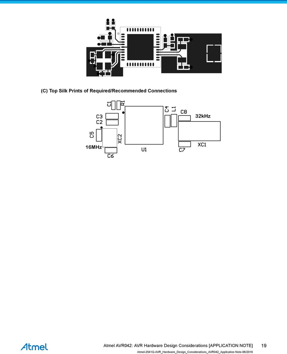
17 6. Example Layout of ATxmega32A4 and ATmega324PB device The basic schematic recommended for bringing up a design using ATxmega32A and ATmega324PB devices are shown in the following figures. The key points to be considered are: 1. The connections for crystal oscillator and de-coupling capacitors. 2. The number of layers of PCB. It is recommended to have a multilayer design with supply and ground plane on separate layers. 3. Decoupling of all digital supply pairs from VCC and isolating A VCC from V CC. 4. Short distance between the crystal/capacitors and the MCU. 5. Ground plane surrounding the crystal and the vias connected to the planes are close to the MCU pins in the layout. Figure 6-1. Example Layout for ATxmega32A4 device (A) Basic Schematic of Required/Recommended Connections 17

18 (B) Copper PCB Layout of Required/Recommended Connections (C) Top Silk Prints of Required/Recommended Connections Figure 6-2. Example Layout for ATmega324PB device (A) Basic Schematic of Required/Recommended Connections (B) Copper PCB Layout of Required/Recommended Connections 18
 Copper PCB Layout of")
19 (C) Top Silk Prints of Required/Recommended Connections 19
20 7. Revision History Doc Rev. Date Comments 2541Q 06/ General improvement of descriptions. 2. Added example layout for ATmega324PB device. 2541P 10/2015 Updated following sections: 1. About Crystals and Ceramic Resonators 2. Recommended Capacitor Values 2541O 09/2015 Corrected the figure Example Layout. 2521N 06/2015 Added Noise Implications. 2521M 09/2014 Fixed some typos in External RESET Switch. 2521L 07/ Updated Figure General improvements in regards of descriptions. 20

21 Atmel Corporation 1600 Technology Drive, San Jose, CA USA T: (+1)(408) F: (+1)(408) Atmel Corporation. / Rev.: Atmel, Atmel logo and combinations thereof, Enabling Unlimited Possibilities, AVR, tinyavr and others are registered trademarks or trademarks of Atmel Corporation in U.S. and other countries. Other terms and product names may be trademarks of others. DISCLAIMER: The information in this document is provided in connection with Atmel products. No license, express or implied, by estoppel or otherwise, to any intellectual property right is granted by this document or in connection with the sale of Atmel products. EXCEPT AS SET FORTH IN THE ATMEL TERMS AND CONDITIONS OF SALES LOCATED ON THE ATMEL WEBSITE, ATMEL ASSUMES NO LIABILITY WHATSOEVER AND DISCLAIMS ANY EXPRESS, IMPLIED OR STATUTORY WARRANTY RELATING TO ITS PRODUCTS INCLUDING, BUT NOT LIMITED TO, THE IMPLIED WARRANTY OF MERCHANTABILITY, FITNESS FOR A PARTICULAR PURPOSE, OR NON-INFRINGEMENT. IN NO EVENT SHALL ATMEL BE LIABLE FOR ANY DIRECT, INDIRECT, CONSEQUENTIAL, PUNITIVE, SPECIAL OR INCIDENTAL DAMAGES (INCLUDING, WITHOUT LIMITATION, DAMAGES FOR LOSS AND PROFITS, BUSINESS INTERRUPTION, OR LOSS OF INFORMATION) ARISING OUT OF THE USE OR INABILITY TO USE THIS DOCUMENT, EVEN IF ATMEL HAS BEEN ADVISED OF THE POSSIBILITY OF SUCH DAMAGES. Atmel makes no representations or warranties with respect to the accuracy or completeness of the contents of this document and reserves the right to make changes to specifications and products descriptions at any time without notice. Atmel does not make any commitment to update the information contained herein. Unless specifically provided otherwise, Atmel products are not suitable for, and shall not be used in, automotive applications. Atmel products are not intended, authorized, or warranted for use as components in applications intended to support or sustain life. SAFETY-CRITICAL, MILITARY, AND AUTOMOTIVE APPLICATIONS DISCLAIMER: Atmel products are not designed for and will not be used in connection with any applications where the failure of such products would reasonably be expected to result in significant personal injury or death ( Safety-Critical Applications ) without an Atmel officer's specific written consent. Safety-Critical Applications include, without limitation, life support devices and systems, equipment or systems for the operation of nuclear facilities and weapons systems. Atmel products are not designed nor intended for use in military or aerospace applications or environments unless specifically designated by Atmel as military-grade. Atmel products are not designed nor intended for use in automotive applications unless specifically designated by Atmel as automotive-grade.
APPLICATION NOTE. AVR042: AVR Hardware Design Considerations. AVR 8-bit Microcontrollers. Features. Description
 APPLICATION NOTE AVR042: AVR Hardware Design Considerations AVR 8-bit Microcontrollers Features Providing robust supply voltage, digital, and analog Connection of RESET line SPI interface for In-System
AVR151: Setup and Use of the SPI. Introduction. Features. Atmel AVR 8-bit Microcontroller APPLICATION NOTE
 Atmel AVR 8-bit Microcontroller AVR151: Setup and Use of the SPI APPLICATION NOTE Introduction This application note describes how to set up and use the on-chip Serial Peripheral Interface (SPI) of the
AVR127: Understanding ADC Parameters. Introduction. Features. Atmel 8-bit and 32-bit Microcontrollers APPLICATION NOTE
 Atmel 8-bit and 32-bit Microcontrollers AVR127: Understanding ADC Parameters APPLICATION NOTE Introduction This application note explains the basic concepts of analog-to-digital converter (ADC) and the
SMARTCARD XPRO. Preface. SMART ARM-based Microcontrollers USER GUIDE
 SMART ARM-based Microcontrollers SMARTCARD XPRO USER GUIDE Preface Atmel SMARTCARD Xplained Pro is an extension board to the Atmel Xplained Pro evaluation platform. Atmel SMARTCARD Xplained Pro is designed
AVR131: Using the AVR s High-speed PWM. Introduction. Features. AVR 8-bit Microcontrollers APPLICATION NOTE
 AVR 8-bit Microcontrollers AVR131: Using the AVR s High-speed PWM APPLICATION NOTE Introduction This application note is an introduction to the use of the high-speed Pulse Width Modulator (PWM) available
APPLICATION NOTE. Atmel AVR134: Real Time Clock (RTC) Using the Asynchronous Timer. Atmel AVR 8-bit Microcontroller. Introduction.
 Using the Asynchronous Timer. Atmel AVR 8-bit Microcontroller. Introduction.") APPLICATION NOTE Atmel AVR134: Real Time Clock (RTC) Using the Asynchronous Timer Introduction Atmel AVR 8-bit Microcontroller This application note describes how to implement a real time counter (RTC)
APPLICATION NOTE Atmel AVR134: Real Time Clock (RTC) Using the Asynchronous Timer Introduction Atmel AVR 8-bit Microcontroller This application note describes how to implement a real time counter (RTC)
Atmel AVR1017: XMEGA - USB Hardware Design Recommendations. 8-bit Atmel Microcontrollers. Application Note. Features.
 Atmel AVR1017: XMEGA - USB Hardware Design Recommendations Features USB 2.0 compliance - Signal integrity - Power consumption - Back driver voltage - Inrush current EMC/EMI considerations Layout considerations
AT11805: Capacitive Touch Long Slider Design with PTC. Introduction. Features. Touch Solutions APPLICATION NOTE
 Touch Solutions AT11805: Capacitive Touch Long Slider Design with PTC APPLICATION NOTE Introduction Slider is a one-dimensional sensor that detects the linear movement of a finger during touch. Sliders
AT15007: Differences between ATmega328/P and ATmega328PB. Introduction. Features. Atmel AVR 8-bit Microcontrollers APPLICATION NOTE
 Atmel AVR 8-bit Microcontrollers AT15007: Differences between ATmega328/P and ATmega328PB APPLICATION NOTE Introduction This application note assists the users of Atmel ATmega328 variants to understand
USER GUIDE EDBG. Description
 USER GUIDE EDBG Description The Atmel Embedded Debugger (EDBG) is an onboard debugger for integration into development kits with Atmel MCUs. In addition to programming and debugging support through Atmel
AT88CK490 Evaluation Kit
 AT88CK490 Evaluation Kit CryptoAuthentication USB Dongle HARDWARE USER GUIDE Atmel AT88CK490 CryptoAuthentication Evaluation Kit Introduction The Atmel AT88CK490 CryptoAuthentication Evaluation Kit is
USER GUIDE. ATWINC1500B Hardware Design Guidelines - IEEE 802.11 b/g/n IoT Module. Atmel SmartConnect. Introduction
 USER GUIDE ATWINC1500B Hardware Design Guidelines - IEEE 802.11 b/g/n IoT Module Atmel SmartConnect Introduction This document details the hardware design guidelines for a customer to design the Atmel
APPLICATION NOTE Atmel AT02509: In House Unit with Bluetooth Low Energy Module Hardware User Guide 8-bit Atmel Microcontroller Features Description
 APPLICATION NOTE Atmel AT259: In House Unit with Bluetooth Low Energy Module Hardware User Guide Features 8-bit Atmel Microcontroller Low power consumption Interface with BLE with UART Bi-direction wake
APPLICATION NOTE. AT07175: SAM-BA Bootloader for SAM D21. Atmel SAM D21. Introduction. Features
 APPLICATION NOTE AT07175: SAM-BA Bootloader for SAM D21 Atmel SAM D21 Introduction Atmel SAM Boot Assistant (Atmel SAM-BA ) allows In-System Programming (ISP) from USB or UART host without any external
QT1 Xplained Pro. Preface. Atmel QTouch USER GUIDE
 Atmel QTouch QT1 Xplained Pro USER GUIDE Preface Atmel QT1 Xplained Pro kit is a set of two extension boards that enables evaluation of self- and mutual capacitance mode touch using the Peripheral Touch
AVR126: ADC of megaavr in Single Ended Mode. Introduction. Features. AVR 8-bit Microcontrollers APPLICATION NOTE
 AVR 8-bit Microcontrollers AVR126: ADC of megaavr in Single Ended Mode APPLICATION NOTE Introduction Atmel megaavr devices have a successive approximation Analog-to- Digital Converter (ADC) capable of
AVR125: ADC of tinyavr in Single Ended Mode. 8-bit Microcontrollers. Application Note. Features. 1 Introduction
 AVR125: ADC of tinyavr in Single Ended Mode Features Up to 10bit resolution Up to 15kSPS Auto triggered and single conversion mode Optional left adjustment for ADC result readout Driver source code included
STK500... User Guide
 STK500... User Guide Table of Contents Section 1 Introduction... 1-1 1.1 Starter Kit Features...1-1 1.2 Device Support...1-2 Section 2 Getting Started... 2-1 2.1 Unpacking the System...2-1 2.2 System
AVR1922: Xplain Board Controller Firmware. 8-bit Microcontrollers. Application Note. Features. 1 Introduction
 AVR1922: Xplain Board Controller Firmware Features USB interface - Mass-storage to on-board DataFlash memory Atmel AVR XMEGA TM reset control 1 Introduction The Xplain board controller, an AT90USB1287,
The Programming Interface
 : In-System Programming Features Program any AVR MCU In-System Reprogram both data Flash and parameter EEPROM memories Eliminate sockets Simple -wire SPI programming interface Introduction In-System programming
ET-BASE AVR ATmega64/128
 ET-BASE AVR ATmega64/128 ET-BASE AVR ATmega64/128 which is a Board Microcontroller AVR family from ATMEL uses MCU No.ATmega64 and ATmega128 64PIN. Board ET-BASE AVR ATmega64/128 uses MCU s resources on
CryptoAuth Xplained Pro
 CryptoAuth Xplained Pro CryptoAuthentication Xplained Pro Extension Board HARDWARE USER GUIDE Atmel CryptoAuth Xplained Pro Extension Board Introduction The Atmel CryptoAuth Xplained Pro (CAXPro) Evaluation
AVR134: Real Time Clock (RTC) using the Asynchronous Timer. 8-bit Microcontrollers. Application Note. Features. 1 Introduction
 using the Asynchronous Timer. 8-bit Microcontrollers. Application Note. Features. 1 Introduction") AVR134: Real Time Clock (RTC) using the Asynchronous Timer Features Real Time Clock with Very Low Power Consumption (4 μa @ 3.3V) Very Low Cost Solution Adjustable Prescaler to Adjust Precision Counts
AVR134: Real Time Clock (RTC) using the Asynchronous Timer Features Real Time Clock with Very Low Power Consumption (4 μa @ 3.3V) Very Low Cost Solution Adjustable Prescaler to Adjust Precision Counts
AVR32138: How to optimize the ADC usage on AT32UC3A0/1, AT32UC3A3 and AT32UC3B0/1 series. 32-bit Microcontrollers. Application Note.
 AVR32138: How to optimize the ADC usage on AT32UC3A0/1, AT32UC3A3 and AT32UC3B0/1 series 1 Introduction This application note outlines the steps necessary to optimize analog to digital conversions on AT32UC3A0/1,
ICS379. Quad PLL with VCXO Quick Turn Clock. Description. Features. Block Diagram
 Quad PLL with VCXO Quick Turn Clock Description The ICS379 QTClock TM generates up to 9 high quality, high frequency clock outputs including a reference from a low frequency pullable crystal. It is designed
General Porting Considerations. Memory EEPROM XRAM
 AVR097: Migration between ATmega128 and ATmega2561 Features General Porting Considerations Memory Clock sources Interrupts Power Management BOD WDT Timers/Counters USART & SPI ADC Analog Comparator ATmega103
Atmel AVR ATxmega384C3 microcontroller OLED display with 128 32 pixels resolution Analog sensors. Ambient light sensor Temperature sensor
 APPLICATION NOTE AVR1925: XMEGA-C3 Xplained Hardware User s Guide Features Atmel AVR ATxmega384C3 microcontroller OLED display with 128 32 pixels resolution Analog sensors Ambient light sensor Temperature
August 2001 PMP Low Power SLVU051
 User s Guide August 2001 PMP Low Power SLVU051 IMPORTANT NOTICE Texas Instruments and its subsidiaries (TI) reserve the right to make changes to their products or to discontinue any product or service
AVR1301: Using the XMEGA DAC. 8-bit Microcontrollers. Application Note. Features. 1 Introduction
 AVR1301: Using the XMEGA DAC Features 12 bit resolution Up to 1 M conversions per second Continuous drive or sample-and-hold output Built-in offset and gain calibration High drive capabilities Driver source
AND8326/D. PCB Design Guidelines for Dual Power Supply Voltage Translators
 PCB Design Guidelines for Dual Power Supply Voltage Translators Jim Lepkowski ON Semiconductor Introduction The design of the PCB is an important factor in maximizing the performance of a dual power supply
8-bit RISC Microcontroller. Application Note. AVR910: In-System Programming
 AVR910: In-System Programming Features Complete In-System Programming Solution for AVR Microcontrollers Covers All AVR Microcontrollers with In-System Programming Support Reprogram Both Data Flash and
APPLICATION NOTE. Atmel AT01095: Joystick Game Controller Reference Design. 8-/16-bit Atmel Microcontrollers. Features.
 APPLICATION NOTE Features Atmel AT01095: Joystick Game Controller Reference Design 8-/16-bit Atmel Microcontrollers Joystick Game Controller Atmel ATxmega32A4U microcontroller In System Programming (ISP)
Atmel AT32UC3A3256 microcontroller 64MBit SDRAM Analog input (to ADC) Temperature sensor RC filter
 Temperature sensor RC filter") APPLICATION NOTE Features Atmel AVR32918: UC3-A3 Xplained Hardware User s Guide Atmel AT32UC3A3256 microcontroller 64MBit SDRAM Analog input (to ADC) Temperature sensor RC filter I/O One mechanical button
APPLICATION NOTE Features Atmel AVR32918: UC3-A3 Xplained Hardware User s Guide Atmel AT32UC3A3256 microcontroller 64MBit SDRAM Analog input (to ADC) Temperature sensor RC filter I/O One mechanical button
AVR106: C Functions for Reading and Writing to Flash Memory. Introduction. Features. AVR 8-bit Microcontrollers APPLICATION NOTE
 AVR 8-bit Microcontrollers AVR106: C Functions for Reading and Writing to Flash Memory APPLICATION NOTE Introduction The Atmel AVR devices have a feature called Self programming Program memory. This feature
APPLICATION NOTE. Authentication Counting. Atmel CryptoAuthentication. Features. Introduction
 APPLICATION NOTE Authentication Counting Atmel CryptoAuthentication Features How to achieve high endurance counters in excess of 800,000 counts. How to disable the Atmel CryptoAuthentication ATSHA204A
AVR033: Getting Started with the CodeVisionAVR C Compiler. 8-bit Microcontrollers. Application Note. Features. 1 Introduction
 AVR033: Getting Started with the CodeVisionAVR C Compiler Features Installing and Configuring CodeVisionAVR to Work with the Atmel STK 500 Starter Kit and AVR Studio Debugger Creating a New Project Using
Introducing AVR Dragon
 Introducing AVR Dragon ' Front Side Back Side With the AVR Dragon, Atmel has set a new standard for low cost development tools. AVR Dragon supports all programming modes for the Atmel AVR device family.
ICS514 LOCO PLL CLOCK GENERATOR. Description. Features. Block Diagram DATASHEET
 DATASHEET ICS514 Description The ICS514 LOCO TM is the most cost effective way to generate a high-quality, high-frequency clock output from a 14.31818 MHz crystal or clock input. The name LOCO stands for
Application Note, Rev.1.0, September 2008 TLE8366. Application Information. Automotive Power
 Application Note, Rev.1.0, September 2008 TLE8366 Automotive Power Table of Contents 1 Abstract...3 2 Introduction...3 3 Dimensioning the Output and Input Filter...4 3.1 Theory...4 3.2 Output Filter Capacitor(s)
AVR1900: Getting started with ATxmega128A1 on STK600. 8-bit Microcontrollers. Application Note. 1 Introduction
 AVR1900: Getting started with ATxmega128A1 on STK600 1 Introduction This document contains information about how to get started with the ATxmega128A1 on STK 600. The first three sections contain information
APPLICATION NOTE. Secure Personalization with Transport Key Authentication. ATSHA204A, ATECC108A, and ATECC508A. Introduction.
 APPLICATION NOTE Secure Personalization with Transport Key Authentication ATSHA204A, ATECC108A, and ATECC508A Introduction The Atmel CryptoAuthentication ATSHA204A, ATECC108A, and ATECC508A devices (crypto
AVR055: Using a 32kHz XTAL for run-time calibration of the internal RC. 8-bit Microcontrollers. Application Note. Features.
 AVR055: Using a 32kHz XTAL for run-time calibration of the internal RC Features Calibration using a 32 khz external crystal Adjustable RC frequency with maximum +/-2% accuracy Tune RC oscillator at any
Atmel Norway 2005. XMEGA Introduction
 Atmel Norway 005 XMEGA Introduction XMEGA XMEGA targets Leadership on Peripheral Performance Leadership in Low Power Consumption Extending AVR market reach XMEGA AVR family 44-100 pin packages 16K 51K
The Atmel-ICE Debugger
 Programmers and Debuggers Atmel-ICE USER GUIDE The Atmel-ICE Debugger Atmel-ICE is a powerful development tool for debugging and programming ARM Cortex -M based Atmel SAM and Atmel AVR microcontrollers
AVR317: Using the Master SPI Mode of the USART module. 8-bit Microcontrollers. Application Note. Features. Introduction
 AVR317: Using the Master SPI Mode of the USART module Features Enables Two SPI buses in one device Hardware buffered SPI communication Polled communication example Interrupt-controlled communication example
AVR1321: Using the Atmel AVR XMEGA 32-bit Real Time Counter and Battery Backup System. 8-bit Microcontrollers. Application Note.
 AVR1321: Using the Atmel AVR XMEGA 32-bit Real Time Counter and Battery Backup System Features 32-bit Real Time Counter (RTC) - 32-bit counter - Selectable clock source 1.024kHz 1Hz - Long overflow time
APPLICATION NOTE. Atmel AT04389: Connecting SAMD20E to the AT86RF233 Transceiver. Atmel SAMD20. Description. Features
 APPLICATION NOTE Atmel AT04389: Connecting SAMD20E to the AT86RF233 Transceiver Description Atmel SAMD20 This application note describes a method to connect an Atmel ATSAMD20E microcontroller to an Atmel
AVR311: Using the TWI Module as I2C Slave. Introduction. Features. AVR 8-bit Microcontrollers APPLICATION NOTE
 AVR 8-bit Microcontrollers AVR311: Using the TWI Module as I2C Slave APPLICATION NOTE Introduction The Two-wire Serial Interface (TWI) is compatible with Philips I 2 C protocol. The bus allows simple,
This application note is written for a reader that is familiar with Ethernet hardware design.
 AN18.6 SMSC Ethernet Physical Layer Layout Guidelines 1 Introduction 1.1 Audience 1.2 Overview SMSC Ethernet products are highly-integrated devices designed for 10 or 100 Mbps Ethernet systems. They are
AN1991. Audio decibel level detector with meter driver
 Rev. 2.1 20 March 2015 Application note Document information Info Keywords Abstract Content SA604A, LM358, RSSI, cellular radio The SA604A can provide a logarithmic response proportional to the input signal
Evaluation Board for the AAT1275 Boost Converter with USB Power Switch
 Introduction EVALUATION BOARD DATA SHEET The AAT1275 evaluation board provides a platform for test and evaluation of the AAT1275 switching boost converter with USB Power Switch. The evaluation board demonstrates
APPLICATION NOTE. Atmel AVR600: STK600 Expansion, Routing and Socket Boards. Atmel Microcontrollers. Introduction
 APPLICATION NOTE Atmel AVR600: STK600 Expansion, Routing and Socket Boards Introduction Atmel Microcontrollers This application note describes the process of developing new routing, socket and expansion
AVR315: Using the TWI Module as I2C Master. Introduction. Features. AVR 8-bit Microcontrollers APPLICATION NOTE
 AVR 8-bit Microcontrollers AVR315: Using the TWI Module as I2C Master APPLICATION NOTE Introduction The Two-wire Serial Interface (TWI) is compatible with Philips I 2 C protocol. The bus allows simple,
SAMA5D2. Scope. Reference Documents. Atmel SMART ARM-based MPU ERRATA
 SAMA5D2 Atmel SMART ARM-based MPU ERRATA Scope This document contains the known errata found on the following Atmel SMART ARM -based SAMA5D2 devices, and planned to be fixed in the next silicon version:
GTS-4E Hardware User Manual. Version: V1.1.0 Date: 2013-12-04
 GTS-4E Hardware User Manual Version: V1.1.0 Date: 2013-12-04 Confidential Material This document contains information highly confidential to Fibocom Wireless Inc. (Fibocom). Fibocom offers this information
AN10724. TDA8026ET - 5 slots smart card interface. Document information
 Rev. 1.0 27 September 2011 Application note Document information Info Content Keywords TDA8026, 5 slots, Smart Card Interface, Banking, EMV, Point-Of-Sale, ISO 7816-3 Abstract This application note describes
APPLICATION NOTE. AT12405: Low Power Sensor Design with PTC. Atmel MCU Integrated Touch. Introduction
 APPLICATION NOTE AT12405: Low Power Sensor Design with PTC Atmel MCU Integrated Touch Introduction A ma saved (reduced) is a mah gained the philosophical engineer The challenges for improving battery life
8-bit Microcontroller. Application Note. AVR134: Real-Time Clock (RTC) using the Asynchronous Timer. Features. Theory of Operation.
 using the Asynchronous Timer. Features. Theory of Operation.") AVR134: Real-Time Clock (RTC) using the Asynchronous Timer Features Real-Time Clock with Very Low Power Consumption (4µA @ 3.3V) Very Low Cost Solution Adjustable Prescaler to Adjust Precision Counts Time,
AVR134: Real-Time Clock (RTC) using the Asynchronous Timer Features Real-Time Clock with Very Low Power Consumption (4µA @ 3.3V) Very Low Cost Solution Adjustable Prescaler to Adjust Precision Counts Time,
Supply voltage Supervisor TL77xx Series. Author: Eilhard Haseloff
 Supply voltage Supervisor TL77xx Series Author: Eilhard Haseloff Literature Number: SLVAE04 March 1997 i IMPORTANT NOTICE Texas Instruments (TI) reserves the right to make changes to its products or to
DATASHEET. ADAM Arduino Display Adaptor Module. Arduino Compatible Shield P/N: 4Display-Shield-FT843 For the 4D Systems 4DLCD-FT843 Display
 DATASHEET ADAM Arduino Display Adaptor Module Arduino Compatible Shield P/N: 4Display-Shield-FT843 For the 4D Systems 4DLCD-FT843 Display Document Date: 8 th January 2014 Document Revision: 1.0 Uncontrolled
AN10950. LPC24XX external memory bus example. Document information
 Rev. 1.1 9 November 2012 Application note Document information Info Content Keywords LPC24XX, EMC, memory, SDRAM, SRAM, flash Abstract This application note will detail an example design illustrating how
AN111: Using 8-Bit MCUs in 5 Volt Systems
 This document describes how to incorporate Silicon Lab s 8-bit EFM8 and C8051 families of devices into existing 5 V systems. When using a 3 V device in a 5 V system, the user must consider: A 3 V power
AVR319: Using the USI module for SPI communication. 8-bit Microcontrollers. Application Note. Features. Introduction
 AVR319: Using the USI module for SPI communication Features C-code driver for SPI master and slave Uses the USI module Supports SPI Mode 0 and 1 Introduction The Serial Peripheral Interface (SPI) allows
MFRD52x. Mifare Contactless Smart Card Reader Reference Design. Document information
 Rev. 2.1 17. April 2007 Preliminary Data Sheet Document information Info Keywords Content MFRC522, MFRC523, MFRC52x, MFRD522, MFRD523, Mifare Contactless Smart Card Reader Reference Design, Mifare Reader
How To Design An Ism Band Antenna For 915Mhz/2.4Ghz Ism Bands On A Pbbb (Bcm) Board
 Board") APPLICATION NOTE Features AT09567: ISM Band PCB Antenna Reference Design Atmel Wireless Compact PCB antennas for 915MHz and 2.4GHz ISM bands Easy to integrate Altium design files and gerber files Return
APPLICATION NOTE Features AT09567: ISM Band PCB Antenna Reference Design Atmel Wireless Compact PCB antennas for 915MHz and 2.4GHz ISM bands Easy to integrate Altium design files and gerber files Return
M68EVB908QL4 Development Board for Motorola MC68HC908QL4
 M68EVB908QL4 Development Board for Motorola MC68HC908QL4! Axiom Manufacturing 2813 Industrial Lane Garland, TX 75041 Email: [email protected] Web: http://www.axman.com! CONTENTS CAUTIONARY NOTES...3 TERMINOLOGY...3
NTE2053 Integrated Circuit 8 Bit MPU Compatible A/D Converter
 NTE2053 Integrated Circuit 8 Bit MPU Compatible A/D Converter Description: The NTE2053 is a CMOS 8 bit successive approximation Analog to Digital converter in a 20 Lead DIP type package which uses a differential
SM1231 USER GUIDE SM1231 RF MODULE USER GUIDE
 SM1231 RF MODULE Revision 1.0 11/2009 Page 1 of 8 www.semtech.com Table of Contents Table of Contents...2 Index of Figures...2 Index of Tables...2 1 Introduction...3 2 Reference Design...3 3 PCB Layout...6
Chapter 6 PLL and Clock Generator
 Chapter 6 PLL and Clock Generator The DSP56300 core features a Phase Locked Loop (PLL) clock generator in its central processing module. The PLL allows the processor to operate at a high internal clock
AVR1003: Using the XMEGA Clock System. 8-bit Microcontrollers. Application Note. Features. 1 Introduction
 AVR1003: Using the XMEGA Clock System Features Internal 32 khz, 2 MHz, and 32 MHz oscillators External crystal oscillator or clock input Internal PLL with multiplication factor 1x to 31x Safe clock source
Cold-Junction-Compensated K-Thermocoupleto-Digital Converter (0 C to +1024 C)
") 19-2235; Rev 1; 3/02 Cold-Junction-Compensated K-Thermocoupleto-Digital General Description The performs cold-junction compensation and digitizes the signal from a type-k thermocouple. The data is output
19-2235; Rev 1; 3/02 Cold-Junction-Compensated K-Thermocoupleto-Digital General Description The performs cold-junction compensation and digitizes the signal from a type-k thermocouple. The data is output
Output Filter Design for EMI Rejection of the AAT5101 Class D Audio Amplifier
 The AAT50 is a high efficiency, 2.5W mono class D audio power amplifier. It can be used in portable devices, such as MP4s, cell phones, laptops, GPS and PDAs. The device can work as a filterless class
The Atmel-ICE Debugger
 USER GUIDE Atmel-ICE The Atmel-ICE Debugger Atmel-ICE is a powerful development tool for debugging and programming ARM Cortex -M based Atmel SAM and Atmel AVR microcontrollers with OnChip Debug capability.
APPLICATION NOTE. Atmel AVR443: Sensor-based Control of Three Phase Brushless DC Motor. Atmel AVR 8-bit Microcontrollers. Features.
 APPLICATION NOTE Features Atmel AVR443: Sensor-based Control of Three Phase Brushless DC Motor Less than 5µs response time on Hall sensor output change Theoretical maximum of 1600k RPM Over-current sensing
AVR1309: Using the XMEGA SPI. 8-bit Microcontrollers. Application Note. Features. 1 Introduction SCK MOSI MISO SS
 AVR1309: Using the XMEGA SPI Features Introduction to SPI and the XMEGA SPI module Setup and use of the XMEGA SPI module Implementation of module drivers Polled master Interrupt controlled master Polled
USER GUIDE. ZigBit USB Stick User Guide. Introduction
 USER GUIDE ZigBit USB Stick User Guide Introduction This user guide describes how to get started with the Atmel ZigBit USB sticks. The ZigBit USB sticks is targeted for evaluating the USB features of the
8-Bit Flash Microcontroller for Smart Cards. AT89SCXXXXA Summary. Features. Description. Complete datasheet available under NDA
 Features Compatible with MCS-51 products On-chip Flash Program Memory Endurance: 1,000 Write/Erase Cycles On-chip EEPROM Data Memory Endurance: 100,000 Write/Erase Cycles 512 x 8-bit RAM ISO 7816 I/O Port
Application Note, V 2.2, Nov. 2008 AP32091 TC1766. Design Guideline for TC1766 Microcontroller Board Layout. Microcontrollers. Never stop thinking.
 Application Note, V 2.2, Nov. 2008 AP32091 TC1766 Design Guideline for TC1766 Microcontroller Board Layout Microcontrollers Never stop thinking. Edition Published by Infineon Technologies AG 81726 München,
AN3265 Application note
 Application note Handling hardware and software failures with the STM8S-DISCOVERY Application overview This application is based on the STM8S-DISCOVERY. It demonstrates how to use the STM8S window watchdog
APPLICATION NOTE. AT16268: JD Smart Cloud Based Smart Plug Getting. Started Guide ATSAMW25. Introduction. Features
 APPLICATION NOTE AT16268: JD Smart Cloud Based Smart Plug Getting Started Guide ATSAMW25 Introduction This application note aims to help readers to get started with the Atmel smart plug reference design
TURBO PROGRAMMER USB, MMC, SIM DEVELOPMENT KIT
 TURBO PROGRAMMER USB, MMC, SIM DEVELOPMENT KIT HARDWARE GUIDE This document is part of Turbo Programmer documentation. For Developer Documentation, Applications and Examples, see http:/// PRELIMINARY (C)
AVR353: Voltage Reference Calibration and Voltage ADC Usage. 8-bit Microcontrollers. Application Note. Features. 1 Introduction
 AVR353: Voltage Reference Calibration and Voltage ADC Usage Features Voltage reference calibration. - 1.100V +/-1mV (typical) and < 90ppm/ C drift from 10 C to +70 C. Interrupt controlled voltage ADC sampling.
AVR305: Half Duplex Compact Software UART. 8-bit Microcontrollers. Application Note. Features. 1 Introduction
 AVR305: Half Duplex Compact Software UART Features 32 Words of Code, Only Handles Baud Rates of up to 38.4 kbps with a 1 MHz XTAL Runs on Any AVR Device Only Two Port Pins Required Does Not Use Any Timer
WICE-SPI Hardware Operation Manual
 Contents 1.Hardware Instruction...1 2. Pin Definition Of WICE-SPI Connector...2 3. Peripheral Circuit Arrangements...3 4. On-Board Programming...4 5. Off-Line Programming...8 1.Hardware Instruction 1.WICE-SPI
8-bit Microcontroller. Application Note. AVR400: Low Cost A/D Converter
 AVR400: Low Cost A/D Converter Features Interrupt Driven : 23 Words Low Use of External Components Resolution: 6 Bits Measurement Range: 0-2 V Runs on Any AVR Device with 8-bit Timer/Counter and Analog
Output Ripple and Noise Measurement Methods for Ericsson Power Modules
 Output Ripple and Noise Measurement Methods for Ericsson Power Modules Design Note 022 Ericsson Power Modules Ripple and Noise Abstract There is no industry-wide standard for measuring output ripple and
AN11007. Single stage 5-6 GHz WLAN LNA with BFU730F. document information
 Single stage 5-6 GHz WLAN LNA with BFU730F Rev. 2 20 November 2012 Application note document information Info Content Keywords BFU730F, LNA, 802.11a & 802.11n MIMO WLAN Abstract The document provides circuit,
8-bit. Application Note. Microcontrollers. AVR282: USB Firmware Upgrade for AT90USB
 AVR282: USB Firmware Upgrade for AT90USB Features Supported by Atmel FLIP program on all Microsoft O/S from Windows 98SE and later FLIP 3.2.1 or greater supports Linux Default on chip USB bootloader In-System
JTAG-HS2 Programming Cable for Xilinx FPGAs. Overview. Revised January 22, 2015 This manual applies to the HTAG-HS2 rev. A
 1300 Henley Court Pullman, WA 99163 509.334.6306 www.digilentinc.com Programming Cable for Xilinx FPGAs Revised January 22, 2015 This manual applies to the HTAG-HS2 rev. A Overview The Joint Test Action
Input and Output Capacitor Selection
 Application Report SLTA055 FEBRUARY 2006 Input and Output Capacitor Selection Jason Arrigo... PMP Plug-In Power ABSTRACT When designing with switching regulators, application requirements determine how
Application Note 58 Crystal Considerations for Dallas Real-Time Clocks
 www.maxim-ic.com Application Note 58 Crystal Considerations for Dallas Real-Time Clocks OVERVIEW This application note describes crystal selection and layout techniques for connecting a 32,768Hz crystal
SMS7630-061: Surface Mount, 0201 Zero Bias Silicon Schottky Detector Diode
 DATA SHEET SMS7630-061: Surface Mount, 0201 Zero Bias Silicon Schottky Detector Diode Applications Sensitive RF and microwave detector circuits Sampling and mixer circuits High volume wireless systems
PL-277x Series SuperSpeed USB 3.0 SATA Bridge Controllers PCB Layout Guide
 Application Note PL-277x Series SuperSpeed USB 3.0 SATA Bridge Controllers PCB Layout Guide Introduction This document explains how to design a PCB with Prolific PL-277x SuperSpeed USB 3.0 SATA Bridge
Software Real Time Clock Implementation on MC9S08LG32
 Freescale Semiconductor Document Number: AN4478 Rev. 0, 03/2012 Software Real Time Clock Implementation on MC9S08LG32 by: Nitin Gupta Automotive and Industrial Solutions Group 1 Introduction The MC9S08LG32
APPLICATION NOTE. RF System Architecture Considerations ATAN0014. Description
 APPLICATION NOTE RF System Architecture Considerations ATAN0014 Description Highly integrated and advanced radio designs available today, such as the Atmel ATA5830 transceiver and Atmel ATA5780 receiver,
Application Note 58 Crystal Considerations with Dallas Real Time Clocks
 www.dalsemi.com Application Note 58 Crystal Considerations with Dallas Real Time Clocks Dallas Semiconductor offers a variety of real time clocks (RTCs). The majority of these are available either as integrated
SKY13380-350LF: 20 MHz-3.0 GHz High Power SP4T Switch With Decoder
 DATA SHEET SKY13380-350LF: 20 MHz-3.0 GHz High Power SP4T Switch With Decoder Applications GSM/WCDMA/EDGE datacards and handsets Mobile high power switching systems Features Broadband frequency range:
AN2680 Application note
 Application note Fan speed controller based on STDS75 or STLM75 digital temperature sensor and ST72651AR6 MCU Introduction This application note describes the method of defining the system for regulating
AVR1600: Using the XMEGA Quadrature Decoder. 8-bit Microcontrollers. Application Note. Features. 1 Introduction. Sensors
 AVR1600: Using the XMEGA Quadrature Decoder Features Quadrature Decoders 16-bit angular resolution Rotation speed and acceleration 1 Introduction Quadrature encoders are used to determine the position
UM1613 User manual. 16-pin smartcard interface ST8034P demonstration board. Introduction
 User manual 16-pin smartcard interface ST8034P demonstration board Introduction The purpose of this document is to describe, and provide information on, how to efficiently use the ST8034P smartcard interface