The G-QRP Club. The Limerick Sudden 40m Receiver Kit
|
|
|
- Lionel Lang
- 9 years ago
- Views:
Transcription
1 The G-QRP Club The Limerick Sudden 40m Receiver Kit Circuit design George Dobbs G3RJV PCB design Rex Harper W1REX Kit parts spec and purchase Graham Firth G3MFJ Manual G3RJV and G3MFJ soku=j~ó=omnp= 1

2 The G-QRP Club Founded in 1974, the G-QRP Club is the largest QRP Club in the world. The club exists to promote interest and growth in low power amateur radio communication (5 watts or less). Membership is open to any licensed radio amateur or short wave listener anywhere in the world. The club publishes a quarterly journal called SPRAT, which is sent free to members. SPRAT contains many circuits, technical hints and ideas for QRP construction projects, together with club news, contest and award information and other items of interest to QRP operators. SPRAT is an exclusive QRP journal and contains much practical information in each issue. The club operates a club sales department where components are available at special prices to club members. We also publish QRP books which are available to members. If you are not a member, and would like to find out more, please look at For a sample SPRAT and a membership form, please send your name and address to our membership secretary: Tony Fishpool, PO Box 298, Dartford, Kent. DA1 9DQ. [email protected] Please mention where you saw this information soku=j~ó=omnp= 2

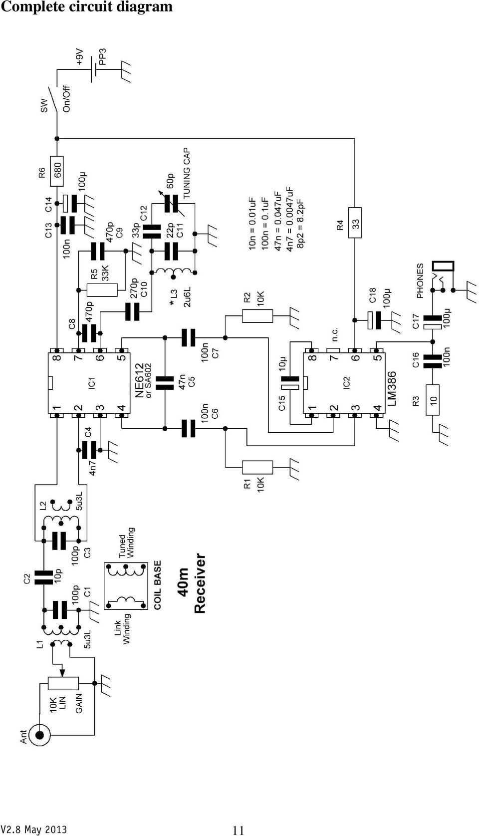
3 Background The Limerick Sudden is built around two integrated circuit chips; the SA602 * and the LM386. Both lend themselves to simple receiver construction; although neither has particularly high performance in that application. Having said that, the Sudden is a remarkable receiver for what it contains. It covers the full 40m ham band and receives CW and SSB very well. The original Sudden began life over 20 years ago in SPRAT and was then published in Practical Wireless followed by the 73 magazine in the U.S.A. Since then several versions and modifications to the Sudden receiver have been written up; although very few of them were written by me. The original naming of the Sudden had nothing to do with rapidity or hastiness but was taken from the name of the place where I lived and worked. The SPRAT version was available as a kit from Kanga Products. The kit proved very popular with beginners and several groups used it as a training project with young people. There was even a surface mount version; produced for a while by Blue Rose Electronics. In more recent times a version of the receiver was packaged in a tuna tin on a circular printed circuit board and called The Sudden Storm by W1REX at qrpme.com. The Circuit The Sudden has only two active components: IC1, an SA602* chip which contains a mixer and an oscillator and IC2, an LM386 audio amplifier chip. The signal at the antenna input goes directly to an attenuator; a 10K linear potentiometer that serves as the receiver GAIN control. The required signals are selected by a two stage band-pass filter. There are two tuned circuits L1/C1 and L2/C3 loosely coupled by C2. Note that the tuned windings of L1 and L2 have a centre tap connection that is not used. Only the two outer connections are used. The link winding of L1 receives the signals from the gain control but the link winding of L2 is unused, the output being taken from across the tuned winding. The output from the band-pass filter goes to the input of the mixer at pins 1 and 2 of IC1. IC1 contains an internal oscillator circuit that is accessed via pins 6 and 7. This is a version of the Colpitts oscillator; the frequency of which is determined by L3 and its associated capacitors and adjusted by the 60pF Tuning Capacitor. The oscillator is tuned across the required amateur band. The mixer section of IC1 mixes the signals from the band-pass filter and the signal from the oscillator and the resulting signals appear at pins 4 and 5. An audio (sound) output will appear at the upper and lower sidebands of the oscillator frequency. These are the signals we require. The required audio signals are fed to IC2 via C6 and C7; this uses the balanced input to the LM386. C15 between pins 1 and 8 of IC2 (the gain control pins) gives the maximum voltage gain of about 45dB. The output appears at pin 5 and is fed to the output jack via C18. C16 and R3 form a filter (called a zobel network) to aid amplifier stability. The output of the LM386 is about 350 milli-watts. This will drive a small loudspeaker although it works better with walkman-type headphones. * Whilst the SA602 designation is used throughout this manual, your kit may contain an NE602, an NE612, or an SA612. All the electronics are identical the differences (if any), are either cosmetic or the package construction material. soku=j~ó=omnp= 3

4 Building your kit You will have noticed that this is a rather unusual kit. It has a printed circuit board without any holes. We call it Limerick Construction because it was designed by Rex Harper, W1REX, of Limerick, Maine. It is a surface mounted board in that the components are mounted on the surface of the board, although the components used are through-hole parts. This allows for ease of construction and easy correction of any errors. The main board also has the front and back panels for the receiver. They are scored and can be snapped off the main board. We suggest you smooth the snapped off edges with emery paper or an emery board. The component parts are soldered to the top surface of the board using the leads that would go through the board on a conventional printed circuit board. The interconnections between the mounting pads are ready made but hidden by the black screen printed overlay. The designation of all the parts is printed next to the appropriate pads. There is merit in following this order in construction. Note that the instructions refer to having the board so that the legends for the components read the correct way round (PP3 at the top right). The best results will come from the use of medium size soldering iron and Tin/Lead solder. It does help to set out all the components in the order they will be used. The best way is to use a small piece of polystyrene to hold the individual parts. Mount the IC holders first. Bend the pins of the IC holder to be flush with the base of the holder; splayed out either side of the body of the holder. Tin (add a solder layer) to each pin. Notice that there is an indentation between pins 1 and 8. (Pin 1 is on the left, pin 8 on the right). This indentation also occurs on the IC holder. This shows the correct way to connect the IC. Tin the pads for IC1 and IC2. Place the IC holder over the pads so that the pins rest on the appropriate pads. Using the soldering iron, plus a little solder, secure the IC holder at pin 8 (top right). Check that the IC holder is properly aligned and secure pin 4 (diagonally opposite to pin 8). Then secure each of the 8 pins by applying the iron and a little more solder. At this point it may be helpful to check the continuity of the connections by using a multimeter set on the lowest ohms range with the probes between the top connections on the IC holder and the appropriate pad. This is probably the most difficult soldering job. It is all down hill from this point! soku=j~ó=omnp= 4

5 Mount the coils The oscillator coil, L3, is a 2u6L component, and the bandpass filter coils are 5u3L components. The coils have a solder lug on each side as part of the screened can. Bend these out 90 degrees and cut them off. Tin the leads of all 5 pins on the coil a nice blob of solder on each one. Tin the 5 pads for each coil (L1, L2 and L3). Note that the side of the coil with 3 connections has the pads mounted closely, so avoid using excessive solder and bridging the gaps between these pins. Seat the coil pins (do not bend them) over the pads and secure one of the pins with a little solder and the hot tip of the soldering iron. Check that the other pins align with the pads and solder each of the pins to the pads. Closely inspect the 3 pin side of each coil for accidental solder bridges. Mount the passive components The passive components (resistors and capacitors) can now be added. Begin with the resistors (R1 to R6). The colour code for the resistors is given in the parts list. To enable a secure solder connection of the parts, the leads are bent into an L shape for adding to the pads on the board. The bent out portion of the lead forms a foot for soldering to the pad. Tin each foot and each pad and firmly solder the component into place The capacitors (C1 to C18) can now be mounted; trimming and bending the leads for soldering to the pads. The value designation for each capacitor is shown in the parts list. Check carefully that the correct capacitor is chosen for each place. There are four electrolytic capacitors (C14, C15, C17, and C18). These capacitors are polarised and must be connected the correct way round on the pads. A stripe down one side of the capacitor case, with dashed lines, indicates the negative side of the capacitor. Looking at the board with the parts markings the correct way up (PP3 on the right hand side) C14, C15, C17 and C18 all have the negative (striped side) connected to the right hand pad. The components are all now mounted on the board so this is a good time to inspect the connections to check that all the solder joints are clean and firm. soku=j~ó=omnp= 5
 over the pads and secure one of the pins with a little solder and the hot tip of the soldering iron.")
6 Add the side cheeks cêçåí= This is also a good time to solder the side cheeks into place either side of the main board. These are designed as fixing plates for the enclosure. Be careful to get these the correct way round - the holes are not equally spaced from the ends. They should be placed so that the holes are nearer the front panel this lets the case overhang at the front to give a hooded effect. Adding the side cheeks at this point does mean that the fixing of the front and back panels of the receiver is much easier. Attaching the side cheeks does require a really hot soldering iron bit and plenty of solder. The side cheeks should be soldered on top of the main board and we suggest that you begin with a large blob of solder at each end to fix the position. Attempt to get the side cheek as near vertical as possible. You may freely run more solder along the narrow pads on the length of the board when you are happy with the position. The front panel The front panel holds the tuning capacitor, the gain control potentiometer and the phones socket. Like the side cheeks it is soldered to the main board. The panel should be soldered underneath as well as on top for extra strength. The gain control The gain control potentiometer shaft needs to be prepared, cutting it down to about 1 cm long so that the knob can seat close to the front panel. This can be done with a small hacksaw. The gain potentiometer connections are shown; numbered 1, 2 and 3. The tuning capacitor The tuning capacitor is a two section polyvaricon type but only the section with the smallest capacitance is used. There are markings (rather small) to indicate the capacitance of each section. A = 140pF, O = 60pF and G = Ground. We only require the O and G connections. The A solder tag can be removed to avoid confusion. The connections to the pads on the board are shown here. The capacitor should be mounted tags downwards this makes the connections shorter. If you get the connections reversed, the receiver will still work, but there will be a change of frequency as your hand approaches the tuning control. The tuning capacitor is mounted to the front panel using two small screws provided. soku=j~ó=omnp= 6

7 The phones socket To enable a pair of walkman-type headphones to be used with the receiver the phones socket must be connected as shown. The two connectors at the back of the socket are joined and connected to the PHONES + pad and the connector at the front is connected to the PHONES pad. We suggest that you connect the wires to the socket first, cut them to length (3 to 4cm) and then solder the other ends to the board before fixing the socket to the front panel as space is a little tight here. The back panel The back panel contains the antenna input socket and the power on-off switch. Like the front panel it is soldered to the main board. Again, remember to solder it underneath as well as on top. Now might be a good time to stick the self adhesive feet under the base. The antenna input socket The antenna input socket is a single hole fixing phono socket. It has a ground connection tag that needs to be inside the back panel. Bend this tag inwards for a wire that connects to the gnd pad. The antenna input connection is soldered to the ANT pad. Use differing colours to identify the two leads and twist them together. The power switch The power switch enables the PP3 battery to be switched on and off. When the switch level is in the down position, the two contacts marked here will be joined. Use two wires to connect these contacts to the SW pads (either way round). Cut the leads on the PP3 battery snap on connector to about 4 5 cm and connect them to the 9V pads; red to +, black to -. Adding the ICs Before pushing the ICs into the holders, the pins need to be pushed slightly inwards. The easiest way to do this is to lay the IC pins (one side at a time) against a flat surface and gently push them very slightly inwards until both rows of pins are parallel and they line up with the holes in the sockets. Push them into place very gently. They must be mounted the correct way round in the holder. The end with the indentation (and the dot at pin 1) goes to the end with the indentation on the board placement markings. This is towards the back of the board in both cases. The wiring of the receiver is now complete so you may want to check the board for correct placements and good solder joints before applying power. soku=j~ó=omnp= 7

8 Setting Up the Receiver Oscillator Ideally a frequency counter, a signal generator, or even another receiver that covers the same frequency may be used to set up your Sudden. For those without these items of test equipment, it is quite possible to set it up by ear. Using a frequency counter to set up the receiver oscillator. L3, the oscillator coil, has an unused link winding. This may be used to feed a frequency counter. Connect one (either) side of the link winding to ground and use the other end to connect to the counter. Some counters may detune the frequency a little so putting a low value capacitor (47 to 100pF) between the counter and the link winding is advised. Set the Tuning Capacitor control fully anti-clockwise and adjust the core to read a frequency just below 7.0 MHz. Be warned! Rough use of the adjustable core can break it. Ideally use a proper trimming tool in the slot on the core. If a trimming tool is not available you could file a screwdriver blade shape on a thin knitting needle or even a cocktail stick. If you must use a small screwdriver. do it with great care as the cores are very brittle. Take care not to screw the core right through the coil as you will have to remove the coil to get it back into the coil! Using a signal generator to set up the receiver oscillator. Set the signal generator on 7.0 MHz and feed the signal into the antenna input. Begin with a low output from the signal generator and only increase the output if it cannot be detected by the receiver. Set the Tuning Capacitor control almost fully anti-clockwise and gently rotate the core of L3 until the generator signal is heard. Setting the oscillator frequency by ear Connect an antenna to the receiver input (a decent antenna is helpful) and set the Tuning Capacitor nearly anti-clockwise. Adjust the core of L3 until CW (Morse) signals on the 7 MHz band can be heard. A good starting point is with the core 1 complete turn downwards from when it is flush with the top of the former. The strength of the signals will depend upon the time of day. It will require some experimentation to find the low end of the band. Try to find the lowest frequency CW signal. Setting the oscillator frequency with another receiver If you place the antenna lead of the other receiver near to your Sudden, then you can look for the VFO as a steady carrier signal. If the tuning dial is fully counter-clockwise, the signal should be just under 7MHz. You should adjust the core of L3 until you hear the signal. Again, the tool you are using to adjust the core may affect the frequency. The receiver will easily cover the whole of the 7MHz amateur band, plus a little extra on either side. soku=j~ó=omnp= 8
 side of the link winding to ground and use the other end to connect to the counter.")

9 Setting up the input filter The two input tuned circuits L1/C1 and L2/C3 are set to maximum output using the cores in L1 and L2. Use a trimming tool or work very carefully with a small slotted screwdriver. L1 and L2 can be peaked for maximum signal strength using a signal generator or amateur band signals. Even if using a signal generator it is an advantage to do a final adjustment listening to band signals; these are what we will be using the receiver for. Use the best available antenna for these adjustments. Adjust L1 first for a peak in the signals and then adjust L2. Repeat this several times until the best results are obtained. Again, take care not to screw either core right through its coil! The position of the core will vary with individual receivers because of the tolerance of C1 and C3 and the nominal inductance of individual coils. Usually the input filter will peak with the core set at about two complete turns downwards from the position where the core is flush with the top of the coil former. Remember that the filter is based on a nominal input impedance of 50 ohms so a 50 ohm impedance antenna or an antenna tuning unit will obtain the best results. Finally the case The case parts should now be soldered together the important point here is that the sides must be at right-angles to the top. Again, use the single blob technique until you are satisfied with the angles it is better if you do not solder right up to the front of the lid as the case overlaps the front to give a hooded effect, and if you solder right up to the front, the case may not fit as well. If you wish, you can fasten the case to the base with the supplied self-tapping screws. Layout of Printed Circuit Board soku=j~ó=omnp= 9

10 Component List Resistors Value Markings R1 10k brown black orange gold R2 10k brown black orange gold R3 10 brown black black gold R4 33 orange orange black gold R5 33k orange orange orange gold R6 680 blue grey brown gold Capacitors (all non-electrolytic capacitors are Light brown unless another colour is shown) C1 100pF 101 C2 10pF 10 C3 100pF 101 C4 4n7 472 C5 47n 473 C6 100nF 1042 or 104 C7 100nF 1042 or 104 C8 470pF 471 (yellow) C9 470pF 471 (yellow) C10 270pF 271 (yellow) C11 22pF 22P (light grey) C12 33pF 33P (blue) C13 100nF 1042 or 104 C14 100uF 100uF 16V C15 10uF 10uF 25V C16 100nF 1042 or 104 C17 100uF 100uF 16V C18 100uF 100uF 16V Inductors L1 L2 L3 5u3L 5u3L 2u6L Semiconductors Mixer/oscillator IC 1 SA602AN Audio amplifier IC 2 LM386N-1 * an SA602 or SA612 may be supplied Other parts VR 1 10k RF Gain VC 1 60pF polyvaricon Tuning Screws For tuning capacitor SW miniature toggle switch on/off switch Skt 1 3.5mm stereo jack socket Phones Skt 2 Phono/RCA socket Antenna Batt clip PP3 clip 8 pin IC socket x 2 Knobs 15mm and 35mm Wire 3 colours of wire Battery PP3 2 off PCBs Board/front/rear and case 4 feet Self adhesive feet For the base Screws 4 off self tapping To fasten the case soku=j~ó=omnp= 10

11 Complete circuit diagram soku=j~ó=omnp= 11
12 Top view of completed receiver G-QRP Club 2010/11/12/13 soku=j~ó=omnp= 12

13 soku=j~ó=omnp= 13

The RSGB Centenary Receiver Project Construction Manual
 The RSGB Centenary Receiver Project Construction Manual Page 1 of 12 Introduction This project is intended for those new to radio construction. It is a fairly simple receiver for the 14MHz (20m) amateur
Assembly Instructions: Shortwave Radio Kit
 Assembly Instructions: Shortwave Radio Kit MTM Scientific, Inc P.O. Box 522 Clinton, MI 49236 U.S.A Introduction Fig 1: The assembled Shortwave Radio Kit The SHORTWAVE RADIO KIT (#SWRAD) from MTM Scientific
Modifying the Yaesu FT-847 External 22.625 MHz Reference Input
 Modifying the Yaesu FT-847 External 22.625 MHz Reference Input David Smith VK3HZ Introduction This document describes the modification of an FT-847 to allow an external 22.625 MHz Reference oscillator
Cumbria Designs T-1. SSB/CW Filter kit (4.9152MHz) User Manual
 User Manual") Cumbria Designs T-1 SSB/CW Filter kit (4.9152MHz) User Manual CONTENTS 1 INTRODUCTION 2 2 CIRCUIT DESCRIPTION 2 3 ASSEMBLY 2 4 TESTING 4 The Steading Stainton PENRITH Cumbria CA11 0ES UK 1 Introduction
Cumbria Designs T-1 SSB/CW Filter kit (4.9152MHz) User Manual CONTENTS 1 INTRODUCTION 2 2 CIRCUIT DESCRIPTION 2 3 ASSEMBLY 2 4 TESTING 4 The Steading Stainton PENRITH Cumbria CA11 0ES UK 1 Introduction
TEACHING RESOURCES SCHEMES OF WORK DEVELOPING A SPECIFICATION COMPONENT FACTSHEETS HOW TO SOLDER GUIDE GET IN TUNE WITH THIS FM RADIO KIT. Version 2.
 TEACHING RESOURCES SCHEMES OF WORK DEVELOPING A SPECIFICATION COMPONENT FACTSHEETS HOW TO SOLDER GUIDE GET IN TUNE WITH THIS FM RADIO KIT Version 2.0 Index of Sheets TEACHING RESOURCES Index of Sheets
Kit 106. 50 Watt Audio Amplifier
 Kit 106 50 Watt Audio Amplifier T his kit is based on an amazing IC amplifier module from ST Electronics, the TDA7294 It is intended for use as a high quality audio class AB amplifier in hi-fi applications
Joule Thief 3.0 Kit. June 2012, Rev 1 1 http://www.easternvoltageresearch.com Joule Thief 3.0
 Kit Instruction Manual Eastern Voltage Research, LLC June 2012, Rev 1 1 http://www.easternvoltageresearch.com HIGH BRIGHTNESS LED THIS KIT USES A 1W CREE, HIGH BRIGHTNESS LED. DO NOT STARE AT THIS (OR
Assembly and User Guide
 1 Amp Adjustable Electronic Load 30V Max, 1 Amp, 20 Watts Powered by: 9V Battery Assembly and User Guide Pico Load is a convenient constant current load for testing batteries and power supplies. The digital
SUPER SNOOPER BIG EAR
 AA-1D Super Snooper Big Ear SPECIFICATIONS Operates on 5 to 9v DC Will drive a small speaker Provides up to 1 watt of audio power Distortion > 0.2% Voltage Gain up to 46 db Size: 1 x 1.95 Rainbowkits.com
DL-QRP-AG Lambda/2 no Counterpoise: Fuchs Antenna matching unit
 DL-QRP-AG Lambda/2 no Counterpoise: Fuchs Antenna matching unit QRPproject Molchstr. 15 12524 Berlin http://www.qrpproject.de Telefon: +49(30) 85 96 13 23 e-mail: [email protected] Handbucherstellung:
Single Transistor FM Transmitter Design
 Single Transistor FM Transmitter Design In telecommunications, frequency modulation (FM) conveys information over a carrier wave by varying its frequency. FM is commonly used at VHF radio frequencies for
A CW QRP Transceiver for 20 m band. How it works I'll describe individually the three boards and the relative tuning devices.
 A CW QRP Transceiver for 20 m band The little QRP presented in this article may be built in a gradual manner, in fact it is divided in two main modules (plus VFO), you may also complete only a single part
Homebuilt HF Radios for Use Underground Paul R. Jorgenson KE7HR
 Homebuilt HF Radios for Use Underground Paul R. Jorgenson KE7HR With the good success in using Amateur Band HF radio for underground communications, I started looking for cheaper alternatives to the $500+
GUITAR PREAMPLIFIER WITH HEADPHONE OUTPUT K4102
 H4102IP-1 GUITAR PREAMPLIFIER WITH HEADPHONE OUTPUT K4102 Practice the guitar without disturbing others. Features & Specifications Features: An electric guitar cannot be connected to just any amplifier
Knight Audio Technologies Ltd. Deacy - Style Amplifier Kit Build Instructions
 Knight Audio Technologies Ltd Deacy - Style Amplifier Kit Build Instructions Introduction Firstly, thank you for purchasing this amplifier kit. We have designed this amplifier based on the Mullard 1960
POCKET AUDIO GENERATOR K8065
 POCKET AUDIO GENERATOR K8065 Great little gadget for service repair, testing, education, etc... ILLUSTRATED ASSEMBLY MANUAL H8065IP-1 VELLEMAN NV Legen Heirweg 33 9890 Gavere Belgium Europe www.velleman.be
K8025 VIDEO PATTERN GENERATOR. Check the picture quality of your monitor or TV, ideal for adjustment or troubleshooting.
 K8025 ILLUSTRATED ASSEMBLY MANUAL H8025IP 1 VIDEO PATTERN GENERATOR Check the picture quality of your monitor or TV, ideal for adjustment or troubleshooting. Forum Participate our Velleman Projects Forum
Without the pre amp, these microphones sound very good with tube equipment that provided a very high impedance load to the element.
 N9WB D-104 Project Revision 2 Pre Amp Modifications for higher load impedance. By Walter A. Breining, N9WB D-104 Discussion The D-104 has been around since the 30 s and is still popular today for communications.
Martin County Amateur Radio Association. Nightfire Kits 1 LED Torch Kit 270016. Contents. Description
 Nightfire Kits 1 LED Torch Kit 270016 1 Contents Nightfire Kits LED Torch Kit 270016... 1 Description... 1 Safety and Assembly of the kit... 6 Required and Useful Tools... 7 Assembly... 8 Checkout and
Electronics and Soldering Notes
 Electronics and Soldering Notes The Tools You ll Need While there are literally one hundred tools for soldering, testing, and fixing electronic circuits, you only need a few to make robot. These tools
ECEN 1400, Introduction to Analog and Digital Electronics
 ECEN 1400, Introduction to Analog and Digital Electronics Lab 4: Power supply 1 INTRODUCTION This lab will span two lab periods. In this lab, you will create the power supply that transforms the AC wall
VOLUME AND TONE CONTROL - PREAMPLIFIER K8084
 H8084IP-1 VOLUME AND TONE CONTROL - PREAMPLIFIER K8084 When using one of our amplifiers (big or small), you always need a volume control and preferably also a tone control Features & specifications When
Cost. 13p each. 1.50 each
 G-QRP Club components This is a service for G-QRP Club members only 6 pole crystal filter SSB 9MHz 2.2kHz 500 Ohm in/out 12 Polyvaricon capacitors 2 gang - 8 to 140pF & 6 to 60pF (tags marked A & O respectively)
DET Practical Electronics (Intermediate 1)
") DET Practical Electronics (Intermediate 1) 731 August 2000 HIGHER STILL DET Practical Electronics (Intermediate 1) Support Materials CONTENTS Section 1 Learning about Resistors Section 2 Learning about
DET Practical Electronics (Intermediate 1) 731 August 2000 HIGHER STILL DET Practical Electronics (Intermediate 1) Support Materials CONTENTS Section 1 Learning about Resistors Section 2 Learning about
BUILDING INSTRUCTIONS
 etap2hw 38 mm I2C to LCD Interface BUILDING INSTRUCTIONS October 2013 P. Verbruggen Rev 1.01 15-Oct-13 Page 1 Table of Contents Chapter 1 General Information 1.1 ESD Precautions 1.2 Further Supplies 1.3
DDS VFO CONSTRUCTION MANUAL. DDS VFO Construction Manual Issue 1 Page 1
 DDS VFO CONSTRUCTION MANUAL DDS VFO Construction Manual Issue 1 Page 1 Important Please read before starting assembly STATIC PRECAUTION The DDS VFO kit contains the following components which can be damaged
WHO ANSWERED FIRST? FIND OUT WITH THIS QUIZ BUZZER KIT
 WHO ANSWERED FIRST? FIND OUT WITH THIS QUIZ BUZZER KIT BUILD INSTRUCTIONS Before you put any components in the board or pick up the soldering iron, just take a look at the Printed Circuit Board (PCB).
K4401 SOUND GENERATOR. them at the touch of a button. Specifications
 SOUND GENERATOR K4401 Sound effects, tunes, sirens... 10 of them at the touch of a button. Specifications Loudspeakers output : 8 ohm/1w Line output : 1VRms. Power supply : 8 10VDC (9v battery). Max. current
The new Velleman Projects catalogue is now available. Download your copy here: www.vellemanprojects.eu
 The new Velleman Projects catalogue is now available. Download your copy here: www.vellemanprojects.eu Modifications and typographical errors reserved - Velleman nv. H8098 IP 2 (rev.1.0) Velleman NV, Legen
Germanium Diode AM Radio
 Germanium Diode AM Radio LAB 3 3.1 Introduction In this laboratory exercise you will build a germanium diode based AM (Medium Wave) radio. Earliest radios used simple diode detector circuits. The diodes
MAINS VOLTAGE DETECTOR K7101
 With this device wires can be very easily checked for mains voltage. H7101IP-1 MAINS VOLTAGE DETECTOR K7101 VELLEMAN NV Legen Heirweg 33 9890 Gavere Belgium Europe www.velleman.be www.velleman-kit.com
LM 358 Op Amp. If you have small signals and need a more useful reading we could amplify it using the op amp, this is commonly used in sensors.
 LM 358 Op Amp S k i l l L e v e l : I n t e r m e d i a t e OVERVIEW The LM 358 is a duel single supply operational amplifier. As it is a single supply it eliminates the need for a duel power supply, thus
200W DISCRETE POWER AMPLIFIER K8060
 H8060IP-1 200W DISCRETE POWER AMPLIFIER K8060 Ideal for active speaker system or subwoofer, guitar amp, home theatre systems, instrument amp, etc. Features & Specifications Specifications: Excellent value
AXE114S BINARY CLOCK. revolution Revolution Education Ltd. Email: [email protected] Web: www.rev-ed.co.uk Version 1.1 12/09/08 AXE114.PMD.
 AXE114S BINARY CLOCK Features: The PICAXE binary clock kit tells the time by lighting up blue LEDs in a binary pattern. This is a useful tool for teaching students binary code or simply just confusing/
DIGITAL PC SCOPE. Total solder points: 625 Difficulty level: beginner 1 2 3 4 5 advanced K8031 ILLUSTRATED ASSEMBLY MANUAL
 DIGITAL PC SCOPE Digital storage oscilloscoop, using a computer and its monitor to display waveforms. All standard oscilloscope functions are available in the Windows program supplied. Total solder points:
Table of Contents. www.hunterfan.com. What to Expect with. Preparation. Tools Needed. Wiring. Hanging the Fan. Blades. Motor Housing.
 www.hunterfan.com Table of Contents What to Expect with Your Installation 30 inches Hanging the Fan Wiring 8 Maintenance, Operation & Cleaning Light Kit 13??? 14 1 9 Troubleshooting 11 5 Blades Motor Housing
step 1 Unpack the lunchbox And check whether you have got all the components~ If you have questions please contact us at: info@unitunlikely.
 step 1 Unpack the lunchbox And check whether you have got all the components~ If you have questions please contact us at: [email protected] This part is called the PCB (printed circuit board). All
K6002 TEMPERATURE CONTROLLER. Specifications
 Total solder points: 169 + 99 + 67 Difficulty level: beginner 1 2 3 4 5 advanced TEMPERATURE CONTROLLER K6002 Unlike a normal thermostat, this kit has two outputs, one for "high" alarm and one for "low"
SYMMETRIC 1A POWER SUPPLY K8042
 SYMMETRIC 1A POWER SUPPLY K8042 Low cost universal symmetric power supply ILLUSTRATED ASSEMBLY MANUAL H8042IP-1 Features & Specifications Features low cost universal symmetric power supply just add a suitable
The Radio-Kits Digital SWR meter kit Construction and user manual
 The Radio-Kits Digital SWR meter kit Construction and user manual Author - Steve Drury G6ALU List of contents Section Page no. 1. Features and specifications 2 2. Introduction 2. Construction 4. General
THE R551N RECEIVER FAQ FAULT FINDING THE REDIFON COMMUNICATIONS RECEIVER R551N. Date: October 10th 1995 by: Jan Verduyn G5BBL
 THE R551N RECEIVER FAQ FAULT FINDING THE REDIFON COMMUNICATIONS RECEIVER R551N Introduction: Date: October 10th 1995 by: Jan Verduyn G5BBL Recently a number of Redifon R551N receivers have appeared on
7-SEGMENT DIGITAL CLOCK
 57mm 7-SEGMENT DIGITAL CLOCK Large 57mm clock & temperature display with extra unique feature Total solder points: 263 Difficulty level: beginner 1 2 3 4 5 advanced K8089 ILLUSTRATED ASSEMBLY MANUAL H8089IP-1
Total solder points: 18 Difficulty level: beginner 1 2 3 4 5 advanced UNIVERSAL POWER SUPPLY 5-14DC / 1A K2570 ILLUSTRATED ASSEMBLY MANUAL
 Total solder points: 18 Difficulty level: beginner 1 2 3 4 5 advanced UNIVERSAL POWER SUPPLY 5-14DC / 1A K2570 The easy way to power your projects. ILLUSTRATED ASSEMBLY MANUAL H2570IP-1 Features & Specifications
1218-75 Watt Audiophile Audio Amplifier
 Description Quasar kit No.1218 is part of a new line of constructions which combined form a full stereo system. The line consists of the following KITS Quasar kit No.1214 6 inputs stereo selector Quasar
AUTOMATIC CALL RECORDER JAMECO PART NO. 2163735
 AUTOMATIC CALL RECORDER JAMECO PART NO. 2163735 Experience Level: Intermediate Time Required: 1-2 Hours This project automatically records phone calls. The program, along with the adapter records each
SYSTEM 4C. C R H Electronics Design
 SYSTEM 4C C R H Electronics Design SYSTEM 4C All in one modular 4 axis CNC drive board By C R Harding Specifications Main PCB & Input PCB Available with up to 4 Axis X, Y, Z, A outputs. Independent 25
400W MONO/STEREO AMPLIFIER
 400W MONO/STEREO AMPLIFIER Universal, robust and compact are the words to describe this amplifier. Total solder points: 264 Difficulty level: beginner 1 2 3 4 5 advanced K4005B ILLUSTRATED ASSEMBLY MANUAL
Tutorials Drawing a 555 timer circuit
 Step 1 of 10: Introduction This tutorial shows you how to make an electronic circuit using Livewire and PCB Wizard 3. You should follow this tutorial to learn the basic skills you will need to use Livewire
K2570 UNIVERSAL POWER SUPPLY 5-14DC / 1A. The easy way to power your ILLUSTRATED ASSEMBLY MANUAL
 Total solder points: 18 Difficulty level: beginner 1 2 3 4 5 advanced UNIVERSAL POWER SUPPLY 5-14DC / 1A K2570 The easy way to power your projects. ILLUSTRATED ASSEMBLY MANUAL H2570IP-1 Features & Specifications
Assembly Notes. Disclaimer:
 Assembly Notes Before you start building your kit, please take time to read the manual in full at least once to enable you to fully understand the procedures and avoid any mistakes. The following notes
Total solder points: 167 Difficulty level: beginner 1 2 3 4 5 advanced DMX CONTROLLED RELAY K8072 ILLUSTRATED ASSEMBLY MANUAL
 Total solder points: 167 Difficulty level: beginner 1 2 3 4 5 advanced DMX CONTROLLED RELAY K8072 Control a relay by means of the wellknown DMX512 protocol. ILLUSTRATED ASSEMBLY MANUAL H8072IP-1 Features
PC FUNCTION GENERATOR
 PC FUNCTION GENERATOR Create standard signal waves like e.g. sine, triangle and rectangle are available; other sine waves can be easily created with integrated software. Total solder points: 954 Difficulty
Total solder points: 205 Difficulty level: beginner 1 2 3 4 5 advanced UNIVERSAL BATTERY CHARGER / DISCHARGER K7300 ILLUSTRATED ASSEMBLY MANUAL
 Total solder points: 205 Difficulty level: beginner 1 2 3 4 5 advanced UNIVERSAL BATTERY CHARGER / DISCHARGER K7300 Automatic (dis)charging of both NiCd and NiMH batteries. ILLUSTRATED ASSEMBLY MANUAL
Total solder points: 115 Difficulty level: beginner 1 2 3 4 5 advanced 4 CHANNEL RUNNING LIGHT K8032 ILLUSTRATED ASSEMBLY MANUAL
 Total solder points: 115 Difficulty level: beginner 1 2 3 4 5 advanced 4 CHANNEL RUNNING LIGHT K8032 Ideal for creating disco light effects, light speed adjustable. Suited for inductive loads. ILLUSTRATED
Build It! A Portable Headphone Amplifier. By Mark Amundson
 Build It! A Portable Headphone Amplifier By Mark Amundson Ever wanted to monitor a line level signal? Or want to provide another headphone output to share the multi-track mix? Well, this Do-It-Yourself
NATIONAL TYPE MB-40SL MULTI-BAND TANK 9/29/1953
 NATIONAL TYPE MB-40SL MULTI-BAND TANK 9/29/1953 1. GENERAL The MB-40SL tanks is intended for use in grid circuits with approximately 20 Watts input and in final plate tank circuits of transmitters when
Current Loop Tuning Procedure. Servo Drive Current Loop Tuning Procedure (intended for Analog input PWM output servo drives) General Procedure AN-015
 General Procedure AN-015") Servo Drive Current Loop Tuning Procedure (intended for Analog input PWM output servo drives) The standard tuning values used in ADVANCED Motion Controls drives are conservative and work well in over 90%
Servo Drive Current Loop Tuning Procedure (intended for Analog input PWM output servo drives) The standard tuning values used in ADVANCED Motion Controls drives are conservative and work well in over 90%
Build Your Own Solar Car Teach build learn renewable Energy! Page 1 of 1
 Solar Car Teach build learn renewable Energy! Page 1 of 1 Background Not only is the sun a source of heat and light, it s a source of electricity too! Solar cells, also called photovoltaic cells, are used
AMPSEAL* Automotive Plug Connector and Header Assembly
 AMPSEAL* Automotive Plug Connector and Header Assembly Application Specification 24 SEP 97 Rev E All dimensions are given in millimeters unless otherwise specified. All dimensional tolerances are +0.2
Total solder points: 129 Difficulty level: beginner 1 2 3 4 5 advanced LIQUID LEVEL CONTROLLER K2639 ILLUSTRATED ASSEMBLY MANUAL H2639IP-1
 Total solder points: 129 Difficulty level: beginner 1 2 3 4 5 advanced LIQUID LEVEL CONTROLLER K2639 Forgotten to turn off the tap, leaking washing machines,... Prevention is better than cure. So use this
Micrio WS1 Replacement Wind Speed Sensor and WC1 Replacement Wind Compass Sensor for Raymarine ST50 and ST60 Wind Instruments. Rev 4.
 Micrio WS1 Replacement Wind Speed Sensor and WC1 Replacement Wind Compass Sensor for Raymarine ST50 and ST60 Wind Instruments. Rev 4.1 The Micrio WS1 Wind Speed Sensor and WC1 Compass Sensor are direct
PGA103+ Low noise, high dynamic range preamp for VHF and UHF
 PGA103+ Low noise, high dynamic range preamp for VHF and UHF By Sam Jewell, G4DDK and Kent Britain, WA5VJB Introduction This paper describes a low noise, high dynamic range VHF/UHF preamp that uses the
QUASAR ELECTRONICS KIT No. 1015 ELECTRONIC MOSQUITO REPELLER
 QUASAR ELECTRONICS KIT No. 1015 ELECTRONIC MOSQUITO REPELLER General Description This simple circuit can prove itself worth many times its value (which is very reasonable anyway) in getting rid of mosquitoes
One Stage Superheterodyne Receiver with the SA602N integrated Circuit
 One Stage Superheterodyne Receiver with the SA602N integrated Circuit If you ever dreamt of building a superheterodyne receiver, now you have the possibility of bringing to reality...your dream! And this
RS232/DB9 An RS232 to TTL Level Converter
 RS232/DB9 An RS232 to TTL Level Converter The RS232/DB9 is designed to convert TTL level signals into RS232 level signals. This cable allows you to connect a TTL level device, such as the serial port on
Total solder points: 57 Difficulty level: beginner 1 2 3 4 5 advanced 3 TO 30VDC / 3A POWER SUPPLY K7203 ILLUSTRATED ASSEMBLY MANUAL H7203IP-1
 Total solder points: 57 Difficulty level: beginner 1 2 3 4 5 advanced 3 TO 30VDC / 3A POWER SUPPLY K7203 A power supply for all our kits, based on a stabilised DC voltage of 30V. ILLUSTRATED ASSEMBLY MANUAL
KNITTING MACHINE Quick Tips for Knitting Success
 Visit our website: www.nsiinnovations.com KNITTING MACHINE Quick Tips for Knitting Success Intended for Adult Use No. 7590-08 Addendum BEFORE YOU START: Before you start knitting, wind your yarn into an
Electronic Circuit Construction:
 Electronic Circuit Construction: Various methods are used for building electronic circuits. The method that you choose depends on a number of factors, including the resources available to you and whether
Wideband Active Loop Antenna Amplifier with Passive Augmentation
 Wideband Active Loop Antenna Amplifier with Passive Augmentation Transformer T1 is the inline transmission line current transformer, described on the next page. Transformers T2 and T3 are the augmentation
AM TRANSMITTERS & RECEIVERS
 Reading 30 Ron Bertrand VK2DQ http://www.radioelectronicschool.com AM TRANSMITTERS & RECEIVERS Revision: our definition of amplitude modulation. Amplitude modulation is when the modulating audio is combined
G4HUP Panoramic Adaptor Installation FT847
 G4HUP Panoramic Adaptor Installation FT847 These instruction cover installation of the PAT board in the 1st IF of the FT847 45.705MHz this gives access to all receiver options on the main receiver. A a
Ameritron ATP-102 Tuning Pulser II
 Ameritron ATP-102 The Ameritron ATP-102 relieves temperature related stress on amplifiers, tuners, and dummy loads while allowing proper system adjustments. It allows amplifiers to be properly adjusted
TROUBLESHOOTING RECEIVERS
 TROUBLESHOOTING RECEIVERS The four methods of troubleshooting are: 1. Circuit Disturbance 2. Signal Substitution 3. Signal Tracing 4. Measurement of Circuit Parameters Definition of Terms: Circuit Disturbance
Episode 126: Capacitance and the equation C =Q/V
 Episode 126: Capacitance and the equation C =Q/V Having established that there is charge on each capacitor plate, the next stage is to establish the relationship between charge and potential difference
GENUINE PARTS INSTALLATION INSTRUCTIONS
 GENUINE PARTS INSTALLATION INSTRUCTIONS DESCRIPTION: Illuminated Kick Plate APPLICATION: Rogue (2011) PART NUMBER: 999G6 GX010 KIT CONTENTS: Item A B C G H QTY 1 1 1 D 1 E 1 F 3 15 6 Description Kick Plate,
Parts and Accessories Installation Instructions
 Parts and Accessories Installation Instructions R5 5 Z CD changer retrofit kit MINI (R 5 and R 53) LHD and RHD The installation time is approx..5 hours, but this may vary depending on the condition of
RESISTANCE SUBSTITUTION BOX
 RESISTANCE SUBSTITUTION BOX MODEL RS-400 / K-37 Assembly and Instruction Manual TM Elenco Electronics, Inc. Copyright 1990 Elenco TM Electronics, Inc. Revised 2003 REV-G 753RS400 The Resistance Substitution
Cover Page. Factory Radio Other Documents Available For This Vehicle:
 & nstall Publication, Duplication, or Retransmission Of This Document Not Expressly Authorized n Writing By The nstall Doctor s Prohibited. Protected By U.S. Copyright Laws. 1997,1998,,2000. Factory Radio
MEDIUM WAVE DX ANTENNA
 THE HULA LOOP MEDIUM WAVE DX ANTENNA DESIGNED D BY SEAN GILBERT, G4UCJ The concept of the Hula Loop came after many years of building medium wave loops of varying size, shape and performance. Usually these
POWERBLOCK - POWER AMPLIFIER
 POWERBLOCK - POWER AMPLIFIER This amplifier is an ideal set-up for active speaker use. Total solder points: 383 Difficulty level: beginner 1 2 3 4 5 advanced K8081 ILLUSTRATED ASSEMBLY MANUAL H8081IP-1
Building the HVPS High Voltage Power Supply
 Introduction Building the HVPS High Voltage Power Supply Voltages higher than the LVPS provides kilovolts are needed in later experiments to get strong electric fields and to generate microwaves. The high-voltage
VJ 6040 Mobile Digital TV UHF Antenna Evaluation Board
 VISHAY VITRAMON Multilayer Chip Capacitors Application Note GENERAL is a multilayer ceramic chip antenna designed for receiving mobile digital TV transmissions in the UHF band. The target application for
Application Note SAW-Components
 Application Note SAW-Components Principles of SAWR-stabilized oscillators and transmitters. App: Note #1 This application note describes the physical principle of SAW-stabilized oscillator. Oscillator
CONTENTS TOOLS REQUIRED: Ratchet 13mm Socket 10mm Socket Phillips Screwdriver Pliers Panel Removal Tool. Amp Installation
 CONTENTS 1EA. SUBWOOFER ASSEMBLY P/N RUWRANGLER 1EA. 200 WATT AMP/BRACKET ASSEMBLY P/N RM11JKBTL - Bracket P/N RE08BTL200R - Amp 1EA. POWER HARNESS P/N RHWRANGLERPWR 1EA. OVERLAY HARNESS P/N RHWRANGLER
Permanent Magnet Motor Kit, Magnetic Reed Type. (SKY-ReedMotorKit) Instructions
 Instructions") Permanent Magnet Motor Kit, Magnetic Reed Type (SKY-ReedMotorKit) Instructions This kit contains powerful permanent magnets. Exercise caution when handling them as they can pull on iron tools and snap
Permanent Magnet Motor Kit, Magnetic Reed Type (SKY-ReedMotorKit) Instructions This kit contains powerful permanent magnets. Exercise caution when handling them as they can pull on iron tools and snap
TEECES DOME LIGHTING SYSTEMS
 This lighting system was designed by John V (Teeces) to be a simple, customizable, expandable and affordable solution for dome lighting. An Arduino micro-controller is used to tell LED driver chips which
Elecraft K3 KPA3 Power Connector Replacement Revision A Review, April 16, 2012 Copyright 2012, Elecraft, Inc. All Rights Reserved
 Introduction Elecraft K3 KPA3 Power Connector Replacement Revision A Review, April 16, 2012 Copyright 2012, Elecraft, Inc. All Rights Reserved The connectors furnishing high current to the KPA3 module
Physics 3330 Experiment #2 Fall 1999. DC techniques, dividers, and bridges R 2 =(1-S)R P R 1 =SR P. R P =10kΩ 10-turn pot.
R P R 1 =SR P. R P =10kΩ 10-turn pot.") Physics 3330 Experiment #2 Fall 1999 DC techniques, dividers, and bridges Purpose You will gain a familiarity with the circuit board and work with a variety of DC techniques, including voltage dividers,
Physics 3330 Experiment #2 Fall 1999 DC techniques, dividers, and bridges Purpose You will gain a familiarity with the circuit board and work with a variety of DC techniques, including voltage dividers,
STEADYfast Stabilizer Installation Notes Fifth Wheel and Travel Trailers 11/23/13
 STEADYfast Stabilizer Installation Notes Fifth Wheel and Travel Trailers 11/23/13 (See Supplemental Instructions for trailers with heavy duty round footplates and/or Power Leveling Systems) PHONE SUPPORT
Hendricks 40m 15m SOTA EFHW Tuner
 Hendricks 40m 15m SOTA EFHW Tuner First, familiarize yourself with the parts and check for all the components. Parts Inventory 1 - Tayloe SWR Indicator kit 1 - T50-6 core (yellow), T94-2 (red) core not
How to Build the KN-Q7 40m SSB Transceiver
 How to Build the KN-Q7 40m SSB Transceiver Design by BA6BF Text, drawings and photos by Andrew, ZL2PD (Website: www.zl2pd.com/index.html) Issue: B Introduction The KN-Q7 is a low power (QRP) transceiver
Instructions for Using the Watch Works Tool Kit to Change a Watch Battery
 Instructions for Using the Watch Works Tool Kit to Change a Watch Battery Click on this link http://www.allamericanwatches.com/site/626101/product/e2306-a to purchase the Watch Battery Replacement Tool
A Versatile Audio Amplifier
 A Versatile Audio Amplifier...built around the TBA 810 Integrated Circuit You can build a versatile audio amplifier for your workbench or for any other of your audio projects...with the TBA 810 IC (Integrated
I Click on a link tab to jump to that page
 & nstall Publication, Duplication, or Retransmission Of This Document Not Expressly Authorized n Writing By The nstall Doctor s Prohibited. Protected By U.S. Copyright Laws. 1997,1998,1999,2000. Factory
Installation & User Guide
 For use with: Power Pucks Amplifier System (p/n: 2120-0149) Power Pucks + 5-1/4" Coaxial Speakers (p/n: 2120-0151) Power Pucks + 6-1/2" Coaxial Speakers (p/n: 2120-0152) Installation & User Guide Specifications:
INTERNATIONAL ATOMIC ENERGY AGENCY INSTRUMENTATION UNIT SMD (SURFACE MOUNTED DEVICES) REPAIR S. WIERZBINSKI FEBRUARY 1999
 REPAIR S. WIERZBINSKI FEBRUARY 1999") (SURFACE MOUNTED DEVICES) REPAIR S. WIERZBINSKI FEBRUARY 1999 (SURFACE MOUNTED DEVICES) REPAIR 1 TABLE OF CONTENTS PAGE 1. INTRODUCTION 3 2. ADVANTAGES 4 3. LIMITATIONS 4 4. DIALECT 5 5. SIZES AND DIMENSIONS
(SURFACE MOUNTED DEVICES) REPAIR S. WIERZBINSKI FEBRUARY 1999 (SURFACE MOUNTED DEVICES) REPAIR 1 TABLE OF CONTENTS PAGE 1. INTRODUCTION 3 2. ADVANTAGES 4 3. LIMITATIONS 4 4. DIALECT 5 5. SIZES AND DIMENSIONS
BURGLAR ALARM KIT MODEL K-23. Assembly and Instruction Manual ELENCO
 BURGLAR ALARM KIT MODEL K-23 Assembly and Instruction Manual ELENCO Copyright 2013, 1989 ELENCO Electronics, Inc. Revised 2011 REV-Q 753223 No part of this book shall be reproduced by any means; electronic,
MODEL 2202IQ (1991-MSRP $549.00)
") F O R T H E L O V E O F M U S I C F O R T H E L O V E O F M U S I C MODEL 2202IQ (1991-MSRP $549.00) OWNER'S MANUAL AND INSTALLATION GUIDE INTRODUCTION Congratulations on your decision to purchase a LINEAR
F O R T H E L O V E O F M U S I C F O R T H E L O V E O F M U S I C MODEL 2202IQ (1991-MSRP $549.00) OWNER'S MANUAL AND INSTALLATION GUIDE INTRODUCTION Congratulations on your decision to purchase a LINEAR
Wiper Motor Marinco 2.5. Installation Instructions
 Wiper Motor Marinco 2.5 Installation Instructions Wiper Motor Marinco-2.5 The Marinco 2.5 Wiper Motor Offers the Following Features: Fully sealed base and housing which allows installation in outdoor wet
GLOLAB Two Wire Stepper Motor Positioner
 Introduction A simple and inexpensive way to remotely rotate a display or object is with a positioner that uses a stepper motor to rotate it. The motor is driven by a circuit mounted near the motor and