W124 Diagnostic Trouble Codes (DTC) Models with M104 Engine Only!
|
|
|
- Claude Booth
- 9 years ago
- Views:
Transcription
1 W124 Diagnostic Trouble Codes () Models with M104 Engine Only! The pages in this document have the Diagnostic Trouble Codes ( s) for the following models, all of which have M104 inline-6-cylinder engines with HFM-SFI (HFM Sequential Fuel Injection): E, 300CE, 300TE (2.8L & 3.2L M104 engines) sedan, coupe, cabriolet, & wagon 1994 E280, E320 (2.8L and 3.2L M104 engines) sedan, coupe, cabriolet, and wagon 1995 E280, E320 (2.8L and 3.2L M104 engines) sedan, coupe, cabriolet, and wagon The chassis covered are: (Sedan with 2.8L, M engine) (Sedan with 3.2L, M engine) (Coupe with 3.2L, M engine) (Cabriolet with 3.2L, M engine) (Wagon with 3.2L, M engine) The diagnostic connector has 16 pins total, please see the next several pages which explain the details of each pin. Note that there is not a separate pin specifically for the optional ASR (Automatic Slip Regulation traction control). If applicable, the ASR codes will be included in the readouts from pin 14. The s are slightly different on pin 14 between models with ABS only (no ASR), and models with both ABS and ASR. Please make sure you are using the correct sheets when looking up codes for the EA/CC/ISC systems! To determine if your vehicle has ASR, check the instrument cluster. Models with ASR will have an illuminated yellow warning triangle in the top/center of the speedometer. Models without ASR have a CC/ISC (Cruise Control / Idle Speed Control) module, N4/3, which controls the CC/ISC actuator (M16/2). The ABS control module is N30. Models with ASR have an EA/CC/ISC (Electronic Accelerator / Cruise Control / Idle Speed Control) module, N4/1, which controls the EA/CC/ISC actuator (M16/. The ABS/ASR control module is N30/1. All systems have analog blink codes available, which can be read with a home-made LED light box, or with the factory impulse counter tool (which is just a fancy LED light box). However, the digital 3- or 4-digit codes are often more specific than the analog 1- or 2-digit codes, especially for the HFM-SFI system. Reading digital codes requires either a Mercedes digital scanner, such as the HHT (Hand Held Tester) or SDS (Star Diagnosis System); or an aftermarket digital scan tool (such as the Snap-On MT2500, Modis, or Solus). The only systems which have digital communication available are the DM (Diagnostic Module), HFM-SFI (fuel injection, and EA/CC/ISC (electronic accelerator control / ABS / ASR). The Check Engine Light (CEL) may only be present on models with California emissions. Only these models will have a Diagnostic Module (DM). DM codes can be read using the built-in pushbutton & LED at the 8-pin connector in front of the CAN box, near the 38-pin connector. ONLY codes from the DM will show using the built-in LED, you cannot read codes from the HFM-SFI, EA/CC/ISC, SRS, etc from this LED. You can also read the DM blink codes by using a separate LED impulse counter code reader at pin #3, or with a digital scanner.
 124.032 (Sedan with 3.2L, M104.992 engine) 124.052 (Coupe with 3.2L, M104.992 engine) 124.066 (Cabriolet with 3.2L, M104.992 engine) 124.092 (Wagon with 3.")
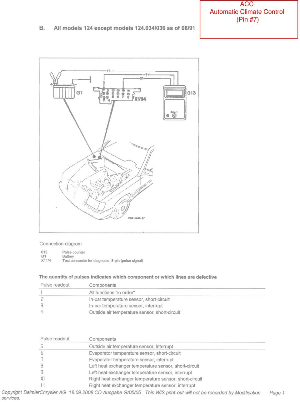
2 This document includes the complete list of s for the following systems: Pin #3 - Diagnostic Module (May only be present on models with California emissions) (WIS Group 07.51, subgroup 8.4, section 11, one page) Pin #6 - Airbag / SRS (Supplemental Restraint System) (WIS Group 91.60, subgroup 16.1, section 12, one page) - Only blink codes are available Pin #7 - ACC (Automatic Climate Control) (WIS Group 83.30, subgroup 0503, section B, four pages) - Only blink codes are available Pin #8 - HFM-SFI Fuel Injection & Digital Ignition System (WIS Group 07.51, subgroup 1.1, section 11, seven pages) Pin #9 - Roll Bar (Cabriolet only) (WIS Group 91.59, subgroup 19.1, section 12, one page) - Only blink codes are available Pin #14 - CC/ISC (Cruise Control / Idle Speed Control) For models without ASR traction control (WIS Group 30.21, subgroup 7.3, section 11, two pages) Pin #14 - EA/CC/ISC (Electronic Accelerator / CC / ISC) For models with ASR traction control (WIS Group 30.20, subgroup 6.4, section 11, two pages) CST / RB (Cabriolet Soft Top / Roll Bar) Not tested at 16-pin connector see diagram (WIS Group 77.39, subgroup 11.1, section 12, two pages) - Only blink codes are available
 - Only blink codes are available Pin #8 - HFM-SFI Fuel Injection & Digital Ignition System (WIS Group 07.51, subgroup 1.")
3

4 Preparation for recalling diagnostic trouble code () memory 1. Connect impulse counter scan tool and adaptor for impulse counter to test connection for diagnosis (X11/4) according to connection diagram (see section 0). Note: Connect impulse counter scan tool as follows: 2. Recall control modules' diagnostic trouble code memory and clear stored trouble codes (see section 0). Note The retained diagnostic trouble code () memory feature of the diagnostic module has been replaced with memory which is cleared red wire to socket 16, after disconnecting the vehicle's battery (DM voltage supply). black wire to socket 1 and In addition, the readout 1" (no malfunction in system) does not yellow wire to: appear after clearing the memory (disconnecting the vehicle's battery). readout 1" only reappears during the vehicle's Diagnostic module socket 3 subsequent trip after the diagnostic module has confirmed that all Engine control module socket 8 monitored systems and their respective components are ok EA/CC/ISC control module socket 14 (no malfunctions). Special Tools Diagnostic Trouble Code () Readout, Diagnostic Module Diagnostic Trouble Possible Cause Remedy/Test Step Code () 1 No malfunction in systems monitored - 2 Heated oxygen sensor inoperative Test HFM-SFI, Engines Vol.2, section 1. 3 Lambda control inoperative Test HFM-SFI, Engines Vol.2, section 1. 4 Air injection inoperative Test HFM-SFI, Engines Vol.2, section 1. 5 Exhaust gas recirculation inoperative Test HFM-SFI, Engines Vol.2, section 1. 6 Idle speed control inoperative Test EA/CC/ISC, sections 6/7. 7 Ignition system defective Test HFM-SFI, Engines Vol.2, section 1. 8 Engine coolant temperature sensor, open/short circuit Test HFM-SFI, Engines Vol.2, section 1. 9 Intake air temperature sensor, open/short circuit Test HFM-SFI, Engines Vol.2, section Voltage at hot wire mass air flow sensor too high/low Test HFM-SFI, Engines Vol.2, section TN-signal (rpm) at engine control module (N3/4) defective Test HFM-SFI, Engines Vol.2, section Heated oxygen sensor heater, open/short circuit Test HFM-SFI, Engines Vol.2, section Wide open throttle information defective Test EA/CC/ISC, sections 6/7. Diagnostic Trouble Possible Cause Remedy/Test Step Code () 16 Closed throttle position information defective Test EA/CC/ISC, section 6/7. 17 Data exchange malfunction between individual control modules Adjustable camshaft timing solenoid, open/short circuit Test HFM-SFI, Engines, Vol. 2, section Fuel injectors open/short circuit or Test HFM-SFI and reset engine control module adaptation self-adaptation in engine control module (N3/4) at limit to mean value, Engines, Vol. 2, section 1 Speed signal not present Test HFM-SFI, Engines, Vol. 2, section 1 Purge switchover valve, open/short circuit Test HFM-SFI, Engines, Vol. 2, section 1 Camshaft position sensor signal defective Test HFM-SFI, Engines, Vol. 2, section 1 Intake manifold pressure (in base module pressure sensor- B5/2) with engine running too low/high Starter ring gear segments and/or crankshaft position sensor defective Test HFM-SFI, Engines, Vol. 2, section 1 Knock sensors or engine control module defective Test HFM-SFI, Engines, Vol. 2, section 1 Upshift delay defective Test HFM-SFI, Engines, Vol. 2, section 1 Not used - Engine coolant temperature sensor (coolant temperature change monitor) Test HFM-SFI, Engines, Vol. 2, section 1 Copyright Daimler AG 11/4/08 G/06/08. This WIS printout will not be recorded by the update service. Page 1
 memory feature of the diagnostic module has been replaced with memory which is cleared red wire to socket 16, after disconnecting the vehicle's battery")
5 (driver-side or driver/passenger-side airbag) Preliminary work: Diagnosis - Function Test 11 Preparation for readout Fuses O.K. Connect impulse counter scan tool to data link connector (X11/4) according to connection diagram (see section 0). 8 or 16-pole connector: yellow wire to socket 6 38-pole connector: yellow wire to socket 30 The 10-pole SRS test connection (X11/13) must be connected for. Special Tools Pulse counter Adapter (driver-side or driver/passenger-side airbag) Diagnostic trouble code () No fault recognized in system - SRS control module (N2/2) Driver airbag squib (R12/3) , 9.0 Front passenger airbag squibs (R12/4, R12/5) , 10.0 Left front seat belt buckle switch (S68/3) Right front seat belt buckle switch (S68/4) Front passenger airbag resistance Voltage supply circuit 15R SRS malfunction indicator lamp (A1e15) or time limit for readout /erasing exceeded ) SRS control module (N2/2) N2/2 (SMS, Job No ) 2) indicates that the airbag deployment stage was activated in the control module. This can not be erased. The control module must be replaced. IMPORTANT NOTE! Before replacing the SRS control module (N2/2) in cases of connection. without an airbag deployment, reposition airbag harness ground connections to lowest terminal Note: The ETR's are not included in the readout, if and/or can not be erased, see ETR Test and 2.0. Copyright Daimler AG 11/4/08 G/06/08. This WIS printout will not be recorded by the update service. Page 1
 Diagnostic trouble code () No fault recognized in system - SRS control module")
6
7

8

9

10 Preliminary work: Engine Test, Adjustment, Engines, Volume 1 Note regarding diagnostic trouble code () readout: The engine control module (N3/4) for the HFM-SFI system is equipped with diagnostic trouble code () memory. Malfunctions are recognized and stored as trouble codes and are distinguished as follows: Malfunctions which are constantly present, Malfunctions which occur longer than 3 seconds, Intermittent contact malfunctions which have occured 5 during a trip. The memory remains active even if the vehicle's battery is disconnected. Malfunctions which are no longer present, are automatically erased again after a maximum of 19 trips. A trip has occured if: Vehicle speed >4 km/h (2.5 mph), Engine speed >700 rpm, Engine shut off for 30 seconds. The stored diagnostic trouble codes (s) can be read at the data link connector (X11/4) with the ignition switched ON or with the engine running. Diagnosis via an on-off ratio readout has been eliminated. Note regarding mixture preparation self-adaptation: The Lambda control system determines fuel injection duration precisely so that the fuel/air ratio is kept constant at Lambda level 1 (equals 14.7 kg air to 1 kg fuel) under all operating conditions. Should malfunctions occur in the form of: Intake air leaks, Injector wear or carbon build-up, Engine wear, Contact resistance in MAF sensor, Defective diaphragm pressure regulator, Defective purge control valve, the engine control module automatically performs a mixture adjustment. The degree of correction is calculated constantly and stored permanently. The self-adaptation is performed at idle and under partial load. Maximum correction towards rich or lean is 25%. After repair work is performed, the engine control module will automatically adapt itself again after approx. 10 trips. After eliminating a malfunction or after trial installation of an engine control module from another vehicle, the self-adaptation feature must be reset to its mean value (see Resetting and Reactivating Engine Control Module Memory" 11/5). Note regarding automatic recognition of vehicle equipment and/or Note regarding version coding on vehicles as of 03/94 (as of HHT version on vehicles up to 02/94 (up to HHT Diagnosis Version 42): Diagnosis Version 45): The engine control module recognizes and stores the following equipment The engine control module is equipped with a version coding feature as of and/or version information during the vehicle's initial operation: 03/94. The coding must be performed with the Hand-Held Tester (automatically or manually, see Notes for HHT 11/4) upon installation of a Catalytic converter/non-cataytic converter, new control module. Manual/automatic transmission, The following vehicle version data must be determined for coding: 4-Speed/5-speed automatic transmission, Cruise control, Vehicle model, Electronic accelerator, Catalytic converter (TWC), version. Non-catalytic converter (non-twc), 5-speed manual transmission, After replacing the engine control module or after trial installation of an engine 4-speed automatic transmission, control module from another vehicle, the stored data must be erased and the 5-speed automatic transmission, recognition feature reactivated (see Resetting and Reactivating Engine Cruise control (CC), Control Module Memory" 11/5). Acceleration slip regulation (ASR), Electronic traction system (ETS), Initial programming of engine control module. Country version. Prerequisite for initial programming process: Battery voltage 11 Volt minimum Vehicle speed signal V = 0 Engine rpm signal n = 0 Transmission range P/N = 1 Idle speed contact closed CTP = 1 (Caution: Vehicle can not be moved during initial programming process) Drive vehicle V = > 5 km/h (3 mph) (Only then will the transmission version be recognized). Copyright Daimler AG 11/4/08 G/06/08. This WIS printout will not be recorded by the update service. Page 1

11 Note regarding drive authorization system (DAS): Up to the end of model year 1995, a starter lock-out system is installed which interrupts circuit 50 to the starter. Additionally, the code number and VIN must be entered (see HHT actual values DAS", menu selection 3/6). On vehicles starting model year 1996 (HHT Diagnosis Version 46), the RCL system is enhanced with a so-called drive authorization system stage 2. The activation of the drive authorization system (DAS) is initiated by the RCL control module and transmitted to the engine control module via the CAN data bus. After activation of the drive authorization system (DAS), the fuel injection system is rendered inoperative by the engine control module. The drive authorization system (DAS) can be activated or deactivated with the infrared remote control transmitter or the master key. The engine control module and RCL control module are permanently locked with one another by an identification code. This identification code can not be erased (see HHT actual values DAS menu selection 3/6). Therefore, trial installation of an engine control module or RCL control module from another vehicle is no longer possible. CAUTION! If a new engine control module is installed for test purposes only, a maximum of 40 engine starts can be performed before the control modules are permanently locked with one another. After 40 engine starts, the engine control module can no longer be used in any other vehicle. Notes for HHT Version coding with HHT as of 03/94 (as of HHT Diagnosis Version Fault search with HHT 45). Diagnostic trouble code () memory: Select Current 's". a) Before replacement of the engine control module, the existing code If the actual condition changes, e.g. when wiggling a connector, the number must be read and stored with the HHT (menu selection 6 Version coding"). After installation of the new control module, the change is reported optically and acoustically so that troubleshooting can previously read code number must be entered. be performed directly with the HHT. Note: Loose connections If returning a new control module to a PDC, the code number must Loose connections are stored if they occur several times in a certain be erased. time period. Therefore, they can appear only as Stored 's" and never as Current 's". b) If the code number can not be read, the vehicle equipment/version must be determined, the corresponding code number obtained from Nominal values the Spare Parts Microfiche, Group 54 and manually entered with the All nominal values relative to the actual values shown on the HHT are HHT. listed in the Diagnostic Manual, Engines, Volume 1, section A. c) When performing a trial installation of a control module with the Actual values for engine coolant temperature, intake air same part number from another vehicle (to end of model year temperature and air mass 1995), but with a different code number, the following must be In case of an open or short circuit, the actual value is immediately observed: replaced by a substitute value which is very close to the actual value. Read and record code number from vehicle with complaint. Therefore, a fault can not be recognized clearly. A readout of the fault is Exchange control modules. Read and record code number from the exchanged control possible only via the diagnostic trouble code () memory. module. Actual value for engine rpm Enter the code number from the original control module into the In case of the engine rpm's, the HHT display indicates the closed exchange control module. throttle (idle) speed nominal value calculated by the control module on Perform function test. Before returning control module to other vehicle, enter recorded the left and on the right, the rpm actual value. Both values should differ code number into exchange control module. from each other only slightly. The permissible tolerances are not yet Exchange control modules. determined. Copyright Daimler AG 11/4/08 G/06/08. This WIS printout will not be recorded by the update service. Page 2
 is initiated by the RCL control module and transmitted to the engine control module via the CAN data bus.")
12 Notes for HHT (continued) Clearing Diagnostic Trouble Code () Memory a) Press start button for 2 to 4 seconds ( appears). Drive authorization system (DAS) b) Press start button for 6 to 8 seconds, thereby clearing the previously Upon replacement the engine control module must be version coded displayed malfunction () from memory. using the HHT. Additionally, the code number and VIN must be entered c) Repeat steps a) and b) until the number " appears (no malfunctions (see HHT nominal values DAS", menu selection 3/6). stored). Resetting and Reactivating Engine Control Module Memory Preparation for Test with Impulse Counter Scan Tool a) Clear diagnostic trouble code () memory. Note: b) After the number " appears, press start button for 6 to 8 seconds. The memory readout, memory clearing as well as resetting c) Switch ignition OFF and wait a minimum of 2 seconds. and reactivating the engine control module can be performed with the d) Turn ignition ON, wait a minimum of 10 seconds and then start engine. impulse counter scan tool only on vehicles up to HHT Diagnosis Version 46. On vehicles as of HHT Diagnosis Version 49, it is possible only with Note: the HHT. Control modules manufactured by Bosch up to 8/93, the start button must be Connect impulse counter scan tool to data link connector (X11/4) pressed 5 to 6 seconds to clear the memory and 8 to 9 seconds to according to connection diagram. reset and reactivate the engine control module memory. Reading Diagnostic Trouble Code () Memory a) Ignition: ON b) Press start button for 2 to 4 seconds. c) Read and record. d) Press start button again. e) Read and record. Repeat steps d) and e) until the first reappears. Special Tools Connection Diagram - Impulse Counter Scan Tool/ Hand-Held Tester (HHT) Model 124 Impulse counter scan tool Black wire circuit 31 (ground) Socket 1 Red wire circuit 15 (ignition) Socket 16 Hand-Held Tester (HHT) Black wire circuit 31 (ground) Socket 1 White wire circuit 15 (ignition) Socket 16 Red wire circuit 30 Battery + or X4/10 Connect yellow wire of impulse counter scan tool/ Hand-Held Tester (HHT) as follows: Engine control module Socket 8 EA/CC/ISC control module Socket 14 Diagnostic module Socket 3 Figure Impulse counter scan tool (Hand-Held Tester 087 optional) 087 Hand-Held Tester (Impulse counter scan tool 013 optional) X11/4 Data link connector ( readout) (16-pole) P A Copyright Daimler AG 11/4/08 G/06/08. This WIS printout will not be recorded by the update service. Page 3
 Repeat steps a) and b) until the number \" appears (no malfunctions (see HHT nominal values DAS\", menu selection 3/6). stored).")
13 Connection Diagram - Impulse Counter Scan Tool/ Hand-Held Tester (HHT) Models 129, 140, 202 and 210 Note: The memory can be read with the impulse counter scan tool only on vehicles up to HHT diagnosis code 46. On vehicles starting HHT diagnosis code 49 it can be read only with the HHT. Connect red wire of Impulse counter scan tool to socket 3, black wire of impulse counter scan tool to socket 1, and connect yellow wire as follows: Engine control module (HFM-SFI) Socket 4 EA/CC/ISC control module Socket 7 Base module (except models 202, 210) Socket 8 Rpm signal (TN output, except models 202, 210) Socket 13 Rpm signal (TN output, model 202, 210) Socket 17 Diagnostic module Socket 19 Figure Impulse counter scan tool (Hand-Held Tester 087 optional) 075 Impulse counter scan tool adapter 087 Hand-Held Tester U (Impulse counter scan tool 013 optional) 094 Multiplexer X11/4 Data link connector ( readout) (38-pole) - No malfunction in system - ECT sensor (B11/3) short circuit ECT sensor (B11/3) open circuit ECT sensor (B11/3) implausible ECT sensor (B11/3) intermittent contact Contacts in connector of B11/3 or N3/4. IAT sensor (B1 short circuit IAT sensor (B1 open circuit IAT sensor (B1 intermittent contact Contacts in connector of B17 or N3/4. Hot film MAF sensor (B2/5) air flow implausibly high Engine friction excessive. Hot film MAF sensor (B2/5) open circuit CTP switch (M16/1s2 or M16/2s2) throttle valve angle implausibly large CTP switch (M16/1s2 or M16/2s2) air flow implausibly high CTP switch (M16/1s2 or M16/2s2) intermittent contact Only possible up to end of model year ISC system at lower control stop Intake air leak, throttle body binding, CC or EA operating in limp-home" mode. ISC system at upper control stop Intake air leak, throttle body binding, CC or EA operating in limp-home" mode. CC or EA indicates limp-home" mode Intake air leak, throttle body binding, adjust throttle linkage, erase 's in HFM- SFI control module. 2) O2S 1 (before TWC) (G3/2) sensor voltage too high ) O2S 1 (before TWC) (G3/2) cold or open circuit ) O2S 1 (before TWC) (G3/2) sensor voltage implausible Except model O2S 2 (after TWC) (G3/ sensor voltage too high Copyright Daimler AG 11/4/08 G/06/08. This WIS printout will not be recorded by the update service. Page 4
 Socket 8 Rpm signal (TN output, except models 202, 210) Socket 13 Rpm signal (TN output, model 202, 210) Socket 17 Diagnostic module")
14 Except model 124 O2S 2 (after TWC) (G3/ cold or open circuit Except model 124 O2S 2 (after TWC) (G3/ sensor voltage implausible ) The " can be displayed up to 12/92 even if no fault exists. Only possible up to end of model year O2S 1 (before TWC) heater (G3/2) current too low O2S 1 (before TWC) heater (G3/2) current too high O2S 1 (before TWC) heater (G3/2) short circuit Except model 124 O2S 2 (after TWC) heater (G3/ current too low Except model 124 O2S 2 (after TWC) heater (G3/ current too high Except model 124 O2S 2 (after TWC) heater (G3/ short circuit O2S system operating at rich limit, mixture too lean O2S system operating at lean limit, mixture too rich Injector (Y62y, cylinder 1 short circuit to plus Injector (Y62y, cylinder 1 open/short circuit to ground Injector (Y62y2), cylinder 2 short circuit to plus Injector (Y62y2), cylinder 2 open/short circuit to ground Intake air leak, fuel injectors, diaphragm pressure regulator. Intake air leak, fuel injectors, diaphragm pressure regulator Only possible up to end of model year Injector (Y62y3), cylinder 3 short circuit to plus Injector (Y62y3), cylinder 3 open/short circuit to ground Injector (Y62y4), cylinder 4 short circuit to plus Injector (Y62y4), cylinder 4 open/short circuit to ground Injector (Y62y5), cylinder 5 short circuit to plus Injector (Y62y5), cylinder 5 open/short circuit to ground Injector (Y62y6), cylinder 6 short circuit to plus Injector (Y62y6), cylinder 6 open/short circuit to ground Self-adaptation at idle speed too rich Self-adaptation at idle speed too lean Intake air leak, fuel injectors, diaphragm pressure regulator, engine wear (reset self-adaptation following repair, see 11/5). Intake air leak, fuel injectors, diaphragm pressure regulator, engine wear (reset self-adaptation following repair, see 11/5). Only possible up to end of model year Self-adaptation at lower partial load too rich Intake air leak, fuel injectors, diaphragm pressure regulator, engine wear (reset self-adaptation following repair, see 11/5). Self-adaptation at lower partial load too lean Intake air leak, fuel injectors, diaphragm pressure regulator, engine wear (reset self-adaptation following repair, see 11/5). Self-adaptation at upper partial load too rich Intake air leak, fuel injectors, diaphragm pressure regulator, engine wear (reset self-adaptation following repair, see 11/5). Self-adaptation at upper partial load too lean Intake air leak, fuel injectors, diaphragm pressure regulator, engine wear (reset self-adaptation following repair, see 11/5). Ignition output 3 or ignition coil (T1/3) for cylinder 1 misfires , 16.0 and 19.0 Ignition output 3 or ignition coil (T1/3) for cylinder 6 misfires , 16.0 and 19.0 Copyright Daimler AG 11/4/08 G/06/08. This WIS printout will not be recorded by the update service. Page 5
 heater (G3/ current too high Except model 124 O2S 2 (after TWC) heater (G3/ short circuit O2S system operating at rich limit, mixture too lean O2S")
15 Ignition output 3 or ignition coil (T1/3) current value not obtained Ignition output 1 or ignition coil (T1/ for cylinder 2 misfires Only possible up to end of model year Ignition output 1 or ignition coil (T1/ for cylinder 5 misfires Ignition output 1 or ignition coil (T1/ current value not obtained Ignition output 2 or ignition coil (T1/2) for cylinder 3 misfires Ignition output 2 or ignition coil (T1/2) for cylinder 4 misfires Ignition output 2 or ignition coil (T1/2) current value not obtained see 11/ , 16.0 and , 14.0 and , 14.0 and , 14.0 and , 15.0 and , 15.0 and , 15.0 and 18.0 CKP sensor (L5) signal not recognized/implausible CKP sensor (L5) magnet is missing (segment control) CKP sensor (L5) number of teeth implausible (increment control) CKP sensor (L5) rpm implausibly high CMP sensor (L5/ implausible/not recognized (segment control) Camshaft Hall-effect sensor (B6/ implausible/not recognized (increment control) TN-signal output (rpm signal), short circuit to ground TN-signal output (rpm signal), short circuit to plus VSS not recognized Only possible up to end of model year VSS implausibly high FP relay module (K2 open/short circuit KS 1 (A16) open circuit KS 2 (A16) open circuit Maximum retard setting on at least one cylinder has been reached Ignition angle deviation between the individual cylinders is > 6 CKA. Knock control evaluation circuit in engine control module (N3/4) defective Momentary fault in self-adaptation of closed throttle speed/partial load Model 124, 129 and 140: AIR pump switchover valve (Y32) and/or electromagnetic AIR pump clutch (Y33), model 202: AIR pump switchover valve (Y32) and/or AIR relay module (K1 open/short circuit Purge control valve (Y58/ open/short circuit Replace knock sensors (KS). Replace knock sensors (KS). Increased tendency to knock due to poor fuel quality, combustion chamber carbon build-up or mechanical damage. Increased tendency to knock due to poor fuel quality, combustion chamber carbon build-up or mechanical damage. N3/4. Momentary malfunction in fuel mixture preparation Only possible up to end of model year Purge control valve (Y58/ short circuit to plus Upshift delay switchover valve (Y3/3) open/short circuit Adjustable camshaft timing solenoid (Y49) short circuit to plus Adjustable camshaft timing solenoid (Y49) open/short circuit to ground EGR switchover valve (Y2 short circuit to plus EGR switchover valve (Y2 open/short circuit to ground Transmission overload protection switch (S65) short circuit to ground Transmission overload protection switch (S65) closed and 2nd gear recognized Transmission overload protection switch (S65) open and 2nd gear recognized Transmission overload protection switch (S65) implausible CAN communication from engine control module (N3/4) defective CAN communication from ASR control module (N30/ defective CAN communication from EA/CC/ISC control module (N4/ or CC/ISC control Copyright Daimler AG 11/4/08 G/06/08. This module WIS printout (N4/3) will defective not be recorded by the update service. Page 6

16 CAN communication from diagnostic module (OBD II) (N59/ defective Starter signal (circuit 50) not present Only possible up to end of model year ) 5) 5) 5) 6) 6) Fuel safety shut-off of electronic accelerator or cruise control active Resonance intake manifold switchover valve (Y22/6) short circuit to plus Resonance intake manifold switchover valve (Y22/6) open/short circuit to ground Control of ignition coil preloading voltage exceeds limits O2S 2 (after TWC) heater relay module (K35) short circuit to plus O2S 2 (after TWC) heater relay module (K35) open/short circuit to ground Voltage supply circuit 87 U at engine control module (N3/4) implausible Voltage supply circuit 87 U at engine control module (N3/4) low voltage Engine control module (N3/4) Engine control module (N3/4) not coded Engine control module identification of N3/4 faulty Engine control module code bytes of N3/4 faulty CAN communication from RCL control module (N54) faulty Engine starts with RCL system locked and 15.1 Engine control module (N3/4) N3/4. Code N3/4. Code N3/4, if necessary, replace N3/4. Code N3/4, if necessary, replace N3/ Incorrect operation, clear memory. 4) Starting 06/93 5) Starting 01/94 6) Starting model year 1996, models 140/210, the can be displayed from 09/95 and up to 11/95, even if no fault exists. Only possible up to end of model year Engine control module (N3/4) N3/4 ISC and CC/ISC actuators interchanged Engine control module (N3/4) N3/4 Engine control module (N3/4) N3/4 Replace actuator EA/CC/ISC or CC/ISC actuator Perform learning process on engine control module with HHT. If the fault is still present, replace actuator. Engine control module (N3/4) N3/4 Engine control module (N3/4) N3/4 EA/CC/ISC or CC/ISC actuator Perform learning process on engine control module with HHT. If the fault is still present, replace actuator. - Not applicable for U.S.A. version vehicles Engine control module (N3/4) N3/4 Engine control module (N3/4) N3/4 Copyright Daimler AG 11/4/08 G/06/08. This WIS printout will not be recorded by the update service. Page 7
 open/short circuit to ground Voltage supply circuit 87 U at engine control module (N3/4) implausible Voltage supply circuit 87 U at engine control module (N3/4) low voltage Engine")
17 To Read Diagnostic Trouble Codes Connect impulse counter (yellow wire to socket 9) as shown in section 0. Ignition: ON, Roll bar malfunction indicator lamp comes on. Special Tools No diagnostic trouble codes () stored in memory. - - Roll bar control module (N53) Roll bar control module (N53), voltage supply Roll bar deployment solenoid (Y57/, open circuit, short to circuit 30 or Rear axle switch (S83/2 or S83/3) short to circuit 30 or Roll bar malfunction indicator lamp (E30) Copyright Daimler AG 11/4/08 G/06/08. This WIS printout will not be recorded by the update service. Page 1
 short to circuit 30 or 31. 23 4.")
18 Diagnosis - Diagnostic Trouble Code () Readout Preparation for Readout Note concerning Electronic Traction System (ETS) adaptation (only Connect impulse counter scan tool and/or HHT to data link connector model 202, as of 06/94) (X11/4) according to connection diagram (see section 0). If the CC/ISC control module (N4/3) is replaced, or if a control module from Model 124: yellow wire to socket 14 another vehicle is temporarily installed, the ETS adaptation must be activated. Models 129, 140, 202: yellow wire to socket 7 Thereby allowing the CC/ISC control module to adapt to the vehicle configuration, ie: with ETS or ABS only. Model 210: HHT ETS Adaptation 1. Ignition: ON 2. Wait 3 seconds 3. Engine: Start 4. Wait seven seconds 5. Ignition: OFF Absolutely required. 6. Ignition: ON Diagnosis - Diagnostic Trouble Code () Readout Special Tools No fault in system - CC/ISC control module (N4/3) N4/3 Closed throttle position switch (M16/3s2) Stop lamp switch (S9/ Cruise control switch (S40) OFF CC/ISC control module (N4/3) N4/3 Actual value potentiometer , 5.0 Starter lock-out/back-up lamp switch (S16/3) (transmission range recognition) Engine speed (TN) signal Vehicle speed signal (VSS) Safety relay within CC/ISC control module (N4/3) N4/3 CC/ISC control module (N4/3) N4/3 Engine harness Check harness wire insulation. Conditions for activation of CC/ISC actuator (M16/2) not fulfilled. Conditions: Engine: OFF Transmission range: P/N CC/ISC actuator (M16/2) Throttle valve actual value potentiometer (M16/2r Drive actual value potentiometer (M16/2r2) Safety contact switch (M16/2s , 8.0 CTP switch recognition (M16/2s2) Potentiometer voltage supply Reset not accomplished (actuator adaptation) Erase : Ignition: OFF Ignition: ON (for at least 90 seconds) If reappears: CC/ISC actuator (M16/2) CC switch (S40) Stop lamp switch (S9/ Copyright Daimler AG 11/4/08 G/06/08. This WIS printout will not be recorded by the update service Page 1

19 Not valid for U.S. vehicles CAN databus: Message from CC/ISC control module (N4/3) faulty N4/3 Reception from engine control module (N3/4) faulty Left front axle VSS sensor (L6/ from ABS (N30) or ETS/SPS (N47-2) control module Rear axle VSS sensor (L6) from ABS control module (N30) Left rear axle VSS sensor (L6/3) from ETS/SPS control module (N47-2) Incorrect CC/ISC control module (N4/3) installed N4/3 ETS signal Engine speed signal (TN) from engine control module (N3/4) Fuel safety shut-off signal to engine control module (N3/4) Copyright Daimler AG 11/4/08 G/06/08. This WIS printout will not be recorded by the update service. Page 2
 installed N4/3 ETS signal Engine speed signal (TN) from engine control module (N3/4) Fuel safety shut-off signal to engine control module (N3/4) 23 14.0 23 15.")
20 Preparation for Readout Connect impulse counter scan tool and/or HHT to data link connector (X11/4) according to connection diagram (see section 0). Model 124: yellow wire to socket 14 Models 129, 140, 202: yellow wire to socket 7 Model 210: Only possible with HHT. Note: The Test Program is divided into two sections: Electronic accelerator with ISC Cruise control According to the diagnosis made, troubleshoot by performing only the related test steps in the particular group. Special Tools No fault in system - EA/CC/ISC control module (N4/ N4/1 Safety contact switch (M16/1s , 6.0 Stop lamp switch (S9/ Safety contact switch (M16/1s Cruise control switch (S40) OFF EA/CC/ISC control module (N4/ N4/1 Actual value potentiometer (M16/1r2) Starter lock-out/back-up lamp switch (S16/3) (transmission range recognition) , Closed throttle position switch (S29/3) Engine speed (TNA) signal Vehicle speed signal (VSS) , 16.0 Safety relay within EA/CC/ISC control module (N4/ N4/1 EA/CC/ISC control module (N4/ N4/1 Engine harness Check harness wire insulation. Conditions for activation of EA/CC/ISC actuator (M16/ not fulfilled. Conditions: Engine: OFF Transmission range: P/N EA/CC/ISC actuator (M16/ Reference potentiometer (M16/1r (voltage supply) Reference potentiometer (M16/3r Actual value potentiometer (M16/3r2) Safety contact switch (M16/3s Closed throttle position switch (M16/1s2) Actuator motor (M16/1m Magnetic clutch (M16/1k Reset not accomplished (actuator adaptation) CC switch (S40) Stop lamp switch (S9/ Starter lock-out/backup lamp switch (S16/ Not applicable to U.S. version vehicles , , Erase : Ignition: OFF Ignition: ON (for at least 90 seconds). If reappears: EA/CC/ISC actuator (M16/ , Copyright Daimler AG 11/4/08 G/06/08. This WIS printout will not be recorded by the update service. Page 1

21 CAN databus: Message from EA/CC/ISC control module (N4/ faulty N4/1 Reception from engine control module (N3/4) faulty Left front axle VSS (L6/ from ASR control module (N30/ Models 129, 140, 202, 210: Left rear axle VSS (L6/3) from ASR control module (N30/ Model 124: Hall-effect speed sensor (B6) Engine speed signal (TN) from engine control module (N3/4) Fuel safety shut-off signal to engine control module (N3/4) Closed throttle recognition signal to engine control module (N3/4) CTP switch (S29/3) CAN databus: data exchange with ASR control module (N30/ implausible ASR control module (N30/ Copyright Daimler AG 11/4/08 G/06/08. This WIS printout will not be recorded by the update service. Page 2
22 Preliminary work: Diagnosis - Function Test 11 Read out Diagnostic Trouble Codes, see section 0 Special Tools Diagnosis Limit switch diagnostic trouble codes ('s) are only stored when the soft top stops moving during soft top operation and the switch is held depressed until the indicator lamp begins blinking. The exceptions are the switches for roll bar extended and roll bar retracted where the indicator lamp in the roll bar switch lights. 's 5-16 are considered limit switch 's, which do not necessarily mean the respective switch is defective, but rather should be interpreted as an indication of which limit switch signals are absent and are needed for the sequence to continue. s: Electrical fault (the last soft top or roll bar movement requested was completed). Hydraulic fault (the last soft top or roll bar movement requested, did not occur). Connection Diagram - Impulse Counter Scan Tool Connect to socket 2 of X11/12 located in right front passenger footwell. To avoid need for extension cable (010), connect black lead of impulse counter scan tool to good ground and red lead to X4/10 inside vehicle interior. Figure Extension cable 013 Impulse counter scan tool X4/10 Terminal block (circuit 30/circuit 61 battery) X11/4 Data link connector ( readout) X11/12 Power soft top test connector (4-pole) X11/13 SRS test connector (10-pole) Diagnostic trouble code () No 's stored. - Low voltage Normal operating time exceeded Illogical limit switch signals 24 Soft top compartment cover locked" switch (A25/1s2) Soft top compartment cover closed" switch (A25/1s Soft top storage compartment open" switch (S84/5) Soft top fabric bow locked" switch (S84/8) Soft top fabric bow down" switch (S84/ Soft top fabric bow raised" switch (S84/6) Left front soft top locked" switch (S84/ Right front soft top locked" switch (S84/2) Soft top open" switch (soft top in storage compartment) (S84/3) Soft top overhead" switch (S84/4) RB retracted" switch (S83/5) Copyright Daimler AG 11/4/08 G/06/08. This WIS printout will not be recorded by the update service. Page 1
23 Diagnostic trouble code () RB extended" switch (S83/6) Automatic deployment of roll bar has occurred Power soft top switch (S84) Vehicle speed signal Circuit in control module (N52), solenoid valve, roll bar retracted N52 Circuit in CST/RB hydraulic unit (A7/5), circuit in RB rod side valve (Y57y10) , 21.0 Circuit in control module (N52), solenoid valve, roll bar extended N52 Circuit in RB piston side valve (Y57y1 Circuit in control module (N52), power windows 23 N Copyright Daimler AG 11/4/08 G/06/08. This WIS printout will not be recorded by the update service. Page 2
W140 Diagnostic Trouble Codes (DTC) Models with M119 Engine Only!
 Models with M119 Engine Only!") W140 Diagnostic Trouble Codes (DTC) Models with M119 Engine Only! The pages in this document have the Diagnostic Trouble Codes (DTC s) for the following models, all of which have M119 V8 engines with LH-SFI
W140 Diagnostic Trouble Codes (DTC) Models with M119 Engine Only! The pages in this document have the Diagnostic Trouble Codes (DTC s) for the following models, all of which have M119 V8 engines with LH-SFI
Electronic Power Control
 Service. Self-Study Programme 210 Electronic Power Control Design and Function With the Electronic Power Control system, the throttle valve is actuated only by an electric motor. This eliminates the need
Technical Service Information
 Technical Service Information COMPLAINT: CAUSE: 1996-20 DEFINITIONS When a VW/Audi vehicle is exhibiting a symptom or is in fail-safe, the technician, in many cases, is unable to communicate with the on-board
E - THEORY/OPERATION
 E - THEORY/OPERATION 1995 Volvo 850 1995 ENGINE PERFORMANCE Volvo - Theory & Operation 850 INTRODUCTION This article covers basic description and operation of engine performance-related systems and components.
SAS light Check Engine Malfunction Indicator Lamp
 SAS light Check Engine Malfunction Indicator Lamp Here's how to do it: In car ECM Diagnostics/ECM Reset procedure: 1) Sit in the driver's seat. 2) Turn the ignition key to the ON position and wait three
Powertrain DTC Summaries EOBD
 Powertrain DTC Summaries Quick Reference Diagnostic Guide Jaguar XJ Range V6, V8 N/A and V8 SC 2003.5 Model Year Refer to pages 2 9 for important information regarding the use of Powertrain DTC Summaries.
Automotive Sensor Simulator. Automotive sensor simulator. Operating manual. AutoSim
 Automotive sensor simulator Operating manual AutoSim Contents Introduction.. page 3 Technical specifications.... page 4 Typical application of AutoSim simulator..... page 4 Device appearance... page 5
Fault Code Manual for Mercedes-Benz Analog Systems 1988-1997 Digital Systems 1993-2000
 Fault Code Manual for Mercedes-Benz Analog Systems 1988-1997 Digital Systems 1993-2000 Baum Tools Unlimited Inc. February 1, 2001 Table of Contents The Diagnostic Process Information Gathering... 4 Diagnostic
Air conditioning, electrical testing
 just a test. Air conditioning, electrical testing 01-253 Wire and component test using VAG1598 A test box Special tools and equipment VAG 1598 A test box and VAG 1598/11 adapter cable and VAG 1598/12 VAG1526
Powertrain DTC (P000-P0999) for EOBD Vehicles (Directive 98/69/EC of the European Parliament)
 for EOBD Vehicles (Directive 98/69/EC of the European Parliament)") Powertrain DTC (P000-P0999) for EOBD Vehicles (Directive 98/69/EC of the European Parliament) 1 Trouble Fault location Probable cause code 1 P0000 No fault found - P0001 Fuel volume regulator control -
Powertrain DTC (P000-P0999) for EOBD Vehicles (Directive 98/69/EC of the European Parliament) 1 Trouble Fault location Probable cause code 1 P0000 No fault found - P0001 Fuel volume regulator control -
ENGINE DIAGNOSTICS & CONTROL
 ENGINE DIAGNOSTICS & CONTROL CONTROL SYSTEM WIRING DIAGRAM Page 1 Page 2 MONITORING SYSTEM AND CONTROL SYSTEM DEVICE RELATIONSHIP CHART : Applicable Component Input Battery Ignition switch A/C switch,
Electronic Diesel Control EDC 16
 Service. Self-Study Programme 304 Electronic Diesel Control EDC 16 Design and Function The new EDC 16 engine management system from Bosch has its debut in the V10-TDI- and R5-TDI-engines. Increasing demands
ON-Board Diagnostic Trouble Codes
 ON-Board Diagnostic Trouble Codes The list below contains standard diagnostic trouble codes (DTC s) that are used by some manufacturers to identify vehicle problems. The codes provide below are generic
INSTRUMENT PANEL. 1995 Volvo 850 DESCRIPTION & OPERATION. 1995-96 ACCESSORIES & EQUIPMENT Volvo Instrument Panels
 INSTRUMENT PANEL 1995 Volvo 850 1995-96 ACCESSORIES & EQUIPMENT Volvo Instrument Panels 850 WARNING: When working around steering column and before performing repairs, disconnect and shield battery ground
Signature and ISX CM870 Electronics
 Signature and ISX CM870 Electronics Cummins West Training Center System Description General Information The Signature and ISX CM870 engine control system is an electronically operated fuel control system
PROCEDURES FOR SELF DIAGNOSTICS
 PROCEDURES FOR SELF DIAGNOSTICS Baum Tools Unlimited Inc. March 31, 1999 TAU 2.1 READING ACTUAL VALUES 1. Remove the operating console from the TAU 2. At the upper side of the operating consol there is
B Test and Adjustment Jobs Engines 104, 119, 120 LH-SFI
 Listing of Test Steps 1 Test equipment......................................... connect/disconnect. 2.0 Throttle control linkage.................................... check throttle valve for free movement
DTC Summaries. V8 AJ26 Engine Management 1997. Refer to page 2 for important information regarding the use of this Summary.
 DTC Summaries V8 AJ26 Engine Management 1997 OBD II MONITORING CONDITIONS: When testing for DTC reoccurrence, it can be determined if the Service Drive Cycle was of sufficient length by performing a PDU
Evaporative emissions system
 just a test. Evaporative emissions system 20-48 Function description of EVAP canister system Depending upon the air pressure and ambient temperature, fuel vapor will form above the level of fuel in the
LAND ROVER FUEL INJECTION SYSTEMS
 LAND ROVER FUEL INJECTION SYSTEMS INTRODUCTION Land Rover vehicles use one of two types of electronically controlled fuel injection systems: Multiport Fuel Injection (MFI) or Sequential Multiport Fuel
Electronically Controlled Air Suspension (ECAS) for Trucks
 for Trucks") $2.50 Electronically Controlled Air Suspension (ECAS) for Trucks Maintenance Manual No. 36 Issued 7-99 ECAS System for 6 x 2 and 6 x 4 Vehicles with Rear Air Suspensions Service Notes Service Notes This
$2.50 Electronically Controlled Air Suspension (ECAS) for Trucks Maintenance Manual No. 36 Issued 7-99 ECAS System for 6 x 2 and 6 x 4 Vehicles with Rear Air Suspensions Service Notes Service Notes This
TOYOTA ELECTRONIC TRANSMISSION CHECKS & DIAGNOSIS
 Checks and Adjustments The transmission requires regular maintenance intervals if it is to continue to operate without failure. As we discussed in previous sections, transmission fluid loses certain properties
DIAGNOSIS SYSTEM (3S GTE and 5S FE)
") Diagnosis System (3SGTE and 5SFE) FI39 DIAGNOSIS SYSTEM (3SGTE and 5SFE) DESCRIPTION The ECM contains a builtin, selfdiagnosis system by which troubles with the engine signal network are detected and a
Diagnosis System (3SGTE and 5SFE) FI39 DIAGNOSIS SYSTEM (3SGTE and 5SFE) DESCRIPTION The ECM contains a builtin, selfdiagnosis system by which troubles with the engine signal network are detected and a
DTC Database (OBD-II Trouble Codes)
") Auto Consulting S.a.s di Cofano A. & C. Attrezzature diagnostiche Elaborazioni elettroniche Formazione tecnica DTC Database (OBD-II Trouble Codes) Definitions for generic powertrain diagnostic trouble
Auto Consulting S.a.s di Cofano A. & C. Attrezzature diagnostiche Elaborazioni elettroniche Formazione tecnica DTC Database (OBD-II Trouble Codes) Definitions for generic powertrain diagnostic trouble
Typical ECM/PCM Inputs
 Typical ECM/PCM Inputs The computer system components fall into two categories: sensors (inputs) and controlled components (outputs). Each system has sensors. Not every system has all the ones listed,
Introduction to Electronic Signals
 Introduction to Electronic Signals Oscilloscope An oscilloscope displays voltage changes over time. Use an oscilloscope to view analog and digital signals when required during circuit diagnosis. Fig. 6-01
Meritor WABCO Pneumatic Antilock Braking System (ABS) 42.22
 42.22") (ABS) 2.22 Troubleshooting WARNING Before testing a vehicle equipped with Automatic Traction Control (ATC) on a dynamometer, the ATC system must be disabled. See Subject 160 for instructions. Activation
(ABS) 2.22 Troubleshooting WARNING Before testing a vehicle equipped with Automatic Traction Control (ATC) on a dynamometer, the ATC system must be disabled. See Subject 160 for instructions. Activation
DESCRIPTION. DTC P0351 Ignition Coil "A" Primary / Secondary Circuit. DTC P0352 Ignition Coil "B" Primary / Secondary Circuit
 1 of 10 6/4/2012 10:38 PM Last Modified: 3-27-2012 6.4 C From: 201203 Model Year: 2013 Model: FR-S Doc ID: RM000000XH40PUX Title: FA20 ENGINE CONTROL: SFI SYSTEM: P0351-P0354: Ignition Coil "A" Primary
CAUTION: CAREFULLY READ INSTRUCTIONS BEFORE PROCEEDING. NOT LEGAL FOR SALE OR USE IN CALIFORNIA OR ON ANY POLLUTION CONTROLLED VEHICLES.
 Twin Tec Installation Instructions for Twin Cam Ignition CAUTION: CAREFULLY READ INSTRUCTIONS BEFORE PROCEEDING. T LEGAL FOR SALE OR USE IN CALIFORNIA OR ON ANY POLLUTION CONTROLLED VEHICLES. OVERVIEW
Volvo Vehicle Communications Software Manual
 Volvo Vehicle Communications Software Manual August 2013 EAZ0025B47A Rev. C Trademarks Snap-on is a trademark of Snap-on Incorporated. All other marks are trademarks or registered trademarks of their respective
Introduction. In this Self-study Programme we will explain to you the design and function of the CAN data bus. SSP 186/01
 Introduction The requirements relating to driving safety, driving comfort, exhaust emissions and fuel economy are are becoming ever more stringent. This entails more intensive information exchange between
Note: This information obtained from internet sources and not verified- use at your own risk!!!!
 Cummins Engine Diagnostic Fault Codes for 2003 and later engines (generally for 2004 and later Alpines; see page 13 for earlier engine diagnostic codes): Note: This information obtained from internet sources
Model 124 Relay and Control Modules Locations. 00-B.2a
 00-B.2a Page No. Fig. No. K1/2 Overvoltage protection relay (87E/87L/30a, 9-pole) B.2/2 1 K2 Headlamp washer relay B.2/1 K3/1 Intake manifold preheater relay B.2/4 14 K5 Power seat relay B.2/1 K9 Auxiliary
Diagnostic Trouble Code (DTC) Charts
 Charts") Diagnostic Trouble Code (DTC) Charts Note: Before proceeding to the Pinpoint Test, refer to the Diagnostic Trouble Code (DTC) Descriptions for additional information to assist in diagnosis. 6.0L Diesel
Diagnostic Trouble Code (DTC) Charts Note: Before proceeding to the Pinpoint Test, refer to the Diagnostic Trouble Code (DTC) Descriptions for additional information to assist in diagnosis. 6.0L Diesel
Diagnostic Trouble Code (DTC) Charts and Descriptions
 Charts and Descriptions") 2007 PCED On Board s SECTION 4: Powertrain DTC Charts and Descriptions Procedure revision date: 03/29/2006 Trouble Code (DTC) Charts and Descriptions Note: Refer to the applicable Workshop Manual section
2007 PCED On Board s SECTION 4: Powertrain DTC Charts and Descriptions Procedure revision date: 03/29/2006 Trouble Code (DTC) Charts and Descriptions Note: Refer to the applicable Workshop Manual section
TOYOTA ELECTRONIC CONTROL TRANSMISSION
 Electronic Control Transmission (ECT) The Electronic Control Transmission is an automatic transmission which uses modern electronic control technologies to control the transmission. The transmission itself,
VEHICLE SPEED CONTROL SYSTEM
 PL VEHICLE SPEED CONTROL SYSTEM 8H - 1 VEHICLE SPEED CONTROL SYSTEM TABLE OF CONTENTS page DESCRIPTION AND SPEED CONTROL SYSTEM...1 SPEED CONTROL SERVO-PCM OUTPUT....2 SPEED CONTROL SWITCHES PCM INPUT...2
Lotus Service Notes Section EMR
 ENGINE MANAGEMENT SECTION EMR Sub-Section Page Diagnostic Trouble Code List EMR.1 3 Component Function EMR.2 7 Component Location EMR.3 9 Diagnostic Guide EMR.4 11 CAN Bus Diagnostics; Lotus TechCentre
Important: Always perform the Diagnostic System Check - Vehicle prior to using this diagnostic procedure. P0106, P0107 P0107
 Page 1 of 5 DTC P0106 DTC Descriptor 2006 Pontiac GTO GTO (VIN V) Service Manual Document ID: 1417869 DTC P0106: Manifold Absolute Pressure (MAP) Sensor Diagnostic Fault Information Important: Always perform
VAG VW AUDI SEAT SKODA
 VAG VW AUDI SEAT SKODA Diagnostic Trouble Code (DTC) Definitions The following Diagnostic Trouble Code (DTC) definitions lists provide both VAG and SAE (OBD-II) trouble codes. For codes not listed in this
NISSAN FIGARO FAULT CODES AND DIAGNOSTICS
 NISSAN FIGARO FAULT CODES AND DIAGNOSTICS The Nissan Figaro uses an engine management system with the acronym ECCS you ll see it in large letters on the plenum box when you open the bonnet. It stands for
COMMON RAIL SYSTEM (CRS) SERVICE MANUAL: Operation
 SERVICE MANUAL: Operation") ISUZU ELF 4HK1/4JJ1 Engine COMMON RAIL SYSTEM (CRS) SERVICE MANUAL: Operation Issued : June 2007 Revised : July 2009 00400601EA 2009 DENSO CORPORATION All rights reserved. This material may not be reproduced
ISUZU ELF 4HK1/4JJ1 Engine COMMON RAIL SYSTEM (CRS) SERVICE MANUAL: Operation Issued : June 2007 Revised : July 2009 00400601EA 2009 DENSO CORPORATION All rights reserved. This material may not be reproduced
Fault codes DM1. Industrial engines DC09, DC13, DC16. Marine engines DI09, DI13, DI16 INSTALLATION MANUAL. 03:10 Issue 5.0 en-gb 1
 Fault codes DM1 Industrial engines DC09, DC13, DC16 Marine engines DI09, DI13, DI16 03:10 Issue 5.0 en-gb 1 DM1...3 Abbreviations...3 Fault type identifier...3...4 03:10 Issue 5.0 en-gb 2 DM1 DM1 Fault
ANTI-THEFT SYSTEM. 1995 Volvo 850 DESCRIPTION & OPERATION BASIC ALARM. 1995-96 ACCESSORIES & EQUIPMENT Volvo Anti-Theft Systems
 ANTI-THEFT SYSTEM 1995 Volvo 850 1995-96 ACCESSORIES & EQUIPMENT Volvo Anti-Theft Systems 850 DESCRIPTION & OPERATION WARNING: Deactivate air bag system before performing any service operation. For 1995
DTC P0125 Insufficient Coolant Temperature for Closed Loop Fuel Control
 EINE (5VZFE) DI195 DI8YY02 DTC P0125 Insufficient Coolant Temperature for Closed Loop Fuel Control CIRCUIT DESCRIPTION To obtain a high purification rate of the CO, HC and x components of the exhaust gas,
2001 Mercedes-Benz ML320
 MODEL IDENTIFICATION 2001-04 STARTING & CHARGING SYSTEMS Starters - 163 Chassis WARNING: Vehicles are equipped with air bag supplemental restraint system. Before attempting any repairs involving steering
Subaru Reference. This reference contains the following information: connector pinouts. connector pinouts
 Subject: Source: 1993 2010 Impreza, WRX, and Sti and 2002 07 Outback Sport ABS wiring diagrams, harness routing, and connector locations and pinouts Subaru service manuals This reference contains the following
A/C-HEATER SYSTEM - AUTOMATIC
 A/C-HEATER SYSTEM - AUTOMATIC 1995 Volvo 850 1995-96 Auto. A/C-Heater Systems Volvo 850 * PLEASE READ THIS FIRST * WARNING: To avoid injury from accidental air bag deployment, read and carefully follow
Electronic Manual Gearbox
 Service. Self-Study Programme 221 Electronic Manual Gearbox Design and Function Taking the Lupo as the basis, Volkswagen has developed the world's first 3 L car that will also go into volume production.
The 2.0l FSI engine with 4-valve technology
 Service Training Self-study programme 322 The 2.0l FSI engine with 4-valve technology Design and function The 2.0l engine is based on the tried and tested 827/113 series. Thanks to FSI technology (Fuel
FAULT CODE READER OBD11 FOR PETROL ENGINES PART NO
 FAULT CODE READER OBD11 FOR PETROL ENGINES PART NO 77004 HANDBOOK FAULT CODE READER FOR PETROL ENGINES with OBD11 INDEX Page 1. Introduction 4 2. Instructions 5 3. Common Terms 6 4. Precautions 6 5. Fault
BOSCH D-JETRONIC Volkswagen: Type 3 & 4
 BOSCH D-JETRONIC Volkswagen: Type 3 & 4 MANIFOLD PRESSURE CONTROL SYSTEM (MPC) DESCRIPTION The Bosch D-Jetronic electronic fuel injection system is composed of 3 major subsystems: the air intake system,
DTC P1271/78 FUEL PRESSURE REGULATOR CIRCUIT MALFUNCTION (OPEN/SHORT) DTC P1272/78 FUEL PRESSURE REGULATOR SYSTEM MALFUNCTION
 DTC P1272/78 FUEL PRESSURE REGULATOR SYSTEM MALFUNCTION") 05 596 DIAGNOSTICS ECD SYSTEM (1KD FTV)(From August, 2004) DTC P1271/78 FUEL PRESSURE REGULATOR CIRCUIT MALFUNCTION (OPEN/SHORT) 05NJ6 01 DTC P1272/78 FUEL PRESSURE REGULATOR SYSTEM MALFUNCTION For more
05 596 DIAGNOSTICS ECD SYSTEM (1KD FTV)(From August, 2004) DTC P1271/78 FUEL PRESSURE REGULATOR CIRCUIT MALFUNCTION (OPEN/SHORT) 05NJ6 01 DTC P1272/78 FUEL PRESSURE REGULATOR SYSTEM MALFUNCTION For more
Touareg Component Locations No. 802 / 1
 Touareg Component Locations No. 802 / 1 1 Fuses 1.1 Fuses 1.1.1 Overview of Fuses 1 - Fuses (SB) on fuse panel B on left instrument panel Location page 3 Fuse Arrangements, from November 2006 page 4 2
Diagnostic Fault Codes For Cummins Engines
 Section - Diagnostic Fault Codes For Cummins Engines Applies to Engine Models T, T, QSL T, QSM, QS, QSK9, QSK, QST, QSK//8 Note: These fault codes are current at date of publication. Always refer to engine
Lotus Service Notes Section EMP
 ENGINE MANAGEMENT SECTION EMP Sub-Section Page Diagnostic Trouble Code List EMP.1 3 'Lotus Scan' Diagnostic Tool EMP.2 43 Engine Management Component Location EMP.3 45 Mechanical Throttle Setting Procedure
Service Manual Trucks
 Service Manual Trucks Group 36 Vehicle Electronic Control Unit (MID 144), Diagnostic Trouble Code (DTC), Guide From build date 1.2007 PV776-88951780 Foreword The descriptions and service procedures contained
ELECTRICAL WIRING (R.H. DRIVE VEHICLES)
") C-1 ELECTRICAL WIRING (R.H. DRIVE VEHICLES) CONTENTS GENERAL.......................... 3 WIRING HARNESS CONFIGURATION DIAGRAMS......................... 4 ENGINE COMPARTMENT................ 4 DASH PANEL...........................
C-1 ELECTRICAL WIRING (R.H. DRIVE VEHICLES) CONTENTS GENERAL.......................... 3 WIRING HARNESS CONFIGURATION DIAGRAMS......................... 4 ENGINE COMPARTMENT................ 4 DASH PANEL...........................
Transporter Current Flow Diagram No. 80 / 1
 Transporter Current Flow Diagram No. 80 / 1 2.5 l/65 kw direct injection turbo diesel, engine code AJT From May 1999 2.5 l/75 kw direct injection turbo diesel, engine codes ACV, AUF 2.5 l/111 kw direct
Wiring diagrams 14 1. Component key for wiring diagrams 1 to 29 Note: Not all the items listed will be fitted to all models
 Wiring diagrams 14 1 Component key for wiring diagrams 1 to 29 Note: Not all the items listed will be fitted to all models No Description 00200 Alternator with built-in regulator 00500 Battery 01001 Starter
System Diagnosis. Proper vehicle diagnosis requires a plan before you start
 System Diagnosis Proper vehicle diagnosis requires a plan before you start Following a set procedure to base your troubleshooting on will help you find the root cause of a problem and prevent unnecessary
Service Information Trucks
 Service Information Trucks Group 28 Release2 Engine Control Module (ECM), Diagnostic Trouble Code (DTC), Guide 2010 Emissions CHU CXU GU TD 89047073 Foreword The descriptions and service procedures contained
Wynn s Extended Care
 Wynn s Extended Care Every car deserves to receive the very best care... especially yours. How Do You Keep Your Reliable Transportation Reliable? Count on Wynn s Because Wynn s has been caring for cars
AUTOMATIC TRANSMISSION IN-CAR DIAGNOSTICS
 Learning Guide CHASSIS ELECTRICAL SPECIALIST AUTOMATIC TRANSMISSION IN-CAR DIAGNOSTICS COURSE NUMBER: C050-01 Notice Due to the wide range of vehicles makes and models, the information given during the
Basic manual: Contents ELECTRONICALLY CONTROLLED HYDRAULIC SYSTEMS
 TECHNICAL NOTE Edition Anglaise 77 11 205 445 JUNE 1999 Type 3239A Service 0422 Sub-section JE0 X BOSCH 5.3 ABS WITH SPEED INFORMATION FUNCTION Engine: Gearbox: XXX XXX Basic manual: N.T. 3034A This note
Global OBD Vehicle Communication Software Manual
 Global OBD Vehicle Communication Software Manual August 2013 EAZ0025B43C Rev. A Trademarks Snap-on is a trademark of Snap-on Incorporated. All other marks are trademarks or registered trademarks of their
Measuring Value Block
 Página 1 de 82 01-165 Measuring Value Block Safety precautions Observe following if test and measuring instruments are required during a test drive: Test and measuring instruments must be secured to rear
Turbocharger system components, servicing
 21-1 Turbocharger system components, servicing Engine codes: AAZ, 1Z, AHU Observe rules of cleanliness Page 21-10 Turbocharger hoses and lines, connecting Page 21-11 WARNING! Do not re-use any fasteners
COVERING MILLIONS Preferred Protection Plan, a Service Group Company www.sgifs.com PO Box 26830, Austin, TX 78755-0800.
 COVERING MILLIONS Preferred Protection Plan, a Service Group Company www.sgifs.com PO Box 26830, Austin, TX 78755-0800. 1-877-565-0816 PPP-308 0903 rev 0408 BENEFITS New and Pre-Owned Vehicles Preferred
Thermo Top - Troubleshooting Tree
 Thermo Top - Troubleshooting Tree 07-15-2002 CAUTION Troubleshooting requires comprehensive knowledge about the structure and theory of operation of the Thermo Top heater. Troubleshooting and repairs may
ENGINE CONTROL SYSTEM
 36 ENGINE CONTROL SYSTEM DESCRIPTION The construction and functions of the new 1MZ-FE engine includes the following modifications and additions in comparison with the 1MZ-FE engine installed on the 98
DTC P0351 Ignition Coil "A" Primary / Secondary Circuit. DTC P0352 Ignition Coil "B" Primary / Secondary Circuit
 208 2UZ-FE EINE CONTROL SYSTEM SFI SYSTEM DTC P05 Ignition Coil "A" Primary / Secondary Circuit DTC P052 Ignition Coil "B" Primary / Secondary Circuit DTC P05 Ignition Coil "C" Primary / Secondary Circuit
Operation Fenix/Renix 35
 Operation Fenix/Renix 35 Foreword The Multi-Tester plus/pro software cassette is the component that gives the diagnostic equipment its unique test characteristics: all data required to make the test system
HVAC SYSTEM (AUTO A/C) (DIAGNOSTICS) AC
 (DIAGNOSTICS) AC") HVAC SYSTEM (AUTO A/C) (DIAGNOSTICS) AC Page. Basic Diagnostic Procedure.... General Description...3 3. Electrical Components Location...6 4. A/C Control Module I/O Signal...8 5. Self-diagnosis...0 6.
HVAC SYSTEM (AUTO A/C) (DIAGNOSTICS) AC Page. Basic Diagnostic Procedure.... General Description...3 3. Electrical Components Location...6 4. A/C Control Module I/O Signal...8 5. Self-diagnosis...0 6.
ABS- 0011 Left front wheel sensor Faulty signal. ABS- 0012 Left front wheel sensor Faulty signal. ABS- 0022 Right front wheel sensor.
 ABS- 0010 Left front wheel sensor Signal missing. Permanent fault ABS- 0011 Left front wheel sensor Faulty signal ABS- 0012 Left front wheel sensor Faulty signal ABS- 0020 Right front wheel sensor. Signal
V-MAC III Fault Assignments
 V-MAC III Fault Assignments ELECTRICAL FAULTS Stp Circuit Failure Blink Sequence 4 Engine Oil Pressure Low Voltage / Open 1 1 P 100 4 128/143 4 Engine Oil Pressure High Voltage 1 1 P 100 3 128/143 9 Barometric
Diesel Turbo Direct Injection (TDI) system, servicing
 system, servicing") 23-1 Diesel Turbo Direct Injection (TDI) system, servicing The Diesel Direct Fuel Injection (DFI) Engine Control Module (ECM) is equipped with Diagnostic Trouble Code (DTC) memory. Before starting repairs,
23-1 Diesel Turbo Direct Injection (TDI) system, servicing The Diesel Direct Fuel Injection (DFI) Engine Control Module (ECM) is equipped with Diagnostic Trouble Code (DTC) memory. Before starting repairs,
Scan Tool Test Procedures Steve Zack - SPX. Scan Tool Test Procedures
 Scan Tool Test Procedures Steve Zack - SPX Scan Tool Test Procedures Steve Zack - SPX 1 PCM Input Tests While performing many of these tests, to obtain the fastest possible Datastream refresh rate, please
Vario Roof. Model R171. 287 HO 04 Vario Roof (CrullG) 08-17-04
 08-17-04") Vario Roof Model R171 287 HO 04 Vario Roof (CrullG) 08-17-04 1 Objectives At the end of this session, you will be able to: 1. Explain how roof can be operated 2. Explain operation of front and rear windows
Vario Roof Model R171 287 HO 04 Vario Roof (CrullG) 08-17-04 1 Objectives At the end of this session, you will be able to: 1. Explain how roof can be operated 2. Explain operation of front and rear windows
2.3 Electronic Automatic Transmission Control (ETC) Contents
 Contents") 2.3 Electronic Automatic Transmission Control (ETC) Contents 2.3 Models 129, 140, 163, 170, 202, 208, 210 (722.6) Diagnosis Function Test................................... 11/1 Diagnostic Trouble Code
2.3 Electronic Automatic Transmission Control (ETC) Contents 2.3 Models 129, 140, 163, 170, 202, 208, 210 (722.6) Diagnosis Function Test................................... 11/1 Diagnostic Trouble Code
Vehicle Engine Management Systems
 Unit 11: Vehicle Engine Management Systems NQF level 3: Guided learning hours: 60 BTEC National Unit abstract Modern motor vehicles continue to make use of the rapid advances in electronics technology
Table of Contents. 1.what is OBD2. 2. Product Information. 1. Safety Precautions and Warnings 1. obd2 was developed by the Califrnia Air Resources
 Table of Contents 1. Safety Precautions and Warnings 1 2. General Information 2.1 On-Board-Diagnostics (OBD )II 2 2.2 Diagnostic Trouble Codes (DTCs) 2 2.3 Location of the Data Link Connector (DTC) 3 2.4
Workshop Repair Manual
 Workshop Repair Manual N.T. 2863A All types Basic manual: M.R. 302 - M.R. 307 - M.R. 311 - M.R. 312 M.R. 291 - M.R. 293 77 11 196 407 OCTOBER 1997 Edition Anglaise "The repair methods given by the manufacturer
http://waterheatertimer.org/how-to-troubleshoot-gas-water-heater.html
 http://waterheatertimer.org/how-to-troubleshoot-gas-water-heater.html TECHNICAL SERVICE DEPARTMENT Effective October 2007, we transitioned to the White Rodgers (Intelli-Vent TM )Thermostat Control for
VOLKSWAGEN POWERTRAIN CONTROL SYSTEMS DIAGNOSTICS ONE
 LEARNING GUIDE POWERTRAIN SPECIALIST VOLKSWAGEN POWERTRAIN CONTROL SYSTEMS DIAGNOSTICS ONE COURSE NUMBER: PT310-01 Notice Due to the wide range of vehicles makes and models, the information given during
The C5's capacity to display diagnostic codes is significantly expanded. The new Corvette has 11 "Computer Modules" that transmit diagnostics:
 List of Diagnostic codes - Just wanted to share -------------------------------------------------------------------------------- C5 Computer Diagnostic Codes --------------------------------------------------------------------------------
CONTINUOUSLY VARIABLE TRANSMISSION (CVT)
") GROUP 23 CONTINUOUSLY VARIABLE TRANSMISSION (CVT) CONTENTS CVT........................... 23-2 GENERAL INFORMATION............. 23-2 ELECTRONIC CONTROL SYSTEM...... 23-3 EEPROM...........................
GROUP 23 CONTINUOUSLY VARIABLE TRANSMISSION (CVT) CONTENTS CVT........................... 23-2 GENERAL INFORMATION............. 23-2 ELECTRONIC CONTROL SYSTEM...... 23-3 EEPROM...........................
AUTOMATIC TRANSMISSION
 23-1 AUTOMATIC TRANSMISSION CONTENTS 23109000347 SERVICE SPECIFICATIONS... 2 LUBRICANTS... 2 SPECIAL TOOLS... 2 TROUBLESHOOTI... 4 ON-VEHICLE SERVICE... 46 Essential Service... 46 A/T Control Component
Volkswagen Golf 4 / Bora (1998-2005), GTI / Jetta (1998-2005), R32 (A4)
, GTI / Jetta (1998-2005), R32 (A4)") Volkswagen Golf 4 / Bora (1998-2005), GTI / Jetta (1998-2005), R32 (A4) Note: For Guided Fault Finding information, refer to VAS 5051 Diagnostic Tester 01 - On Board Diagnostic (OBD) ABS ITT Mark 20 IE
Volkswagen Golf 4 / Bora (1998-2005), GTI / Jetta (1998-2005), R32 (A4) Note: For Guided Fault Finding information, refer to VAS 5051 Diagnostic Tester 01 - On Board Diagnostic (OBD) ABS ITT Mark 20 IE
Vario Tractors - Fault Codes. Faults. all Vario tractors Tractor / General system. EDC / EMR bus fault. Fault in ECU Programming errors in ECU.
 12/1999 f 1/58 Vario Tractors - Codes 0000 000001 Date Version Page Capitel Index Docu-No. FCT_InitPage 0.0.11 A021; A022 Id rief description Description Consequences Link FENDIAS / Note ECU, EDC; ECU,
M272 Engine 287 HO M272 (FAH) 10/05/04
 10/05/04") M272 Engine 287 HO M272 (FAH) 10/05/04 1 Objectives Students will be able to: identify differences between M112 and M272 explain the camshaft adjusters operation identify major components of the M272 explain
M272 Engine 287 HO M272 (FAH) 10/05/04 1 Objectives Students will be able to: identify differences between M112 and M272 explain the camshaft adjusters operation identify major components of the M272 explain
Mercedes-Benz Vehicle Communication Software Manual
 Mercedes-Benz Vehicle Communication Software Manual February 2011 EAZ0025B41C Rev. B Trademarks Acknowledgements Snap-on, ETHOS, Fast-Track, MODIS, Scanner, ShopStream, SOLUS, and SOLUS PRO are trademarks
DTC P0440 Evaporative Emission Control System Malfunction. DTC P0442 Evaporative Emission Control System Leak Detected (Small Leak)
") EINE (5VZFE) DI225 DI9TT01 DTC P0440 Evaporative Emission Control System Malfunction DTC P0442 Evaporative Emission Control System Leak Detected (Small Leak) CIRCUIT DESCRIPTION The vapor pressure sensor,
EINE (5VZFE) DI225 DI9TT01 DTC P0440 Evaporative Emission Control System Malfunction DTC P0442 Evaporative Emission Control System Leak Detected (Small Leak) CIRCUIT DESCRIPTION The vapor pressure sensor,
Electrical/electronic components and installation locations
 Volkswagen Passat B5 - Electrical/electronic components and installation locations Page 1 / 24 45-3 Electrical/electronic components and installation locations ABS/EDL/ASR Bosch 5.3 ABS hydraulic unit
Wheel speed sensors in motor vehicles. Function, diagnosis, troubleshooting. Thermal Management. Sales Support. Our Ideas, Your Success.
 Lighting Electrics Electronics Thermal Management Sales Support Technical Service Our Ideas, Your Success. Wheel speed sensors in motor vehicles Function, diagnosis, troubleshooting. Ideas today for the
Mercedes-Benz Vehicle Communication Software Manual
 Mercedes-Benz Vehicle Communication Software Manual August 2013 EAZ0025B41D Rev. A Trademarks Acknowledgements Snap-on is a trademark of Snap-on Incorporated. All other marks are trademarks of their respective
POWER STEERING GROUP 37A 37A-1 CONTENTS GENERAL INFORMATION... 37A-2 ELECTRICAL POWER STEERING.. 37A-5 STEERING WHEEL... 37A-3
 37A-1 GROUP 37A CONTENTS GENERAL INFORMATION........ 37A-2 STEERING WHEEL.............. 37A-3 STEERING SHAFT AND COLUMN.. 37A-4.. 37A-5 GENERAL INFORMATION............. 37A-5 STEERING GEAR....................
Fixed Right First Time. Volvo Technicians, Service and Parts Managers
 Tech-Net Notes Fixed Right First Time Volvo Technicians, Service and Parts Managers NO: 25-149-A DATE: 04-03-06 MODEL/YEAR: C70 1999-2002 S70 1999-2000 S60 2001 all engine variants, 2002 non-turbo only.
USER MANUAL OPERATION AND USE OF CAR WITH. Diego G3 / NEVO SEQUENTIAL GAS INJECTION SYSTEM
 USER MANUAL OPERATION AND USE OF CAR WITH Diego G3 / NEVO SEQUENTIAL GAS INJECTION SYSTEM Page 2 z 7 Table of contents 1. STARTING THE ENGINE... 3 2. CONTROL PANEL... 3 2.1 Indication of the current level
i ChatterBox! Motorcycle Security
 i Before you Start the Installation * Please read this manual to become familiar with the requirements necessary to complete the installation. * Use a high quality multi-meter to test all wires before