Catalog Number 2711-ND1. User Manual
|
|
|
- Brendan Richardson
- 7 years ago
- Views:
Transcription
1 Catalog Number 2711-ND1 User Manual

2 Solid state equipment has operational characteristics differing from those of electromechanical equipment. Safety Guidelines for the Application, Installation and Maintenance of Solid State Controls (Publication SGI-1.1) describes some important differences between solid-state equipment and hard-wired electromechanical devices. Because of this difference, and also because of the wide variety of uses for solid-state equipment, all persons responsible for applying this equipment must satisfy themselves that each intended application of this equipment is acceptable. In no event will the Allen-Bradley Company be responsible or liable for indirect or consequential damages resulting from the use or application of this equipment. The examples and diagrams in this manual are included solely for illustrative purposes. Because of the many variables and requirements associated with any particular installation, the Allen-Bradley Company cannot assume responsibility or liability for actual use based on the examples and diagrams. No patent liability is assumed by Allen-Bradley Company with respect to use of information, circuits, equipment, or software described in this manual. Reproduction of the contents of this manual, in whole or in part, without written permission of the Allen-Bradley Company is prohibited. Throughout this manual we use notes to make you aware of safety considerations. ATTENTION: Identifies information about practices or circumstances that can lead to personal injury or death, property damage or economic loss. Attentions help you: identify a hazard avoid the hazard recognize the consequences IMPORTANT: Identifies information that is especially important for successful application and understanding of the product. PanelBuilder and PanelView are trademarks, and PLC is a registered trademark of Allen-Bradley Company, Inc. Intel is trademark of Intel Corp. IBM, PC, XT, AT, PS/2, EGA, VGA and PC-DOS are registered trademarks of International Business Machines Corporation Epson is a registered trademark of Seiko Epson Corporation Microsoft is a registered trademark of Microsoft Corporation Mouse Systems is a trademark of MSC Technologies, Inc. LOGITECH is a trademark of Logitech, Inc.

3 Table of Contents

4 Table of Contents

5 Table of Contents

6 Table of Contents

7 Table of Contents
8 Table of Contents
9 Table of Contents
10 Table of Contents
11 This manual explains how PanelBuilder Development Software is used to design screens for PanelView terminals. The manual provides information and examples for: developing application files for PanelView terminals using the PanelBuilder Development Software troubleshooting the completed system This manual is written to help those who want to develop PanelView screens for use with PLC control applications. Before you begin designing PanelView screens, familiarize yourself with your plant s PLC system, especially the PLC controller s program and data table. Acquire a clear understanding of how the PanelView terminal will be used to control and monitor your PLC controllers. The following terms are used throughout this manual. Application File: A PanelView terminal application file contains a series of screens and configurations which, when interpreted and executed by PanelView, replace the functions of a control panel of buttons, switches and indicators. The screens are created on a development computer running PanelBuilder Development Software and then saved in an application file on the development computer s disk. The application file is then downloaded to a PanelView terminal where it stays in battery-backed RAM. Battery-Backed RAM: Application files are stored in the PanelView terminal s random access memory (RAM). The RAM is backed by an internal battery so that the application file and the status of the retentive objects are maintained even when AC power is switched off. Hex Files: Application files which have been converted into Intel Hex format for transfer to user PROMs. P-1

12 Object: An object is an individual component of a PanelView screen. Each object takes the function of a button, switch or indicator on a control panel. The objects can be dynamic they can change color or value and can display information. Each object is defined by the developer of the PanelView screen. Examples of objects include Push Buttons, Selectors, Bar Graphs, Numeric Displays, etc. PanelBuilder Development Software: The program runs on the development computer to develop application files for PanelView terminals. PanelView Terminal: A type of Allen-Bradley terminal with a touch screen or rugged keypad, designed for easy operator interaction with a PLC system over the Remote I/O link. RAM: Static Random Access Memory. A type of memory that can maintain its contents through the use of a battery. It does not require continuous refreshing to maintain its contents. Retentive: An object is described as retentive when it retains its PLC value in the PanelView terminal after a screen change, an operator s object action, and even after the terminal s power cycle. For example, when a maintained push button is pressed, the corresponding PLC input is set to 1 and will not change until the button is pressed a second time. Retentive objects always display their current states or values. Screen: A display containing objects (such as push buttons or bar graphs) which can monitor and control a PLC system. Screens are created with the PanelBuilder Development Software. System Memory: The read-only memory that contains the operating firmware for the PanelView terminal. Upload/Download: Downloading is the process of transferring an application file from a development computer running the PanelBuilder Development Software, to a PanelView terminal. Uploading is the process of transferring an application file from the terminal back to the development computer. User PROM: The read-only memory chip that can be used to contain a back-up copy of an application file, or to increase the memory available for the application file from 64K to 128K. The chip can be either an EPROM or an EEPROM. There are two types of user PROM chips that can be used in PanelView terminal: EPROMs and EEPROMs. EPROMs are Electrically Programmable Read Only Memory chips. EEPROMs are Electrically Erasable Programmable Read Only Memory chips. P-2

13 The user PROMs store application files in memory that is protected from power failure and failure of the internal battery. A PROM burner is required to copy application files into EPROMs. If your system includes EEPROMS, application files downloaded through the Upload/Download cable will be stored in both battery-backed RAM and in the EEPROMS. No PROM burner is required. Window: An area on the screen containing information. These windows are triggered by the PLC controller and overlay any screen that is displayed. The following related publications provide additional information on programmable controllers and I/O scanners. P-3

14 To identify the manuals referring to these programmable controllers, consult the Publications Index, Publication SD499, available from Allen-Bradley. If you need help with your PanelBuilder Development Software, contact: Allen-Bradley Software Support 6680 Beta Drive Mayfield Village, Ohio Inside USA and Canada: Outside USA and Canada, contact your local Allen-Bradley office or call USA (216) The serial number for your software is on the card in the front of the User Manual. Please have this number ready when you call for technical support. Please register your software by mailing the registration card to the address above, or by FAXing the card to (216) P-4

15 This chapter provides an overview of the PanelBuilder Development Software. It describes: the features of PanelBuilder Development Software available objects, windows and PLC controlled options PanelBuilder displays easy-to-use menus and fill-in-the-blank windows. With arrow keys or a mouse, you choose options from the menus, and position objects on the screens. Even a monochrome display can be used to design screens for a color PanelView terminal. On color computers, the colors are displayed as they will appear on the PanelView terminal. Changes and additions to application files are fast and easy: the original file can be edited, or a copy uploaded from the PanelView terminal to the development computer. Application files can be created without a PanelView terminal connected. To run the application file, however, it must first be downloaded to the PanelView terminal. Application files can be downloaded from the development computer to the terminal via the Upload/Download cable (an RS-232 connection), or via a Data Highway Plus, using the PLC-5 Pass-Through feature. By using the Data Highway for downloading, you can download to several terminals from a single development computer without having to go from terminal to terminal, connecting the Upload/Download cable for each one. 1-1

16 Creating screens is made simple with PanelBuilder. To create a screen, you choose the kind of object you want from a list and position it on the screen. You then adjust its shape, size, color, text labels, PLC address, etc., and continue adding objects until the screen is done. If you are designing screens for a Keypad terminal, you assign custom soft-key labels to each of the Keypad buttons. If you are configuring a Touch Screen terminal, you position the labels over touch cell areas. Most of the remaining functions are identical for Keypad and Touch Screen terminals. As you develop or edit an application, PanelBuilder displays the amount of memory the application will require in a PanelView terminal. As each object is edited, the display is updated with the current application file size. This makes it easy to be sure that your application file will fit in the amount of memory in your terminal(s). With PanelBuilder Development Software, any PanelView screen can be assigned a security classification. Before PanelView will display a screen with assigned security, the operator must enter a 5-digit access code. Up to 8 operators can be allowed access to a designated screen. Alternatively, up to 8 levels of access can be defined for each screen. You can even change access codes or enable and disable security directly from a PanelView terminal in Configuration Mode. Security cannot be assigned to the Alarm History or Alarm Status Screens, since they must be available to every operator. The terminal also ignores security for the Powerup screen and for screens requested by the PLC controller. A wide variety of reports can be printed from PanelBuilder. These include all screens, functions and PLC addresses configured for specific application files. 1-2

17 A PanelView application can be configured with stored messages that can be triggered by the PLC controller. There are three kinds of message displays: Local Message Displays can appear in any free location on a specific screen (875 messages maximum) Information Windows can pop up regardless of the screen currently displayed (496 messages maximum) Alarm Windows can pop up regardless of the screen currently displayed (496 messages maximum) For each type of message displayed local, information, or alarm there is a message list. You can add or edit messages using PanelBuilder software, or you can create your messages in any text editor and import (and export) the text as an ASCII file. Messages are numbered and listed in numerical order in the message list. See Chapter 7, Information and Alarm Windows, for more information. Optional hardware that you may find convenient to use with the PanelBuilder Development Software and the PanelView terminal is available. For catalog numbers see Table 1.A in the PanelView Operator Terminals User Manual. The Development Kit includes an Upload/Download cable that connects the development computer s RS-232 Port to the PanelView terminal s RS-232 Port. An additional Upload/Download Cable may be convenient if you have a number of terminals, or if you want a spare. On the back of all PanelView terminals is a Mode Select Keyswitch and RS-232 Port. The Remote Keyswitch and RS-232 Port Assembly allows you to mount the port and keyswitch to the front of your control panel while maintaining a NEMA 4X seal. This is convenient if you don t have easy access to the rear of the PanelView terminal. See Chapter 3, Installing Your PanelView Terminal, for details on mounting and dimensions. 1-3
 the text as an ASCII file.")
18 Earlier PanelView terminals contained two sockets for optional EPROM or EEPROM chips. Series D and E PanelView terminals have only one socket for an optional EPROM/EEPROM, called the user PROM. an EPROM can be used for application file back-up, which is useful for keeping the application file safe, even in the event of a battery failure. The application file is programmed into the EPROM with a PROM burner. Once programmed, they cannot be erased or overwritten. An application file must be burned into the EPROM by connecting an EPROM burner to the development computer. The PanelBuilder Development Software has been tested with the Data I/O Model 29A EPROM burner. PanelBuilder downloads application files to the EPROM burner in Intel Hex Format. Your EPROM burner must be able to accept a simple dump of Intel Hex format data and use 27C512 or 28C512 type PROMs without special commands or operations. PanelBuilder can also translate your application file to a DOS file with the Intel Hex Format. This allows you to use other EPROM burners (with their own software drivers) for the IBM PC. an EEPROM can be used for application file back-up or for extra application memory. when the EEPROM is used for application back-up, the downloaded application file is automatically copied to the EEPROM during the download operation. the EEPROM can also be used to increase the memory available for application file storage from 64K to 128K. If the EEPROM is used in this way, it cannot be used as back-up for the application file. The mouse provides an optional convenience in PanelBuilder. The Mouse menu allows you to set a damping factor to control how quickly the screen cursor reacts to mouse movement. You can use the mouse instead of the arrow and Enter keys, when developing screens. See Chapter 3, Using PanelBuilder for information on configuring the mouse. 1-4

19 Any standard text printer can print out reports. A printer that supports the IBM extended character set is required for screen printouts. Specific cabling instructions depend on your computer and printer. The objects, windows and PLC controlled options are listed in three groups: those used on both Keypad and Touch Screen terminals, those used for Keypad terminals only, and those used for Touch Screen terminals only. You will note that the objects are identified as either dynamic or static. Dynamic objects interact with the PLC controller; static objects do not. See Chapter 10, The Objects, for complete details on all objects. Chapter 7, Information and Alarm Windows, describes the windows. Chapter 9, PLC Controlled Options, describes the options that can be controlled from the PLC controller. 1-5

20 1-6 ÁÁ ÁÁ ÁÁ ÁÁ ÁÁ ÁÁ ÁÁ ÁÁ ÁÁ ÁÁ ÁÁ ÁÁ ÁÁ ÁÁ ÁÁ ÁÁ ÁÁ ÁÁ ÁÁ ÁÁ ÁÁ ÁÁ ÁÁ ÁÁ ÁÁ ÁÁ ÁÁ ÁÁ ÁÁ ÁÁ ÁÁ ÁÁ ÁÁ ÁÁ ÁÁ ÁÁ ÁÁ ÁÁ ÁÁ ÁÁ ÁÁ ÁÁ ÁÁ ÁÁ ÁÁ ÁÁ ÁÁ ÁÁ ÁÁ ÁÁ ÁÁ ÁÁ ÁÁ ÁÁ ÁÁ ÁÁ ÁÁ ÁÁ ÁÁ ÁÁ ÁÁ ÁÁ ÁÁ ÁÁ ÁÁ ÁÁ ÁÁ ÁÁ ÁÁ ÁÁ ÁÁ ÁÁ ÁÁ ÁÁ ÁÁ ÁÁ ÁÁ ÁÁ ÁÁ ÁÁ ÁÁ ÁÁ ÁÁ ÁÁ ÁÁ ÁÁ ÁÁ ÁÁ ÁÁ ÁÁ ÁÁ ÁÁ ÁÁ ÁÁ ÁÁ ÁÁ ÁÁ ÁÁ ÁÁ ÁÁ ÁÁ ÁÁ ÁÁ ÁÁ ÁÁ ÁÁ ÁÁ ÁÁ ÁÁ ÁÁ ÁÁ ÁÁ ÁÁ ÁÁ ÁÁ ÁÁ ÁÁ ÁÁ ÁÁ ÁÁ ÁÁ ÁÁ ÁÁ ÁÁ ÁÁ ÁÁ ÁÁ ÁÁ ÁÁ ÁÁ ÁÁ ÁÁ
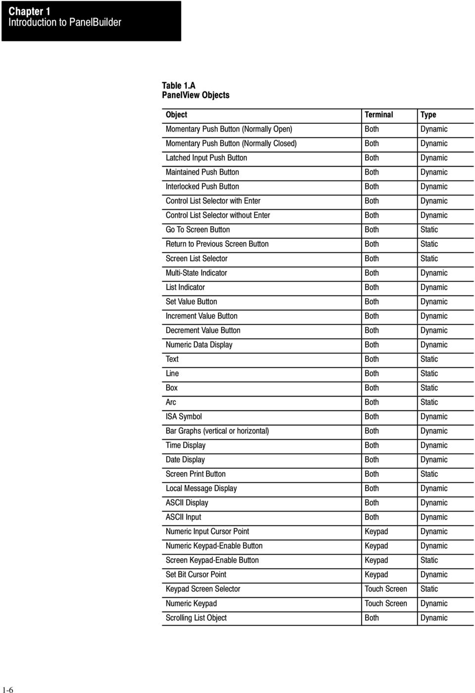
21 The following objects can be displayed on both the Keypad terminal and the Touch Screen terminal: Momentary Push Button (Normally Open) turns on (sets to 1) a PLC input control bit, as long as the button is held. Momentary Push Button (Normally Closed) resets a PLC input control bit that is normally set to 1. This bit stays off as long as the button is pressed. Latched Input Push Button turns on a PLC input control bit and holds the bit on until the PanelView terminal sees a PLC output bit (handshake bit) turn on. Maintained Push Button turns on a specific PLC input control bit until the button is pressed a second time. Interlocked Push Buttons are several push buttons which function as a group. When you press one of the buttons, it cancels the other buttons and makes the selection. The PLC controller is informed via a common PLC input address which button in the group is the currently selected option. Control List Selector with Enter contains a vertical list of operator choices. An operator can use the object s Up Cursor and Down Cursor buttons to move an arrow through the available selections. The selection is only sent to the PLC controller when the Enter button is pressed. Control List Selector without Enter contains a vertical list of choices. The operator uses the object s Up Cursor and Down Cursor buttons to move through the available selections. The current selection is automatically sent to the PLC controller via the object s PLC input control address. Go To Screen Button allows the operator to switch to an assigned screen. Return to Previous Screen Button switches back to the previous screen. Screen List Selector allows an operator to choose a screen from a list. Multi-State Indicator is a display area with up to sixteen different display states, each with a unique combination of text, colors and attributes. The value in the PLC address determines which state is displayed. 1-7
22 List Indicator displays a list of PLC states and highlights the current state. The value of the PLC address determines the item that will be highlighted in the list. Set Value Button transfers a pre-defined value to the PLC controller via the assigned PLC input address. Increment Value Button increases the PLC input value each time the button is pushed. If the button is held down the PLC input value continues to increase to a pre-assigned upper limit. Decrement Value Button decreases the value stored at a PLC input address each time the button is pushed. If the button is held down the PLC value continues to decrease to a pre-assigned bottom limit. Numeric Data Display displays the current value of an assigned PLC address (binary, BCD, or integer). Scaling (Y=Mx+b) and other options can be used to display the number in appropriate units. Text is used for screen titles, to provide instructions, or for any text that is not bound to an object. Lines (Horizontal, vertical and diagonal) are used to illustrate, and to separate sections of screens. Boxes are graphic objects like lines, which can surround other objects or simply illustrate. Arcs are used to illustrate quarter, semi, and three quarter circles, as well as circles. They can also be used to connect line objects to form rounded corners. ISA Symbols (32 in total) allow you to assign display attributes to four possible states for each symbol object. The symbols have two sizes: large and small. See Appendix D, ISA Symbols, for symbol illustrations. Bar Graphs can be used to monitor changing conditions, such as temperature or fluid levels. Each graph can be up to 80 characters wide and 24 characters high. Time Display can be located anywhere on the screen. Date Display can be located anywhere on the screen. Screen Print Button allows an operator to print any screen currently displayed on the PanelView terminal. 1-8
23 Local Message Display can be defined as a rectangular area of any size, and placed in any location on the PanelView screen. A PLC control address is assigned to the object, allowing the PLC controller to trigger any one of up to 875 local messages to appear in this area. ASCII Display is used to display a character string, sent from the PLC controller, directly on the PanelView terminal. The display is updated whenever the string changes. ASCII Input objects are on-screen keyboards which allow you to create a text string and send it to the PLC controller. Scrolling List object is an extended and enhanced control list selector/list indicator that is not limited by the number of lines on the screen. The Scrolling List object can consist of any combination of local message display, multi-state indicator, and numeric display lists, with up to 999 items in each list. The Scrolling List object reduces PLC ladder logic and addressing typically needed to display and edit large amounts of data. The Scrolling List object can be used to control and monitor sequential operations in both auto and manual modes or to provide operators with a selection list. The following objects can be displayed only on a Keypad terminal: Numeric Input Cursor Point consists of a numeric display and a cursor character. This object can be used to enter numbers into an array of numeric fields similar to an array of thumb-wheel switches on a control panel. This object has an associated PLC input address in which the value is communicated to the PLC controller. Numeric Keypad-Enable Button pops up the Numeric Entry Scratchpad in which the operator can enter a number. The number is then stored in the specified PLC input address. Screen Keypad-Enable Button pops up the Numeric Entry Scratchpad in which the operator can enter a screen number. The screen with that number is displayed. Set Bit Cursor Point consists of a bit and a cursor character. This object is used to point to a screen character. Several set bit cursor points can be in the same screen. Each one can have a different (user defined) pointer; only the current pointer is visible and blinking. The current cursor point s input bit is always on, so the PLC controller always knows the current selection. 1-9
24 Both the set bit and numeric input cursor points can be used on the same screen. The following objects can be displayed only on a Touch Screen terminal: Numeric Keypad is used to send a value to the PLC controller. A unique PLC input address is assigned to each Numeric Keypad; the value that the operator enters is stored at this address. The keypad is available in large and small sizes. Keypad Screen Selector allows an operator to display a screen by entering the screen number. The selector is available in large and small sizes. The Information and Alarm Windows can pop up on the screen at any time to display important information: Information Window displays a message when triggered by the PLC controller. The window remains until the operator presses the Clear/ACK button, or until the PLC controller clears it. There can be as many as 496 different messages for the Information Window. Alarm Window is similar to the Information Window but with many additional features. Each message can be configured to sound the audio indicator (beeper), trip the alarm relay or print a message on a printer. Alarms are time and date stamped and listed in the order they occur. The operator can acknowledge the alarm, clear the display, silence the alarm, view the Alarm History Screen, or view the Alarm Status Screen. There can be as many as 496 different messages for the Alarm Window. The following options can be controlled by the PLC controller: PLC Controlled Audio allows the PLC controller to control the PanelView terminal s audio beeper. A PLC bit address is assigned; when the PLC controller sets this bit, the terminal s beeper is activated. This does not interfere with the Alarm Window s use of the beeper. PLC Controlled Alarm Relay allows the PLC controller to control the PanelView terminal s alarm relay. A PLC bit address is assigned, and when the PLC controller sets this bit, the terminal s alarm relay is energized. This does not interfere with the Alarm Window s use of the relay. 1-10
25 PLC Controlled Alarm Quantity/Accum Time Reset allows the PLC controller to reset the alarm count and the accumulated time in-alarm total. These totals are shown in the Alarm Status screen. PLC Controlled Screen Number allows the PLC controller to control which screen is displayed. When the PLC controller puts a screen number in an assigned address, PanelView displays the screen. This PLC controlled screen change always has precedence over operator-controlled screen changes, and operator-generated screen changes are only allowed if the PLC address contains 0. PLC Controlled Screen Print allows the PLC controller to trigger a printout of the screen displayed on the PanelView terminal. PLC Controlled Time and Date allows the PanelView terminal to read the time and date from the PLC controller and set its internal clock. PLC Controlled Clear Window clears the alarm window, the alarm beeper and the alarm relay when a 0 to 1 transition is detected in the assigned PLC address bit. PLC Controlled Silence Alarms silences the beeper and deactivates the alarm relay when a 0 to 1 transition is detected on this bit. PanelView terminals can be connected to any Allen-Bradley 1771 Remote I/O Link. Applicable host controllers include almost all Allen-Bradley Programmable Logic Controllers as well as certain IBM computers, VME Controllers, and the DEC Q-Bus interface. Newly released Allen-Bradley programmable controllers that are not yet listed will support PanelView terminals, as long as they support the 1771 remote I/O link. The PanelView terminal appears as one or more I/O rack(s) to a programmable controller. It has the same configurability and more as a standard I/O rack. Refer to your applicable Allen-Bradley Programmable Controller and Remote I/O Scanner user s manuals for various connection and remote I/O configuration limitations. Chapter 4, Planning Your Application, describes how to determine rack numbers, sizes, etc. 1-11
26 You can connect one or more PanelView terminals directly to a PLC-5 Remote I/O Port (in Scanner Mode) along with other I/O racks. If the PLC-5 Remote I/O Port is used in the adapter mode, one or more PanelView terminals can be connected to that PLC-5 along with other I/O racks via a 1771-SN I/O Subscanner Module. All Series C Rev A and later terminals can communicate at 230.4K baud with any PLC-5 capable of supporting that baud rate. If you are using a PLC-5/15 with partial rack addressing and block transfers, you must use PLC-5/15 series B, revision J or later. One or more PanelView terminals can be connected to this processor along with other I/O racks via the 1771-SN I/O Subscanner Module. One or more PanelView terminals can be connected directly to a PLC-3 or PLC-3/10 remote I/O Scanner along with other I/O racks. If you are using a 1775-S4A Remote Scanner /Distribution panel, you must use Series B or higher. 1-12
27 This includes the PLC-2/05, 2/15, 2/30, 2/40, etc. One or more PanelView terminals can be connected to these processors along with other I/O racks via the 1771-SN I/O Subscanner Module. If you are using a 1772-SD2 Scanner /Distribution panel, you must use revision 3 or later. One or more PanelViews can be connected to the 1747-SN I/O Subscanner Module (SLC 500 RIO connection) for the SLC 5/02 processor. Each module provides an additional remote I/O link for the host programmable controller. The rack range of the 1747-SN is 0 to 3. IMPORTANT: With the SLC 5/02 and 1747-SN module, no block transfers are possible. One or more 1771-SN I/O Subscanner Modules can be installed in any standard Allen-Bradley 1771 I/O rack. Each module provides an additional remote I/O link for the host programmable controller. One or more PanelView terminals can be connected to any of the previously mentioned processors along with other I/O racks via a 1771-SN I/O Subscanner Module. Refer to the 1771-SN Sub I/O Scanner Module Data Sheet for specific details. This module can be installed in an IBM PC or compatible computer to provide the computer with an Allen-Bradley 1771 Remote I/O Link. You can then connect Allen-Bradley Remote I/O racks and devices such as the PanelView terminal to this computer. This module can be installed in a VME backplane, providing the VME controller with an Allen-Bradley 1771 Remote I/O Link. Allen-Bradley Remote I/O racks and devices such as the PanelView terminal can then be connected to this VME controller. 1-13
28 This module can be installed into a DEC Q-Bus controller to provide it with an Allen-Bradley 1771 Remote I/O Link. Allen-Bradley Remote I/O racks and devices such as the PanelView terminal can then be connected to this controller. 1-14
29 This chapter includes information on: PanelBuilder s hardware and software requirements how to install and start up PanelBuilder the compatibility of older versions of PanelView terminals with applications created by the current release of PanelBuilder PanelBuilder requires DOS 3.0 or above. PanelBuilder Development Software requires one of the following computers: Allen-Bradley 1784 series industrial terminals and laptop computers Allen-Bradley 6120 series industrial computers and 6160 series industrial workstations IBM XT, AT, PS/2 or 100% compatible In addition your system must have: one of the following video adapters and appropriate monitors: Standard Monochrome Adapter Hercules Graphics Card Color Graphics Adapter (CGA ) Enhanced Graphics Adapter (EGA ) Video Graphics Array (VGA ) Screens for all terminals can be created using either a monochrome or color monitor. at least 640K of RAM a floppy drive capable of reading the disks 2-1
30 a hard disk with at least 1.55Mb free space an RS-232 Serial Port: this port is required to upload and download application files to and from your PanelView terminal an Upload/Download cable: this cable connects the development computer s RS-232 port to the PanelView terminal s RS-232 port The original PanelBuilder Development Software disks are not for running the software. The floppy disks contain data-compacted, non-executable files. The INSTALL procedure converts these files into executable form so that PanelBuilder can run. The files can then be copied using standard DOS commands. Some of these files are for demonstration use and can be erased. Á Á Á Á Á Á Á Á Á Á Á Á Á 2-2
31 Á ÁÁ Á Á Á Á Á Á Á Á Á Á Á Á ÁÁ The Remote I/O Pass-Through Utility disk is now provided with the PanelBuilder Development Software disk set. You must install the Remote I/O Pass-Through Utility to upload and download application files via the Data Highway + and Remote I/O networks. To install the Remote I/O Pass-Through Utility, place the disk labeled Remote I/O Pass-Through Utility in a floppy drive, and at the DOS prompt, type: install press Enter For information on uploading and downloading via pass-through, refer to Chapter 6, File Operations, in the PanelBuilder Development Software User Manual. A DEFAULTS file is created when you first run PanelBuilder. The file contains the default parameters for the mouse; the ports; the data file directory; the display colors for PanelBuilder menus; and for all touch screen and function key objects. 2-3
32 If your system contains a default file from an earlier version of PanelBuilder, the file will be converted to version 5 format, and your previously configured defaults will apply to the new installation. A copy of the original file will be renamed as DEFAULT.nnn, where nnn is the previous version number. (A defaults file from version 2.0 of PanelBuilder, for example, would be renamed and saved as DEFAULTS.200.) PanelBuilder Development Software is distributed on floppy disks. Before installing PanelBuilder, make a backup copy of the original software. Store the original software in a safe place and install PanelBuilder from the copy. The software installation program creates a disk directory for PanelBuilder and copies all the necessary files. By default, the directory is \PDS on drive C. Insert the (first) PanelBuilder Development Software disk in drive A and switch to drive A. Type: A: press Enter To run the installation program, type: install press Enter Follow the instructions on the screen. If you wish to install the software in some other directory or drive, you can change the drive and the pathname when prompted by the installation program. Follow these steps to start PanelBuilder: 1. Turn on the computer; if you are prompted, enter the time and date. 2. If the directory path isn t specified, change to the PDS directory. If you followed the INSTALL example, PanelBuilder is on the C drive. Type: C: press Enter CD PDS press Enter 2-4
33 3. To start the program type: PDS press Enter PanelBuilder Development Software has been upgraded four times: in version 2, version 3, version 4 and now version 5. As long as only the original objects and original features are used, your application file will run on all PanelView terminals. If version 2 objects are used in your application, the application will run on version 2, 3, 4 and 5 terminals, but not on version 1 terminals. If version 3 objects are used in your application, it will run only on version 3, 4 and 5 terminals. Version 4 objects run on version 4 and 5 terminals. Enabling any of the new objects in version 5 will make your application compatible with version 5 terminals only. For a new application, the Version 5.0 PanelBuilder menus will default to Version 5.0 features. See Figure 2.1 for modifying PanelBuilder menus. 2-5
34 23020 When you re developing an application file, PanelBuilder displays the lowest level of compatibility for the application, at the left of the status line
35 Whenever you add or edit an object or enable or disable a feature in a way that affects the file s compatibility with various terminals, a message will appear to inform you of the change. In the unlikely event that version 1 firmware EPROMs are re-installed after a terminal has been run with version 2, 3, 4 or 5 firmware EPROMs, the following default settings will be lost: serial port settings access codes audio response alarm relay preset operations screen saver stuck button timeout screen alignment pass-through configuration The firmware version is displayed on the PanelView terminal Configuration Mode Menu screen along with the date of release, internal version number and the current time and date. 2-7
36 23593 In Figure 2.3 the Firmware Rev indicates version 5. Version 1 firmware is shown as 01.xx.xx., version 2 as 02.xx.xx, version 3 as 03.xx.xx and version 4 as 04.xx.xx. PanelBuilder can print a report listing all objects and global functions in an application file. The report lists all screens and all objects used in a file. More important for those with older terminals, the object listing shows the version of firmware that is required for each object. With this report, you can identify which objects must be removed or modified to make an application file compatible with older terminals. For details on how to print reports, see Chapter 6, File Operations. 2-8
37 This chapter describes the basics of PanelBuilder including how to get help and how to use the menus and the keyboard. Press F1 to display a help screen relevant to the screen or object you re working on. Certain keys are used to move through menus, enter data, or work with objects on a screen. This section illustrates these keys and describes their functions within the PanelBuilder software. The menu keys help you move quickly through the menus and the options they provide. The Escape key closes an open menu. The Enter key chooses the highlighted option. The Up and Down arrow keys move upward and downward through the menu options. The Down arrow also opens a menu. The Left and Right arrow keys move horizontally through a selection of menus. These keys also close a menu and open the next one to the right or the left. The space bar moves horizontally through a selection of menus, or vertically through the options of a single menu. 3-1
38 The Home key moves to the first item in a menu or selection. The End key moves to the last item in a menu. The F1 key displays the Help Screen. The F2 key toggles the bottom status line on and off. A Shortcut In most menus, typing the first letter of an option s name highlights that option and opens that option s window. Data is entered by choosing an item from a list or by typing in the required information. Use the following keys when entering data. The Escape key cancels the entry without saving the information. The Enter key saves information once it is entered or chosen. The Up and Down arrows move through a list of choices. The Left and Right arrows move the cursor through typed information, for editing. Pg Up moves several items upwards in a list or menu. 3-2
39 Pg Dn moves several items downwards in a list or menu. Home moves the cursor to the top of a list or to the beginning of a data entry field. End moves the cursor to the bottom of a list, or to the end of a data entry field. Ctrl-End clears from the cursor to the end of a data entry field. Ctrl-Home clears a data entry field. Insert toggles between insert and over-strike modes in a data entry field. The following keys are used to edit objects or lines on the screen. Escape cancels the current operation and returns to the menu. Enter finishes and saves the current operation and returns to the menu. Tab or Shift Right moves the cursor, or the object, eight columns to the right. 3-3
40 Shift Tab or Shift Left moves the object, or cursor, eight columns to the left. Shift Up moves the object, or cursor, two rows up. Shift Down moves the object, or cursor, two rows down. Shift Home moves the object or cursor diagonally two rows up and eight columns to the left. Shift End moves the object or cursor diagonally two rows down and eight columns to the left. Shift Pg Up moves the object or cursor diagonally two rows up and eight columns to the right. Shift Pg Dn moves the object or cursor two rows down and eight columns to the right. The Right arrow key moves the cursor, or the object, to the right. It also draws or erases a horizontal line segment to the right. If you are setting the size of an object, the Right arrow makes it larger. The Left arrow key moves the cursor, or the object, to the left. It also draws and erases a horizontal line segment to the left. If you are setting the size of an object, the Left arrow makes it smaller. The Up arrow moves the cursor or object upwards. It also draws or erases a vertical line segment upwards. If you are setting the size of an object, pressing the Up arrow makes it smaller. The Down arrow moves the cursor, or the object, downwards. It also draws or erases a vertical line segment downwards. If you are setting the size of an object, pressing the Down arrow makes it larger. 3-4
41 Pg Up moves the cursor or object diagonally up and to the right. If you are sizing an object, this key will increase the width and decrease the height of the object. Pg Up also draws or erases a diagonal line segment up and to the right. Pg Down moves the object, or cursor, diagonally down and to the right. If you are sizing an object, this key increases the width and height of the object. Pg Down also draws or erases a diagonal line segment down and to the right. Home moves the object or cursor diagonally up and to the left. If you are sizing an object, this key decreases the width and height of the object. The Home key also draws and erases a diagonal line segment up and to the left. End moves the object or cursor diagonally down and to the left. If you are sizing an object, the End key decreases the object s width and increases its height. The End key also draws and erases a diagonal line segment down and to the left. Ctrl Right moves the cursor to the next text string when editing display text. Ctrl Left moves the cursor to the previous text string when editing display text. Press the Ctrl or the Alt key to use the alternate character set for typing object text. The set is illustrated in Appendix E, The Extended Character Set. The F3 key identifies the object being edited by causing it to blink. 3-5
42 Figure 3.1 provides a guide for the menu structure of PanelBuilder Development Software. Note that the Object Menu, at the bottom, shows 16 different items; in actual use, you will never see all of the items at once. The contents of the Object menu change depending on the object being edited The Main menu is the first menu displayed when PanelBuilder starts up, and the last one displayed before shut-down. It contains the menus that allow you to create, edit and manipulate application files. The Main menu also allows you to send or receive application files to or from the PanelView terminal, print reports on application screens, and set the software for the creation of screens. 3-6
43 To open the Main menu, press any key when the Introduction Screen is displayed To open the Develop menu, highlight Develop and press Enter. Use this menu to create new application files, or to edit existing ones Select File displays a list of application files which can be loaded and edited. 3-7
44 Create New File allows you to make a new application file. After you choose this option, type in a name for the new file and press Enter. You ll be asked if the file is for a Touch Screen or Keypad terminal. Choose one or the other, and a new application file will be created. Directory shows the current directory setting. Type in a different disk or directory name to change the directory for loading or saving application files. Choose Transfer from the Main menu, to open the Transfer menu. Use this menu to send and receive application files to and from the PanelView terminal Download to PanelView Terminal (RS-232) sends a finished application file to a terminal. The process involves the following steps: 1. Choose the file you want to send. 2. Establish the communications port. 3. Send the file. Upload from PanelView Terminal (RS-232) retrieves an application file from a PanelView terminal for editing. Pass-Through Download to PanelView (DH+ and Remote I/O) allows you to download PanelView files via a PLC-5 on a Data Highway+ and remote I/O network. Before trying a pass-through download or upload, refer to Chapter 6, File Operations. 3-8
45 Pass-Through Upload from PanelView (DH+ and Remote I/O) allows you to upload PanelView files via a PLC-5 on a Data Highway+ and Remote I/O network. For more information on pass-through download or upload, refer to Chapter 6, File Operations. Burn EPROMs allows an application file to be copied into EPROMs for installation onto a PanelView terminal. Before burning EPROMs, refer to Chapter 6, File Operations. Burn Single EPROM allows an application file to be burned into a single EPROM for use with Series D or E terminals. This option must also be used for upgraded older terminals with logic boards accepting only one EPROM. Choose Reports from the Main menu and the Reports menu appears. Use this menu to generate printed reports of application files you have created. For more information on reports and how to print them, see Chapter 6, File Operations Select File presents a list of application files. Choosing any one will open other menus where you can choose the types of reports you wish to print, and choose a printer port. Directory changes the directory setting, allowing you to locate files for printing. Choose Files from the Main menu to open the Files menu. Use this menu to copy, erase, rename, and move files to different disk directories. 3-9
46 20014 Application Files opens a menu that allows you to copy, erase and rename application files. Hex Files opens a menu that allows you to copy, delete and rename hex files. (Hex files are application files in Intel hex format the format for burning into EPROMs). All Files provides the same options for DOS files as those provided in Application and Hex Files. Choose Setup from the Main menu to open the Setup menu. Use this menu to set various attributes for the PanelBuilder software, including the color of PanelBuilder s menus and text, and the time and date Colors permits you to choose the default palette of colors, or select your own colors for the menus, data fields, etc., that will appear in PanelBuilder during screen development. 3-10
47 Mouse allows you to use a mouse in PanelBuilder. A variety of serial and bus mouse packages are available commercially, including software drivers that emulate the functions of the arrow keys and Enter. To use a mouse, you must install the driver and configure it to output the cursor key codes when the mouse is moved. Similarly, the codes for the Enter key and the Esc key must be assigned to two of the mouse s buttons. Refer to the mouse s documentation for details. Choosing Mouse allows you to adjust the damping factors the amount of mouse movement required to move the screen cursor. Keep in mind the following points: a lower number moves the cursor further with the same mouse movement with a bus mouse the damping factors may have to be set much higher than the default settings settings that are too high or too low may cause undesirable operation IMPORTANT: Allen-Bradley does not provide mouse driver software for PanelBuilder. Ensure that the mouse package you purchase includes driver software that allows the mouse to emulate the arrow, Enter, and Esc keys. To use the cursor keys on the keyboard, the mouse option must be disabled. For information on how to interface the following mouse packages, ask your Allen-Bradley representative for a copy of the application note Using a Mouse with PanelBuilder Development Software: Microsoft Serial Mouse Version 7.03 Microsoft Bus Mouse Logitech Serial Mouse Version 4.01 Mouse Systems Serial White Mouse or Mouse Systems PC Mouse II Version 6.23 Time & Date allows you to change the system s time and date clock. Information provides information on the version number of the PanelBuilder software. For more details on version control, see Chapter 2, Installing PanelBuilder. 3-11
48 Choose Exit from the Main menu to leave PanelBuilder The File menu consists of five menus which allow you to edit application files. To open the File menu, choose Select File or Create New File from Develop in the Main menu
49 Choose Screens from the File menu and the Screens menu appears, where you create or edit screens and assign security levels Select Screen chooses a screen from the application file. Create New Screen makes a new screen to work on. Utilities allows you to copy, delete or rename screens, and assign screen security levels. For details on the Utilities menu see Chapter 8, Screen Operations. Powerup Screen allows you to specify the screen to be displayed when the PanelView terminal starts up. Application File Comment allows you to add a 24 character message about the application file. Once you have returned to the Files menu, choose Windows to open the Windows menu. Use this menu to: configure the Alarm and Information windows set the colors for the Terminal Fault, Alarm History and Alarm Status screens set the numbers for the Alarm History and Alarm Status screens view alarm and information messages 3-13
50 For more information see Chapter 7, Information and Alarm Windows Alarm Window allows you to configure an alarm window for the application file being edited. You can specify the alarm and information messages and configure them to sound the alarm, trigger the alarm relay, or print an alarm. You can also specify color (for a color terminal) and size of the window, assign the PLC control address, define how alarm acknowledgement will be communicated to the PLC controller, and choose from various PLC controlled options. Information Window allows you to configure an information window for the application file being edited. You can specify the information messages, the color (for a color terminal) and size of the information window, assign the PLC control address, and enable an acknowledge indicator that tells the PLC controller when a message has been acknowledged. Terminal Fault Window permits you to set the colors for the Fault Window on a color PanelView terminal. Alarm History Screen permits you to set the screen number for the alarm history screen, and for a color terminal, set the screen colors. Alarm Status Screen permits you to set the screen number for the alarm status screen. It also allows you to enable/disable the Alarm Status Reset Button, set the PLC Controlled Qty/Time Reset address, and set the Qty/Time Reset to PLC Controller. Finally, in this screen you can set the screen colors for a color terminal. Numeric and Security Entry Window allows you to set the Numeric Entry and Security Window colors on a color system. 3-14
51 Choose Options from the File menu to open the Options menu. Use this menu to: specify the PanelView display type including button delay, repeat options and various PLC controlled functions use the optional user EEPROM as a source of extra application memory, to expand the application memory to 128K set status/control bits which are used during pass-through transfer on a Data Highway Display Menus for Terminal Version allows you to set PanelBuilder s menus so the files you create will be compatible with version 1, version 2, version 3, version 4 or version 5 of PanelView terminal firmware. Only available features and objects compatible with the version you select will be displayed. For more information on version control see Chapter 2, Installing PanelBuilder. PanelView Display Type sets the type of monitor that the application will run on either monochrome or color. For a color display, you can set and change the palette of colors. You can create an application for a color terminal even if your development system has a monochrome monitor. 3-15
52 User Memory Limit allows you to set the maximum amount of application memory the file can occupy. With the standard amount of application memory in the terminal (64K) you can choose whether or not to retain the Alarm Status Screen data (the alarm count and accumulated time in-alarm) in battery-backed memory. By choosing not to retain this data in battery-backed memory, you increase the amount of memory available to applications you have developed. To extend the amount of memory even further, use the optional user EEPROM for extra application memory. Then you can choose one of the 128K memory options. IMPORTANT: A User EEPROM must be installed in the terminal to supply the extra memory. When the EEPROM is used for extended application memory, it can t be used to back up the application file The default is 62,976 Alarm Status Screen NOT Data Battery-Backed. The setting you choose is saved in the application file. IMPORTANT: Your application file size must be in the same range as the terminal s memory configuration. If your file will fit into the lower memory setting (59,904 or 62,976), choose one of these options. If you select either of the higher options (124,928 or 128,000), the following message will be displayed: 3-16
PanelView Standard Operator Terminals
 PanelView Standard Operator Terminals User Manual (Catalog Numbers PV300 Micro, PV300, PV550, PV600, PV900, PV1000, PV1400) Important User Information Solid state equipment has operational characteristics
Allen-Bradley. User Manual. PanelView 1200/1400e Transfer Utility. (Cat. No. 2711E ND7)
") Allen-Bradley PanelView 1200/1400e Transfer Utility User Manual (Cat. No. 2711E ND7) Important User Information Because of the variety of uses for the products described in this publication, those responsible
Allen-Bradley PanelView 1200/1400e Transfer Utility User Manual (Cat. No. 2711E ND7) Important User Information Because of the variety of uses for the products described in this publication, those responsible
PanelView e Transfer Utility
 PanelView e Transfer Utility (Cat. No. 2711E-ND7) User Manual Important User Information Because of the variety of uses for the products described in this publication, those responsible for the application
Model 288B Charge Plate Graphing Software Operators Guide
 Monroe Electronics, Inc. Model 288B Charge Plate Graphing Software Operators Guide P/N 0340175 288BGraph (80207) Software V2.01 100 Housel Ave PO Box 535 Lyndonville NY 14098 1-800-821-6001 585-765-2254
Allen-Bradley. User Manual. PanelView e Transfer Utility. (Cat. No. 2711E ND7)
") Allen-Bradley PanelView e Transfer Utility User Manual (Cat. No. 2711E ND7) Important User Information Because of the variety of uses for the products described in this publication, those responsible for
Allen-Bradley PanelView e Transfer Utility User Manual (Cat. No. 2711E ND7) Important User Information Because of the variety of uses for the products described in this publication, those responsible for
WinPFT File Transfer Utility (Catalog No. 2711-ND7)
") Technical Data WinPFT File Transfer Utility (Catalog No. 2711-ND7) Overview WINPFT is a stand-alone Windows utility which lets you transfer applications developed for standard PanelView terminals or Dataliner
Technical Data WinPFT File Transfer Utility (Catalog No. 2711-ND7) Overview WINPFT is a stand-alone Windows utility which lets you transfer applications developed for standard PanelView terminals or Dataliner
Legal Notes. Regarding Trademarks. 2012 KYOCERA Document Solutions Inc.
 Legal Notes Unauthorized reproduction of all or part of this guide is prohibited. The information in this guide is subject to change without notice. We cannot be held liable for any problems arising from
User Manual. DG LINK Application Program 071-0056-50. www.tektronix.com. This document applies to firmware version 2.00 and above.
 User Manual DG LINK Application Program 071-0056-50 This document applies to firmware version 2.00 and above. www.tektronix.com Copyright Tektronix Japan, Ltd. All rights reserved. Copyright Tektronix,
SLC 5/05 Processors Firmware/Operating System ControlFLASH Upgrade
 Installation Instructions SLC 5/05 Processors Firmware/Operating System ControlFLASH Upgrade Catalog Numbers 1747-DU501 Topic Page System Requirements 3 Install ControlFLASH 3 Prior to Running ControlFLASH
Getting Started on the Computer With Mouseaerobics! Windows XP
 This handout was modified from materials supplied by the Bill and Melinda Gates Foundation through a grant to the Manchester City Library. Getting Started on the Computer With Mouseaerobics! Windows XP
Windows XP Pro: Basics 1
 NORTHWEST MISSOURI STATE UNIVERSITY ONLINE USER S GUIDE 2004 Windows XP Pro: Basics 1 Getting on the Northwest Network Getting on the Northwest network is easy with a university-provided PC, which has
Embroidery Fonts Plus ( EFP ) Tutorial Guide Version 1.0505
 Tutorial Guide Version 1.0505") Embroidery Fonts Plus ( EFP ) Tutorial Guide Version 1.0505 1 Contents Chapter 1 System Requirements.................. 3 Chapter 2 Quick Start Installation.................. 4 System Requirements................
Embroidery Fonts Plus ( EFP ) Tutorial Guide Version 1.0505 1 Contents Chapter 1 System Requirements.................. 3 Chapter 2 Quick Start Installation.................. 4 System Requirements................
NETWORK PRINT MONITOR User Guide
 NETWORK PRINT MONITOR User Guide Legal Notes Unauthorized reproduction of all or part of this guide is prohibited. The information in this guide is subject to change without notice. We cannot be held liable
Newton Backup Utility User s Guide. for the Windows Operating System
 Newton Backup Utility User s Guide for the Windows Operating System K Apple Computer, Inc. 1995 Apple Computer, Inc. All rights reserved. Under the copyright laws, this manual may not be copied, in whole
Universal Serial Bus (USB) to DH-485 Interface Converter
 to DH-485 Interface Converter") Installation Instructions Universal Serial Bus (USB) to DH-485 Interface Converter Catalog Number 1747-UIC Contents Overview..................................................3 Computer and Operating System
Installation Instructions Universal Serial Bus (USB) to DH-485 Interface Converter Catalog Number 1747-UIC Contents Overview..................................................3 Computer and Operating System
M&M Refrigeration, Inc. PC Monitor. User s Manual
 M&M Refrigeration, Inc. PC Monitor User s Manual PC Monitor Copyright protection claimed includes all forms and matters now and hereinafter granted protection by statutory or judicial law, including unlimited
User Manual. DeviceNet Network Configuration
 User Manual DeviceNet Network Configuration Important User Information Solid-state equipment has operational characteristics differing from those of electromechanical equipment. Safety Guidelines for the
Productivity Software Features
 O P E R A T I O N S A N D P R O C E D U R E S F O R T H E P R O D U C T I V I T Y S O F T W A R E Productivity Software Features Remote CS-230 calibration and set-up on a personal computer. CS-230 calibration
POS-X Stock Manager User s Guide
 POS-X Stock Manager User s Guide Version 1.3 Copyright 2005 POS-X Inc. All rights reserved. POS-X.com 1-800-790-8657 1 POS-X Stock Manager User s Guide Stock Manager Version 1.1.67 POS-X Inc. Telephone:
File Management Utility. T u t o r i a l
 File Management Utility T u t o r i a l Contents System Requirements... 2 Preparing Files for Transfer to GlobalMark... 2 Application Launch... 2 Printer Setup... 2 Communication Status... 4 Communication
Instruction manual. testo easyheat Configuration and Analysis software
 Instruction manual testo easyheat Configuration and Analysis software en 2 General Information General Information This documentation includes important information about the features and application of
ERC-to-MRC JOB TRANSLATOR MANUAL
 Yasnac MRC Controller ERC-to-MRC JOB TRANSLATOR MANUAL Part Number 133110-1 Yasnac MRC Controller ERC-to-MRC Job Translator Manual Part Number 133110-1 June 13, 1995 MOTOMAN 805 Liberty Lane West Carrollton,
IT Quick Reference Guides Using Windows 7
 IT Quick Reference Guides Using Windows 7 Windows Guides This sheet covers many of the basic commands for using the Windows 7 operating system. WELCOME TO WINDOWS 7 After you log into your machine, the
13-1. This chapter explains how to use different objects.
 13-1 13.Objects This chapter explains how to use different objects. 13.1. Bit Lamp... 13-3 13.2. Word Lamp... 13-5 13.3. Set Bit... 13-9 13.4. Set Word... 13-11 13.5. Function Key... 13-18 13.6. Toggle
OFFICE KEYBOARD (MT1210 & MT1405) OFFICE FEATURES
 OFFICE FEATURES") OFFICE KEYBOARD (MT1210 & MT1405) OFFICE FEATURES Thank you for purchasing OFFICE KEYBOARD. This User s manual contains all information that helps you to operate your keyboard. Please keep the software
OFFICE KEYBOARD (MT1210 & MT1405) OFFICE FEATURES Thank you for purchasing OFFICE KEYBOARD. This User s manual contains all information that helps you to operate your keyboard. Please keep the software
3NNet KVM CP-104S /OSD / 19 KVM CP-108S / OSD / 19 KVM CP-116S / OSD / 19
 3NNet USERS MANUAL KVM CP-104S /OSD / 19 KVM CP-108S / OSD / 19 KVM CP-116S / OSD / 19 RACK MOUNTABLE 4 / 8 / 16 PORT PS2 KVM SWITCH Rev 1.1 TABLE OF CONTENTS INTRODUCTION.. 3 FEATURES... 3 PACKAGE CONTENTS........
#65 4GHGTGPEG")WKFG #FXCPEGF"6GTOKPCN"5QHVYCTG 8GTUKQP"502 HQT"%QPVTQNNGT/#% Catalog # 100123 Rev.02
WKFG #FXCPEGF6GTOKPCN5QHVYCTG 8GTUKQP502 HQT%QPVTQNNGT/#% Catalog # 100123 Rev.02") #65 #FXCPEGF"6GTOKPCN"5QHVYCTG 8GTUKQP"502 HQT"%QPVTQNNGT/#% 4GHGTGPEG")WKFG Catalog # 100123 Rev.02 &RS\ULJKWý ý ýìääçñýìääåýe\ý(vkhgý5rerwhfýõìäåëôý/lplwhgï 2FWREHUýìääåýõ3')ýYHUVLRQô &DWDORJýúìííìëêý5HYïíë
#65 #FXCPEGF"6GTOKPCN"5QHVYCTG 8GTUKQP"502 HQT"%QPVTQNNGT/#% 4GHGTGPEG")WKFG Catalog # 100123 Rev.02 &RS\ULJKWý ý ýìääçñýìääåýe\ý(vkhgý5rerwhfýõìäåëôý/lplwhgï 2FWREHUýìääåýõ3')ýYHUVLRQô &DWDORJýúìííìëêý5HYïíë
Xerox DocuPrint P12 Print Driver User Guide
 Xerox DocuPrint P12 Print Driver User Guide Xerox Corporation 800 Phillips Road Webster, New York 14580 1998 Xerox Corporation. Xerox, The Document Company, the stylized X, and the identifying product
History of Revisions. Ordering Information
 No part of this document may be reproduced in any form or by any means without the express written consent of II Morrow Inc. II Morrow, Apollo, and Precedus are trademarks of II Morrow Inc. Windows is
RFID Logger Software User Manual Rev 1.0
 RFID Logger Software User Manual Rev 1.0 Table of Contents 1. System Overview... 2 2. Installation... 2 3. USB RFID Interface Box... 3 4. Operation... 4 4.1. Start Up... 4 4.2. Menu overview... 4 4.2.1.
BIGPOND ONLINE STORAGE USER GUIDE Issue 1.1.0-18 August 2005
 BIGPOND ONLINE STORAGE USER GUIDE Issue 1.1.0-18 August 2005 PLEASE NOTE: The contents of this publication, and any associated documentation provided to you, must not be disclosed to any third party without
Operating Systems. and Windows
 Operating Systems and Windows What is an Operating System? The most important program that runs on your computer. It manages all other programs on the machine. Every PC has to have one to run other applications
 Control Technology Corporation CTC Monitor User Guide Doc. No. MAN-1030A Copyright 2001 Control Technology Corporation All Rights Reserved Printed in USA The information in this document is subject to
A+ Guide to Managing and Maintaining Your PC, 7e. Chapter 1 Introducing Hardware
 A+ Guide to Managing and Maintaining Your PC, 7e Chapter 1 Introducing Hardware Objectives Learn that a computer requires both hardware and software to work Learn about the many different hardware components
Introduction to LogixPro - Lab
 Programmable Logic and Automation Controllers Industrial Control Systems I Introduction to LogixPro - Lab Purpose This is a self-paced lab that will introduce the student to the LogixPro PLC Simulator
PPM Users Manual Signature Software 01-12-00
 PPM Users Manual Signature Software 0-2-00 PPM User Manual /8/02 Software Versions: 0.0.27 Contents. Introduction 2 2. Parameters 3 2. Overload Limit...4 2.2 Relative Upper Limit...4 2.3 Relative Lower
Manual. Danfoss Central Station Communications Software Version 3
 Manual Danfoss Central Station Communications Software Version 3 RS.8A.Q1.02 1-2001 Contents Introduction 4 System Overview 4 Minimum and Recommended Hardware Requirements 4 Using the Keyboard to Select
S7 for Windows S7-300/400
 S7 for Windows S7-300/400 A Programming System for the Siemens S7 300 / 400 PLC s IBHsoftec has an efficient and straight-forward programming system for the Simatic S7-300 and ern controller concept can
Hydras 3 LT Quick Start
 Catalog Number 6234218 Hydras 3 LT Quick Start SOFTWARE MANUAL December 2005, Edition 2 Hach Company, 2005. All rights reserved. Printed in the U.S.A. Catalog Number 6234218 Hydras 3 LT SOFTWARE MANUAL
Weather Capture Software Guide Version 1.4 Revision: June 10 2008
 Weather Capture Software Guide Version 1.4 Revision: June 10 2008 1 Introduction 2 Menu screen structure and navigation Menu Bar i. File ii. Display iii. Settings Alarm User Download Language iv. Help
AXIS Camera Station Quick Installation Guide
 AXIS Camera Station Quick Installation Guide Copyright Axis Communications AB April 2005 Rev. 3.5 Part Number 23997 1 Table of Contents Regulatory Information.................................. 3 AXIS Camera
Event Record Monitoring and Analysis Software. Software Rev. 3.0 and Up. User s Guide
 Event Record Monitoring and Analysis Software Software Rev. 3.0 and Up User s Guide 2 Contents Contents Chapter 1: About ERMAWin 4 Chapter 2: Overview 5 About this Manual 5 System Requirements 5 Installing
OVERVIEW Playbacks: Shortcuts: Memories: Data Entry Wheels: Touchpad: Master and Blackout:
 OVERVIEW The MIDIcon is a USB MIDI control panel designed to work alongside the Elation lighting software packages. The Midicon is USB powered and uses the USB class drivers so that no driver needs to
Upgrade Instructions. View Manager 96 v. 5.1. Software Upgrade
 WORLD LEADER IN ELECTRONIC SECURITY Upgrade Instructions View Manager 96 v. 5.1 1 Software Upgrade This software permits you to upgrade your VM96 version 3.x or 4.x system to the latest version of VM96
DIGICLIENT 8.0 Remote Agent Software
 DIGICLIENT 8.0 Remote Agent Software MODEL: D17800 Series Instruction Manual English Version 1.0 Copyright 2007 Digimerge Technologies Inc Table of Contents Table of Contents About the DigiClient 8.0...
2011, The McGraw-Hill Companies, Inc. Chapter 5
 Chapter 5 5.1 Processor Memory Organization The memory structure for a PLC processor consists of several areas, some of these having specific roles. With rack-based memory structures addresses are derived
Software User's Guide
 BROTHER QL-500/550/650TD/1050/1050N Software User's Guide QL-500 QL-650TD QL-550 QL-1050/1050N 1 Contents Contents....................................................................................2................................................................................4
User s Guide for version 5 Page
 Network Management Interface Catalog VPi 32.15E For use with these ATS products: 7000 & 4000 Series (Group 5 Controller) Series 300 (Group 1 Controller), and 940, 962, 436, 434, 447, 448 (Group 6A/7A Control
Intro to Excel spreadsheets
 Intro to Excel spreadsheets What are the objectives of this document? The objectives of document are: 1. Familiarize you with what a spreadsheet is, how it works, and what its capabilities are; 2. Using
PARTNER ACS R4.0 Remote Administration R4.0. Getting Started
 PARTNER ACS R.0 Remote Administration R.0 Getting Started 8-6-66 700080 Issue May 00 Copyright 00, Avaya Inc. Document 8-6-66 All Rights Reserved 700080 Printed in USA Issue May 00 Notice Every effort
Programming Logic controllers
 Programming Logic controllers Programmable Logic Controller (PLC) is a microprocessor based system that uses programmable memory to store instructions and implement functions such as logic, sequencing,
ZOOM/Share. Mouse Controlled Screen Magnifier. For MGA, CGA, EGA, VGA & Hercules Cards
 ZOOM/Share Mouse Controlled Screen Magnifier For MGA, CGA, EGA, VGA & Hercules Cards COPYRIGHT NOTICE This software is copyright (c) 1990-1991 by ORION Microsystems which reserves for itself all rights.
VisionMate Flat Bed Scanner 2D Tube Barcode Reader
 VisionMate Flat Bed Scanner 2D Tube Barcode Reader User s Manual Page 1 Catalog #3111 MAN-21256 Rev G Contact Information North America: Tel: 800.345.0206 email: matrix.info@thermofisher.com Europe: Tel:
QUICK START GUIDE. SG2 Client - Programming Software SG2 Series Programmable Logic Relay
 QUICK START GUIDE SG2 Client - Programming Software SG2 Series Programmable Logic Relay SG2 Client Programming Software T he SG2 Client software is the program editor for the SG2 Series Programmable Logic
WA Manager Alarming System Management Software Windows 98, NT, XP, 2000 User Guide
 WA Manager Alarming System Management Software Windows 98, NT, XP, 2000 User Guide Version 2.1, 4/2010 Disclaimer While every effort has been made to ensure that the information in this guide is accurate
Introduction To Microsoft Office PowerPoint 2007. Bob Booth July 2008 AP-PPT5
 Introduction To Microsoft Office PowerPoint 2007. Bob Booth July 2008 AP-PPT5 University of Sheffield Contents 1. INTRODUCTION... 3 2. GETTING STARTED... 4 2.1 STARTING POWERPOINT... 4 3. THE USER INTERFACE...
PG DRIVES TECHNOLOGY R-NET PROGRAMMER R-NET PROGRAMMING SOFTWARE - DEALER ELECTRONIC MANUAL SK78809/2 SK78809/2 1
 R-NET PROGRAMMING SOFTWARE - DEALER ELECTRONIC MANUAL SK78809/2 SK78809/2 1 PG Drives Technology 2009 All rights reserved. This manual is furnished under copyright and may only be used in accordance with
testo easyheat Configuration and Analysis software Instruction manual
 testo easyheat Configuration and Analysis software Instruction manual en 2 General Information General Information This documentation includes important information about the features and application of
How To Connect A Port Replicator With An Ethernet To A Usb Port From A Usb Device
 USB Mobile Port Replicator with Ethernet NOTEBOOK COMPUTER MOBILE PORT REPLICATOR User s Guide INTRODUCTION Congratulations on your purchase of the Targus USB Mobile Port Replicator with Ethernet! It is
Introduction to the TI Connect 4.0 software...1. Using TI DeviceExplorer...7. Compatibility with graphing calculators...9
 Contents Introduction to the TI Connect 4.0 software...1 The TI Connect window... 1 Software tools on the Home screen... 2 Opening and closing the TI Connect software... 4 Using Send To TI Device... 4
Introduction to Microsoft Excel 2010
 Introduction to Microsoft Excel 2010 Screen Elements Quick Access Toolbar The Ribbon Formula Bar Expand Formula Bar Button File Menu Vertical Scroll Worksheet Navigation Tabs Horizontal Scroll Bar Zoom
GX-2009 Data Logger Management Program Operator s Manual
 GX-2009 Data Logger Management Program Operator s Manual Part Number: 71-0163RK Revision: C Released: 3/19/12 www.rkiinstruments.com Warranty RKI Instruments, Inc. warrants gas alarm equipment sold by
13 Managing Devices. Your computer is an assembly of many components from different manufacturers. LESSON OBJECTIVES
 LESSON 13 Managing Devices OBJECTIVES After completing this lesson, you will be able to: 1. Open System Properties. 2. Use Device Manager. 3. Understand hardware profiles. 4. Set performance options. Estimated
TRILOGI 5.3 PLC Ladder Diagram Programmer and Simulator. A tutorial prepared for IE 575 by Dr. T.C. Chang. Use On-Line Help
 TRILOGI 5.3 PLC Ladder Diagram Programmer and Simulator A tutorial prepared for IE 575 by Dr. T.C. Chang 1 Use On-Line Help Use on-line help for program editing and TBasic function definitions. 2 Open
DUKANE Intelligent Assembly Solutions
 PC Configuration Requirements: Configuration Requirements for ipc Operation The hardware and operating system of the PC must comply with a list of minimum requirements for proper operation with the ipc
ControlLogix Remote I/O Communication Module
 User Manual ControlLogix Remote I/O Communication Module Catalog Number 1756-RIO Important User Information Solid-state equipment has operational characteristics differing from those of electromechanical
StrikeRisk v6.0 IEC/EN 62305-2 Risk Management Software Getting Started
 StrikeRisk v6.0 IEC/EN 62305-2 Risk Management Software Getting Started Contents StrikeRisk v6.0 Introduction 1/1 1 Installing StrikeRisk System requirements Installing StrikeRisk Installation troubleshooting
Migrating to Excel 2010 from Excel 2003 - Excel - Microsoft Office 1 of 1
 Migrating to Excel 2010 - Excel - Microsoft Office 1 of 1 In This Guide Microsoft Excel 2010 looks very different, so we created this guide to help you minimize the learning curve. Read on to learn key
Microsoft Windows Overview Desktop Parts
 Microsoft Windows Overview Desktop Parts Icon Shortcut Icon Window Title Bar Menu Bar Program name Scroll Bar File Wallpaper Folder Start Button Quick Launch Task Bar or Start Bar Time/Date function 1
AFN-FixedAssets-062502
 062502 2002 Blackbaud, Inc. This publication, or any part thereof, may not be reproduced or transmitted in any form or by any means, electronic, or mechanical, including photocopying, recording, storage
When upgrading your TAPIT software make sure that all call accounting data has been exported before you begin the installation process.
 When upgrading your TAPIT software make sure that all call accounting data has been exported before you begin the installation process. Registration Settings: SERIAL NUMBER: COMPUTER ID: REGISTRATION NUMBER:
Quick Start Guide. DVR DS-7200HWI-SH Series DVR. www.hikvision.com. First Choice For Security Professionals
 Quick Start Guide DVR DS-7300HWI-SH Series DVR DS-7200HWI-SH Series DVR NOTE: For more detailed information, refer to the User s Manual on the CD-ROM. You must use your PC or MAC to access the files. www.hikvision.com
How to read this guide
 How to read this guide The following shows the symbols used in this Quick start guide with descriptions and examples. Symbol Description Example P oint Reference Caution [ ] This symbol explains information
Amcrest 960H DVR Quick Start Guide
 Amcrest 960H DVR Quick Start Guide Welcome Thank you for purchasing our Amcrest 960H DVR! This quick start guide will help you become familiar with our DVR in a very short time. Before installation and
WHAT S NEW IN WORD 2010 & HOW TO CUSTOMIZE IT
 WHAT S NEW IN WORD 2010 & HOW TO CUSTOMIZE IT The Ribbon... 2 Default Tabs... 2 Contextual Tabs... 2 Minimizing and Restoring the Ribbon... 3 Customizing the Ribbon... 3 A New Graphic Interface... 5 Live
NDA-30141 ISSUE 1 STOCK # 200893. CallCenterWorX-Enterprise IMX MAT Quick Reference Guide MAY, 2000. NEC America, Inc.
 NDA-30141 ISSUE 1 STOCK # 200893 CallCenterWorX-Enterprise IMX MAT Quick Reference Guide MAY, 2000 NEC America, Inc. LIABILITY DISCLAIMER NEC America, Inc. reserves the right to change the specifications,
HTML Code Generator V 1.0 For Simatic IT Modules CP 443-1 IT, 343-1 IT, 243-1 IT
 HTML Code Generator V 1.0 For Simatic IT Modules CP 443-1 IT, 343-1 IT, 243-1 IT Manual This manual and program are freeware. Every user can use, copy or forward this program and documentation FREE OF
RGK60 RGK50 RGAM10 RGAM20 RGAM4 Generator set control units
 I123 GB 1207 RGK60 RGK50 RGAM10 RGAM20 RGAM4 Generator set control units CUSTOMIZATION SOFTWARE MANUAL List of contents Introduction... 2 Main window... 3 Device model selection... 3 Transmission of data
EnerVista TM Viewpoint Monitoring v7.10
 EnerVista TM Viewpoint Monitoring v7.10 Guideform Specifications July 7, 2014 Page 1 of 14 1 - Product Overview 1.1 Viewpoint Monitoring Scope EnerVista Viewpoint Monitoring is an easy to setup, powerful
Guest PC. for Mac OS X. User Guide. Version 1.6. Copyright 1996-2005 Lismore Software Systems, Ltd. All rights reserved.
 Guest PC for Mac OS X Version 1.6 User Guide Copyright 1996-2005 Lismore Software Systems, Ltd. All rights reserved. Table of Contents About Guest PC... 1 About your Virtual Computer... 1 Creating a Virtual
Kurz MODBUS Client User s Guide
 Kurz MODBUS Client User s Guide Introduction The Kurz MODBUS Client program can be used to demonstrate how the Kurz MFTB and MFTA Series products can be used in a MODBUS protocol network. The program is
Alber Training and Education Product Tutorial. Battery Monitor Data Manager Software (BMDM)
") Alber Training and Education Product Tutorial Battery Monitor Data Manager Software (BMDM) 1 Tutorial Topics Introduction System Computers Battery Monitor Data Manager Software Overview String Status Screen
Alber Training and Education Product Tutorial Battery Monitor Data Manager Software (BMDM) 1 Tutorial Topics Introduction System Computers Battery Monitor Data Manager Software Overview String Status Screen
SW43W. Users Manual. FlukeView Power Quality Analyzer Software Version 3.20 onwards
 SW43W FlukeView Power Quality Analyzer Software Version 3.20 onwards Users Manual 4822 872 30778 December 2005, Rev.1, 04/06 2005 Fluke Corporation, All rights reserved. All product names are trademarks
Modbus Communications for PanelView Terminals
 User Guide Modbus Communications for PanelView Terminals Introduction This document describes how to connect and configure communications for the Modbus versions of the PanelView terminals. This document
Legal Notes. Regarding Trademarks. Model supported by the KX printer driver. 2010 KYOCERA MITA Corporation
 Legal Notes Unauthorized reproduction of all or part of this guide is prohibited. The information in this guide is subject to change for improvement without notice. We cannot be held liable for any problems
OWNERS MANUAL. Status Monitor. for Windows 95, 98, ME, NT 4, 2000 & XP. SIGNALCRAFTERS TECH, INC. www.signalcrafters.com
 OWNERS MANUAL Status Monitor for Windows 95, 98, ME, NT 4, 2000 & XP SIGNALCRAFTERS TECH, INC. www.signalcrafters.com 57 Eagle Rock Avenue, East Hanover, NJ 07936 Tel: 973-781-0880 or 800-523-5815 Fax:
HP External Hard Disk Drive Backup Solution by Seagate User Guide. November 2004 (First Edition) Part Number 373652-001
 Part Number 373652-001") HP External Hard Disk Drive Backup Solution by Seagate User Guide November 2004 (First Edition) Part Number 373652-001 Copyright 2004 Hewlett-Packard Development Company, L.P. The information contained
HP External Hard Disk Drive Backup Solution by Seagate User Guide November 2004 (First Edition) Part Number 373652-001 Copyright 2004 Hewlett-Packard Development Company, L.P. The information contained
Allen-Bradley/Rockwell
 MANUFACTURER DATA SHEET PLC-CPU Manufacturer: Allen-Bradley/Rockwell Model Number: SLC500 See www.geomartin.com for additional PDF datasheets Martin Part Number: E-014624-00 VendorPartNumber: 1747-L524
A Computer Glossary. For the New York Farm Viability Institute Computer Training Courses
 A Computer Glossary For the New York Farm Viability Institute Computer Training Courses 2006 GLOSSARY This Glossary is primarily applicable to DOS- and Windows-based machines and applications. Address:
S PT-E550W ELECTRONIC E C LABELING L SYSTEM
 ELECTRONIC E C LABELING L SYSTEM S PT-E0W In order to use your P-touch labeling system safely, read the included Quick Setup Guide first. Read this guide before you start using your P-touch labeling system.
Signature Center Getting Started Guide
 Signature Center Getting Started Guide 1113710 PRODUCED IN IRELAND Copyright 2010 McKesson Corporation and/or one of its subsidiaries. All Rights Reserved. This documentation is an unpublished work of
Microsoft Excel 2007. Introduction to Microsoft Excel 2007
 Microsoft Excel 2007 Introduction to Microsoft Excel 2007 Excel is an electronic spreadsheet to organize your data into rows and columns. One can use it to perform basic to advanced level mathematical
Model: LD1000 Series. USB Interface Customer Displays. 2 by 20 character display USER MANUAL. Rev 1.0
 Model: LD1000 Series USB Interface Customer Displays 2 by 20 character display USER MANUAL Rev 1.0 i NOTICE The manufacturer of the POS pole display makes no representations or warranties, either expressed
Real Time Monitor. A Real-Time Windows Operator Interface. DDE Compliant. (for remote data display)
") Real Time Monitor A Real-Time Windows Operator Interface DDE Compliant (for remote data display) TABLE OF CONTENTS 1. INTRODUCTION...1 1.1 INSTALLATION...2 1.2 FIRST START UP - DDE CONFIGURE...2 1.3 AUTO-STARTUP...2
Real Time Monitor A Real-Time Windows Operator Interface DDE Compliant (for remote data display) TABLE OF CONTENTS 1. INTRODUCTION...1 1.1 INSTALLATION...2 1.2 FIRST START UP - DDE CONFIGURE...2 1.3 AUTO-STARTUP...2
Part Number 129777-01 Revision A, January 1996. 3500 Monitoring System Rack Configuration and Utilities Guide
 Part Number 129777-01 Revision A, January 1996 3500 Monitoring System Rack Configuration and Utilities Guide Copyright 1995 Bently Nevada Corporation All Rights Reserved. No part of this publication may
HDCVI Series DVR Quick Start Guide
 HDCVI Series DVR Quick Start Guide Version 1.1.0 Welcome Thank you for purchasing our HDCVI DVR! This quick start guide will help you become familiar with our HDCVI DVR in a very short time. Before installation
Job Scheduler User Guide IGSS Version 11.0
 Job Scheduler User Guide IGSS Version 11.0 The information provided in this documentation contains general descriptions and/or technical characteristics of the performance of the products contained therein.
JEROME COMMUNICATIONS SOFTWARE (JCS) INSTALLATION and OPERATION MANUAL V1.02 for Windows XP
 INSTALLATION and OPERATION MANUAL V1.02 for Windows XP") AZI P/N 700-0042-B Last update May 2009 USER MANUAL JEROME COMMUNICATIONS SOFTWARE (JCS) INSTALLATION and OPERATION MANUAL V1.02 for Windows XP May 2009 ARIZONA INSTRUMENT LLC 3375 N Delaware Street Chandler,
AZI P/N 700-0042-B Last update May 2009 USER MANUAL JEROME COMMUNICATIONS SOFTWARE (JCS) INSTALLATION and OPERATION MANUAL V1.02 for Windows XP May 2009 ARIZONA INSTRUMENT LLC 3375 N Delaware Street Chandler,
Logix5000 Controllers Import/Export Project Components
 Programming Manual Logix5000 Controllers Import/Export Project Components Catalog Numbers 1768-L43, 1768-L45 Important user information Read this document and the documents listed in the additional resources
Parallax Serial LCD 2 rows x 16 characters Non-backlit (#27976) 2 rows x 16 characters Backlit (#27977) 4 rows x 20 characters Backlit (#27979)
 2 rows x 16 characters Backlit (#27977) 4 rows x 20 characters Backlit (#27979)") 599 Menlo Drive, Suite 100 Rocklin, California 95765, USA Office: (916) 624-8333 Fax: (916) 624-8003 General: info@parallax.com Technical: support@parallax.com Web Site: www.parallax.com Educational: www.stampsinclass.com
599 Menlo Drive, Suite 100 Rocklin, California 95765, USA Office: (916) 624-8333 Fax: (916) 624-8003 General: info@parallax.com Technical: support@parallax.com Web Site: www.parallax.com Educational: www.stampsinclass.com