Applicazioni Telematiche
|
|
|
- Arleen Murphy
- 10 years ago
- Views:
Transcription
1 Angelo Coiro Laboratorio Applicazioni Telematiche

2 L emulatore Packet Tracer

3 Packet Tracer Cisco Packet Tracer is an academic software that allows to emulate Cisco devices Packet Tracer can be used for Creating networks composed of generic and/or Cisco devices Emulating the Command Line Interface (CLI) of the Cisco IOS Configuring network devices by means of GUI or CLI and checking their state by creating a traffic scenario and observing the network behaviour Dynamically monitoring the state of every device or the format of all packets sent in the network


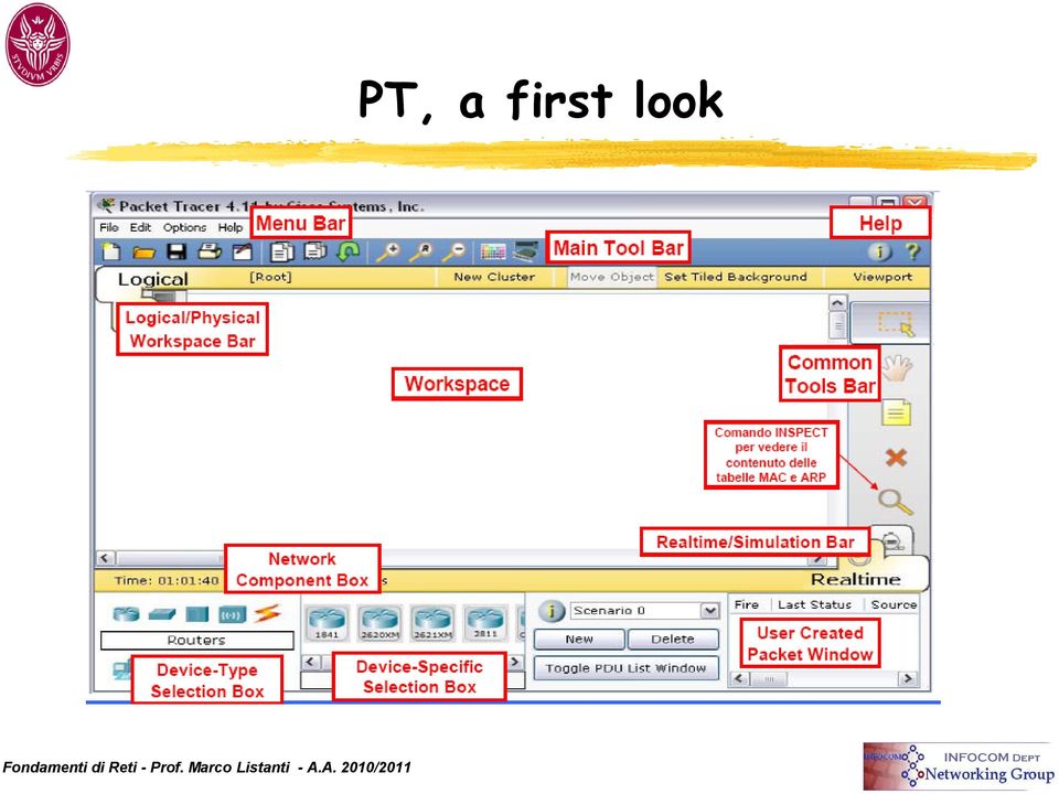
4 PT, a first look
5 Network Devices We can Use real network devices (Cisco) Create a new device Available devices are categorized in: Routers, Switches, Hubs (Repeaters), Wireless Devices (Access Point), End Devices (PCs, servers, printers,ipphone), WAN emulations (DSL e Cable Modem), customized devices
, WAN emulations (DSL e Cable Modem),")
6 How to create a device 4. Click on workspace. 1. Click on Select tool 2. Select a type of device 3. Choose a device


7 Tools: The Common Tools Bar Select tool : select an item on the workspace Move tool: to move the whole topology Note tool: to add a notice Delete tool: to remove links and devices

8 Empty device 3. Physical Tab 4. Modules 2. Click on Device 1. Select generic empty device, e.g. Router

, Fiber Gigabit Ethernet (FGE), etc 3.")
9 Adding modules to an empty device 4. Switch on the device 1. Switch off the device 4. To remove a module drag it to the module list 2. Choose the interface you want to install; e.g. Cable Gigabit Ethernet (CGE), Fiber Gigabit Ethernet (FGE), etc 3. Drag the module to an available slot on the device
, Fiber Gigabit Ethernet (FGE), etc 3.")
10 Connecting devices To connect two devices we need to choose: a suitable transmission medium (wired or wireless connection?) Correct interfaces Smart connection mode is also available: PT automatically selects the correct cable and interface
 Correct interfaces Smart connection mode is also")
11 Smart Connection 4. Click on first device. 1. Click Select tool 2. Click on Connection. 5. Click on second device. 3. Smart Connection.

12 Port Status Red means that the port is "down : it does not work! The default state of a router interface is "shutdown".

13 Port Labels Put the mouse cursor over the link to see which are the ports that the "Smart Connection" has used

14 Manual Connection Choose the correct cable Fiber if you want to use a Fiber Gigabit Ethernet interface Copper if you want to use a Copper Ethernet interface Copper Straight-Through if you are connecting an Ethernet end-device (PC or Router) to a switch Copper Cross-Over if you are directly connecting two enddevices (PC or Router) Click on devices and choose the correct interface
 Click on devices and choose the correct")

15 Configuring devices with PT (1/2) Packet Tracer provides a GUI to make basic configuration It also shows equivalent CLI commands Not used in this course


16 Configuring devices with PT (2/2) Packet Tracer emulates the Command Line Interface of Cisco-IOS Same commands of any Cisco device!!!

17 Configuring un Router
18 Management ports

19 How to use AUX and Console ports The console and AUX ports are used for management operations they are serial and asynchronous one of them is required for the initial router configuration (The console port is recommended) not all routers have an AUX port Once you have edited the initial configuration, the router can be connected to the network It is better to use the console port because it allows to display by default router startup, debugging and error messages It can also be used for recovery procedures (in case of disasters) or for password recovery.
 or for password")
20 Connection configuration with console port The console port is used to provide out-of-band access (for management operations) It is used for the initial configuration, troubleshooting, monitoring and disaster recovery procedures. To connect to a console port we have to use a rollover cable and a RJ-45 to DB-9 adapter. The PC must support terminal emulation, with software such as HyperTerminal


21 Establishing a HyperTerminal session(1/2) A console terminal is an ASCII terminal or a PC running terminal emulation on the console port The default parameters for the console port are 9600 baud, 8 data bits, no parity, 1 stop bit and no flow control, the console port does not support hardware flow control The steps required are Connecting the terminal using a rollover cable (using the appropriate adapter RJ-45 to DB-9) Configuring as indicated above the terminal or the terminal emulator on the PC

22 Establishing a HyperTerminal session (2/2) 1. Configure the terminal emulation on the PC with: The appropriate COM port 9600 baud 8 data bits No parity 1 stop bit No flow control 2. Connect the connector RJ-45 of the rollover cable to the router console port 3. Connect the other end of the cable to the adapter RJ- 45 to DB-9 4. Attach the DB-9 side of the adapter to the PC.

23 Terminal Session on PT (1/3) Connecting the terminal (the PC) with the Router 3. Connect the PC with the Router 2. Click on Console 1. Click on Connections

24 Terminal Session on PT (2/3) Opening a Terminal Session 2. Click on Desktop 3. Click on Terminal 1. Click on PC 4. Open the session

25 Terminal Session on PT (3/3) Now you are connected with the Router You can use the CLI of the Router
26 Cisco IOS A router or a switch cannot work without an operating system The Cisco IOS operating system is the software architecture of Cisco routers and Catalyst switches The Cisco IOS provides the following services: Basic functions of routing and switching Secure and reliable access to network resources
27 CLI (1/2) The Cisco IOS uses a command line interface (CLI) Two possible ways of accessing Console session uses a low-speed serial connection or a modem it is not necessary that the router has configured the network services Telnet session To establish a Telnet session with a router at least one interface must be configured with an IP address and the virtual terminal must be configured for login and password
28 CLI (2/2) The CLI uses a hierarchical structure Each level allows to accomplish certain tasks The sessions EXEC (executive command, the interpreter of IOS commands) supports two levels of access User EXEC mode Privileged EXEC mode or enable mode The user EXEC mode allows only a limited number of basic commands for monitoring functions ("view only" mode) It does not allow any command that could change the router configuration It is recognized for the prompt >" The Privileged EXEC mode allows to use the whole set of commands: It is possible to set a password for accessing Privileged EXEC It is recognized for the prompt "#"
29 Levels of access to the commands (1/3) Routers have two access levels User EXEC mode Privileged EXEC mode To access the complete set of commands you must enter in the Privileged EXEC mode At the prompt ">" you have to write the command "enable The password to enter in the privileged mode can be set using the commands "enable password" or "enable secret if you use both commands the latter has priority When the login has been completed the prompt changes to "#"
30 Levels of access to the commands (2/3) The configuration via CLI for a Cisco router is always done in global configuration mode Other configuration modes (not global) are accessible from the global configuration mode To access the global configuration mode you have to use the command configure terminal Router#configure terminal Router(config)# From the global configuration mode you can configure Interfaces Subinterfaces Routing Protocols Access-list

31 Levels of access to the commands (3/3) To return to the USER EXEC mode you can use the command "disable" or "exit" To return to the privileged EXEC mode from the global configuration one use exit o Ctrl-Z This command can also be used to return directly to the privileged mode from anywhere in the global configuration mode

32 Command modes of the CLI
33 Aid in the router CLI Writing? in the user EXEC or in the privileged mode it will be displayed the list of available commands After "-More-" at the end of the display, the screen will display other commands Pressing ENTER, we will see the next line, any other key causes the return to the prompt You can also enter in the privileged mode using the command "ena Example: Suppose that we have to set the clock and we don t know the command Use "?" To find the command to set the clock Check the syntax to change the time Set the time using hours, minutes and seconds Press "Ctrl-P" or "up arrow" to repeat the last command The symbol ^ indicates an error The tab key completes a command
34 Naming the router A router should be named with a "unique name To assign a name from the global config Router(config)#hostname Tokyo Tokyo(config)#
35 Reserved access (1/4) The access to the router can be limited by configuring passwords Passwords can be configured to restrict the access: 1. to the router from the console port 2. to the router from a virtual terminal line (vty), eg. access via Telnet 3. to the Privileged EXEC mode To configure a password for the access via console: Router(config)#line console 0 Router(config-line)#password <password> Router(config-line)#login
36 Reserved access (2/4) To configure a password for the access via the virtual terminal line: Router(config)#line vty 0 4 Router(config-line)#password <password> Router(config-line)#login
37 Reserved access (3/4) To configure a password for the access to the Privileged EXEC mode: There are two possible solutions: 1. Using the command enable password Router(config)#enable password <password> In this case the password is stored unencrypted in the configuration file (it is visible using the command show running-config o show startup-config )
38 Reserved access (4/4) You can encrypt your password by enabling the service password encryption: Router(config)#service password-encryption 2. Using the command enable secret Router(config)#enable secret <password> The password is encrypted in the configuration file The encryption algorithm used by the command enable secret is more robust than the one used by the password encryption service
39 The command show (1/2) It is used to display some information related to the router It is available in User EXEC or in Privileged EXEC (with different access levels to the information) Examples: show interfaces shows all statistics of the interfaces show controllers serial displays specific information about the hardware of the interface show clock shows the time set in the router show hosts shows the cached list of host names and addresses show users shows all users connected to the router show history shows the history of used commands
40 The command show (2/2) show flash shows information on flash memory and on flies sored on it show version shows router and IOS information show ARP shows the ARP table of the router show protocol shows global and local (each interface) states of Layer 3 protocols show startup-configuration shows the configuration stored in the NVRAM show running-configuration shows the configuration currently used and stored in the RAM
41 Configuring an Ethernet interface Enter in Global Configuration mode Enter in the Specific Configuration mode We want to configure the interface gigabitethernet 0/0 Configure the IP address and the Subnet Mask Enable the interface It is disabled (shutdown) by default Router#configure terminal Router(config)#interface gigabitethernet 0/0 Router(config-if)#ip address Router(config-if)#no shutdown
42 Interface description (1/3) It is useful to assign a description to an interface The description does not affect interface operation as it is just a comment. The descriptions may include for example: the name of the network connected to the interface the location of the interface Interface descriptions are inserted with the command "description" in the interface configuration section

43 Interface description (2/3)
44 Interface description (3/3) Steps of the procedure (from Privileged EXEC): 1. Enter in global configuration mode with the command "configure terminal 2. Enter in the specific mode interface with: (for example) "Interface ethernet0 3. Use the command "description" followed by the information that should be displayed 4. Use the command "Ctrl-Z" to return to the Privileged EXEC mode
45 Configuring the Default Gateway of the PC Click on the PC and then click on the Config tab In GLOBAL Settings, you can change the name of the PC and insert the IP address of the gateway.

46 Configuring the IP address of the PC Click on FastEthernet in INTERFACE to configure the IP address and Subnet Mask.
47 Configuration files Running-config file: contains the current configuration Startup-config file: contains the last saved configuration in the NVRAM (and reloaded after the restart) To change the router configuration you have to access the required mode and enter the command To verify the changes "show running-config"
48 Example of a simple configuration
49 Saving the configuration To return to the previous configuration: Disable the command with "no command_name Reload the original configuration file from the NVRAM Reload a configuration file stored on a TFTP server To remove the startup-config file use the command "erase startup-config" and reboot the router (you enter in the setup mode) To save the changes (reloaded after the restart) copy the configuration file in the NVRAM using the command "copy running-config startup-config Router# copy running-config startup-config
50 Checking Connectivity Packet Tracer allows to check network connectivity in different ways. Realtime Mode: opening a command prompt from the desktop PC and trying to ping as in the real world. Simulation Mode: It is possible to create a simulation to see packets along their path and understand how they are processed
51 Chcking Connectivity in Realtime Mode In Realtime mode, select Desktop from the tabbed interface. Click the Command Prompt icon to open a command prompt from the PC.
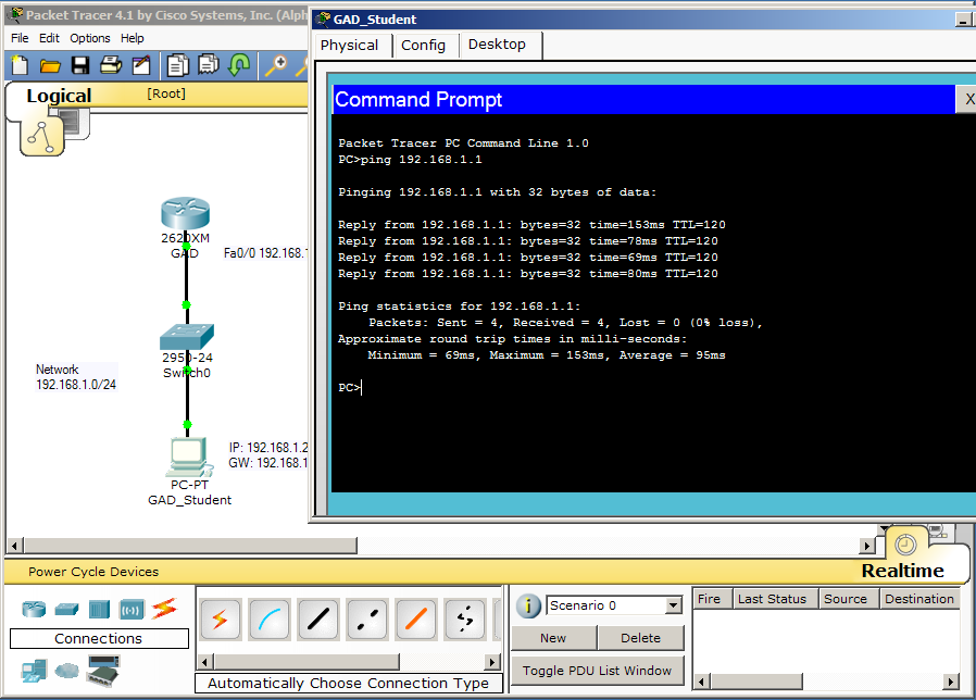
52 Ping the Default Gateway Ping the Default Gateway
53 Configuring a router using a Telnet Session Remote devices can be configured by means of a Telnet session The device must be reachable from your PC Open the Command Prompt Open the Telnet Session You are on the Router s CLI
54 Opening a Telnet Session Write the command telnet IP address
55 Changing the addressing scheme We want to change the address of the subnetwork from /24 to /24 When we change the address of interface GigabitEthernet 0/0 we will loose the connection Change PC address properly and reconnect to the router to save changes

56 Scenario 2 Open file Lesson1-Scenario2.pkt You can only access PC Rome Look at the configuration of the PC Try to access Router Rome from Telnet Discover its configuration
57 Discovering Network configuration What is the IP address of Router Milan? Can Router Milan be reached from PC Rome? Check by a ping or trace route Why? How to access Router Milan to configure it?

58 Telent bounce Once you have accessed a device, you can open a telnet session toward onther device in the network, and so on PC Rome can reach Router Rome but not Router Milan Router Rome can reach Router Milan!!!
59 Why does it succeed? PC Rome Router Rome Router Milan TELNET TCP IP MAC PHY PC Rome TELNET TCP IP MAC PHY DA IP SA MAC PHY R. Rom. PC Rom. Telnet TELNET TCP IP MAC PHY Router Rome IP MAC PHY DA IP SA MAC PHY DA R. Mil. PC Rom. Telnet IP SA TELNET TCP IP MAC PHY R. Mil. R. Rom. Telnet Router Milan TELNET TCP IP MAC PHY Works Doesn t Work
3.1 Connecting to a Router and Basic Configuration
 3.1 Connecting to a Router and Basic Configuration Objective This lab will focus on the ability to connect a PC to a router in order to establish a console session and observe the user interface. A console
Procedure: You can find the problem sheet on Drive D: of the lab PCs. Part 1: Router & Switch
 University of Jordan Faculty of Engineering & Technology Computer Engineering Department Computer Networks Laboratory 907528 Lab. 2 Network Devices & Packet Tracer Objectives 1. To become familiar with
Configuring a Router
 CHAPTER 3 Configuring a Router This chapter provides information and commands concerning the following topics: Configuring a router, specifically: Names Passwords Interfaces MOTD banners IP host tables
Note: This case study utilizes Packet Tracer. Please see the Chapter 5 Packet Tracer file located in Supplemental Materials.
 Note: This case study utilizes Packet Tracer. Please see the Chapter 5 Packet Tracer file located in Supplemental Materials. CHAPTER 5 OBJECTIVES Configure a router with an initial configuration. Use the
Lab 1.2.3 Review of Basic Router Configuration with RIP. Objective. Background / Preparation. General Configuration Tips
 Lab 1.2.3 Review of Basic Router Configuration with RIP Objective Cable and configure workstations and routers Setup IP addressing scheme using Class B networks Configure Routing Information Protocol (RIP)
Connect the Host to attach to Fast Ethernet switch port Fa0/2. Configure the host as shown in the topology diagram above.
 Lab 1.2.2 Capturing and Analyzing Network Traffic Host Name IP Address Fa0/0 Subnet Mask IP Address S0/0/0 Subnet Mask Default Gateway RouterA 172.17.0.1 255.255.0.0 192.168.1.1 (DCE) 255.255.255.0 N/A
Lab 2 - Basic Router Configuration
 CS326 Fall 2001 Room: PAI 5.48 Name: Lab 2 - Basic Router Configuration In this lab you will learn: the various configuration modes of Cisco 2621 routers how to set up IP addresses for such routers how
ENetwork Basic Configuration PT Practice SBA
 ENetwork Basic Configuration PT Practice SBA A few things to keep in mind while completing this activity: 1. Do not use the browser Back button or close or reload any exam windows during the exam. 2. Do
Lab 3 Routing Information Protocol (RIPv1) on a Cisco Router Network
 on a Cisco Router Network") Lab 3 Routing Information Protocol (RIPv1) on a Cisco Router Network CMPE 150 Fall 2005 Introduction Today you are going to be thrown into using Cisco s Internetwork Operating System (IOS) to configure
Lab 3 Routing Information Protocol (RIPv1) on a Cisco Router Network CMPE 150 Fall 2005 Introduction Today you are going to be thrown into using Cisco s Internetwork Operating System (IOS) to configure
Cisco Router Configuration Basics. Scalable Infrastructure Workshop
 Cisco Router Configuration Basics Scalable Infrastructure Workshop Router Components p RAM n Holds operating system, data structures, packet buffers, ARP cache, and routing tables n Reset on reload n Router
Skills Assessment Student Training Exam
 Skills Assessment Student Training Exam Topology Assessment Objectives Part 1: Initialize Devices (8 points, 5 minutes) Part 2: Configure Device Basic Settings (28 points, 30 minutes) Part 3: Configure
Angelos Stavrou. OF COURSE there is no Magic so lets see show things work in practice...
 Cisco Inter-network Operating System (IOS) A short guide for the NetAdmin Angelos Stavrou Let's start out at the very beginning with the question: "What is a Command?" The most important thing to understand
Configuring the Switch with the CLI-Based Setup Program
 APPENDIX D Configuring the Switch with the CLI-Based Setup Program This appendix provides a command-line interface (CLI)-based setup procedure for a standalone switch. For product overview information,
Objectives. Router as a Computer. Router components and their functions. Router components and their functions
 2007 Cisco Systems, Inc. All rights reserved. Cisco Public Objectives Introduction to Routing and Packet Forwarding Routing Protocols and Concepts Chapter 1 Identify a router as a computer with an OS and
Introduction to Routing and Packet Forwarding. Routing Protocols and Concepts Chapter 1
 Introduction to Routing and Packet Forwarding Routing Protocols and Concepts Chapter 1 1 1 Objectives Identify a router as a computer with an OS and hardware designed for the routing process. Demonstrate
Lab 8.3.3b Configuring a Remote Router Using SSH
 Lab 8.3.3b Configuring a Remote Router Using SSH Objectives Use SDM to configure a router to accept SSH connections. Configure SSH client software on a PC. Establish a connection to a Cisco ISR using SSH
AN ANALYTICAL STUDY OF INTERNET AND INTRANET CONNECTIONS AND CONFIGURATIONS IN ISP
 AN ANALYTICAL STUDY OF INTERNET AND INTRANET CONNECTIONS AND CONFIGURATIONS IN ISP Mst. Najnin Sultana, Abu Jafar Md. Masud Karim Daffodil International University, Dhaka, Bangladesh E-mail: [email protected]
Packet Tracer 3 Lab VLSM 2 Solution
 Packet Tracer 3 Lab VLSM 2 Solution Objective Create a simulated network topology using Packet Tracer Design an IP addressing scheme using a Class B subnetwork address and VLSM Apply IP addresses to the
PT Activity: Configure Cisco Routers for Syslog, NTP, and SSH Operations
 PT Activity: Configure Cisco Routers for Syslog, NTP, and SSH Operations Instructor Version Topology Diagram Addressing Table Device Interface IP Address Subnet Mask Default Gateway Switch Port R1 FA0/1
Lab: Basic Router Configuration
 Topology Diagram Addressing Table Device Interface IP Address Subnet Mask Def. Gateway R1 Fa0/0 192.168.1.1 255.255.255.0 N/A S0/0/0 192.168.2.1 255.255.255.0 N/A R2 Fa0/0 192.168.3.1 255.255.255.0 N/A
Lab 7.2.9 Load Balancing Across Multiple Paths
 Lab 7.2.9 Load Balancing Across Multiple Paths Objective Configure Load balance across multiple paths. Observe the load balancing process. Background/Preparation Cable a network similar to the one in the
Lab 5.3.9b Managing Router Configuration Files Using TFTP
 Lab 5.3.9b Managing Router Configuration Files Using TFTP Device Host Name Interface IP Address Subnet Mask R1 R1 Fast Ethernet 0/0 172.17.0.1 255.255.0.0 Objectives Download and install TFTP server software.
LAB THREE STATIC ROUTING
 LAB THREE STATIC ROUTING In this lab you will work with four different network topologies. The topology for Parts 1-4 is shown in Figure 3.1. These parts address router configuration on Linux PCs and a
Router Lab Reference Guide
 Router Lab Reference Guide 1 PURPOSE AND GOALS The routing lab allows testing different IP-related protocols and solutions in a close to live environment. You can learn how to configure Cisco routers and
Lab 8.3.1.2 Configure Basic AP Security through IOS CLI
 Lab 8.3.1.2 Configure Basic AP Security through IOS CLI Estimated Time: 30 minutes Number of Team Members: Students will work in teams of two. Objective In this lab, the student will learn the following
Lab 5.3.5 Configuring Basic Router Settings with the Cisco IOS CLI
 Lab 5.3.5 Configuring Basic Router Settings with the Cisco IOS CLI Device Host Name Interface IP address Subnet mask R1 R1 Serial 0/0/0 (DCE) 172.17.0.1 255.255.0.0 FastEthernet 0/0 172.16.0.1 255.255.0.0
CCNA Discovery 4.1.3 Working at a Small to Medium Business or ISP Student Packet Tracer Lab Manual
 4.1.3 Working at a Small to Medium Business or ISP Student Packet Tracer Lab Manual This document is exclusive property of Cisco Systems, In Permission is granted to print and copy this document for non-commercial
Lab 3.1.2 Creating a Logical Network Diagram
 Lab 3.1.2 Creating a Logical Network Diagram Objectives Use router and switch commands to obtain information about an existing network. Use Cisco Network Assistant to obtain information about an existing
APNIC Members Training Course Security workshop. 2-4 July, 2008. Port Vila Vanuatu. In conjunction with PACNOG 4
 APNIC Members Training Course Security workshop 2-4 July, 2008 Port Vila Vanuatu In conjunction with PACNOG 4 Router device security lab 1. APNIC s remote lab In these exercises you will be remotely accessing
Lab 1.4.1 Introductory Lab 1 - Getting Started and Building Start.txt
 Lab 1.4.1 Introductory Lab 1 - Getting Started and Building Start.txt Objective This lab may introduce new CCNP lab equipment and certain IOS features. This introductory activity also describes how to
- Basic Router Security -
 1 Enable Passwords - Basic Router Security - The enable password protects a router s Privileged mode. This password can be set or changed from Global Configuration mode: Router(config)# enable password
Lab 4.2.4 Advanced Telnet Operations
 Lab 4.2.4 Advanced Telnet Operations Objective Use the telnet command to remotely access other routers. Verify that the application layer between the source and the destination is working properly. Suspend
Configuring the Switch with the CLI Setup Program
 APPENDIXC Configuring the Switch with the CLI Setup Program This appendix provides a command-line interface (CLI) setup procedure for a standalone switch. To set up the switch by using Express Setup, see
LAB MANUAL for Computer Network
 LAB MANUAL for Computer Network CSE-310 F Computer Network Lab L T P - - 3 Class Work : 25 Marks Exam : 25 MARKS Total : 50 Marks This course provides students with hands on training regarding the design,
LAB Configuring NAT. Objective. Background/Preparation
 LAB Configuring NAT Objective Configure a router to use network address translation (NAT) to convert internal IP addresses, typically private addresses, into outside public addresses. Configure static
Chapter 8 Lab B: Configuring a Remote Access VPN Server and Client
 Chapter 8 Lab B: Configuring a Remote Access VPN Server and Client Topology Note: ISR G2 devices have Gigabit Ethernet interfaces instead of FastEthernet Interfaces. All contents are Copyright 1992 2012
Cisco ISE Command-Line Interface
 This chapter provides information on the Cisco Identity Services Engine (Cisco ISE) command-line interface (CLI) that you can use to configure and maintain Cisco ISE. Cisco ISE Administration and Configuration
Basic Router and Switch Instructions (Cisco Devices)
") Basic Router and Switch Instructions (Cisco Devices) Basic Device Connection 1. Connect to the device via the console cable (light blue cable) and the use of a terminal program (Windows Hyperterminal,
Basic Router and Switch Instructions (Cisco Devices) Basic Device Connection 1. Connect to the device via the console cable (light blue cable) and the use of a terminal program (Windows Hyperterminal,
Basic Configuration of the Cisco 12000 Series Internet Router
 CHAPTER 2 Basic Configuration of the Cisco 12000 Series Internet Router This chapter describes how to boot and configure the Cisco 12000 Series Internet Router. It discusses the following subjects: Cisco
Connecting the DG-102S VoIP Gateway to your network
 Contents of Package: DG-102S VoIP Station Gateway Power adapter CD-ROM, including User s Manual Quick Install Guide Requirements: RS-232 Console Cable Two RJ-45 CAT-5 Straight-Through Cables For more information
CISCO CATALYST 3550 Series Switches
 CISCO CATALYST 3550 Series Switches The switches that belong to this series are stackable and are multilayer switches that provide QoS, high availability and security that are responsible for enhancing
PT Activity 8.1.2: Network Discovery and Documentation Topology Diagram
 Topology Diagram All contents are Copyright 1992 2007 Cisco Systems, Inc. All rights reserved. This document is Cisco Public Information. Page 1 of 6 Addressing Table Device Interface IP Address Subnet
USER GUIDE. Ethernet Configuration Guide (Lantronix) P/N: 2900-300321 Rev 6
 P/N: 2900-300321 Rev 6") KRAMER ELECTRONICS LTD. USER GUIDE Ethernet Configuration Guide (Lantronix) P/N: 2900-300321 Rev 6 Contents 1 Connecting to the Kramer Device via the Ethernet Port 1 1.1 Connecting the Ethernet Port Directly
KRAMER ELECTRONICS LTD. USER GUIDE Ethernet Configuration Guide (Lantronix) P/N: 2900-300321 Rev 6 Contents 1 Connecting to the Kramer Device via the Ethernet Port 1 1.1 Connecting the Ethernet Port Directly
Lab 5.3.8 Configuring PAT with SDM and Static NAT using Cisco IOS Commands
 Lab 5.3.8 Configuring PAT with SDM and Static NAT using Cisco IOS Commands Device Host Name Interface IP Address Subnet Mask R1 CustomerRouter Serial 0/0/0 (DTE) 209.165.200.225 255.255.255.224 Fast Ethernet
Cisco Configuration Professional Quick Start Guide
 Cisco Configuration Professional Quick Start Guide April 29, 2011 This document explains how to start using Cisco Configuration Professional Express (Cisco CP Express) and Cisco Configuration Professional
Password Recovery Procedure for the Cisco 3600 and 3800 Series Routers
 Password Recovery Procedure for the Cisco 3600 and 3800 Series Routers Document ID: 22189 Contents Introduction Prerequisites Requirements Components Used Related Products Conventions Step by Step Procedure
ICND1 Lab Guide. 100-101 Interconnecting Cisco Networking Devices Part 1 Version 2.0. Labs powered by
 ICND1 Lab Guide 100-101 Interconnecting Cisco Networking Devices Part 1 Version 2.0 ii Interconnecting Cisco Networking Devices Part 1 100-101 Lab Guide LM20130929/BV2.01 iii 25 Century Blvd. Ste. 500
Configuring a Cisco 2509-RJ Terminal Router
 created by: Rainer Bemsel Version 1.0 Dated: Dec/08/2012 For my Cisco LAB, I ve purchased a used Cisco 2509-RJ with RJ45-RJ45 roll-over cables. This TechTip shows my configuration setup, so you can easily
Device Interface IP Address Subnet Mask Default Gateway
 Felix Rohrer Topology Diagram Addressing Table Device Interface IP Address Subnet Mask Default Gateway S1 VLAN 99 192.168.99.11 255.255.255.0 192.168.99.1 S2 VLAN 99 192.168.99.12 255.255.255.0 192.168.99.1
This techno knowledge paper can help you if: You need to setup a WAN connection between a Patton Router and a NetGuardian.
 Problem: Patton / 240T WAN Setup Platform: NetGuardian 240T This TKP is a guide to setting up a PPP to T1 WAN connection between a Patton Model 2603 Router and a NetGuardian 240T. The example in this guide
How To Set Up A Netvanta For A Pc Or Ipad (Netvanta) With A Network Card (Netvina) With An Ipa (Net Vanta) And A Ppl (Netvi) (Netva)
 With A Network Card (Netvina) With An Ipa (Net Vanta) And A Ppl (Netvi) (Netva)") VPN WAN LAN PWR STAT TD RD TD RD TD RD VPN WAN LAN PWR STAT TD RD TD RD TD RD NetVanta 3200 NetVanta 3200 NetVanta Series (with T1/FT1 or T1/FT1 + DSX-1 Network Interface Module) Quick Configuration Guide
VPN WAN LAN PWR STAT TD RD TD RD TD RD VPN WAN LAN PWR STAT TD RD TD RD TD RD NetVanta 3200 NetVanta 3200 NetVanta Series (with T1/FT1 or T1/FT1 + DSX-1 Network Interface Module) Quick Configuration Guide
USER MANUAL GUIMGR Graphical User Interface Manager for FRM301/FRM401 Media Racks
 USER MANUAL GUIMGR Graphical User Interface Manager for FRM301/FRM401 Media Racks CTC Union Technologies Co., Ltd. Far Eastern Vienna Technology Center (Neihu Technology Park) 8F, No. 60 Zhouzi St. Neihu,
Connecting to the Firewall Services Module and Managing the Configuration
 CHAPTER 3 Connecting to the Firewall Services Module and This chapter describes how to access the command-line interface and work with the configuration. This chapter includes the following sections: Connecting
Basic Software Configuration Using the Cisco IOS Command-Line Interface
 Basic Software Configuration Using the Cisco IOS Command-Line Interface This document describes how to use the Cisco IOS command-line interface (CLI) to perform a basic software configuration for your
Lab 4.5.2 Diagramming Intranet Traffic Flows
 Lab 4.5.2 Diagramming Intranet Traffic Flows Objective Device Designation Device Name Address Subnet Mask Discovery Server Business Services 172.17.1.1 255.255.0.0 R1 FC-CPE-1 Fa0/1 172.17.0.1 Fa0/0 10.0.0.1
CHAPTER 3 STATIC ROUTING
 CHAPTER 3 STATIC ROUTING This chapter addresses the end-to-end delivery service of IP and explains how IP routers and hosts handle IP datagrams. The first section discusses how datagrams are forwarded
Lab 8.4.3b Managing Cisco IOS images with ROMMON and TFTP
 Lab 8.4.3b Managing Cisco IOS images with ROMMON and TFTP Host Device Name Interface IP Address Subnet Mask R1 R1 Fast Ethernet 0/0 172.17.0.1 255.255.0.0 Objectives Analyze the Cisco IOS image and router
50-Port 10/100/1000Mbps with 4 Shared SFP. Managed Gigabit Switch WGSW-50040. Quick Installation Guide
 50-Port 10/100/1000Mbps with 4 Shared SFP Managed Gigabit Switch WGSW-50040 Quick Installation Guide Table of Contents 1. Package Content... 3 2. Switch Management... 4 3. Requirements... 5 4. Terminal
Cisco Router Configuration Tutorial
 Cisco Router Configuration Tutorial Cisco Inter-network Operating System: Cisco IOS Modes of Operation The Cisco IOS software provides access to several different command modes. Each command mode provides
Password Recovery Procedure for the Cisco 806, 826, 827, 828, 831, 836, 837 and 881 Series Routers
 Password Recovery Procedure for the Cisco 806, 826, 827, 828, 831, 836, 837 and 881 Series Routers Document ID: 12065 Contents Introduction Prerequisites Requirements Components Used Related Products Conventions
Routing Protocols and Concepts Chapter 2 Conceitos de protocolos de Encaminhamento Cap 2
 Static Routing Routing Protocols and Concepts Chapter 2 1 1 Objectives Define the general role a router plays in networks. Describe the directly connected networks, different router interfaces Examine
Password Recovery Procedure for the Cisco Catalyst 2948G L3, 4840G, and 4908G L3 Switch Routers
 Password Recovery Procedure for the Cisco Catalyst 2948G L3, 4840G, and 4908G L3 Switch Routers Document ID: 12738 Contents Introduction Before You Begin Conventions Prerequisites Step by Step Procedure
[HOW TO RECOVER AN INFINITI/EVOLUTION MODEM IDX3.0.0.0] 1
![[HOW TO RECOVER AN INFINITI/EVOLUTION MODEM IDX3.0.0.0] 1](/thumbs/24/2694327.jpg "[HOW TO RECOVER AN INFINITI/EVOLUTION MODEM IDX3.0.0.0] 1") [HOW TO RECOVER AN INFINITI/EVOLUTION MODEM IDX3.0.0.0] 1 How to Recover an infiniti/evolution Modem Software Reference idx 3.0.0.0 (12.0.0.0) Updated: November 17 th 2011 Overview Recovery Procedures
[HOW TO RECOVER AN INFINITI/EVOLUTION MODEM IDX3.0.0.0] 1 How to Recover an infiniti/evolution Modem Software Reference idx 3.0.0.0 (12.0.0.0) Updated: November 17 th 2011 Overview Recovery Procedures
http://computernetworkingnotes.com/ccna-study-guide/cisco-ios-naming-convention-explainedwith-examples.html
 IOS is the most critical part of any cisco device. We should always keep a backup copy of IOS to deal with any unwanted situation. In this article I will explain the backup and restore process of IOS in
CCNA Exploration 4.0: (II) Routing Protocols and Concepts. Chapter 1: Introduction to Routing and Packet Forwarding
 Routing Protocols and Concepts. Chapter 1: Introduction to Routing and Packet Forwarding") Http://elmaestrodelared.blogspot.com CCNA Exploration 4.0: (II) Routing Protocols and Concepts Chapter 1: Introduction to Routing and Packet Forwarding 1. If a router cannot find a valid configuration
Http://elmaestrodelared.blogspot.com CCNA Exploration 4.0: (II) Routing Protocols and Concepts Chapter 1: Introduction to Routing and Packet Forwarding 1. If a router cannot find a valid configuration
Lab 8.4.3a Managing Cisco IOS Images with TFTP
 Lab 8.4.3a Managing Cisco IOS Images with TFTP Host Device Name Interface IP Address Subnet Mask R1 R1 Fast Ethernet 0/0 172.17.0.1 255.255.0.0 Objectives Analyze the Cisco IOS image and router flash memory.
Lab - Using IOS CLI with Switch MAC Address Tables
 Topology Addressing Table Objectives Device Interface IP Address Subnet Mask Default Gateway R1 G0/1 192.168.1.1 255.255.255.0 N/A S1 VLAN 1 192.168.1.11 255.255.255.0 192.168.1.1 S2 VLAN 1 192.168.1.12
Lab 5.3.7 Configuring DHCP with SDM and the Cisco IOS CLI
 Lab 5.3.7 Configuring DHCP with SDM and the Cisco IOS CLI Device Host Name Interface IP Address Subnet Mask R1 Customer Serial 0/0/1 (DTE) 209.165.200.225 255.255.255.224 Fast Ethernet 0/0 192.168.1.1
Lab 4.5.4 Diagramming External Traffic Flows
 Lab 4.5.4 Diagramming External Traffic Flows Device Designation Device Name Address Subnet Mask Discovery Server Business Services 172.17.1.1 255.255.0.0 R1 R2 R3 FC-CPE-1 FC-CPE-2 ISP Fa0/1 172.17.0.1
Objectives. Background. Required Resources. CCNA Security
 Chapter 8 Lab B, Configuring a Remote Access VPN Server and Client Topology IP Addressing Table Device Interface IP Address Subnet Mask Default Gateway Switch Port R1 FA0/1 192.168.1.1 255.255.255.0 N/A
Objectives Understand Cisco IOS system architecture components. Work with the Cisco IOS Command Line Interface (CLI) and common commands.
 and common commands.") Objectives Understand Cisco IOS system architecture components. Work with the Cisco IOS Command Line Interface (CLI) and common commands. Learn about Cisco IOS troubleshooting techniques. Understand upgrading
Objectives Understand Cisco IOS system architecture components. Work with the Cisco IOS Command Line Interface (CLI) and common commands. Learn about Cisco IOS troubleshooting techniques. Understand upgrading
Figure 1 - T1/E1 Internet Access
 Page 1 of 17 TECH NOTE Configuring T1 and E1 Internet Access in AOS Overview This guide explains how to configure an Adtran Operating System (AOS) router for T1/E1 Internet access. You should use this
Password Recovery Procedure for the Cisco 2900 Series Integrated Services Router
 Password Recovery Procedure for the Cisco 2900 Series Integrated Services Router Document ID: 112033 Contents Introduction Prerequisites Requirements Components Used Related Products Conventions Step by
Connecting Hosts and Routers
 Connecting Hosts and s Nicolas Christin University of Virginia Prepared for the ITL Workshop, June 2001 Overview There are three issues involved in connecting PCs (hosts) and routers. First, setting up
NetVanta 3000 Series (with T1/FT1 or T1/FT1 with DSX-1 Network Interface Module)
") VPN WAN LAN PWR STAT TD RD TD RD TD RD VPN WAN LAN PWR STAT TD RD TD RD TD RD NetVanta 3000 Series (with T1/FT1 or T1/FT1 with DSX-1 Network Interface Module) Quick Configuration Guide 61200862L1-42A November
VPN WAN LAN PWR STAT TD RD TD RD TD RD VPN WAN LAN PWR STAT TD RD TD RD TD RD NetVanta 3000 Series (with T1/FT1 or T1/FT1 with DSX-1 Network Interface Module) Quick Configuration Guide 61200862L1-42A November
Lab 7.2.9 Load Balancing Across Multiple Paths Instructor Version 2500
 Lab 7.2.9 Load Balancing Across Multiple Paths Instructor Version 2500 Objective onfigure Load balance across multiple paths. Observe the load balancing process. Background/Preparation able a network similar
Quick Start Guide. Cisco Small Business. 200E Series Advanced Smart Switches
 Quick Start Guide Cisco Small Business 200E Series Advanced Smart Switches Welcome Thank you for choosing the Cisco 200E series Advanced Smart Switch, a Cisco Small Business network communications device.
Building a Network in GNS3
 Building a Network in GNS3 In this tutorial, you will create a network in GNS3 between two routers, and each router will have one host connected to it. The ultimate goal is to route data between network
How to Configure Cisco 2600 Routers
 Helsinki University of Technology Department of Communications and Networking How to Configure Cisco 2600 Routers Juha Järvinen 10.6.2004 [email protected] Modified by Zhong Yunqiu 7.8.2008 Table
ZyWALL 5. Internet Security Appliance. Quick Start Guide Version 3.62 (XD.0) May 2004
 May 2004") ZyWALL 5 Internet Security Appliance Quick Start Guide Version 3.62 (XD.0) May 2004 Introducing the ZyWALL The ZyWALL 5 is the ideal secure gateway for all data passing between the Internet and the LAN.
ZyWALL 5 Internet Security Appliance Quick Start Guide Version 3.62 (XD.0) May 2004 Introducing the ZyWALL The ZyWALL 5 is the ideal secure gateway for all data passing between the Internet and the LAN.
Prestige 650R-31/33 Read Me First
 Prestige 650R-31/33 Read Me First Prestige Rear Panel Connections PORT DSL CONSOLE LAN 10/100M POWER Connect to a telephone jack using a telephone wire. CONNECTION Connect to a serial port (COM port) on
Telnet, Console and AUX Port Passwords on Cisco Routers Configuration Example
 Telnet, Console and AUX Port Passwords on Cisco Routers Configuration Example Document ID: 45843 Introduction Prerequisites Requirements Components Used Conventions Background Information Configure Passwords
Lab 1.5.1 Introductory Lab 1 Getting Started and Building Start.txt
 Lab 1.5.1 Introductory Lab 1 Getting Started and Building Start.txt Objective This lab will introduce to the student the CCNP lab equipment and certain IOS features that might be new. This introductory
Cisco CCNA Optional Semester 4 Labs Wide Area Networking LAB 1 T1 TSU WAN LINK OVERVIEW - Instructor Guide (Estimated time: 30 minutes)
") CNAP @ VCC 1 of 8 LAB 1 T1 TSU WAN LINK OVERVIEW - Instructor Guide (Estimated time: 30 minutes) Objectives: Understand the function of a T1 Service Unit (TSU) in network telecommunications Connect routers
CNAP @ VCC 1 of 8 LAB 1 T1 TSU WAN LINK OVERVIEW - Instructor Guide (Estimated time: 30 minutes) Objectives: Understand the function of a T1 Service Unit (TSU) in network telecommunications Connect routers
- The PIX OS Command-Line Interface -
 1 PIX OS Versions - The PIX OS Command-Line Interface - The operating system for Cisco PIX/ASA firewalls is known as the PIX OS. Because the PIX product line was acquired and not originally developed by
CCNA 2 Chapter 5. Managing Cisco IOS Software
 1 CCNA 2 Chapter 5 Managing Cisco IOS Software The default source for Cisco IOS Software depends on the hardware platform; most commonly, though, the router looks to the configuration commands that are
Configuring WAN Failover with a Cisco 881 Router and an AirLink ES440
 Configuring WAN Failover with a Cisco 881 Router and an AirLink ES440 When the AirLink ES440 is combined with a third-party router, the combined solution supports business continuity by providing primary
Packet Tracer - Connecting a Wired and Wireless LAN Topology
 Topology 2013 Cisco and/or its affiliates. All rights reserved. This document is Cisco Public. Page 1 of 5 Addressing Table Objectives Cloud Cable Modem Router0 Router1 WirelessRouter Part 1: Connect to
Lab 5.5.3 Developing ACLs to Implement Firewall Rule Sets
 Lab 5.5.3 Developing ACLs to Implement Firewall Rule Sets All contents are Copyright 1992 2007 Cisco Systems, Inc. All rights reserved. This document is Cisco Public Information. Page 1 of 8 Device Interface
CCNA Discovery 4.0.3.0 Networking for Homes and Small Businesses Student Packet Tracer Lab Manual
 4.0.3.0 Networking for Homes and Small Businesses Student Packet Tracer Lab Manual This document is exclusive property of Cisco Systems, Inc. Permission is granted to print and copy this document for non-commercial
Pre-lab and In-class Laboratory Exercise 10 (L10)
") ECE/CS 4984: Wireless Networks and Mobile Systems Pre-lab and In-class Laboratory Exercise 10 (L10) Part I Objectives and Lab Materials Objective The objectives of this lab are to: Familiarize students
ECE/CS 4984: Wireless Networks and Mobile Systems Pre-lab and In-class Laboratory Exercise 10 (L10) Part I Objectives and Lab Materials Objective The objectives of this lab are to: Familiarize students
CCNA Exploration 4.0.5.0 Routing Protocols and Concepts Student Lab Manual
 4.0.5.0 Routing Protocols and Concepts Student Lab Manual This document is exclusive property of Cisco Systems, Inc. Permission is granted to print and copy this document for non-commercial distribution
LAN / WAN Connection Of Instruments with Serial Interface By Using a Terminal Server
 Products: EFA with EFA Scan, DVRM and DVMD with Realtime Monitor or Stream Explorer DVMD-B1 LAN / WAN Connection Of Instruments with Serial Interface By Using a Terminal Server Remote control of test and
1 Basic Configuration of Cisco 2600 Router. Basic Configuration Cisco 2600 Router
 1 Basic Configuration of Cisco 2600 Router Basic Configuration Cisco 2600 Router I decided to incorporate the Cisco 2600 into my previously designed network. This would give me two seperate broadcast domains
CT5760 Controller and Catalyst 3850 Switch Configuration Example
 CT5760 Controller and Catalyst 3850 Switch Configuration Example Document ID: 116342 Contributed by Antoine KMEID and Serge Yasmine, Cisco TAC Engineers. Aug 13, 2013 Contents Introduction Prerequisites
100-101: Interconnecting Cisco Networking Devices Part 1 v2.0 (ICND1)
") 100-101: Interconnecting Cisco Networking Devices Part 1 v2.0 (ICND1) Course Overview This course provides students with the knowledge and skills to implement and support a small switched and routed network.
100-101: Interconnecting Cisco Networking Devices Part 1 v2.0 (ICND1) Course Overview This course provides students with the knowledge and skills to implement and support a small switched and routed network.
Understanding Interface Numbering and Cisco IOS Software Basics
 CHAPTER 1 and Cisco IOS Software Basics This chapter provides an overview of the interface numbering in the Cisco 2600 series, Cisco 3600 series, and Cisco 3700 series routers. It also describes how to
Lab 9.1.1 Organizing CCENT Objectives by OSI Layer
 Lab 9.1.1 Organizing CCENT Objectives by OSI Layer Objectives Organize the CCENT objectives by which layer or layers they address. Background / Preparation In this lab, you associate the objectives of
Comware versus Cisco IOS Command Guide
 Technical Marketing Engineering Routing and Switching Technology Routing and Switching Comware versus Cisco IOS Command Guide Technical Marketing Brief Revision v5 March 23, 2009 http://www.3com.com 3Com