USER INSTRUCTIONS. Installation Operation Maintenance. ERPN centrifugal pumps. Horizontal, End Suction
|
|
|
- Morris Berry
- 8 years ago
- Views:
Transcription
1 USER INSTRUCTIONS ERPN centrifugal pumps Horizontal, End Suction Installation Operation Maintenance Original Instructions PCN= , , (E)

2 Type: ERPN - Size: Frame Serial No: Customer: Customer Order No.: Equipment / Item No.: Pumped Liquid: Capacity: m 3 /h Minimum Capacity: m 3 /h Head: m Speed: U/min -1

3 CONTENTS PAGE 1.0 INTRODUCTION AND SAFETY GENERAL CE MARKING AND APPROVALS DISCLAIMER COPYRIGHT DUTY CONDITIONS SAFETY WARNING LABEL SPECIFIC MACHINE PERFORMANCE NOISE LEVEL CE DECLARATION TRANSPORT AND STORAGE CONSIGNMENT RECEIPT AND UNPACKING HANDLING LIFTING STORAGE RECYCLING AND END OF PRODUCT LIFE DESCRIPTION CONFIGURATION NOMENCLATURE DESIGN OF MAJOR PARTS PERFORMANCE AND OPERATING LIMITS INSTALLATION LOCATION PART ASSEMBLIES FOUNDATION INITIAL ALIGNMENT PIPING ELECTRICAL CONNECTIONS FINAL SHAFT ALIGNMENT CHECK COMMISSIONING START-UP, OPERATION AND SHUTDOWN PRECOMMISSIONING PROCEDURE PUMP LUBRICANTS IMPELLER CLEARANCE DIRECTION OF ROTATION GUARDING PRIMING AND AUXILIARY SUPPLIES STARTING THE PUMP OPERATION STOPPING AND SHUTDOWN HYDRAULIC, MECHANICAL AND ELECTRICAL DUTY MAINTENANCE GENERAL MAINTENANCE SCHEDULE SPARE PARTS RECOMMENDED SPARES FASTENER TORQUES SETTING IMPELLER CLEARANCE DISASSEMBLY EXAMINATION OF PARTS ASSEMBLY AUXILIARIES SEAL AND SEAL SYSTEMS CHANGING OF MECHANICAL SEAL FAULTS; CAUSES AND REMEDIES CERTIFICATION OTHER RELEVANT DOCUMENTATION AND MANUALS SUPPLEMENTARY USER INSTRUCTIONS CHANGE NOTES ADDITIONAL SOURCES OF INFORMATION ABBREVIATIONS Page 3 of 39

4 1.0 INTRODUCTION AND SAFETY 1.1 General These Instructions must always be kept close to product's operating location or directly with the product. Flowserve's products are designed, developed and manufactured with state-of-the-art technologies in modern facilities. The unit is produced with great care and commitment to continuous quality control, utilising sophisticated quality techniques, and safety requirements. Flowserve is committed to continuous quality improvement and being at service for any further information about the product in its installation and operation or about its support products, repair and diagnostic services. These instructions are intended to facilitate familiarization with the product and its permitted use. Operating the product in compliance with these instructions is important to help ensure reliability in service and avoid risks. The instructions may not take into account local regulations; ensure such regulations are observed by all, including those installing the product. Always coordinate repair activity with operations personnel, and follow all plant safety requirements and applicable safety and health laws/regulations. These instructions should be read prior to installing, operating, using and maintaining the equipment in any region worldwide. The equipment must not be put into service until all the conditions relating to safety noted in the instructions have been met. 1.2 CE marking and approvals It is a legal requirement that machinery and equipment put into service within certain regions of the world shall conform with the applicable CE Marking Directives covering Machinery and, where applicable, Low Voltage Equipment, Electromagnetic Compatibility (EMC), Pressure Equipment Directive (PED) and Equipment for Potentially Explosive Atmospheres (ATEX). Where applicable the Directives, and any additional Approvals, cover important safety aspects relating to machinery and equipment and the satisfactory provision of technical documents and safety instructions. Where applicable this document incorporates information relevant to these Directives. To establish Approvals and if the product itself is CE Marked check the serial number plate and the Certification. 1.3 Disclaimer Information in these User Instructions is believed to be reliable. In spite of all the efforts of Flowserve Corporation to provide sound and all necessary information the content of this manual may appear insufficient and is not guaranteed by Flowserve as to its completeness or accuracy. Flowserve manufactures products to exacting International Quality Management System Standards as certified and audited by external Quality Assurance organisations. Genuine parts and accessories have been designed, tested and incorporated into the products to help ensure their continued product quality and performance in use. As Flowserve cannot test parts and accessories sourced from other vendors the incorrect incorporation of such parts and accessories may adversely affect the performance and safety features of the products. The failure to properly select, install or use authorised Flowserve parts and accessories is considered to be misuse. Damage or failure caused by misuse is not covered by Flowserve's warranty. In addition, any modification of Flowserve products or removal of original components may impair the safety of these products in their use. 1.4 Copyright All rights reserved. No part of these instructions may be reproduced, stored in a retrieval system or transmitted in any form or by any means without prior permission of Flowserve. 1.5 Duty conditions This product has been selected to meet the specifications of your purchaser order. The acknowledgement of these conditions has been sent separately to the Purchaser. A copy should be kept with these instructions. The product must not be operated beyond the parameters specified for the application. If there is any doubt as to the suitability of the product for the application intended, contact Flowserve for advice, quoting the serial number. If the conditions of service on your purchase order are going to be changed (for example liquid pumped, temperature or duty) it is requested that the user seeks Flowserve s written agreement before start up. Page 4 of 39

5 1.6 Safety Summary of safety markings These user instructions contain specific safety markings where non-observance of an instruction would cause hazards. The specific safety markings are: This symbol indicates electrical safety instructions where non-compliance will involve a high risk to personal safety or the loss of life. This symbol indicates safety instructions where non-compliance would affect personal safety and could result in loss of life. This symbol indicates "hazardous and toxic fluid" safety instructions where non-compliance would affect personal safety and could result in loss of life. This symbol indicates safety instructions where non-compliance will involve some risk to safe operation and personal safety and would damage the equipment or property. This symbol indicates "strong magnetic field" safety instructions where non-compliance would affect personal safety, pacemakers, instruments or stored data sensitive to magnetic fields. This symbol indicates explosive atmosphere marking according to ATEX. It is used in safety instructions where non-compliance in the hazardous area would cause the risk of an explosion. This symbol is used in safety instructions to remind not to rub non-metallic surfaces with a dry cloth; ensure the cloth is damp. It is used in safety instructions where non-compliance in the hazardous area would cause the risk of an explosion. The sign is not a safety symbol but indicates an important instruction in the assembly process. This symbol indicates potential risks connected with extremely high temperatures. This symbol indicates potential risks connected with extremely low temperatures Personnel qualification and training All personnel involved in the operation, installation, inspection and maintenance of the unit must be qualified to carry out the work involved. If the personnel in question do not already possess the necessary knowledge and skill, appropriate training and instruction must be provided. If required the operator may commission the manufacturer / supplier to provide applicable training. Always co-ordinate repair activity with operations and health and safety personnel, and follow all plant safety requirements and applicable safety and health laws/regulations Safety action This is a summary of conditions and actions to help prevent injury to personnel and damage to the environment and to equipment. For products used in potentially explosive atmospheres section also applies. PREVENT EXCESSIVE EXTERNAL PIPE LOAD Do not use pump as a support for piping. Do not mount expansion joints so that their force, due to internal pressure, acts on the pump flange. ONLY CHECK DIRECTION OF MOTOR ROTATION WITH COUPLING ELEMENT/ PINS REMOVED Starting in reverse direction of rotation will damage the pump. ENSURE CORRECT LUBRICATION (See section 5 Commissioning, startup, operation and shutdown.) START THE PUMP WITH OUTLET VALVE PART OPENED (Unless otherwise instructed at a specific point in the user instructions.) This is recommended to avoid the risk of overloading and damaging the pump motor at full or zero flow. Pumps may be started with the valve further open only on installations where this situation cannot occur. Pump outlet valve shall be adjusted to comply with the duty following the run-up process (See section 5 Commissioning, startup, operation and shutdown). START THE PUMP WITH OUTLET VALVE FULLY OPEN This is recommended to avoid the risk of overloading and damaging the pump motor where greater power is taken at low or shut off flow. Pump outlet valve shall be adjusted to comply with the duty following the Page 5 of 39

6 run-up process (See section 5 Commissioning, startup, operation and shutdown). NEVER RUN THE PUMP DRY INLET VALVES TO BE FULLY OPEN WHEN PUMP IS RUNNING Running the pump at zero flow or below the recommended minimum flow continuously will cause damage to the seal. DO NOT RUN THE PUMP AT ABNORMALLY HIGH OR LOW FLOW RATES Operating at a flow rate higher than normal or at a flow rate with no back pressure on the pump may overload the motor and cause cavitation. Low flow rates may cause a reduction in pump/bearing life, overheating of the pump, instability and cavitation/vibration. When ambient temperatures are likely to drop below freezing point, the pump and any cooling and flushing arrangements must be drained or otherwise protected. HANDLING COMPONENTS Many precision parts have sharp corners and the wearing of appropriate safety gloves and equipment is required when handling these components. To lift heavy pieces above 25 kg (55 lbs) use a crane corresponding to the mass and in accordance with current local regulations. NEVER DO MAINTENANCE WORK WHILST THE UNIT IS CONNECTED TO POWER HAZARDOUS LIQUIDS When the pump is handling hazardous liquids care must be taken to avoid exposure to the liquid by appropriate sitting of the pump, limiting personnel access and by operator training. If the liquid is flammable and/or explosive strict safety procedures must be applied. Gland Packing must not be used when pumping hazardous liquids. DRAIN PUMP AND ISOLATE PIPEWORK BEFORE DISMANTLING THE PUMP The appropriate safety precautions should be taken where the pumped liquids are hazardous. FLUORO-ELASTOMERS (When fitted) When a pump has experienced temperatures over 250 C (482 ºF), partial decomposition of fluoroelastomers (example: Viton) will occur. In this condition these are extremely dangerous and skin contact must be avoided. GUARDS MUST NOT BE REMOVED WHILE PUMP IS OPERATIONAL THERMAL SHOCK Rapid changes in the temperature of the liquid within the pump can cause thermal shock, which can result in damage or breakage of components and should be avoided. NEVER APPLY HEAT TO REMOVE IMPELLER Trapped lubricant or vapour could cause an explosion. HOT AND COLD PARTS If hot or freezing components or auxiliary heating supplies can present a danger to operators, they must be shielded to avoid accidental contact. If complete protection is not possible, the machine access must be limited to maintenance staff only. Note: bearing housings must not be insulated and drive motors and bearings may be hot. If the temperature is greater than 68 C (155 F) or below 5 C (41 F) in a restricted zone, or exceeds local regulations, action as above shall be taken Products used in potentially explosive atmospheres Measures are required to: Avoid excess temperature Prevent build up of explosive mixtures Prevent the generation of sparks Prevent leakages Maintain the pump to avoid hazard The following instructions for pumps and pump units when installed in potentially explosive atmospheres must be followed to help ensure explosion protection. Both electrical and non-electrical equipment must meet the requirements of European Directive 94/9/EC Scope of compliance Use equipment only in the zone for which it is appropriate. Always check that the driver, drive coupling assembly, seal and pump equipment are suitably rated and/or certified for the classification of the specific atmosphere in which they are to be installed. Where Flowserve has supplied only the bare shaft pump, the Ex rating applies only to the pump. The Page 6 of 39

7 party responsible for assembling the pump set shall select the coupling, driver and any additional equipment, with the necessary CE Certificate/ Declaration of Conformity establishing it is suitable for the area in which it is to be installed. The output from a variable frequency drive (VFD) can cause additional heating affects in the motor and so, for pump sets with a VFD, the ATEX Certification for the motor must state that it covers the situation where electrical supply is from the VFD. This is particular requirement still applies even if the VFD is in a safe area Marking An example of ATEX equipment marking is shown below. The actual classification of the pump will be engraved on the nameplate. II 2 GD c IIC135ºC (T4) Equipment Group I = Mining II = Non-mining Category 2 or M2 = High level protection 3 = normal level of protection Gas and/or Dust G = Gas; D= Dust c = Constructional safety (in accordance with En ) Gas Group (Equipment Category 2 only) IIA Propane (Typical) IIB Ethylene (Typical) IIC Hydrogen (Typical) Maximum surface temperature (Temperature Class) (see section ) Avoiding excessive surface temperatures ENSURE THE EQUIPMENT TEMPERATURE CLASS IS SUITABLE FOR THE HAZARD ZONE Pumps have a temperature class as stated in the ATEX Ex rating on the nameplate. These are based on a maximum ambient of 40 C (104 F); refer to Flowserve for higher ambient temperatures. The surface temperature on the pump is influenced by the temperature of the liquid handled. The maximum permissible liquid temperature depends on the temperature class and must not exceed the values in the table that follows. The temperature rise at the seals and bearings and due to the minimum permitted flow rate is taken into account in the temperatures stated. Temperature class to EN T6 T5 T4 T3 T2 T1 Maximum surface temperature permitted 85 C (185 F) 100 C(212 F) 135 C (275 F) 200 C (392 F) 300 C (572 F) 450 C (842 F) Temperature limit of liquid handled (* depending on material and construction variant - check which is lower) Consult Flowserve Consult Flowserve 110 C (230 F) * 175 C (347 F) * 270 C (518 F) * 350 C (662 F) * The responsibility for compliance with the specified maximum liquid temperature is with the plant operator. Temperature classification Tx is used when the liquid temperature varies and when the pump is required to be used in differently classified potentially explosive atmospheres. In this case the user is responsible for ensuring that the pump surface temperature does not exceed that permitted in its actual installed location. Do not attempt to check the direction of rotation with the coupling element/pins fitted due to the risk of severe contact between rotating and stationary components. Where there is any risk of the pump being run against a closed valve generating high liquid and casing external surface temperatures it is recommended that users fit an external surface temperature protection device. Avoid mechanical, hydraulic or electrical overload by using motor overload trips or a Power Monitor and make routine vibration monitoring. In dirty or dusty environments, regular checks must be made and dirt removed from areas around close clearances, bearing housings and motors Preventing the build up of explosive mixtures ENSURE THE PUMP IS PROPERLY FILLED AND VENTED AND DOES NOT RUN DRY Ensure the pump and relevant suction and discharge pipeline system is totally filled with liquid at all times during the pump operation, so that an explosive atmosphere is prevented. In addition it is essential to make sure that seal chambers, auxiliary shaft seal systems and any heating and cooling systems are properly filled. If the operation of the system cannot avoid this condition the fitting of an appropriate Dry Run protection device is recommended (eg liquid detection or a Power Monitor). Page 7 of 39

8 To avoid potential hazards from fugitive emissions of vapour or gas to atmosphere the surrounding area must be well ventilated Preventing sparks To prevent a potential hazard from mechanical contact the coupling guard must be non-sparking and anti-static. To avoid the potential hazard from random induced current generating a spark the earth contact on the baseplate must be used. Avoid electrostatic charge: do not rub nonmetallic surfaces with a dry cloth; ensure cloth is damp. The coupling must be selected to comply with 94/9/EC and correct alignment must be maintained Preventing leakage The pump must only be used to handle liquids for which it has been approved to have the correct corrosion resistance. Avoid entrapment of liquid in the pump and associated piping due to closing of suction and discharge valves, which could cause dangerous excessive pressures to occur if there is heat input to the liquid. This can occur if the pump is stationary or running. materials used must not give rise to sparking or adversely affect the ambient conditions. Where there is a risk from such tools or materials, maintenance must be conducted in a safe area. It is recommended that a maintenance plan and schedule is adopted (see section 6, Maintenance).to include the following. a) Any auxiliary systems installed must be monitored, if necessary, to ensure they function correctly. b) Gland packings must be adjusted correctly to give visible leakage and concentric alignment of the gland follower to prevent excessive temperature of the packing or follower. c) Check for any leaks from gaskets and seals. The correct functioning of the shaft seal must be checked regularly d) Check bearing lubricant level, and if the hours run show a lubricant change is required. e) Check that the duty condition is in the safe operating range for the pump. f) Check vibration, noise level and surface temperature at the bearings to confirm satisfactory operation. g) Check dirt and dust is removed from areas around close clearances, bearing housings and motors. h) Check coupling alignment and re-align if necessary. Bursting of liquid containing parts due to freezing must be avoided by draining or protecting the pump and ancillary systems. Where there is the potential hazard of a loss of a seal barrier fluid or external flush, the fluid must be monitored. If leakage of liquid to atmosphere can result in a hazard, the installation of a liquid detection device is recommended Maintenance to the centrifugal pump to avoid the hazard CORRECT MAINTENANCE IS REQUIRED TO AVOID POTENTIAL HAZARDS WHICH GIVE A RISK OF EXPLOSION The responsibility for compliance with maintenance instructions is with the plant operator. To avoid potential explosion hazards during maintenance, the tools, cleaning and painting Page 8 of 39

9 1.7 Warning label Page 9 of 39

10 1.8 Specific machine performance For performance parameters see section 1.5, Duty conditions. When the Contract requirement specifies these to be incorporated into user instructions these are included here. Where performance data has been supplied separately to the purchaser these should be obtained and retained with these user instructions if required. 1.9 Noise level Attention must be given to the exposure of personnel to the noise, and local legislation will define when guidance to personnel on noise limitation is required, and when noise exposure reduction is mandatory. This is typically 80 to 85 dba. The usual approach is to control the exposure time to the noise or to enclose the machine to reduce emitted sound. You may have already specified a limiting noise level when the equipment was ordered, however if no noise requirements were defined, then attention is drawn to the following table to give an indication of equipment noise level so that you can take the appropriate action in your plant. Pump noise level is dependent on a number of operational factors, flow rate, pipework design and acoustic characteristics of the building, and so the values given are subject to a 3 dba tolerance and cannot be guaranteed. Similarly the motor noise assumed in the pump and motor noise is that typically expected from standard and high efficiency motors when on load directly driving the pump. Note that a motor driven by an inverter may show an increased noise at some speeds. If a pump unit only has been purchased for fitting with your own driver then the pump only noise levels in the table should be combined with the level for the driver obtained from the supplier. Consult Flowserve or a noise specialist if assistance is required in combining the values. It is recommended that where exposure approaches the prescribed limit, then site noise measurements should be made. The values are in sound pressure level L pa at 1 m (3.3 ft) from the machine, for free field conditions over a reflecting plane. For estimating sound power level L WA (re 1 pw) then add 14 dba to the sound pressure value. Page 10 of 39

11 Power BHP Power Kw. db(a) Value K 2K 4K 8K Sound pressure readings are for information only and are not subject to guarantee by Flowserve. Decibel readings do not include driver or system noise. Pump tested at 100% of the best efficiency point at max.impeller diameter with water. db correction for combining noises (pump+motor) Difference between two levels to be combined, db Add to the higher level to obtain the combined noise level,db Note : 1) The values showed are measured at a distance of 1 mt. (horizontally) from major pump surfaces and 1.5 mt. above the floor. 2) The values shown are expressed in db. 3) For Noise Test Procedure refer to Works Standard L ) The values shown have been derived from actual noise-test data and are based on the following conditions: - Equipment is located in a free field above a reflecting plane in which the reductionin noise level in all directions is 6db in each octave band for each doubling of distance. - Background noise is 10dB minimum below all noise levels in each octave band. - The values shown are at a distance of 1 meter (horizontally) from the major pump surface and 1,5 meters above the floor, using a standard pressure reference of 0,00002 newton per square meter. - Overall noise level, db(a) is determined at points of maximum noise level and the values of all mid-band frequences are basis A scale readings. When the required condition flow is outside the range of 75 to 125% BEP, a part load correction (PLC) must be added to the noise level as follows: Percent of required PLC in impeller diameter db 74 to 62 or 126 to to 50 or 137 to to to Octave MID_BAND Frequency, HZ Page 11 of 39

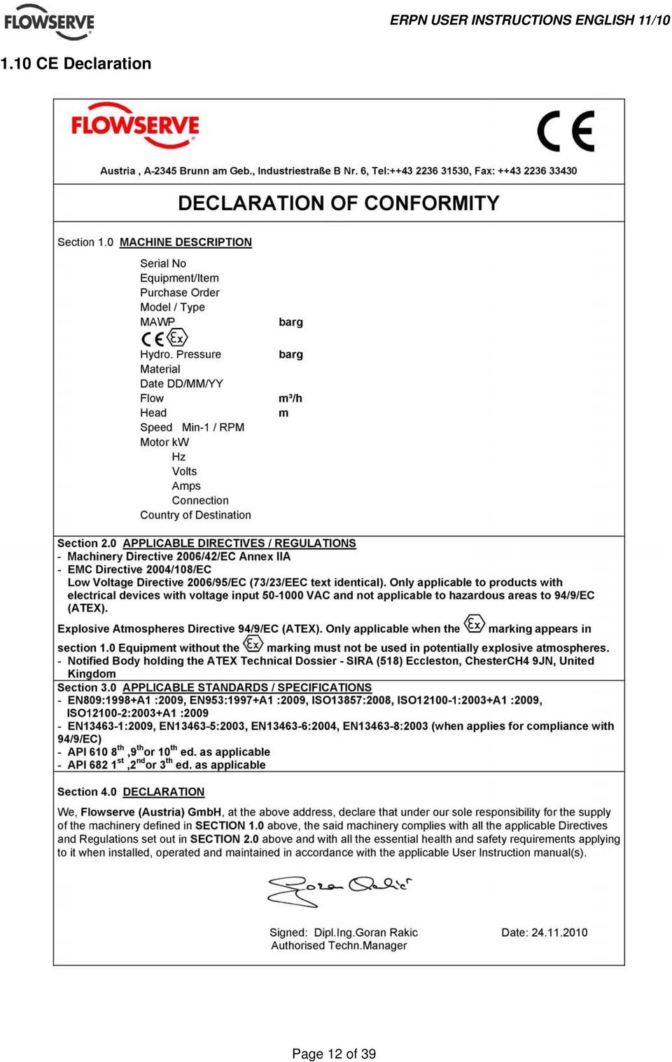
12 1.10 CE Declaration Page 12 of 39
13 2.0 TRANSPORT AND STORAGE 2.1 Consignment receipt and unpacking Immediately after receipt of the equipment it must be checked against the delivery/ shipping documents for its completeness and that there has been no damage in transportation. Any shortage and or damage must be reported immediately to Flowserve and received in writing within one month of receipt of the equipment. Latter claims cannot be accepted. Check any create/boxes/wrappings for any accessories or spare parts, which may be packed separately with the equipment or attached to side walls of the box or equipment. Each product has a unique serial number. Check that this number corresponds with that advised and always quote this number in correspondence as well as when ordering spare parts or further accessories. Bare pumps shall be lifted as shown below. 2.2 Handling Boxes, crates, pallets or cartons may be unloaded using fork lift vehicles or slings dependent on their size and construction. 2.3 Lifting Four lifting lugs are provided on the baseplate to lift the complete unit. Take care by applying slings or ropes about auxiliary piping and seal systems. A crane must be used for all pump sets in excess of 25kg (55lb). Fully trained personnel must carry out lifting, in accordance with local regulations. The driver and pump weights are recorded on their respective nameplates. 2.4 Storage If the unit will not be put immediately into service, it should be stored in a dry room. To avoid any damage during the storage period, the influence of any low or high frequency vibration must be totally inhibited. If the pump is delivered sealed in a plastic-wrapper, it is of max. importance to avoid any damage of that wrapper, because this will protect the pump against humidity. Therefore it must be checked if this wrapper Page 13 of 39

14 has become cracked and if so, the wrapper must be renewed Long period storage If the pump is delivered in a plastic bag, the preservations stands up for one year. If the storage period exceeds this time, the preservation must be checked and renewed. Also the air tight plastic bag must be changed. Moreover we recommend to order a Flowserve Service Engineer for checking the pump before the first start up. 2.5 Recycling and end of product life At the end of the service life of the product or its parts, the relevant materials and parts should be recycled or disposed of using an environmentally acceptable method and local regulations. If the product contains substances, which are harmful to the environment, these should be removed and disposed of in accordance with current regulations. This also includes the liquids and or gases in the "seal system" or other utilities. Make sure that hazardous substances are disposed of safety and that the correct personal protective equipment is used. The safety specifications must be in accordance with the current regulations at all times. 3.0 DESCRIPTION 3.1 Configuration The model ERPN belongs to Flowserves family of API 610 end suction pumps. The pump line is based on a modular system, thus providing maximum design and operating flexibility. The pump is available with several impeller designs. closed impeller with front and back wear rings. Above a certain size the axial thrust is balanced by balancing holes. semi open impeller with back vanes for abrasive fluids free flow (recessed) impeller for fluids containing fibre All three impeller versions can be combined with an inducer for low NPSHA applications. Also a heat jacketed version exists for crystallizing fluids, e.g. Urea. For high suction pressure applications the balance holes are seized individually to ensure a trouble-free operation. The sense of rotation of the pump is clockwise (CW), looking from the coupling to the shaft end of the pump. 3.2 Nomenclature Example: ERPN X-Ind. 150 Discharge nozzle in mm 200 max. impeller size in mm Ind Inducer X: S high suction pressure O semi open impeller F free flow impeller 3.3 Design of major parts Bearing housing Made of carbon steel. It is flanged to the pump casing and provides enough space for mechanical seals according to API Pump casing The pump casing is of volute type. For larger sizes double volute design is used to minimize radial forces. Back pull out design for easy maintenance, so the casing remains on its foundation in case of repair Hydraulics Closed impeller This is the standard version. Both, the impeller and pump casing have renewable front and back wear rings. Above a certain impeller size, the axial thrust is balanced by balancing holes Free flow impeller The impeller has straight radial vanes and is mounted recessed in the pump casing. The axial thrust is balanced by back vanes Semi open impeller The pump casing is equipped with a renewable wear plate.the axial thrust is balanced by back vanes Inducer All different impellers can be optionally equipped with an inducer for low NPSHA applications Semi open impeller low flow The pump casing is equipped with a diffuser insert with an integrated wear plate.the axial thrust is balanced by back vanes Heat jacketed version For cristallizing fluids, e.g. liquid sulpher, a urea solution heat jacketed version is available. Page 14 of 39

15 Dependent on the pumped fluid the pump maybe fully (casing cover, etc.) or partially head jacketed (just the seal chamber) Procedure of Preheating the pump before Start-up Before priming the pump preheat it for at least one hour to avoid any distortion. Refer to General Arrangement drawing for required steam pressure and flow rate. Dry steam shall be used to avoid condensation and a condensate lock in the heat jacket. 3.4 Performance and operating limits In the interest of operator safety the unit must not be operated above the nameplate conditions. Such operation could result in unit failure causing injury to operating personnel. Consult instruction book for correct operation and maintenance of the pump and its supporting components. 4.0 INSTALLATION Equipment operated in hazardous locations must comply with the relevant explosion protection regulations, see section 1.6.4, Products used in potentially explosive atmospheres. 4.1 Location The pump should be located to allow room for access, ventilation, maintenance and inspection with ample headroom for lifting and should be as close as practicable to the supply of liquid to be pumped. Refer to the general arrangement drawing for the pump set. or of steel. It must be rigid and heavy enough to absorb normal vibrations and shocks Horizontal alignment of the baseplate Horizontal alignment is done with levelling screws. Use a spirit level for correct horizontal alignment of the baseplate. The max. misalignment is 0.5 mm/m baseplate length Steel foundation When the pump unit is mounted directly on structural steel frame, it shall be well supported by constructural beams. It is recommended to check the natural frequency of the steel frame, because it shall not coincide with the pump speed. The exact horizontal alignment is very important! Ensure that the base plate is leveled horizontally to 0.5 mm/m. To avoid any distortion of put shims under the base plate before bolting it down to the steel frame. Welding of the base plate to the steel frame is not recommended because of possible distortion of the same Concrete foundation A concrete foundation must have an exact horizontal alignment and must be placed on solid ground. First a basic foundation shall be built with square shaped holes for embedding the foundation bolts. After putting the base plate into the foundation the proper alignment can be obtained by adjusting it with shims under the base plate. Now insert the foundation bolts and grout the space between the basic foundation and the base plate with grouting cement (refer to illustration) It is very helpful to use a properly made and stable wooden frame around the base plate. So the grouting cement will not flow side. When the grouting is totally set and hardened the foundation bolts shall be tightened in a firm and symmetrical way. 4.2 Part Assemblies The pumps are delivered completely mounted and prealigned with the motor. Also the shaft seal is in the correct position. Final alignment after complete installation is necessary. If drivers and/or seal systems are delivered separately, follow the assembly procedure in section Foundation The foundation shall be located on a place that allows a minimum of pipe work and that is easily accessible for inspection during operation. According to the environment the foundation may consist of concrete Page 15 of 39

16 For more details refer to the manufacturer s instruction manual of coupling. a) b) 4.4 Initial alignment The adjustment of motor and pump must be checked (if necessary, make a new adjustment) before first start up of the unit. Parallel Angular a) Angular Offset: The median lines of shafts intersect half-way between the ends of the two shafts. b) Parallel Offset: The median lines run parallel. The maximum allowable parallel offset depends on the size of coupling and is indicated in the instruction manual of manufacturer of coupling c) Axially Offset: Another offset is the displacement of one or both of the shafts. A typical example is thermal expansion. How the alignment of the coupling should be done you can see on the sketches and explanations below! c) Ensure pump and driver are isolated electrically and the half couplings are disconnected. Align the motor to the pump, not the pump to the motor. Alignment of the motor is achieved by using the adjustment screws Permissible misalignment limits at working temperature When checking parallel alignment, the total indicator read-out (TIR) shown is twice the value of the actual shaft displacement. The pump is only pre-aligned! Carefully check or read just alignment before start of the unit. Take out the spacer of the coupling and check the alignment of shafts end of pump and driver. The maximum allowable angular offset should not exceed 0,05 degree, this means the alignment of the shaft ends should be 0,1 mm (0.004 in.). The maximum parallel offset should not exceed 0,05 mm (0.002 in) and the axially offset can be ± 1 mm (0.04 in.). a) b) c) a) Fix the dial gauge on the driven shaft and check the concentricity by turning of both hubs; correct it if necessary. b) Fix the dial gauge on one of the hubs and check the uniformity of the distance by turning of both hubs.; correct it if necessary. c) Fix the dial gauge on the driving shaft and check the concentricity by turning of both hubs; correct it if necessary. If the pump is handling hot liquid, the alignment must be rechecked in warm condition of the unit. The alignment of the unit shall be checked again after 200 service hours. Page 16 of 39
 Axially Offset: Another offset is the displacement of")
17 4.5 Piping General Protective covers are fitted to the pipe connections to prevent foreign particles entering during transportation and installation. Ensure that these covers are removed from the pump before connecting any pipes. Maximum forces and moments allowed on the pump flanges vary with the pump size and type. To minimize these forces and moments which may cause misalignment, hot bearings, worn couplings, vibration and a possible failure of the pump, the following points shall be strictly followed: a) Prevent excessive external pipe load. b) Do not connect piping by applying external force (use of wrenches, crane,...). Piping shall be aligned without residual stress. c) Do not mount expansion joints so that their force, due to internal pressure, acts on the pump flange. Fitting an isolator and non-return valves can allow easier maintenance. Never throttle pump on suction side and never place a valve directly on the pump inlet nozzle. A non-return valve shall be located in the discharge pipework to protect the pump from excessive back pressure and hence reverse rotation when the unit is stopped. Piping and fittings shall be flushed before use. To avoid damages of the pump install a Y-strainer or a strainer of 40 mesh. Piping for corrosive liquids shall be arranged to allow pump flushing before removal of a unit Vent All ERPN pump casings provides self venting through top discharge nozzle arrangement. A small bore at the top of the seal chamber ensures venting of the same Drain This connection is used for total drainage of the pump casing. A flanged drain is standard and can be optionally equipped with various kinds of valves. Refer to GA drawing for details of the drain connection. By pumping toxic or explosive media, provide the necessary security actions, e.g. flushing with nitrogen. 4.6 Electrical connections Electrical connections must be made by a qualified Electrician in accordance with the relevant local national and international regulations. It is important to be aware of the EUROPEAN DIRECTIVE on hazardous areas where compliance with IEC is an additional requirement for making electrical connections. It is important to be aware of the EUROPEAN DIRECTIVE on electromagnetic compatibility when wiring up and installing equipment on site. Attention must be paid to ensure that the techniques used during wiring/installation do not increase electromagnetic emissions or decrease the electromagnetic immunity of the equipment, wiring or any connected devices. If in any doubt contact Flowserve for advice. The motor must be wired up in accordance with the motor manufacturer's instructions (normally supplied within the terminal box) including any temperature, earth leakage, current and other protective devices as appropriate. The identification nameplate should be checked to ensure the power supply is appropriate. A device to provide emergency stopping must be fitted. If not supplied pre-wired to the pump unit the controller/starter electrical details will also be supplied within the controller/starter. For electrical details on pump sets with controllers see the separate wiring diagram. See section 5.4, Direction of rotation before connecting the motor to the electrical supply. 4.7 Final shaft alignment check After connecting piping to the pump, rotate the shaft several times by hand to ensure there is no seizure and all parts are free. Recheck the coupling alignment, as previously described, to ensure no pipe strain. If pipe strain exists, correct piping. Page 17 of 39
 Do not connect piping by applying external force (use of wrenches, crane,...). Piping shall be aligned without residual stress.")
18 5.0 COMMISSIONING START-UP, OPERATION AND SHUTDOWN These operations must be carried out by fully qualified personnel. 5.1 Precommissioning procedure a) The bearing housing must be filled with the indicated oil. Check also the oil level. b) The pump must be completely filled with liquid to avoid running dry and to guarantee a correct performance of the pump. c) During filling the pump shall reach the specified temperature, so pumps for hot liquids (T > 100 C (212 F)) shall be warmed up by preflushing. d) Check the sense of rotation of the pump (Coupling spacer dismantled). Sense of rotation is clockwise viewed to the drive end of the pump. e) The shaft seal must be in correct axial position. Mounting plates of mechanical seal must be locked at the seal gland in open position. Drive-collar of the mechanical seal sleeve must be tightened. f) Check the readiness of all auxiliary systems (seal sys., lubrication sys.,...) for start up. g) All pipe work, including the internal and the auxiliary pipe work, must be connected correctly and must be absolutely tight. Check the tightness of all connections of the auxiliary pipe work. The suction valve must be open, the discharge valve shall be closed. h) Turn the pump by hand, if required with the help of a lever, to check the free rotation of the rotor. The rotor must turn uniformly and noiselessly. Some resistance may be felt due to friction in bearings and seals. i) Check the readiness of the driver for start up. Refer to the manual of the driver (preheating for explosion proof E-motor). 5.2 Pump Lubricants Lubrication The bearing housing shall be filled with proper lubricating oil prior to start up. If the pump will be started after a longer storage period, the bearing housing should be first flushed and cleaned with gasoline. It is not necessary to remove the preservation oil as this will mix up thoroughly with the lubrication oil. Lubrication is provided by the pumping effect of the rotating ball bearings. Maintaining the correct oil level (middle of the oil sight glass) ensures that the lower ball bearing is covered with oil. As option a 1 / 2 NPT connection for a purge oil mist lubrication is provided (refer to General Arrangement Drawing). For recommended lubricating oils refer to the lubrication table Purge oil mist lubrication For preventing, that dirt or humidity get into the bearing housing, this pump is equipped with a 1 / 2 NPT connection for air or nitrogen supply. Also at standstill the air or nitrogen supply shall be maintained. The pressure shall be between 0.01 bar (0.14 psi) and 0.02 bar (0.29 psi), otherwise you have to consider an oil leakage and as a result a bearing damage. The provided flow rate shall be 0,1 SCFM. The supplied air or nitrogen shall be clean and dry Oil change After first start up, the oil shall be changed after 200 service hours. Every further oil change shall take place after about 2000 service hours or at least every 6 month. To change the oil use the following procedure: a) Remove the reservoir (for some type of oilers you must loose a fixing screw or lock nut, refer to section Oil level). b) Open the oil drain on the bearing housing to remove the oil. c) Close the oil drain and fill in Oil through the oiler until the oil level reaches the bottom of the sight glass. d) Fill the reservoir and put it quickly to the body of the oiler. Observe the level in the reservoir. It will decrease until the required oil level is reached (middle of the sight glass). Ensure that enough oil remains in the reservoir. e) If necessary, the oil level can be adjusted by referring to section Oil level Oil level The correct oil level is in the middle of the oil sight glass and shall be checked when pump is not in operation. Periodically check if the lubricating oil is mixed with any condensed water. Careful opening of the oil drain during a stop of the pump will show any water. Use a spirit level to check the horizontal alignment of the bearing housing. A too high oil level will result in higher bearing temperatures and therefore poorer lubrication Adjusting of ADAMS Constant Level Oiler This design of Constant Oiler prevents the flooding of the bearing by means of the positive setting in the Oiler, thus maintaining the correct oil level at all times. When these Oilers are used on Ball or Roller bearings, the installation is the same as described Page 18 of 39
 During filling the pump shall reach the specified temperature, so pumps for hot liquids (T > 100 C (212 F)) shall be warmed up by preflushing.")
19 below, excepting that the oil level in the bearing should never cover more than maximum above inside diameter of the outer race at its lowest point. If the pump is fitted with a Constant Level Oiler type "ADAMS", no adjustment of the oil level is possible Adjusting of TRICO Constant Level Oiler If the pump is fitted with a Constant Level Oiler type TRICO, the correct oil level has to be checked after fitting the pump! Dimension a is the distance from the centerline of the pump to the minimum oil level (marks at the bearing housing). housing). After that check the dimension from the oiler rim to the adjusting screw and compare it with the dimension x, if required turn the adjusting nut with tolerances of plus 0 mm and minus 2 mm (see figure), and fix it. b) Additionally you can check the correct oiler adjustment by an oil sight glass (minimum oil level is the middle of the oil sight glass). Size of Bearing Frame radial roller bearing [3012] thrust ball bearing [3013] Dimension a mm (in) 1 NU BECB (J),(M) 28 (1.1) 2 NU BECB (J),(M) 40 (1.58) 3 NU BECB (J),(M) 49 (1.93) 4 NU BECB (J),(M) 57 (2.24) 5 NU BECB (J),(M) 65 (2.56) 6 NU BECB (J),(M) 72 (2.83) Refer to nameplate or part list, to reading the correct frame size Adjusting of DENCO Constant Level Oiler If the pump is fitted with a Constant Level Oiler type DENCO, the correct oil level has to be checked after fitting the pump! Dimension a is the distance from the centerline of the pump to the minimum oil level (marks at the bearing housing). 1 Trico-Oiler 2 fixing screw 3 levelling screw 4 oil sight glass 5 oil drain 6 counternut a) To check quickly the correct oiler adjustment, measure the dimension x from the oiler-rim to the minimum oil level (lower mark at the bearing 1 Denco Oiler 2 lock nut 3 adjusting sleeve 4 oil sight glass 5 oil drain 6 distance sleeve Page 19 of 39
.")
20 a) The oil level may be fine tuned by turning the adjusting sleeve (3) and finally locked into position by tightening the lock nut (2). To replenish, the reservoir and adaptor (1) may be removed by sliding it out of the body, removing the adaptor and fill the reservoir. Fully reinserting the adaptor / reservoir into the body ensures the previously adjusted oil level is maintained. The oiler is equipped with an overflow tube to avoid a rise of the oil level. This is necessary to maintain a constant level in an oil bath lubrication system, where an oil mist is used as primary lubrication. The oiler is preadjusted with the distance sleeve [6], therefore no adjustment is required anymore. b) Additionally you can check the correct oiler adjustment by an oil sight glass (correct oil level is the middle of the oil sight glass). Size of Bearing Frame radial roller bearing [3012] thrust ball bearing [3013] Dimension a mm (in) 1 NU BECB (J),(M) 28 (1.1) 2 NU BECB (J),(M) 40 (1.58) 3 NU BECB (J),(M) 49 (1.93) 4 NU BECB (J),(M) 57 (2.24) 5 NU BECB (J),(M) 65 (2.56) 6 NU BECB (J),(M) 72 (2.84) Refer to nameplate or part list, to reading the correct frame size Oil quality Oil used for lubrication should only be of high quality. The viscosity of the oil at working temperature must be at least 10 cst. The pouring point of the oil must be in accordance with the lowest expected temperature of the bearing housing during a stop of the pump. For recommended lubricating oils refer to the lubrication table. Having selected the corresponding oil quality the actual oil temperature at the bearing housing must be checked after two service hours of the pump. Considering this measured oil temperature the actual viscosity must be determined by using the data sheet of the oil, to verify the minimum required viscosity of 10 cst. Do not forget, the oil temperature in the bearing itself is about 10 C (50 F) higher than the oil temperature at the bearing housing. On the following table the oil viscosity is given at 40 C (104 F). Determining the correct lubricating oil one must take into consideration that all bearings will have higher temperatures during the first 20 service hours. In constant operation the bearing temperature will decrease about 10 C (50 F). The oil temperature shall be lower than 85 C (185 F) after this runningin time. The bearing outer race temperature should not exceed 95 C (204 F). If the temperature is higher, the reason may be a wrong oil quality, wrong oil level or overload of the pump because of excessive wear. If the humidity at the site is high, the roller bearings become easily rusty during stand still periods. To avoid that, we recommend to mix the lubricating oil with a corrosion inhibitor contact your lubrication oil supplier for proper additives inhibitors Oil quantity Frame I Bearing size is shown on the name plate of the pump, and with this the correct thrust bearing frame can be selected according to the following table. Bearing housing [3200] with Oiler [3855] without Oiler [3855] Oil quantity 0,42 l (14.2 Fl.oz.) 0,3 l (10.1 Fl.oz.) Oil quantity Frame II Bearing size is shown on the name plate of the pump, and with this the correct thrust bearing frame can be selected according to the following table. Bearing housing [3200] with Oiler [3855] without Oiler [3855] Oil quantity 0,62 l (21 Fl.oz.) 0,5 l (16.9 Fl.oz.) Oil quantity Frame III Bearing size is shown on the name plate of the pump, and with this the correct thrust bearing frame can be selected according to the following table. Bearing housing [3200] with Oiler [3855] without Oiler [3855] Oil quantity 0,82 l (27.7 Fl.oz.) 0,7 l (23.7 Fl.oz.) Oil quantity Frame IV Bearing size is shown on the name plate of the pump, and with this the correct thrust bearing frame can be selected according to the following table. Bearing housing [3200] with Oiler [3855] without Oiler [3855] Oil quantity 1,42 l (48 Fl.oz.) 1,3 l (43.9 Fl.oz.) Page 20 of 39

USER INSTRUCTIONS. Installation Operation Maintenance. ERPN-M centrifugal pumps. Horizontal, End Suction Magnetic Driven
 USER INSTRUCTIONS ERPN-M centrifugal pumps Horizontal, End Suction Magnetic Driven Installation Operation Maintenance PCN=71569270, 71569272, 71569273 02-08 (E) Original Instructions Type: ERPN-M Size:
IMPORTANT SAFETY NOTICE
 IMPORTANT SAFETY NOTICE To: Our Valued Customers User safety is a major focus in the design of our products. Following the precautions outlined in this manual will minimize your risk of injury. ITT Goulds
Industrial Process Pump Safety Manual IMPORTANT SAFETY NOTICE
 Industrial Process Pump Safety Manual IMPORTANT SAFETY NOTICE To: Our Valued Customers User safety is a major focus in the design of our products. Following the precautions outlined in this manual will
PBX Series Quick Fit Connector Bimetallic Steam Traps
 6262100/6 IM-P626-01 ST Issue 6 PBX Series Quick Fit Connector Bimetallic Steam Traps Installation and Maintenance Instructions 1. Safety information 2. General product information 3. Installation 4. Commissioning
Oil and Coolant Circulating Heating System. Model - OCSM
 Oil and Coolant Circulating Heating System Model - OCSM Installation & Operation Manual 216280-000 REV 2 Identifying Your System The HOTSTART heating system is designed to heat fluids for use in marine
USER INSTRUCTIONS. Installation Operation Maintenance. Vertical Turbine Pumps Wet Pit (VTP) Double Casing (VPC)
 Double Casing (VPC)") USER INSTRUCTIONS Vertical Turbine Pumps Wet Pit (VTP) Double Casing (VPC) E, S and A series VTPs in wet pit and suction barrel designs ranging in sizes from 50 mm (6 in.) to 1300 mm (52 in.) with a single
USER INSTRUCTIONS Vertical Turbine Pumps Wet Pit (VTP) Double Casing (VPC) E, S and A series VTPs in wet pit and suction barrel designs ranging in sizes from 50 mm (6 in.) to 1300 mm (52 in.) with a single
USER INSTRUCTIONS. Installation Operation Maintenance. Twin Screw Rotary Pumps. External and Internal Bearing Design
 USER INSTRUCTIONS Twin Screw Rotary Pumps External and Internal Bearing Design Installation Operation Maintenance PCN=71569243/71569244 07/10 (E) Original Instructions These instructions must be read prior
BPW32 DN15, DN20 and DN25 Balanced Pressure Wafer Steam Trap
 1263050/6 IM-P126-07 ST Issue 6 BPW32 DN15, DN20 and DN25 Balanced Pressure Wafer Steam Trap Installation and Maintenance Instructions 1. Safety information 2. General product information 3. Installation
OPERATING AND MAINTENANCE INSTRUCTIONS PUMP TYPE 215.10
 OPERATING AND MAINTENANCE INSTRUCTIONS PUMP TYPE 215.10 To Pump model Pump number Our order Your order Order date Reference Item number Destination Plant Before storing, installation, operation or maintenance
Installation and safety instructions for AC/DC built-in devices
 The device type and date of manufacture (week/year) can be found on the device rating plate. In the event of any queries about the device, please quote all the details given on the rating plate. For further
Maintenance and Service Instruction
 Screw pumps E4 Maintenance and Service Instruction E4 1 IMO AB This instruction is valid for all E4 pump models shown on page 2 Contents Page List of components 2 Exploded view/ordering code 3 Service
GT Horizontal Split Casing Pumps
 GT Horizontal Split Casing Pumps 302-054 Operations and Maintenance Manual SUPERSEDES: New EFFECTIVE: March 1, 2009 Plant ID No. 001-3930 SAFETY REQUIREMENTS These operating instructions must be complied
Owner s Manual. Models: 2S5P & 3S5P OPERATION AND MAINTENANCE OF SELF-PRIMING CENTRIFUGAL TRASH PUMPS PEDESTAL DRIVE
 Owner s Manual Models: 2S5P & 3S5P OPERATION AND MAINTENANCE OF SELF-PRIMING CENTRIFUGAL TRASH PUMPS PEDESTAL DRIVE WARNING!! Installation & Operating Instructions Self-Priming Centrifugal Pump DO NOT
FIXED DISPLACEMENT HYDRAULIC VANE PUMPS BQ SERIES
 BQ FIXED DISPLACEMENT HYDRAULIC VANE PUMPS BQ SERIES Versatility, power, compactness and low running costs are the main characteristics of B&C vane pumps. All the components subject to wear are contained
3620 W 11th Streetб Houston, TX 77008 Telephone: 713-635-6291 Email: sales@kellogg-american.com Website: www.kellogg-american.com
 Unpackaging & Handling Be sure to carefully inspect the unit before accepting the shipment. If any damage has occurred document it with the trucking company immediately. Contact your Kellogg Distributor
FIXED DISPLACEMENT HYDRAULIC VANE PUMPS BQ SERIES
 BQ FIXED DISPLACEMENT HYDRAULIC VANE PUMPS BQ SERIES Versatility, power, compactness and low running costs are the main characteristics of B&C vane pumps. All the components subject to wear are contained
FIXED DISPLACEMENT HYDRAULIC VANE PUMPS BQ SERIES
 BQ FIXED DISPLACEMENT HYDRAULIC VANE PUMPS BQ SERIES Versatility, power, compactness and low running costs are the main characteristics of B&C vane pumps. All the components subject to wear are contained
USER INSTRUCTIONS. Installation Operation Maintenance. LN, LNE, LNH, LNV, LNEV, LNC and LNEC centrifugal pumps
 USER INSTRUCTIONS LN, LNE, LNH, LNV, LNEV, LNC and LNEC centrifugal pumps Single stage, double suction, horizontally split, volute type centrifugal pumps Installation Operation Maintenance PCN=71576423
ALIGNMENT. Pump and Driver Alignment
 ALIGNMENT Pump and Driver Alignment Alignment Subject: Pump and Driver Alignment In the pump business alignment means that the centerline of the pump is aligned with the centerline of the driver. Although
Hydraulic control unit series 0086-372-01
 Technical Product Information No. 1290 EN Hydraulic control unit series 0086-372-01 Contents Page About this Technical Product Information (TPI) 2 The ORTLINGHAUS numbering system 2 About the product 3
INSTALLATION AND MAINTENANCE INSTRUCTIONS FOR THREE PHASE INDUCTION MOTORS
 INSTALLATION AND MAINTENANCE INSTRUCTIONS FOR THREE PHASE INDUCTION MOTORS Frames 143T - 449TZ 5100 North IH 35 Round Rock, Texas 78681 Phone: 800-451-8798 512-255-4141 Fax: 512-244-5512 RECEIVING 1. Check
Pump Division. D-814, D-824 Centrifugal Pumps USER INSTRUCTIONS: INSTALLATION, OPERATION, MAINTENANCE PCN=75373613 05/04
 Pump Division D-814, D-824 Centrifugal Pumps USER INSTRUCTIONS: INSTALLATION, OPERATION, MAINTENANCE PCN=75373613 05/04 CONTENTS 1. INTRODUCTION AND SAFETY...3 1.1 General...3 1.2 CE marking and approvals...3
Lenntech. 1000 psi End port pressure vessels 2.5. User s Guide to: Phoenix Vessel Technology Limited. Model number: 1503
 1 User s Guide to: Phoenix Vessel Technology Limited 1000 psi End port pressure vessels 2.5. Model number: 1503 Lenntech info@lenntech.com Tel. +31-152-610-900 www.lenntech.com Fax. +31-152-616-289 Phoenix
SunMaxx Solar Filling Station Operating Instructions
 SunMaxx Solar Filling Operating Instructions Content 1. Declaration of conformity... 2 2. Introduction... 2 3. Transportation and unpacking... 4 4. Mounting and commissioning... 5 5. End of operation...
300 SERIES 331, 332, 333, 344, 356 AND 367 MODELS
 Section: MOYNO 500 PUMPS Page: 1 of 8 Date: March 1, 1998 SERVICE MANUAL MOYNO 500 PUMPS 300 SERIES 331, 332, 333, 344, 356 AND 367 MODELS Mechanical Seal Models Packing Gland Models MODELS DESIGN FEATURES
EX-TECH SAS CP/PB 150 EXPLOSIONPROOF MANUAL CALL POINT/ PUSH BOTTON TECHNICAL MANUAL
 PRODUCT NAME: CP/PB -150- EXPLOSION-PROOF-MANUAL CALL POINT/ PUSH BOTTON DOC NO.: EX-TECH SAS-12-CP-PB150-TM REV01 EXPLOSION-PROOF MANUAL CALL POINT/ PUSH BOTTON II 2GD EPL Gb, Db Ex d IIC T6, IP66 Ex
This instruction is valid for all ACD pump models shown on page 2
 Screw pumps ACD Maintenance and Service Instruction This instruction is valid for all ACD pump models shown on page 2 Contents Page List of components 2 Exploded view/ordering code 3 Service intervals
Float and Thermostatic Traps Series H, C and X
 Hoffman Specialty Installation & Maintenance Instructions HS-(E) and Thermostatic Traps Series H, C and X Series C & NPT Series C NPT Series X NPT Series C NPT Series H Ratings Maximum Max. Operating NPT
2" & 3" Poly Wet Seal Pump Instruction Manual
 Always place the pump as close to the liquid to be pumped as possible. Keep the suction line short and with few bends. Keep the pump and engine on a level foundation. A poor foundation and a heavy suction
CENTRIFUGAL PUMP OVERVIEW Presented by Matt Prosoli Of Pumps Plus Inc.
 CENTRIFUGAL PUMP OVERVIEW Presented by Matt Prosoli Of Pumps Plus Inc. 1 Centrifugal Pump- Definition Centrifugal Pump can be defined as a mechanical device used to transfer liquid of various types. As
Trouble Shooting. Pump
 Trouble Shooting Pump Trouble Possible Cause Remedy Oil leaking in the area of water pump crankshaft Worn crankshaft seal, bad bearing, grooved shaft, or failure of retainer o-ring. Excessive play on crankshaft
BOWIE PUMPS OPERATION - MAINTENANCE
 BOWIE PUMPS OPERATION - MAINTENANCE PUMPING PRINCIPLE: The meshing owieeof the gears cause a slight depression, with the resulting enmeshing of the gears causing a vacuum drawing the fluid being pumped
Ergo-Pro Single Line Solar Station Installation and Operating Instructions
 Rp 3/4 Ergo-Pro Single Line Solar Station Installation and Operating Instructions Item No Pump type 677.21.70 WILO ST 15/6 13 2 4 11 Technical Specifications Max. operating pressure: 6 bar Max. operating
DiscPlus DX195 and DX225 Air Disc Brakes
 Revised 11-04 Technical Bulletin Revised 1 Technical 11-04 Bulletin DiscPlus DX195 and DX225 Air Disc Brakes Inspection, Installation and Diagnostics Air Disc Brake Inspection Intervals and Procedures
IEC Three Phase AC Motors (Aluminum Frame) Installation & Operating Manual
 Installation & Operating Manual") IEC Three Phase AC Motors (Aluminum Frame) Installation & Operating Manual 7/09 MN301 Table of Contents Section 1 General Information.................................................. 1-1 Overview........................................................
IEC Three Phase AC Motors (Aluminum Frame) Installation & Operating Manual 7/09 MN301 Table of Contents Section 1 General Information.................................................. 1-1 Overview........................................................
Vision Engravers and Routers PRE-Installation Guide. 2015 Vision Engraving & Routing Systems
 Vision Engravers and Routers PRE-Installation Guide Revised: 8/19/2015 Vision Engravers and Routers PRE-Installation Guide All rights reserved. No parts of this work may be reproduced in any form or by
Vertical selfpriming Side-Channel Pumps Type WPV
 Vertical selfpriming Side-Channel Pumps Type WPV FIELD OF APPLICATION The side-channel pumps are selfpriming and operate more economically (better efficiency) than normal centrifugal pumps when handling
SERIES ASM NEOPRENE/EPMD FLANGED SINGLE SPHERE CONNECTOR CONNECTORS. Pressures to 225 PSIG (15.51 barg) Temperatures to 230ºF (110ºC)
 Temperatures to 230ºF (110ºC)") APPLICATIONS Process Industry Weak Acids Alkalies Compressed Air Pulp & Paper MODELS ASM - Flanged Connection OPTIONS Control Rods Oil & Gas Water & Waste Pump suction & discharge Sea water Chemical lines
APPLICATIONS Process Industry Weak Acids Alkalies Compressed Air Pulp & Paper MODELS ASM - Flanged Connection OPTIONS Control Rods Oil & Gas Water & Waste Pump suction & discharge Sea water Chemical lines
PET-10 INSTRUCTION MANUAL PRESSURE TANK
 INSTRUCTION MANUAL PRESSURE TANK PET-10 This manual contains IMPORTANT WARNINGS and INSTRUCTIONS. Equipment in this manual is exclusively for painting purposes. Do not use for other purposes. The operator
Instructions Manual. Electromagnetic sensor Series FLOMID FX. instrumentation for fluids. R-MI-FlomidFX Rev.: 0 English version
 instrumentation for fluids Electromagnetic sensor Series FLOMID FX Instructions Manual! Conforms with the Pressure Equipment Directive 97/23/EC. 0830 This equipment is considered as being a pressure accessory
VERTICAL TURBINE AND PROPELLER PUMPS
 VERTICAL TURBINE AND PROPELLER PUMPS INTRODUCTION Vertical Turbine and Propeller Pumps Model 7000 Series Turbine Pump Model 800 Series Axial Flow Propeller Pump Model 800 Series Mixed Flow Propeller Pump
FJ2. 2 Ton Trolley Floor Jack Assembly & Operating Instructions
 FJ2 2 Ton Trolley Floor Jack Assembly & Operating Instructions READ ALL INSTRUCTIONS AND WARNINGS BEFORE USING THIS PRODUCT. This manual provides important information on proper operation & maintenance.
Wilo SP Series Submersible Sump Pumps ECS. ECS19-15.25 ECS22-15.33 ECS24-15.50 Installation and operating instructions
 Wilo SP Series Submersible Sump Pumps ECS ECS19-15.25 ECS22-15.33 ECS24-15.50 Installation and operating instructions PREINSTALLATION CHECK Inspect this pump before it is used. Occasionally, pumps can
Field Application Note
 Field Application Note Reverse Dial Indicator Alignment RDIA Mis-alignment can be the most usual cause for unacceptable operation and high vibration levels. New facilities or new equipment installations
3097 en - 2013.06 / e. This manual is to be given to the end user POULIBLOC 2000-3000. Shaft mount reducer. Installation
 097 en - 0.06 / e 8 en This manual is to be given to the end user POULIBLOC 000-000 Installation LEOY-SOME ISTALLATIO POULIBLOC 000-000 097 en - 0.06 / e This document complements the general instructions
INSTALLATION, OPERATION & MAINTENANCE MANUAL
 INSTALLATION, OPERATION & MAINTENANCE MANUAL Flanged Disk Check Valve with Strainer Ref. GENEBRE: 2450 2451 2452 1 INSTRUCTIONS FOR INSTALLATION, OPERATION & MAINTENANCE MANUAL 1. Spare parts... 3 1.1
MEMBRANE VACUUM MINI PUMPS
 MEMBRANE VACUUM MINI PUMPS The mini pumps described in this page are membrane-type. They can be used both as vacuum pumps and compressors. In the latter version they can supply compressed air 100% oil-free
Pump Skid Fabrication for Magnetic Coupling. Rick Soltis Chief Mechanic City of Bedford
 Pump Skid Fabrication for Magnetic Coupling Rick Soltis Chief Mechanic City of Bedford Contents Magnetic Couplings What They Are, How They Work, Where They re Used Fabrication and Manufacturing of Pump
HYDRAULIC LIFT TABLE CART 2200-LB.
 HYDRAULIC LIFT TABLE CART 2200-LB. OWNER S MANUAL WARNING: Read carefully and understand all MACHINE ADJUSTMENT AND OPERATION INSTRUCTIONS before operating. Failure to follow the safety rules and other
AC Electric Motors best practice
 If you want to learn more about best practice machinery maintenance, or world class mechanical equipment maintenance and installation practices, follow the link to our Online Store and see the Training
PALLET JACK - 2.5 TON
 PALLET JACK - 2.5 TON 39939 SET UP AND OPERATING INSTRUCTIONS Visit our website at: http://www.harborfreight.com Read this material before using this product. Failure to do so can result in serious injury.
Operataing Manual. Single stage radial Fan. Model MKV/TKV
 01.2011 Operataing Manual Single stage radial Fan Model MKV/TKV REITZ-SCHWEIZ VENTILATOR AG Zentweg 11 CH-3006 Bern Telefon +41 (0) 31 / 938 85-85 Telefax +41 (0) 31 / 938 85-86 Internet: www.reitz-schweiz.ch
OHV / OHVL Type OH3 Vertical Inline Pumps ISO 13709 (API 610)
") OHV / OHVL Type OH3 Vertical Inline Pumps ISO 13709 (API 610) The Heart of Your Process OHV / OHVL Type OH3 Vertical Inline Pumps ISO 13709 (API 610) OHV OHVL OHV/OHVL Sales Presentation slide
OHV / OHVL Type OH3 Vertical Inline Pumps ISO 13709 (API 610) The Heart of Your Process OHV / OHVL Type OH3 Vertical Inline Pumps ISO 13709 (API 610) OHV OHVL OHV/OHVL Sales Presentation slide
SEISMIC VELOCITY TRANSDUCER T1-40
 SEISMIC VELOCITY TRANSDUCER T1-40 Measurement of Omnidirectional Absolute Vibrations Certified according to ATEX 94/9/CE directive OPERATION Transducer T1-40 serves for seismic measurement of the absolute
Mechanical Installation
 Page -1-1. INTRODUCTION AND PURPOSE 1.1. This specification covers the installation, testing and precommissioning of mechanical equipment. Work is to be performed in conjunction with the manufacturer s
Packaged Terminal Air Conditioner Wall Sleeve Installation
 Installation & Maintenance Data IM 1196 Group: PTAC Part Number: 910141799 Date: October 2013 Packaged Terminal Air Conditioner Installation x 42" PGAN with Top-Mounted Hydronic Heat Note: Installation
Eurovacuum EV Series. Single Stage Oil Sealed Rotary Vane Pump
 Eurovacuum EV Series Single Stage Oil Sealed Rotary Vane Pump Eurovacuum EV Series Single Stage Oil Sealed Rotary Vane Pumps Eurovacuum Company is offering its various products to meet industrial vacuum
System Saver 318 Air Compressor for Mack E-Tech and ASET Engines
 Maintenance Manual 31 System Saver 318 Air Compressor for Mack E-Tech and ASET Engines Revised 08-05 NON-THROUGH DRIVE THROUGH DRIVE Service Notes About This Manual This manual provides service and repair
MT MOTORI ELETTRICI. Installation, operation, maintenance and safety manual for motors used in hazardous areas 1-II-2G 21-II-2D
 MT MOTORI ELETTRICI Installation, operation, maintenance and safety manual for motors used in hazardous areas 1-II-2G 21-II-2D TABLE OF CONTENTS 1. Introduction 2. Scope of application 3. Installation
SJT / SJM / SJP Large Vertical Pumps
 SJT / SJM / SJP Large Vertical Pumps The Heart of Your Process SJT, SJM, SJP Large Vertical Pumps Product Overview SJT Turbine Ns 1800 < 5000 nq 35 < 110 SJM Mixed Flow Ns 5800 < 8300 nq 113 < 161 SJP
Pump and Valve Components and Maintenance
 Pump and Valve Components and Maintenance Outline: 1. Split case and End Suction pumps, industry in the 21 st century, cost of ownership, and performance tips 2. Split case Pumps features, maintenance,
OPERATION & MAINTENANCE MANUAL. for VERTICAL INLINE PUMPS
 OPERATION & MAINTENANCE MANUAL for VERTICAL INLINE PUMPS PATTERSON PUMP COMPANY A SUBSIDIARY OF THE GORMAN-RUPP COMPANY PO Box 790 9201 Ayersville Road Toccoa, Georgia 30577 Telephone: 706-886-2101 SAFETY
Model 362A AURORA. 340A/360A Series SINGLE STAGE END SUCTION PUMPS. www.aurorapump.com
 Model 62A MODEL 41A MODEL 44A AURORA 40A/60A Series SINGLE STAGE END PUMPS www.aurorapump.com SINGLE STAGE END PUMPS AURORA 40A/60A Series Single Stage End Suction Pumps Capacities to 4500 G.P.M. (1022
TYPE APPROVAL CERTIFICATION SCHEME MASS PRODUCED DIESEL ENGINES
 1. Introduction TYPE APPROVAL CERTIFICATION SCHEME MASS PRODUCED DIESEL ENGINES 1.1 This scheme details the tests and inspection of diesel engines manufactured by mass production system for use in marine
Single-Phase AC Synchronous Generator
 ST Series Single-Phase AC Synchronous Generator Instructions for Operation and Maintenance English to English translation by R.G. Keen, May 2004. ST Series of Single-Phase AC Synchronous Generators Description
CRN5-5 A-FGJ-G-E-HQQE 3x230/400 50HZ
 GRUNDFOS DATA BOOKLET CRN5-5 A-FGJ-G-E-HQQE 3x23/4 5HZ Grundfos Pump 96517184 Thank you for your interest in our products Please contact us for more information, or visit our website http://www.lenntech.com/grundfos/crn5/96517184/crn-5-5-a-fgj-g-e-hqqe.html
Operating Manual. Los Angeles Abrasion Machine HM-70A & HM-70AF
 Operating Manual Los Angeles Abrasion Machine HM-70A & HM-70AF Rev: 07/19/2012 PHONE: 800-444-1508 P.O. Box 200, Lewis Center, Ohio 43035-0200 FAX: 800-255-5314 740-548-7298 E-mail: customerservice@gilsonco.com
CEILING CASSETTE FAN COIL UNIT
 CEILING CASSETTE FAN COIL UNIT Operation and Installation Manual MHCFC4W-04, 08, 12, 16 Four way ceiling cassette fan coil unit Please read this manual before using the fan coil unit. Installation and
Operating instructions
 ebm-papst Mulfingen GmbH & Co. KG Bachmühle D-74673 Mulfingen Phone +49 (0) 7938 81-0 Fax +49 (0) 7938 81-110 info1@de.ebmpapst.com www.ebmpapst.com CONTENTS 1. SAFETY REGULATIONS AND S 1.1 Levels of hazard
Drive shaft, servicing
 Volkswagen Passat B6 - Drive shaft, servicing Стр. 1 из 41 40-7 Drive shaft, servicing Drive shafts, overview I - Assembly overview: Drive axle with CV joint VL100 40-7, Drive axle with CV joint VL100,
1/3 HP Submersible Sump Pump with Vertical Float Switch
 1/3 HP Submersible Sump with Vertical Float Switch Item 68476 Specifications Float Switch Operation Height 7.1 IN. ON / 2.8 IN. OFF Electrical Requirements 120V~ / 60Hz / 7.6A Power Length Maximum Capacity
PEDAL CAR - GO CART ASSEMBLY & OPERATING INSTRUCTIONS
 PEDAL CAR - GO CART 42822 ASSEMBLY & OPERATING INSTRUCTIONS 3491 Mission Oaks Blvd., Camarillo, CA 93011 Visit our Web site at: http://www.harborfreight.com Copyright 2000 by Harbor Freight Tools. All
Operating Instructions
 Operating Instructions Cable Glands Ex d and Ex e with Compound > Contents 1 Contents 1 Contents...2 2 General Information...2 3 General Safety Information...3 4 Designated Use...4 5 Technical Data...4
Wafer Check Valve ASAHI AV VALVES. Contents. User s Manual. (1) Be sure to read the following description of our product warranty 1
 Be sure to read the following description of our product warranty 1") Serial No. H-V066-E-2 Wafer Check Valve User s Manual Contents (1) Be sure to read the following description of our product warranty 1 (2) General operating instructions 2 (3) General instructions for
Serial No. H-V066-E-2 Wafer Check Valve User s Manual Contents (1) Be sure to read the following description of our product warranty 1 (2) General operating instructions 2 (3) General instructions for
National- Spencer Inc.
 9-27-2010 National- Spencer Inc. 19.2V HEAVY DUTY GREASE GUN PRODUCT SPECIFICATION Charger Input Power 110 VAC Battery Output Power 19.2V Battery Capacity 1500 MAH Battery Pack Charge Time 1 Hour Maximum
X8 X13A X14 - AC Gearless
 This manual is to be given to the end user X8 X13A X14 - AC Gearless Installation and maintenance THIS MANUAL MUST REMAINS WITH THE MACHINE. THE TABLE (page 4) MUST BE SUPPLEMENTED TO ATTEST GOOD REALIZATION
due to uncertainty. This, in turn, has a direct impact on equipment availability and maintenance costs. Unfortunately, due to misconceptions and
 due to uncertainty. This, in turn, has a direct impact on equipment availability and maintenance costs. Unfortunately, due to misconceptions and pressure from plant operators to get "back on line", it
Instructions for Safe Use
 Instructions for Safe Use (Certification N:o VTT 08 ATEX 029) Thank you for choosing Slam Trans portable transformer for your job site. Purpose of this manual is to provide you all the necessary safety
Troubleshooting for: Premier Supplier of Pumps & Parts
 Premier Supplier of Pumps & Parts Troubleshooting for: 115 Hilton Street West Easton, PA 18042 USA (800)854-0539 fax: (800)926-9508 http://www.processflo.com 4 Operation Pay attention to possible faults.
Table of Contents. Overview 1. Pump Disassembly 2. Control Disassembly / Reassembly 7. Pump Reassembly 13. Adjustment Procedures DR Control 19
 Table of Contents Overview 1 Pump Disassembly 2 Control Disassembly / Reassembly 7 Pump Reassembly 13 Adjustment Procedures DR Control 19 Adjustment Procedures DRG Control 20 Adjustment Procedures DFR
Transformer oil cooler ALFA A02
 A02 Transformer oil cooler ALFA Transformer oil cooler ALFA The transformer oil cooler ALFA is used to cool power transformers by means of forced air and oil flow. The oil in the cooler is circulated using
IWAKI Magnetic Drive Pump MDM Series (ANSI) Instruction Manual
 Instruction Manual") IWAKI Magnetic Drive Pump MDM Series (ANSI) Instruction Manual Read this manual before use of product Thank you for selecting IWAKI Magnetic Drive Pump MDM Series. This instruction manual, which is divided
IWAKI Magnetic Drive Pump MDM Series (ANSI) Instruction Manual Read this manual before use of product Thank you for selecting IWAKI Magnetic Drive Pump MDM Series. This instruction manual, which is divided
HYDRAULIC TABLE CART 500-LB.
 HYDRAULIC TABLE CART 500-LB. OWNER S MANUAL WARNING: Read carefully and understand all MACHINE ADJUSTMENT AND OPERATION INSTRUCTIONS before operating. Failure to follow the safety rules and other basic
PUMPS TYPE OF PUMP PRESSURE/FLOW RATING CHARACTERISTICS. Centrifugal Low Pressure/High Flow Flow changes when
 PUMPS Pumps provide the means for moving water through the system at usable working pressures. The operation and maintenance of these pumps are some of the most important duties for many water utility
Standard offering (pumps)
") MDM PUMPS LTD Spring Lane Malvern, Worcs. England. WR14 1BP This outlines what we typically supply. Tel: +44 (0)1684 892678 Fax: +44 (0)1684 892841 E-mail: Website: Standard offering (pumps) info@mdmpumps.co.uk
MDM PUMPS LTD Spring Lane Malvern, Worcs. England. WR14 1BP This outlines what we typically supply. Tel: +44 (0)1684 892678 Fax: +44 (0)1684 892841 E-mail: Website: Standard offering (pumps) info@mdmpumps.co.uk
Hydraulics Trouble Shooting Guide. TS-Guide_R.doc
 Hydraulics Trouble Shooting Guide TS-Guide_R.doc Table of Contents Condensed Table... 1 Valves... 3 Cylinders... 3 Boosters... 4 Fluid Motors... 5 Vane Pumps... 6 Radial Piston Pumps... 9 Hydraulic Systems...
GENERAL INSTALLATION, OPERATION, MAINTENANCE AND TROUBLESHOOTING MANUAL FOR THREE SCREW AND CIG SERIES PUMPS
 GENERAL INSTALLATION, OPERATION, MAINTENANCE AND TROUBLESHOOTING MANUAL FOR THREE SCREW AND CIG SERIES PUMPS WARNING This manual, and the pump specific Product Service Manual, should be read thoroughly
Pallet Jack. OWNER S MANUAL Model MH1230. Important Safety Instructions Assembly Instructions Parts and Hardware Identification
 OWNER S MANUAL Model MH1230 Important Safety Instructions Assembly Instructions Parts and Hardware Identification Pallet Jack CAUTION: Read, understand and follow ALL instructions before using this product
15GAL STEEL OIL DRAIN WITH 110V PUMP
 15GAL STEEL OIL DRAIN WITH 110V PUMP OWNER S MANUAL WARNING: Read carefully and understand all ASSEMBLY AND OPERATION INSTRUCTIONS before operating. Failure to follow the safety rules and other basic safety
Static Electricity. A Health and Safety Guideline for Your Workplace. What Are Some Sources of Static Electricity? What is Static Electricity?
 A Health and Safety Guideline for Your Workplace What is static electricity? What causes it? How is it hazardous? And, most importantly, how can it be controlled? All of these questions will be answered
INSTALLATION & OPERATING INSTRUCTIONS
 INSTALLATION & OPERATING INSTRUCTIONS WARNING RISK OF ELECTRIC SHOCK. CONNECT ONLY TO A CIRCUIT PROTECTED BY A GROUND-FAULT CIRCUIT-INTERRUPTER. THE UNIT SHOULD BE INSTALLED BY A QUALIFIED SERVICE REPRESENTATIVE.
Rexroth Hydraulic Pump A10VO Series User Manual
 Rexroth Hydraulic Pump A10VO Series User Manual Rexroth Hydraulic pump A10VO Series User Manual Revised 5/1/2009 Page 1 of 12 Functional Purpose This pump is preferred over a fixed displacement (gear)
OPERATION & MAINTENANCE MANUAL. for 5 X 3 MAC - 5 X 4 MAC DOUBLE SUCTION SPLIT CASE PUMPS
 OPERATION & MAINTENANCE MANUAL for 5 X 3 MAC - 5 X 4 MAC DOUBLE SUCTION SPLIT CASE PUMPS PATTERSON PUMP COMPANY A SUBSIDIARY OF THE GORMAN-RUPP COMPANY PO Box 790 9201 Ayersville Road Toccoa, Georgia 30577
James M. Pleasants Company
 James M. Pleasants Company SUBMITTAL DATA GAINESVILLE MECHANICAL DECEMBER 20, 2013 PROJECT: GSU: J-183 HUMANITIES LAW BLDG. QUOTE NO:12116 ENGINEER: STEVENS & WILKINSON GASKETED PLATE HEAT EXCHANGER Tag:
Mechanical shaft seal types and sealing systems
 Chapter 2 Mechanical shaft seal types and sealing systems 1. Mechanical shaft seal types 2. Sealing systems 3. Selecting a mechanical shaft seal Mechanical shaft seal types and sealing systems 1. Mechanical
ITE. Indirect calorifier ITE - 400/500/600/750/1000. Installation, User and Service Manual. Innovation has a name.
 ITE Indirect calorifier ITE - 400/500/600/750/1000 0310 117 Installation, User and Service Manual Innovation has a name. Read this manual carefully Warning Read this manual carefully before starting the
IMPORTANT SAFETY RULES TO FOLLOW
 WARNING FLOOR & CARPET CLEANER Any piece of equipment can be dangerous if not operated properly. YOU are responsible for the safe operation of this equipment. The operator must carefully read and follow
ORC TURBOGENERATOR TYPE CHP - Organic Rankine Cycle Turbogenerator fed by thermal oil, for the combined production of electric energy and heat -
 Doc. : 08C00031_e Date : 10.02.2009 Page : 1 / 9 ORC TURBOGENERATOR TYPE CHP - Organic Rankine Cycle Turbogenerator fed by thermal oil, for the combined production of electric - (Preliminary) Doc. : 08C00031_e
Mini Pallet Jack OWNER S MANUAL
 Mini Pallet Jack OWNER S MANUAL WARNING: Read carefully and understand all ASSEMBLY AND OPERATION INSTRUCTIONS before operating. Failure to follow the safety rules and other basic safety precautions may
Rotary Pump Startups. A pre-startup guide that will help keep gremlins away from your system. By James R. Brennan
 Rotary Pump Startups A pre-startup guide that will help keep gremlins away from your system. By James R. Brennan Many pump startups are the culmination of months if not years of work designing the process,