Vision Engravers and Routers PRE-Installation Guide Vision Engraving & Routing Systems
|
|
|
- Brittney Henderson
- 8 years ago
- Views:
Transcription
1 Vision Engravers and Routers PRE-Installation Guide Revised: 8/19/2015

2 Vision Engravers and Routers PRE-Installation Guide All rights reserved. No parts of this work may be reproduced in any form or by any means - graphic, electronic, or mechanical, including photocopying, recording, taping, or information storage and retrieval systems - without the written permission of the publisher. Products that are referred to in this document may be either trademarks and/or registered trademarks of the respective owners. The publisher and the author make no claim to these trademarks. While every precaution has been taken in the preparation of this document, the publisher and the author assume no responsibility for errors or omissions, or for damages resulting from the use of information contained in this document or from the use of programs and source code that may accompany it. In no event shall the publisher and the author be liable for any loss of profit or any other commercial damage caused or alleged to have been caused directly or indirectly by this document. Revised: 8/19/2015

3 Contents 3 Table of Contents Part I Introduction and Computer Requirements 4 Part II General Electrical and Facility Requirements by Model 5 Part III Express and VE Express... Layout Diagram 7 2 VE Layout Diagram 7 Part IV Phoenix Phoenix Layout Diagram 9 Part V 16 Series and 24 Series Engravers and Engraver Layout Diagram and Engraver Layout Diagram 12 Part VI 16 Series and 25 Series Routers 13 1 High Frequency... Router Head 13 2 Engraving... Head R... Router Layout Diagram and Router Layout Diagrams 19 Part VII MAX and MAX PRO 22 1 MAX and... MAX PRO Layout Diagram 23 Part VIII VR48 Router 24 1 Requirements Wiring... Connections 28 3 Vacuum... Pump Connections - Vacuum Table Models Only 32 4 VR48... Router Layout Diagrams 33 3

4 4 1 Vision Engravers and Routers PRE-Installation Guide Introduction and Computer Requirements This guide contains information to prepare the new owner of a Vision Engraver or Router for the proper installation of their machine. It is the customer's responsibility to read through this guide and make sure the work area, electrical and computer requirements are met prior to the arrival of a representative from Vision for the scheduled installation/machine orientation date (Training NOT included with Vision Express machines). If for any reason, there are questions about these requirements, please call your Vision representative as soon as possible. IMPORTANT Once your training day is scheduled, if for any reason you have to cancel training or change the dates, you may be subject to fees associated with your change request. However, if the trainer arrives at your facility on the day of training and you have to cancel or reschedule training at that time, a fee of $750 will be required before Vision will send the trainer back to your facility in addition to fees associated with your change request. No exceptions. IT IS HIGHLY RECOMMENDED THAT THE COMPUTER USED TO OPERATE THE VISION ENGRAVER OR ROUTER BE CONNECTED TO THE INTERNET. THIS ALLOWS THE USER TO ALLOW VISION'S TECHNICAL SUPPORT TO ACCESS THE MACHINE AND TROUBLESHOOT IF NECESSARY. Minimum System Requirements CPU: Hard Drive: RAM: Operating System: Ports: Suggested System Requirements CPU: Hard Drive: RAM: Operating System: Ports Dual Core (2.0GHz or higher) 500 GB 1GB + OS Requirements Windows Bit & 64 Bit Windows 8 & Bit & 64 Bit Windows 7-32 Bit & 64 Bit Windows XP SP3-32 Bit (64 Bit not supported) USB port for security dongle Local or network Ethernet port to connect machine Core i3 (or faster) 1 TB (or more) 4GB + OS Requirements Windows Bit & 64 Bit Windows 8 & Bit & 64 Bit Windows 7-32 Bit & 64 Bit USB port for security dongle Local or network Ethernet port to connect machine Please skip the the appropriate section for details regarding your specific machine.
.")
5 Introduction and Computer Requirements 2 5 General Electrical and Facility Requirements by Model Machine Model Requirements Express, VE-810, 1612, 1624 Engraver, 2424, 2448, MAX and MAX Pro One 110 VAC 15 Amp or One 220 VAC 10 Amp Single Phase 1624R, 2525 and 2550 Router - T-Slot Table With High Frequency Router Head One 110 VAC 15 Amp or One 220 VAC 10 Amp Single Phase (for Vision controller) AND One 220 VAC 30 Amp Single Phase (for 3 HP router motor) With Engraving Head One 110 VAC 15 Amp or One 220 VAC 10 Amp Single Phase With NSK High Frequency Spindle Two 110 VAC 15 Amp, or Two 220 VAC 10 Amp Single Phase 2550 Router with Vacuum Table With High Frequency Router Head One 110 VAC 15 Amp or One 220 VAC 10 Amp Single Phase (for Vision controller) AND One 220 VAC 30 Amp Single Phase (for 3 HP router motor) AND One 220 VAC 30 Amp 3 Phase (for vacuum table pump) With Engraving Head One 110 VAC 15 Amp or One 220 VAC 10 Amp Single Phase (for Vision controller) AND One 220 VAC 30 Amp 3 Phase (for vacuum table pump) With NSK High Frequency Spindle Two 110 VAC 15 Amp, or Two 220 VAC 10 Amp Single Phase AND One 220 VAC 30 Amp 3 Phase (for vacuum table pump) VR48 Router - T-Slot Table One 220 VAC 50 Amp Single Phase (for Vision machine) AND One 110 VAC 25 Amp or One 220 VAC 15 Amp Single Phase (for extraction unit) VR48 Router - Vacuum Table One 220 VAC 50 Amp Single Phase (for Vision machine) AND One 110 VAC 25 Amp or One 220 VAC 20 Amp Single Phase (for extraction unit) AND One 220 VAC 40 Amp 3 Phase (for vacuum table pump) Optional Equipment Engraving Vacuum Chip Removal System Router Chip Extraction System Optional Equipment Requiring Compressed Air Supply UNIST Misting System NSK High Frequency Spindle One 110 VAC 15 Amp One 110 VAC 25 Amp or One 220 VAC 20 Amp Single Phase Clean Dry Compressed Air Supply PSI Clean Dry Compressed Air Supply 1 40 PSI NOTE: In addition to the above requirements, a 110 VAC standard outlet is required for the computer.
 AND One 220 VAC 30 Amp Single Phase")
6 6 3 Vision Engravers and Routers PRE-Installation Guide Express and VE-810 Vision Express and VE-810 Connections On the rear of the Vision Express and VE810, there are three connection ports. The power port, the Ethernet port and the remote on/off port for the optional Vacuum Chip Removal System. Vision Express (rear view) For the Vision Express: Connect the power supply cable to a VAC source, then connect the power supply plug into the port on the back of the machine. Plug the Ethernet cable into the Ethernet port. Vision VE810 (rear view) For the VE810: Connect the power cable to a VAC source, then plug the power cable into the port on the back of the machine. Plug the Ethernet cable into the Ethernet port.

7 Express and VE Express Layout Diagram 3.2 VE-810 Layout Diagram 7

8 8 4 Vision Engravers and Routers PRE-Installation Guide Phoenix 1212 Phoenix 1212 Engraver/Series 4 Controller Connections There is only one connection port on the Phoenix It is a 25 pin Table Cable port on the left side of the machine. All other connections on the machine's controller are listed below. 1. The engraver's Pendant is connected to the Pendant cable port. 2. The Ethernet Cable from your computer, hub or network is connected to the Ethernet port. 3. The Table Cable connects from 25 pin connector on the engraver to the Table port. 4. The Power Cable connects a VAC electrical source to the controller and powers the controller, table and spindle. Note: If your machine is equipped with the optional Vacuum Chip Removal System, a remote On/Off cable is connected to the controller to automatically turn the vacuum pump on and off when the job is being run.

9 Phoenix Phoenix 1212 Layout Diagram 9

10 10 5 Vision Engravers and Routers PRE-Installation Guide 16 Series and 24 Series Engravers 16 and 24 Series Engraver/Series 4 Controller Connections 1. The engraver's Pendant is connected to the Pendant cable port. 2. The Ethernet Cable from your computer, hub or network is connected to the Ethernet port. 3. The Auxiliary Table Cable is used on the 24 Series engraver ONLY. 4. The Table Cable connects from 25 pin connector on the engraver to the Table port. 5. The Spindle Cable connects to the Spindle port. 6. The Power Cable connects a VAC electrical source to the controller and powers the controller, table and spindle. 7. If your machine is equipped with the optional Vacuum Chip Removal System, a remote On/Off cable is connected to the controller to automatically turn the vacuum pump on and off when the job is being run. 8. *If your machine is equipped with the optional NSK High Frequency Spindle, an second 25 pin connector will be included with your controller. The NSK Spindle is controlled by the NSK Spindle Cable connected to this port. NOTE - the Spindle Cable to the standard engraving motor will not be used in this configuration. Series 4 Pendant and Controller

11 16 Series and 24 Series Engravers and 1624 Engraver Layout Diagram 11

12 Vision Engravers and Routers PRE-Installation Guide 2424 and 2448 Engraver Layout Diagram

13 16 Series and 24 Series Engravers 6 16 Series and 25 Series Routers 6.1 High Frequency Router Head 13 High Frequency Router Head Wiring Connections 1. The controller Pendant is connected to the Pendant port on the controller. 2. The Ethernet Cable from your computer, hub or network is connected to the Ethernet port on the controller 3. The Auxiliary Table Cable is used on the 25 Series machines ONLY. It connects the Serial Table Connector on the machine to the Aux Table port on the controller. 4. The Table Cable connects from 25 Pin Table Connector on the machine to the Table Port on the controller 5. The machine's Spindle Cable connects to the Spindle port on the controller. 6. The Power Cable connects a VAC electrical source to the controller and powers the controller and table. 7. The MOD/BUS Cable from the Inverter connects to the MOD/BUS port on the controller and controls the High Frequency Router Motor. Series 4 Controller (rear view) Router Head Connections Pendant

14 14 Vision Engravers and Routers PRE-Installation Guide Wiring Connections for Inverter (used with High Frequency Router Head only) NOTE: The Auxiliary Power Cable is pre-wired on all 16 and 25 Series Routers. Remove Inverter Cover and feed the Auxiliary Power Cable through hole in bottom of Inverter. Connect the three black wires labeled, T1, T2 and T3, to their respective connection points. Connect the Green (Ground) wire to the connection point shown. Connect the Main Power Cable to a 220VAC source and connect the MOD/BUS Cable to the machine controller's MOD/BUS port.

15 16 Series and 25 Series Routers 15 Carriage Wiring Connections The Motor Plug connects to the Spindle Port on the back of the Carriage. Carriage (rear view) Mounting the Inverter on the 25 Series Table Stand The Inverter is mounted on the top-left corner of the machine's stand. There are two flanges mounted on the rear of the inverter. These flanges are placed in the inside of the stand's legs. Screws are included with the inverter to secure the inverter to the stand. Instructions for assembly of the stand are included with the stand, which is packed underneath the machine in its shipping crate.

16 Vision Engravers and Routers PRE-Installation Guide Engraving Head Engraving Head Wiring Connections 1. The controller Pendant is connected to the Pendant port on the controller. 2. The Ethernet Cable from your computer, hub or network is connected to the Ethernet port on the controller 3. The Auxiliary Table Cable is used on the 25 Series machines ONLY. It connects the Serial Cable Port on the machine to the Aux Table port on the controller. 4. The Table Cable connects from 25 Pin Table Connector on the machine to the Table Port on the controller 5. The machine's Spindle Cable connects to the Spindle port on the controller. 6. The Power Cable connects a VAC electrical source to the controller and powers the controller and table. Series 4 Controller (rear view) Engraving Head Connections Pendant NOTE: The Auxiliary Power Cable which is pre-wired on all 16 and 25 Series Routers is NOT used with the Engraving Head. If your router was not equipped with the High Frequency Router Head or the Porter Cable Router Head, this cable can remain disconnected at all times.

17 16 Series and 25 Series Routers Carriage Wiring Connections The Motor Plug connects to the Spindle Port on the back of the Carriage. Carriage - rear view 17

18 Vision Engravers and Routers PRE-Installation Guide 1624R Router Layout Diagram

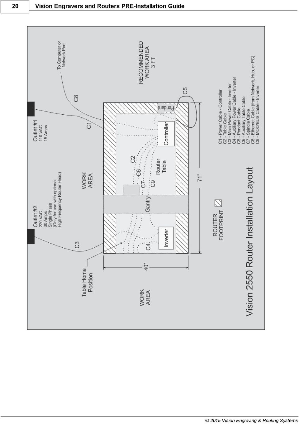
19 16 Series and 25 Series Routers and 2550 Router Layout Diagrams 19

20 20 Vision Engravers and Routers PRE-Installation Guide
21 16 Series and 25 Series Routers 21
22 22 7 Vision Engravers and Routers PRE-Installation Guide MAX and MAX PRO Max and Max Pro Connections The Vision Max and Max Pro machines have an integrated controller inside the base of the machine. The machines need to have the following cables connected to the controller. 1. The engraver's Pendant is connected to the Pendant cable port. 2. The Ethernet Cable from your computer, hub or network is connected to the Ethernet port. 3. The Auxiliary Table Cable is connected to the Aux Table port and powers the machine's rotary axis. 4. The Table Cable connects from 25 pin connector on the engraver to the Table port. 5. The Power Cable connects a VAC electrical source to the controller and powers the controller, table and spindle. 6. The Pump Cable (Max Pro only) connects to the Pump/Mist port and powers the machine's water pump for glass engraving. 7. Main Power switch (for reference only) 8. If you machine was equipped with the optional Vacuum Chip Removal System, the Vacuum Cable from the vacuum pump will connect to the Vacuum port. Series 4 Pendant and Integrated Controller Connections
23 MAX and MAX PRO MAX and MAX PRO Layout Diagram * This dimension is added to allow for clearance on the rear of the machine for cables and for air flow to the cooling fan. Vision MAX Vision MAX PRO
24 24 8 Vision Engravers and Routers PRE-Installation Guide VR48 Router Unloading the Crate - IMPORTANT INFORMATION Please follow these guidelines when unloading the crated machine from the freight truck. The VR48 is shipped in a large framed crate with all accessories loaded under the machine. The crate presents a significant tip hazard when using lower capacity fork lifts. When unloading the crate from the freight truck, it is highly recommended that an experienced fork lift operator or rigging company be utilized. The forklift must have a minimum capacity of 6,000 lbs and 6' or longer forks. Keep crate close to ground level when transporting on fork lift. Unload machine from crate before transporting machine into facility.
25 VR48 Router Requirements Electrical Connections 1. A qualified and licensed electrician must be used to complete all wiring and grounding of the machine according to all state, local, and national electrical codes. 2. Make sure all Junction Boxes and Outlets are mounted according to all state, local and national electrical codes. 3. Junction Box #1 (50 Amp, 220 VAC, Single Phase) will power the router table, spindle, and controls. It is typically mounted on Wall A, approximately 36 to 48 inches above the floor surface. The box should be level with the left edge of the router table. (Refer to Installation Layout Diagrams). 4. Junction Box #2 - for machines equipped with Vacuum Tables ONLY - (40 Amp. 220 VAC, 3 Phase) will power the Vacuum Pump. Mounting should be on Wall A and between 36 inches and 48 inches above the floor surface. If locating the vacuum pump as shown (Refer to Installation Layout Diagram), locate Junction Box #2 no greater than 4 feet from Junction Box #1. 5. Outlet #1 (20 Amp, 220 VAC, Single Phase) should be mounted on Wall A as shown (Refer to Installation Layout Diagram - Section 2.1). This can also be another Junction Box if the Dust Collector is to be direct wired to its electrical source. The dust collector is approximately 2 feet x 3 feet and is on wheels. 6. Outlet #2 (15 Amp, 110 VAC, Single Phase) should have multiple standard three prong sockets for the computer. It is typically located near the bottom left corner of the router table (home position) as shown (Refer to Installation Layout Diagram). 7. Wiring needs to be completed to the junction boxes, outlets, etc. before the scheduled first installation/machine orientation day.
26 26 Vision Engravers and Routers PRE-Installation Guide Locating the Router 1. A doorway of at least 80 inches wide and 80 inches high is required in order for the router to be moved into your facility. 2. Locate machine indoors on a flat surface and on a solid foundation. 3. Temperature must remain between 40 F and 85 F. 4. Do not expose machine to direct sunlight, rain, vibration, dampness, or explosive environments. 5. A forklift is required to remove the crate from the shipping truck and to locate the equipment in the building. The forklift must have a minimum capacity of 6,000 lbs and 6' or longer forks. 6. A pallet jack is required to level the router table. 7. The router table footprint is approximately 6.7 feet x 10.7 feet. A designated work area of at least 5 feet is strongly recommended around all sides of the machine to ensure ease of operation, material handling, cleaning, maintenance and safety. 8. Typically, the vacuum pump is between the router table and Wall A (Refer to Installation Layout Diagram - Section 2.1). Please note the orientation of the pump and motor.
27 VR48 Router 27 Leveling the machine 1. Make sure the machine has been properly located at your work-site. 2. It is not necessary to bolt your machine to the floor in your facility. However, a solid, stable foundation is required to support the machine's weight. 3. There should be a leveling bolt in each of the four machine legs. 4. Place a precision leveling gauge on the machine's table top and adjust the leveling bolts until the machine is level in both the horizontal and vertical directions. Scheduling the Installation 1. Please schedule an electrician for the morning of the first day of installation/machine orientation to connect the router table, vacuum pump motor, and dust collector to the junction boxes and outlets. 2. If an electrician is not available for the installation, please call Vision ASAP in order to reschedule installation/machine orientation. If Vision personnel arrive and the electrical connections are not ready and the electrician is not present, there will be an additional charge $750/day while waiting. WARNING: The first time the Vacuum Pump is turned on, check that the direction of rotation is correct. Turn it on, then off, observing the direction of rotation. It should match the arrow on the pump near the motor. If necessary, swap any two of the three power leads to change the rotation to the opposite direction. Prolonged usage of the vacuum pump when rotating in the incorrect direction can cause permanent damage to the pump.
28 Vision Engravers and Routers PRE-Installation Guide Wiring Connections The Main Power Switch is located on the left side of the VR48. The main power supply is connected to the Main Electrical Box on the left side of the VR48. Remove the cover and make the connections as shown below. Ground is connected to the bare wire and common leads are connected to the two shielded wires. The supply for this connection is Junction Box #1 (220 VAC, Single Phase). Note: The picture below is for illustration purposes only. The power cable should enter the Main Electrical Box through the hole in the left side of the box as shown in the above picture.
29 VR48 Router 29 On the front of the control box for VR48 Router, there are four connection ports; One is an Ethernet port used to connect your computer or network to the on-board Series 4 Controller, the second is for the Pendant, the third is a USB port used to connect a computer to the VR48 when using the DACS Camera System, and the fourth is to connect the Remote Start Switch for the Dust Collector System. Plug the network cable (or the crossover cable) into the Ethernet port on the VR48, then either plug the network cable into your network (or hub), or using the crossover cable, plug into the network port on your computer. Plug the Pendant cable into the Pendant and Pendant Port on the VR48. Connections for the DACS Camera System are detailed in a separate section of this manual. Connect the Dust Collector Remote Start Cable to the Remote Start Port using the supplied cable. NOTE: The crossover cable is colored gray.
30 30 Vision Engravers and Routers PRE-Installation Guide The Dust Collector Remote Start Switch will need to be connected. For ease of operation, a remote start switch and cables can be used to turn on the dust collector automatically when a job is being run. The supply for this connection is from Outlet #1 (220 VAC, Single Phase, 20 Amp).
31 VR48 Router 31 Wiring for this switch is shown below. The input and output wires should be connected as shown. Both input and output ground wires can be connected to the single GND location shown. The switch can be wall mounted at a location convenient for the user. The Remote Start Cable is connected to the Remote Start Port on the front of the machine's control box.
32 Vision Engravers and Routers PRE-Installation Guide Vacuum Pump Connections - Vacuum Table Models Only The Main Vacuum Port for the VR48 is located at the foot of the machine. To connect the vacuum pump to the machine, use the supplied 3" diameter vacuum hose and connect one end to the vacuum pump and the other end to the Main Vacuum Port on the machine. The vacuum pump has been equipped with an electrical connector designed for a 40 amp, 220 VAC, 3 phase power supply. A qualified and licensed electrician must be used to complete all wiring and grounding of the vacuum pump according to all state, local, and national electrical codes.
33 VR48 Router 8.4 VR48 Router Layout Diagrams T-Slot Tables Models 33
34 34 Vision Engravers and Routers PRE-Installation Guide Vacuum Table Models
Control Box Wiring For PRSstandard Tool
 888-680-4466 ShopBotTools.com Control Box Wiring For PRSstandard Tool Copyright 2016 ShopBot Tools, Inc. page 1 Copyright 2016 ShopBot Tools, Inc. page 2 Table of Contents Introduction:...5 Installation:...5
Lava. Precision Solutions. Site Planning and Installation Guide
 Lava Precision Solutions Site Planning and Installation Guide TABLE OF CONTENTS Table of Contents Introduction...........................................................................................
=============================== WARNING
 =============================== WARNING EXPLANATION OF GRAPHICAL SYMBOLS This symbol is intended to alert the user to the presence of unprotected dangerous voltage" within the product's enclosure that
OPL BASIC. Dosing System for Professional Laundry machines. Contents
 OPL BASIC Dosing System for Professional Laundry machines Contents 1 Getting Started. Page 2 2 Installation. Page 4 3 Set Up & Operation. Page 8 4 Maintenance & Accessories. Page 10 5 Troubleshooting Page
ATS Overhead Table Shelf System INSTRUCTION MANUAL
 ATS Overhead Table Shelf System INSTRUCTION MANUAL ATS Overhead Table Shelf System Instruction Manual Warranty Newport Corporation warrants this product to be free of defects in material and workmanship
UPLIFT Height Adjustable Standing Desk (T-Frame) DIRECTIONS FOR ASSEMBLY AND USE - - ALSO - - Watch our assembly video
 DIRECTIONS FOR ASSEMBLY AND USE - - ALSO - - Watch our assembly video") UPLIFT Height Adjustable Standing Desk (T-Frame) DIRECTIONS FOR ASSEMBLY AND USE - - ALSO - - Watch our assembly video http://bit.ly/9ywwh! CAUTION MAKE SURE NO OBSTACLES ARE IN THE DESK S PATH AND ALL
UPLIFT Height Adjustable Standing Desk (T-Frame) DIRECTIONS FOR ASSEMBLY AND USE - - ALSO - - Watch our assembly video http://bit.ly/9ywwh! CAUTION MAKE SURE NO OBSTACLES ARE IN THE DESK S PATH AND ALL
42U/45U 28" Wide Rack Installation & Service Guide
 42U/45U 28" Wide Rack Installation & Service Guide 96-00171-005 Rev B Important Information Information in this document is subject to change without notice and does not represent a commitment on the part
SYSTEM 4C. C R H Electronics Design
 SYSTEM 4C C R H Electronics Design SYSTEM 4C All in one modular 4 axis CNC drive board By C R Harding Specifications Main PCB & Input PCB Available with up to 4 Axis X, Y, Z, A outputs. Independent 25
ARCO Electric Products Installation and Maintenance Manual Low Voltage Automatic Power Factor Correction Capacitor Systems 2013
 ARCO Electric Products Installation and Maintenance Manual Low Voltage Automatic Power Factor Correction Capacitor Systems 2013 READ CAREFULLY These instructions are intended to cover good practices in
PU-USBX. USB over Ethernet Extender OPERATION MANUAL
 PU-USBX USB over Ethernet Extender OPERATION MANUAL Safety Precautions Please read all instructions before attempting to unpack or install or operate this equipment, and before connecting the power supply.
GEU-0822 8-Port Gigabit Switch
 GEU-0822 8-Port Gigabit Switch 1 V1. 1_20150622 1. INTRODUCTION... 3 1.1 Product Briefs... 3 1.2 Product Features... 3 1.3 Hardware Introduction... 4 2. CONNECTING THE SWITCH... 5 2.1 Package Contents...
TrueAlarm Fire Alarm Systems
 TrueAlarm Fire Alarm Systems UL, ULC, CSFM Listed; FM Approved; MEA (NYC) Acceptance* Fire Alarm System Accessories, 4190 Series PC Annunciator with Multi-Client Capability Features Fire alarm control
Installation Instructions
 H5HK Series Installation Instructions 3 Phase Electric Heater Kits 7.5 and 0 TON Package A/C Systems Description Installation of 08/40V and 480V H5HK 3 Phase Heater Kits in 7.5 and 0 TON Packaged Air Conditioners.
Portable Air Conditioner
 Portable Air Conditioner Owner's Manual Model:3 in 1 12,000 Btu/h Series 3 Please read this owner s manual carefully before operation and retain it for future reference. CONTENTS 1. SUMMARY...1 2. PORTABLE
OEM Manual MODEL 2350 ELECTRONIC DUAL CYLINDER SCALE
 OEM Manual MODEL 2350 ELECTRONIC DUAL CYLINDER SCALE Scaletron Industries, Ltd. Bedminster Industrial Park 53 Apple Tree Lane P.O. Box 365 Plumsteadville, PA 18949 USA Toll Free: 1-800-257-5911 (USA &
DCF Optimized Rack System
 Integrated Cabinet Solutions For Business-Critical Continuity DCF Optimized Rack System User Manual IMPORTANT SAFETY GUIDELINES SAVE THESE INSTRUCTIONS This manual contains important instructions that
Static Clean International
 MCS Medical Cleaning Station Unpacking, Set-up & Operation Instructions 1. Uncrating the MCS Unit 1.1. Unscrew the (1) removable crate top and (1) crate panel marked FRONT OPEN THIS SIDE then set them
Draper Low Voltage, Remote Control, Serial and Network Wiring Guide
 Draper Low Voltage, Remote Control, Serial and Network Wiring Guide Copyright 2007 Draper Inc. Form LV-RC-Serial-Network_Wiring07 Print ed in U.S.A. Draper Low Voltage, Remote Control, Serial and Network
16/32 Channel 1U Rack Mount CCTV Power Supply
 16/32 Channel 1U Rack Mount CCTV Power Supply Manual PH-A3224-GUQ Shown 16-Channel 32-Channel PTC PH-A1612-PUQ PH-A3224-PUQ Glass Fuse PH-A1612-GUQ PH-A3224-GUQ Industrial design 12 Amp 3 Amps per channel
USB 2.0 4-Port Extender Kit
 USB 2.0 4-Port Extender Kit 500072 MuxLab Inc. 2014 94-000760-A / SE-000760-A Table of Contents 1. Introduction... 2 2. Features... 2 3. Specifications... 2 4. Package Contents... 3 5. Physical Diagram...
Advantium 2 Plus Alarm
 ADI 9510-B Advantium 2 Plus Alarm INSTALLATION AND OPERATING INSTRUCTIONS Carefully Read These Instructions Before Operating Carefully Read These Controls Corporation of America 1501 Harpers Road Virginia
Uninterruptible Power Supply. 500 kva - 750 kva
 9 315 Uninterruptible Power Supply 500 kva - 750 kva T1 and T3 Installation Addendum 164201244-001 Rev. A ------------------------------------------------------------------------ ------------------------------------------------------------------------
IMMS-CCC. IMMS-CCC Hardwire Central Interface. Installation Instructions
 IMMS-CCC IMMS-CCC Hardwire Central Interface Installation Instructions TABLE OF CONTENTS... Choose a Location... 1 Connections... 2 Operations... 3 Software Configuration... 4 Troubleshooting... 5 Loopback
BUILT-IN DISHWASHER INSTALLATION INSTRUCTIONS
 BUILT-IN DISHWASHER INSTALLATION INSTRUCTIONS PLEASE READ COMPLETE INSTRUCTIONS BEFORE YOU BEGIN LEAVE INSTALLATION INSTRUCTIONS AND USER'S GUIDE WITH OWNER ALL ELECTRIC WIRING AND PLUMBING MUST BE DONE
Specifications for a Precision CNC Vertical Machining Center. Section I. Mechanical Performance Specifications (must meet or exceed)
") Specifications for a Precision CNC Vertical Machining Center Introduction The Naval Research Laboratory Vacuum Electronics Branch requires a high precision computer numerically controlled (CNC) vertical
Specifications for a Precision CNC Vertical Machining Center Introduction The Naval Research Laboratory Vacuum Electronics Branch requires a high precision computer numerically controlled (CNC) vertical
Installation Guide Smart-UPS X Tower/Rack-Mount 2U 2000/2200/3000 VA
 Installation Guide Smart-UPS X Tower/Rack-Mount 2U 2000/2200/3000 VA Important Safety Messages Read the instructions carefully to become familiar with the equipment before trying to install, operate, service
Checking the Package Contents. Installing the Printer Software. Connecting. Unpacking the. the Printer. Printer. Attaching
 Installing the Printer Software Checking the Package Contents Connecting the Printer Unpacking the Printer Installing the Ink Cartridges Plugging in the Printer Attaching the Printer Parts 4032216-00 EUL
2100 POS System. 2100 User Guide
 2100 POS System 2100 User Guide Thank you for selecting UTC RETAIL s innovative Model 2100 Point of Sale solution! This guide is designed to acquaint you with the features and functionality of the 2100
WARNING CANADIAN D.O.C. WARNING
 Each product and program carries a respective written warranty, the only warranty on which the customer can rely. Avery Dennison Corp. reserves the right to make changes in the product, the programs, and
IMPORTANT SAFETY RULES TO FOLLOW
 WARNING FLOOR & CARPET CLEANER Any piece of equipment can be dangerous if not operated properly. YOU are responsible for the safe operation of this equipment. The operator must carefully read and follow
Table of Contents. www.hunterfan.com. What to Expect with. Preparation. Tools Needed. Wiring. Hanging the Fan. Blades. Motor Housing.
 www.hunterfan.com Table of Contents What to Expect with Your Installation 30 inches Hanging the Fan Wiring 8 Maintenance, Operation & Cleaning Light Kit 13??? 14 1 9 Troubleshooting 11 5 Blades Motor Housing
HP UPS R1500 Generation 3
 HP UPS R1500 Generation 3 Installation Instructions Part Number 650952-001 NOTE: The rating label on the device provides the class (A or B) of the equipment. Class B devices have a Federal Communications
RL HW / RL HW+ / RL HGW / RL HV / RL HVPW/RL HVPW-G
 Auto-Levelling Rotary Laser Level RL HW / RL HW+ / RL HGW / RL HV / RL HVPW/RL HVPW-G 77-496 / 77-429 / 77-439 / 77-497 / 77-427/ 77-441 Please read these instructions before operating the product Auto-Levelling
Vertical Display and Storage B1350-2. SKOPE Gen2: Three Door Chiller
 Vertical Display and Storage User Manual MAN1227 Rev. 3.0 March 2008 edition CONTACT ADDRESSES Designed and Manufactured by New Zealand SKOPE INDUSTRIES LIMITED PO Box 1091, Christchurch New Zealand Freephone:
Dehumidifier Users manual. For Models: DH45S DH65S
 Dehumidifier Users manual For Models: DH45S DH65S 950-0062-revD Jan. 9 2007 FORWARD The appearance of the units that you purchase might be slightly different from the ones described in the Manual, but
Owners & Installation Manual for the Sheridan, Mountainair, Pine Valley and Old Forge Ceiling Fan Family
 Owners & Installation Manual for the Sheridan, Mountainair, Pine Valley and Old Forge Ceiling Fan Family Part of the Kiva Lighting Family Custom Lighting and Fans Since 1992 1312 12th St NW Albuquerque,
Z-Truck (Vertical Moving) Z-truck Flag. Y-Truck (Horizontal Moving) FIGURE 1: VIEW OF THE Z-TRUCK. Flexshaft Assembly
 Z-truck Flag. Y-Truck (Horizontal Moving) FIGURE 1: VIEW OF THE Z-TRUCK. Flexshaft Assembly") Replacing the Cover Micro-Switch To remove and replace the Cover Micro-Switch you will need the following tools: #2 Phillips screwdriver (magnetic tip preferred) #1 Phillips screwdriver (magnetic tip preferred)
Replacing the Cover Micro-Switch To remove and replace the Cover Micro-Switch you will need the following tools: #2 Phillips screwdriver (magnetic tip preferred) #1 Phillips screwdriver (magnetic tip preferred)
UB1 AIR CONDITIONING UNIT INSTALLATION INSTRUCTIONS
 UB1 AIR CONDITIONING UNIT INSTALLATION INSTRUCTIONS INSTALLATION INSTRUCTIONS: Carefully read these instructions before installing your new air-conditioner. AUSTRALIAN AUTOMOTIVE AIR AL00500054E 1 Table
User Guide TL-SG1016D 16-Port Gigabit Switch TL-SG1024D 24-Port Gigabit Switch
 User Guide TL-SG1016D 16-Port Gigabit Switch TL-SG1024D 24-Port Gigabit Switch Rev: 1.1.0 7106503251 COPYRIGHT & TRADEMARKS Specifications are subject to change without notice. is a registered trademark
Pre-installation Manual. CONCEPT Processor 305 DW / 405 DW / 505 DW 505 DW XP
 Pre-installation Manual CONCEPT Processor 305 DW / 405 DW / 505 DW 505 DW XP Pre-installation Manual CONCEPT Processor 305 DW / 405 DW / 505 DW / 505 DW XP T11336 Edition AA, April 2013 This book has
36G22, 36G23, 36G24 & 36G52 36J22, 36J23, 36J24 & 36J52 DSI and HSI Single Stage Combination Gas Valve
 Operator: Save these instructions for future use! FAILURE TO READ AND FOLLOW ALL INSTRUCTIONS CAREFULLY BEFORE INSTALLING OR OPERATING THIS CONTROL COULD CAUSE PERSONAL INJURY AND/OR PROPERTY DAMAGE. DESCRIPTION
ECR Shelf System Installation Guide Centralized Rack Mount Call Recording
 Hardware & Installation Guide Algo Communication Products Ltd. Customer Support and Sales Tel: 1.877.884.2546 Fax: 604.437.5726 Email: sales@algosolutions.com support@algosolutions.com www.algosolutions.com
DC Series Digital Conversion Alarm Operator s Manual
 DC Series Digital Conversion Alarm Operator s Manual Ver. 2012 - Rev. 1004 Class 1 Inc. design manufacture installation service world class innovation Call us for your next project. Area Alarm Conversion
Taurus Super-S3 LCM. Dual-Bay RAID Storage Enclosure for two 3.5-inch Serial ATA Hard Drives. User Manual March 31, 2014 v1.2 www.akitio.
 Dual-Bay RAID Storage Enclosure for two 3.5-inch Serial ATA Hard Drives User Manual March 31, 2014 v1.2 www.akitio.com EN Table of Contents Table of Contents 1 Introduction... 1 1.1 Technical Specifications...
Xerox Nuvera Production System and Xerox igen Digital Production Press
 January 2015 702P01084 Xerox Nuvera Production System and Xerox igen Digital Production Press Xerox Nuvera 100/120/144/157 EA Production System Xerox Nuvera 100/120/144 MX Production System Xerox Nuvera
Andersen Electric Window Opener for Andersen Awning and Roof Windows
 W A Electric Window Opener Electric Window Opener for Awning and Roof Windows Congratulations! You have just purchased one of the many fine products. For ease of installation and continued enjoyment of
Oil and Coolant Circulating Heating System. Model - OCSM
 Oil and Coolant Circulating Heating System Model - OCSM Installation & Operation Manual 216280-000 REV 2 Identifying Your System The HOTSTART heating system is designed to heat fluids for use in marine
P3000 Printer Guide. 566372-001 Rev A. January 2006
 P3000 Printer Guide 566372-001 Rev A January 2006 Information resources for the P3000 ID Card Printer Installation Message Help To install one printer to a PC using a USB cable, see the Installation Map,
Convection Ovens. BX Classic. Models BX4 / FG 189C, BX4-6040 / FG 158C, BX10 / FG 180C. Operator's Manual
 Convection Ovens BX Classic Models BX4 / FG 189C, BX4-6040 / FG 158C, BX10 / FG 180C Operator's Manual Belshaw Bros., Inc. 814 44 th Street NW, Suite 103 Auburn, WA 98001 USA Phone: 206-322-5474 Fax: 206-322-5425
NewAir AC-10100E / AC-10100H Portable Air Conditioner Owner s Manual PLEASE READ AND SAVE THESE INSTRUCTIONS
 NewAir AC-10100E / AC-10100H Portable Air Conditioner Owner s Manual PLEASE READ AND SAVE THESE INSTRUCTIONS ELECTRICAL SAFETY This appliance is for indoor use only. Always turn off the unit and unplug
SmartLogger1000. Quick Installation Guide. Issue 05. Date 2013-12-15 HUAWEI TECHNOLOGIES CO., LTD.
 Issue 05 Date 2013-12-15 HUAWEI TECHNOLOGIES CO., LTD. 2013. All rights reserved. No part of this document may be reproduced or transmitted in any form or by any means without prior written consent of
AXIS T81B22 DC 30W Midspan
 INSTALLATION GUIDE AXIS T81B22 DC 30W Midspan ENGLISH About this Document This document includes instructions for installing AXIS T81B22 on your network. Previous experience of networking will be beneficial
1080P. Extender for HDMI over one CAT5. GTV-HDBT-CAT5 User Manual. gefentv.com
 1080P Extender for HDMI over one CAT5 GTV-HDBT-CAT5 User Manual gefentv.com ASKING FOR ASSISTANCE Technical Support: Telephone (818) 772-9100 (800) 545-6900 Fax (818) 772-9120 Technical Support Hours:
Installation Instructions
 Installation Instructions For Use with PXPV230, PXPV265, PXPD230, and PXPD265 models Attention! - Please read these instructions completely before attempting installation. Always unplug the power supply
OASIS-PLUS 120V READ ALL INSTRUCTIONS BEFORE OPERATING READ ALL INSTRUCTIONS BEFORE OPERATING OZONE IS A POWERFUL OXIDIZER AND MUST BE USED WITH CARE
 OASIS-PLUS 120V INFORMATION & OPERATING INSTRUCTIONS READ ALL INSTRUCTIONS BEFORE OPERATING READ ALL INSTRUCTIONS BEFORE OPERATING OZONE IS A POWERFUL OXIDIZER AND MUST BE USED WITH CARE 56041852 WARNING:
Arecont Vision H.264 Color or Day/Night SurroundVideo Series Installation Manual
 0 P a g e H.264 Color or Day/Night SurroundVideo Installation Manual Inside the box: A. Arecont Vision SurroundVideo camera B. Mounting template C. RJ45 female to female coupler D. Hex key E. Security
Cluster Box Units. (CBU s) 3300 Series CBU Door Sizes. Fully Integrated Parcel Lockers CLUSTER BOX UNITS FRONT LOADING. continued on pages 7-11
 3300 Series CBU Door Sizes. Fully Integrated Parcel Lockers CLUSTER BOX UNITS FRONT LOADING. continued on pages 7-11") Cluster Box Units (CBU s) continued on pages 7-11 CLUSTER BOX UNITS FRONT LOADING Made of heavy duty aluminum and stainless steel hardware, Salsbury 3300 series U.S.P.S. approved Cluster Box Units (CBU
Cluster Box Units (CBU s) continued on pages 7-11 CLUSTER BOX UNITS FRONT LOADING Made of heavy duty aluminum and stainless steel hardware, Salsbury 3300 series U.S.P.S. approved Cluster Box Units (CBU
2100 AD 015 0009 Mirror Elevator Ball Nut Replacement Procedure
 2100 AD 015 0009 Mirror Elevator Ball Nut Replacement Procedure Derek Guenther 1/28/2015 Rev. Purpose The purpose of this document is to describe the procedure necessary to replace one of the ball nuts
FOXAIR 60/50 ALL MODELS
 FOXAIR 60/50 ALL MODELS OPERATION AND SERVICE MANUAL UNIT WEIGHT - ALL MODELS APPROX. 300 POUNDS FOXTRONICS, INC. 38 L x 28 W x 24 H Love Field-Dallas TX MADE IN THE USA 3448 West Mockingbird Lane Dallas,
HP SATA/SAS hard drive and Solid State Drive installation
 HP SATA/SAS hard drive and Solid State Drive installation This document describes how to install Serial ATA (SATA) and Serial Attached SCSI (SAS) hard drives or Solid State Drives (SSD) in an internal
ViZion Installation Guide
 ViZion Installation Guide v2.0 1 ViZion Installation Guide Table of Contents Inventory Hardware Setup Understanding Synchronization Cable Begin by taking an inventory of the required equipment DR Unit
http://www.coastalamusements.com
 Nexus is a Registered Trademark of Coastal Amusements. OWNERS MANUAL 1935 Swarthmore Avenue, Lakewood, NJ 08701 (732)-905-6662 FAX (732)-905-6815 http://www.coastalamusements.com GAME DESCRIPTION Nexus
Solar monitoring gateway quick start guide
 Instructional Leaflet I70002E LGATE101-1B LGATE101-1A LGATE101-5B LGATE101-5A Contents Description Page General................................. 2 Information collection sheet............... 2 Quick reference
TruPower-Portable-500W. Solar Starter kit
 TruPower-Portable-500W Solar Starter kit This Solar starter kit is an easy to use solar power supply system that is the complete solution for all your solar power needs. It is a solar generator that converts
DR System Maintenance
 2015 DR System Maintenance Checklist and Guide This document will provide detailed instructions on how to effectively and properly maintain and backup your system for prolonged lifespan and reduced down
GeekDesk Max Instructions for Assembly & Use
 GeekDesk Max Instructions for Assembly & Use Work Sitting OR Standing! With the touch of a button... Elevate Your Work Instructions release 1.5, 2012-08-09 WELCOME! Thank you for purchasing a GeekDesk!
INSTALLATION GUIDE. Card Reader & Controller with KIM Swipe Reader for Solitaire 850 / 950 / 850L Learnlok PK2930
 INSTALLATION GUIDE Card Reader & Controller with KIM Swipe Reader for Solitaire 850 / 950 / 850L Learnlok PK2930 Card Reader and Controller Model 3.5 with KIM Swipe Reader Table of Contents 1. Features..................................
BroadBand PowerShield. User Manual
 BroadBand PowerShield User Manual 990-0375G 12/2006 Chapter 1 General Information The PowerShield provides a power source for broadband telephony and other DC applications. Safety This Safety Guide contains
SERVICE MANUAL 12VDC WALL THERMOSTAT AIR CONDITIONING SYSTEMS ROOFTOP UNITS ONLY
 SERVICE MANUAL 12VDC WALL THERMOSTAT AIR CONDITIONING SYSTEMS ROOFTOP UNITS ONLY! WARNING - SHOCK HAZARD! TO PREVENT THE POSSIBILITY OF SEVERE PERSONAL INJURY, DEATH, OR EQUIPMENT DAMAGE DUE TO ELECTRICAL
Router Table Plans. www.bobsplans.com
 www.bobsplans.com Router Table Plans Increase the capabilities of your router with this weekend project. Features a sliding fence with EZ-Mount clamps. These clamps are simple to make and grip tightly
Single Day Alarm Clock with. Bluetooth and USB Play-through
 Single Day Alarm Clock with Bluetooth and USB Play-through MODEL : BSC 200 READ THIS INSTRUCTION MANUAL BEFORE OPERATING THE APPLIANCE. SAVE THIS MANUAL FOR FUTURE REFERENCE. TABLE OF CONTENTS IMPORTANT
20 GALLON WET DRY VACUUM
 20 Gallon Wet & Dry Vacuum 110" Water Lift Vac Motor 24" Front Mount Squeegee Assembly 50' Cord Special Tip Pour Feature Warranty Contractor Tool Kit Includes: Wet p/u Tool, Dry p/u Tool, Crevice Tool,
Outdoor 33.6W Dual Port Passive Power-over-Ethernet Midspan For External Security Cameras and Wireless Access Points
 Outdoor 33.6W Dual Port Passive Power-over-Ethernet Midspan For External Security Cameras and Wireless Access Points Features SELV Compliant No Detection Passive Injector Gigabit Compatible Full Protection
Daker DK 1, 2, 3 kva. Manuel d installation Installation manual. Part. LE05334AC-07/13-01 GF
 Daker DK 1, 2, 3 kva Manuel d installation Installation manual Part. LE05334AC-07/13-01 GF Daker DK 1, 2, 3 kva Index 1 Introduction 24 2 Conditions of use 24 3 LCD Panel 25 4 Installation 28 5 UPS communicator
Vision Express User Manual. 2015 Vision Engraving & Routing Systems
 Vision Express User Manual Revised: 8/19/2015 Vision Express User Manual All rights reserved. No parts of this work may be reproduced in any form or by any means - graphic, electronic, or mechanical, including
Home Signal Distribution Kit for Satellite TV Plus SIRIUS
 SR-101C SIRIUS/DBS Signal Combiner System SR-2261 Combiner-Outdoor Made in China DBS IN SIRIUS IN SR-101C SIRIUS/DBS Signal Combiner System SR-2251 Splitter-Indoor Made in China DC IN DBS OUT SIRIUS OUT
Installation Manual. Rental Services. Air Handling Units CHS-SVN01A-EN. July 2008
 Installation Manual Rental Services Air Handling Units July 2008 CHS-SVN01A-EN Copyright 2008 Trane All rights reserved This document and the information in it are the property of Trane and may not be
Ingenico. User Guide 5100M. Secure transaction and payment solutions
 User Guide Ingenico 5100M Secure transaction and payment solutions Ingenico 5100 M Contents 1 Presentation... 5 1.1 Overview of Ingenico 5100... 6 1.2 Keyboard details and functionality... 7 2 Use...
No Phone Line II-48 System
 Used in conjunction with an EntraGuard Telephone Entry System, the -48 provides No Phone Line communication and door or gate control through existing building telephone lines without the need to purchase
Preface. Manual Revisions
 Preface D-Link reserves the right to revise this publication and to make changes in the content hereof without obligation to notify any person or organization of such revisions or changes. Manual Revisions
Guardian MAXimus ASSEMBLY MANUAL & USER GUIDE
 Guardian MAXimus ASSEMBLY MANUAL & USER GUIDE TABLE OF CONTENTS 1. INTRODUCTION...1 1.1 MINIMUM SYSTEM REQUIREMENTS 1.1.1 Apple Mac Requirements 1.1.2 PC Requirements 1.1.3 Supported Drives 1.2 PACKAGE
TS2 VRack. User and Installation Manual
 TS2 VRack User and Installation Manual B 4934252 Rev. A October 2007 TS-2 VRack All rights reserved. No parts of this work may be reproduced in any form or by any means - graphic, electronic, or mechanical,
Contents. Section A Networking Basics... 1. 1 Learning the Basics... 3. Section B Wired Ethernet Networking... 17
 Contents Section A Networking Basics...................................... 1 1 Learning the Basics............................................. 3 Selecting a network connection........................................
OWNER S MANUAL DRAINVAC ATOMIK PRINTED APRIL 4-2011
 OWNER S MANUAL th DRAINVAC ATOMIK PRINTED APRIL 4-2011 INTRODUCTION We take this opportunity to express our gratitude and extend our congratulations for your decision to purchase a Drainvac product. A
High PoE Midspans NPD-6001A NPD-9501A. en Installation Manual
 High PoE Midspans NPD-6001A NPD-9501A en Installation Manual High PoE Midspans Table of Contents en 3 Table of contents 1 Safety 4 1.1 About this Manual 4 1.2 Legal Information 4 1.3 Safety Precautions
Out-of-box comparison between Dell and HP blade servers
 Out-of-box comparison between and blade servers TEST REPORT JUNE 2007 Executive summary Inc. () commissioned Principled Technologies (PT) to compare the out-of-box experience of a PowerEdge 1955 Blade
LIEBERT VNSA Installation Sheet
 LIEBERT VNSA Installation Sheet Description The Liebert vnsa network switch is designed for connecting multiple Ethernet-ready devices and comes in various models. The unit may have: A Liebert icom display
SunMaxx Solar Filling Station Operating Instructions
 SunMaxx Solar Filling Operating Instructions Content 1. Declaration of conformity... 2 2. Introduction... 2 3. Transportation and unpacking... 4 4. Mounting and commissioning... 5 5. End of operation...
SMART Board 8070i-SMP and 8070i
 SMART Board 8070i-SMP and 8070i Interactive flat panel Installation guide Product registration If you register your SMART product, we ll notify you of new features and software upgrades. Register online
BATHROOM HEATER. User's Manual. Page 2...A515 Page 9...A716
 BATHROOM HEATER User's Manual Page 2...A515 Page 9...A716 BATHROOM HEATER User's Manual A515 SAVE THESE INSTRUCTIONS AND READ ALL INSTRUCTIONS BEFORE USING THE HEATER. Dear customers, Thank you for selecting
T7560A,B,C Digital Wall Module
 T7560A,B,C Digital Wall Module HONEYWELL EXCEL 5000 OPEN SYSTEM BEFORE INSTALLATION All wiring must comply with local electrical codes and ordinances or as specified on installation wiring diagrams. Digital
Energy Communication Unit (ECU)
") Altenergy Power System Energy Communication Unit (ECU) Installation and User Manual (For ECU-3 V3.8) ALTENERGY POWER SYSTEM INC. All rights reserved TABLE OF CONTENTS 1.0 Introduction... 2 2.0 Installation...
Altenergy Power System Energy Communication Unit (ECU) Installation and User Manual (For ECU-3 V3.8) ALTENERGY POWER SYSTEM INC. All rights reserved TABLE OF CONTENTS 1.0 Introduction... 2 2.0 Installation...
MODEL 2202IQ (1991-MSRP $549.00)
") F O R T H E L O V E O F M U S I C F O R T H E L O V E O F M U S I C MODEL 2202IQ (1991-MSRP $549.00) OWNER'S MANUAL AND INSTALLATION GUIDE INTRODUCTION Congratulations on your decision to purchase a LINEAR
F O R T H E L O V E O F M U S I C F O R T H E L O V E O F M U S I C MODEL 2202IQ (1991-MSRP $549.00) OWNER'S MANUAL AND INSTALLATION GUIDE INTRODUCTION Congratulations on your decision to purchase a LINEAR
Digi-Motor Installation Guide
 Digi-Motor Installation Guide Installation Video...located at marsdelivers.com Digi-Motor Installation Guide Digi-Motor For technical assistance with your Azure Digi-Motor, call the MARS technical support
USER INSTRUCTIONS FOR GET PORTABLE 12k BTU AIR CONDITIONER MODEL No. GPACU12HR
 USER INSTRUCTIONS FOR GET PORTABLE 12k BTU AIR CONDITIONER MODEL No. GPACU12HR CONTENTS Introduction Safety Notes Identification of parts Installation instructions Operation instructions Maintenance Troubleshooting
-1- SPECIFICATIONS 002085 CONE SETTER PLATFORM ATTACHMENT INDEX
 -1-002085 CONE SETTER PLATFORM ATTACHMENT INDEX I. GENERAL EQUIPMENT : A. Intent Statement B. Cone Setter Platform II. III. 1. Understructure Frame 2. Mounting Components 3. Paint 4. Basket 5. Labels 6.
Installation information. METTLER TOLEDO MultiRange Floor scales / Pit scales
 Installation information METTLER TOLEDO MultiRange Floor scales / Pit scales KC300/KCS300 KC600/KCS600 KD600/KD1500 KE1500/KE3000 KES1500/KES3000 KG3000/KG6000 KN1500 Floor scales / Pit scales Contents
About the HotWire 7900 10-Slot Standalone Shelf
 TM HotWire Model 7900 10-Slot Standalone Shelf Installation Instructions Document Number 7900-A2-GN10-10 About the HotWire 7900 10-Slot Standalone Shelf The HotWire 7900 10-Slot Standalone Shelf is designed
RC8021 Indoor Camera Installation Guide
 RC8021 Indoor Camera Installation Guide P/N: 957YL502GJ Document Version: 1.0 Copyright 2011. All Rights Reserved. All trademarks and trade names are the properties of their respective owners i Package
SCREENLOGIC INTERFACE WIRELESS CONNECTION KIT
 SCREENLOGIC INTERFACE WIRELESS CONNECTION KIT FOR INTELLITOUCH AND EASYTOUCH CONTROL SYSTEMS INSTALLATION GUIDE IMPORTANT SAFETY INSTRUCTIONS READ AND FOLLOW ALL INSTRUCTIONS SAVE THESE INSTRUCTIONS Technical