Installation and Operation Manual for 4R70W, 4R75, and AOD-E Transmissions
|
|
|
- Barry Frederick Jackson
- 10 years ago
- Views:
Transcription
1 Installation and Operation Manual for 4R70W, 4R75, and AOD-E Transmissions

2 US Shift Transmission Control System instruction and operation manual. Baumann Electronic Controls, LLC. Phone: (864) Address: 207 Mistr Lane, Pickens, SC This work and the ideas and processes contained herein are the exclusive property of Baumann Electronic Controls, LLC and may not be copied, reproduced, or distributed in any form without the express written consent of Baumann Electronic Controls, LLC or Karl Baumann. The technology and processes contained in this product are proprietary and may be used only on a single unit basis or as defined by the written permission of Baumann Electronic Controls, LLC. vf3.0.0 Copyright by Baumann Electronic Controls, LLC. All rights reserved. WARRANTY Baumann Electronic Controls, LLC. is dedicated to producing the highest quality products available in the industry and is committed to customer satisfaction. Because we have no control over the circumstances under which our products are used, we can assume no more responsibility for damages (consequential or otherwise) or defects in materials and workmanship than the original purchase price of our product. Baumann Electronic Controls, LLC. will repair or replace all defective components unconditionally for a period of five years from the date of sale. This warranty does not cover damages due to abuse, improper application, or connection of the device. After the warranty period, Baumann Electronic Controls, LLC. will service this device for a nominal fee. APPLICATION COVERAGE This system works with all 4R70W, 4R75, and AOD-E automatic transmissions. It is recommended that you use the US Shift wiring harness with this system. 2

3 CONTENTS Preparation Page 4 Connecting the Essentials Page 5 Setting up the Quick 1 Page 9 Notes on Installation Page 11 Transmission Diagrams Page 13 Optional Features Page 18 Manual Shift Connections Page 21 Shiftware Page 27 Important Information Page 30 Troubleshooting Page 31 Contact Page 32 READ BEFORE PROCEEDING Before installing the Quick 1 unit, we recommend you read the manual from beginning to end. Some of the information in this manual is very important and, if the unit is improperly installed or an error code misunderstood, could result in serious damage to your vehicle and transmission. 3

4 PREPARATION Pre-1996 Transmissions: Before installing the Quick 1 unit, make sure that the transmission has a highimpedance (~10 Ohms) torque converter clutch solenoid. A low-impedance solenoid will cause damage to the Quick 1 due to excessive current draw and should never be used. If the transmission is from , it will have a 1 Ohm low-impedance solenoid. All 1995 transmissions use this low-impedance solenoid except for the LTD, Grand Marquis, and Town Car. All 1996 and later transmissions use the proper high-impedance solenoid and do not need to be changed. To check which solenoid you have, remove the pan and check the part number prefix on the solenoid. The right solenoid (High) will have F5AP or later prefix. The wrong solenoid (Low) will have a F2VP prefix. You can also check the solenoid with an ohmmeter by connecting the transmission harness to the bulkhead. Set the meter to the 1X range and connect to +12V (Red wire) and the negative Converter Clutch Solenoid (either Brown/Orange or Purple/Yellow). The right solenoid will read ~10Ω, while the wrong solenoid will read ~1Ω. If you have the wrong solenoid, you can order the right one from Ford. (Part #F5AZ- 7G136-A) All Transmissions: For performance or heavy-duty use, the valve body calibration should be modified to increase transmission torque capacity. Though the transmission is electronically controlled, the valve body still controls full-throttle shift firmness and the ultimate torque-capacity of the transmission. Baumann Electronic Controls offers valve body recalibration kits with five levels of shift firmness, allowing for precise calibration to meet the vehicle's needs. 4


5 Step 1: Ground Splice the ground wires (Pins 15 & 16 Black) from the Quick 1 into the main ECU (Engine Control Unit) ground wire. Do NOT connect the ground wires to sheet metal or other ground sources. The Quick 1 MUST be connected to the Main ECU ground, as close to the ECU as possible. CONNECTING THE ESSENTIALS (ELECTRONIC FUEL INJECTION) Step 2: Power Splice the power wire (Pin 9 Red with 7.5 Amp fuse) from the Quick 1 into the main ECU (Engine Control Unit) ignition-switched power wire. Step 3: Throttle Position Sensor or Accelerator Pedal Position Sensor Splice the Throttle Position Sensor signal wire (Pin 3 Green) from the Quick 1 into the Throttle Position Sensor (TPS) signal input of the ECU (Engine Control Unit). If the vehicle has Electronic Throttle Control, use the Accelerator Pedal Position (APP) Sensor instead of the TPS. 5
 from the Quick 1 into the main ECU (Engine Control Unit) ignition-switched power wire.")
6 CONNECTING THE ESSENTIALS (CARBURETED AND MECHANICALLY-INJECTED DIESEL) Step 1: Ground Connect the ground wire (Pin 15 Black) from the Quick 1 directly to the battery ground post or negative battery cable. Do NOT connect the ground wire to sheet metal or other ground sources. The Quick 1 MUST be connected directly to the battery ground post or negative battery cable. Step 2: Power Connect the power wire (Pin 9 Red with 7.5 Amp fuse) from the Quick 1 to ignitionswitched power wire. Do NOT use accessoryswitched power. Step 3: Throttle Position Sensor Attach the 3 Throttle Position wires from the Quick 1 to the Throttle Position Sensor. Pin 16 Black is dedicated ground. Pin 11 Orange is +5v reference feed. Pin 3 Dark Green is the position sensor signal. See the "Throttle Position Sensor" section for details. 6

7 7

. Step 5: Optional Features Connect any extra features you wish to use.")
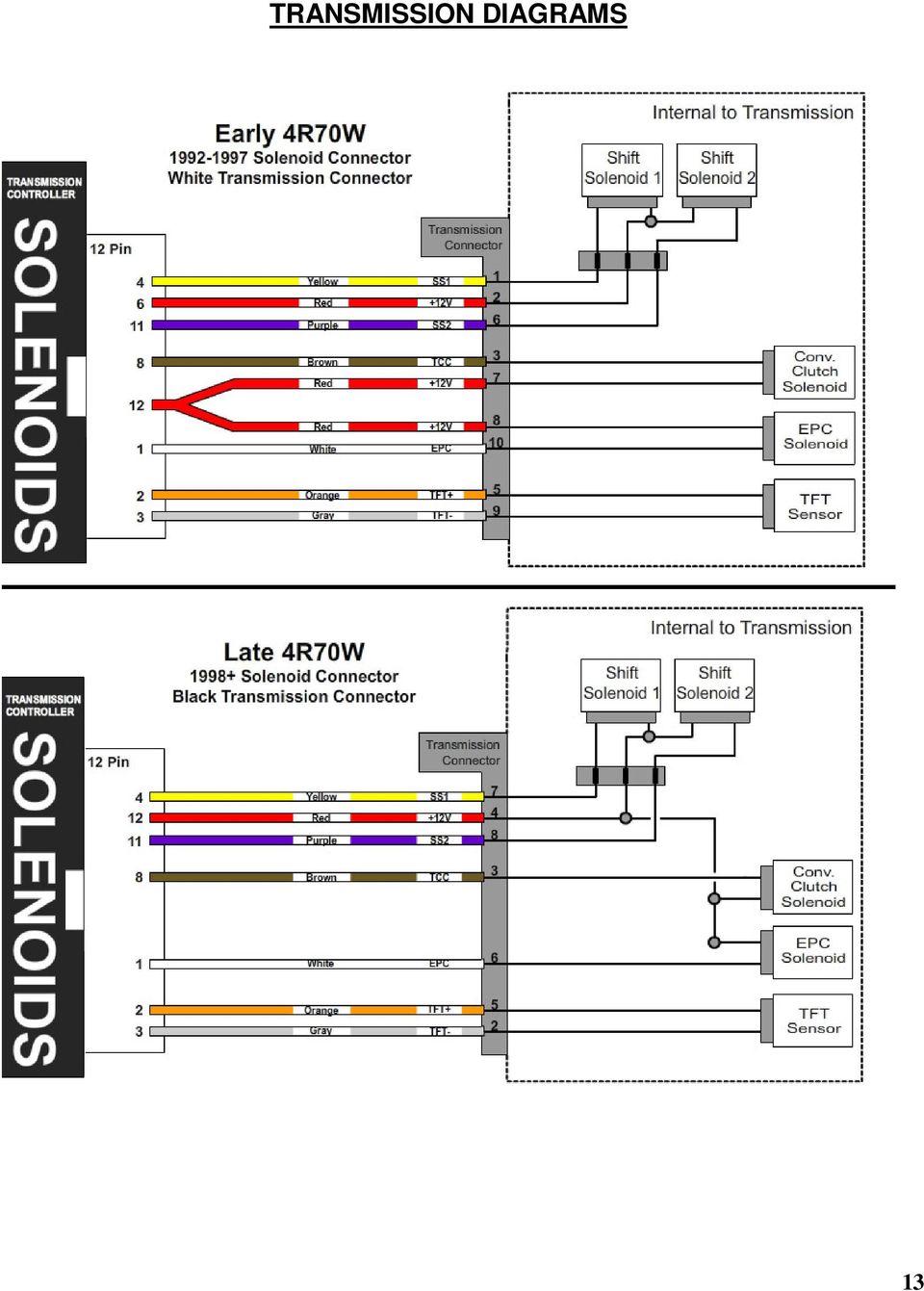
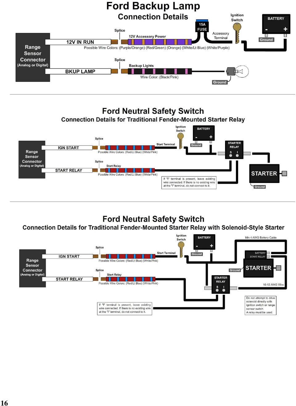
8 Step 4: Transmission Connectors Connect the Solenoid, PRNDL, and TSS cable to the transmission. If your transmission has two TSS connectors, connect the TSS cable to the output shaft speed sensor. Additionally, connect the Neutral Safety Switch and the Backup Lamp Switch (See page 16). Step 5: Optional Features Connect any extra features you wish to use. See the "Optional Features" section for details. 8

9 SETTING UP THE QUICK 1 Step 6: Calibration For a detailed video walkthrough of the setup process, scan the QR code to the right using your smart phone. You can also find the video on USshift.com. Verify that the correct calibration is loaded on the Quick 1. A standard calibration specific to your order is loaded before shipment. However, if the transmission configuration has changed since the order was placed, you'll need to connect the Quick 1 to a Windows PC and install the Shiftware Tuning Software. (See the Shiftware section for installation instructions.) Using the software, load the calibration that matches your transmission's configuration. 9

10 Step 7: Throttle Position Sensor Calibration Set the Closed Throttle and Full Throttle Positions. This step should be done with the ignition turned to ON, but the engine off. The engine should also be warm. Turn the knob to Tune (tne) and click once. Closed Throttle Position (CtP) should be displayed. Leave the accelerator untouched. Click the knob once, then double-click to set the current Closed Throttle Position. Click again to exit. Turn the knob to Full Throttle Position (FtP). Hold the accelerator all the way down. Click the knob once, then double-click to set the current Full Throttle Position. Click again to exit. Turn the knob to Save and Exit (SAE). Click once to save and exit. 10

11 NOTES ON INSTALLATION General Installation: The Quick 1 unit should be mounted within the passenger compartment of the vehicle in a protected location. Good mounting areas include under the dash, behind a kick panel, or under the seat, as long as the unit and wiring are not subject to damage. Under-hood mounting is NOT possible with the Quick 1 unit. It is not waterproof or rated for under-hood temperatures. Passenger compartment mounting is also necessary to provide easy access to the USB port, which is used to interface with a PC for programming and diagnostics, as well as the display and function control knob. For this reason, be sure to mount the unit in a way that gives easy access to the USB port, knob, and display. If you will be using a desktop PC for programming, install the unit so that it can be unplugged and moved easily. All electrical connections should be made using 60/40 rosin core solder. Cover the connection with heat-shrinkable tubing for improved insulation and mechanical strength. Individual connector terminals can be connected using a piggy-back method, where the terminal is removed from the plastic connector housing to allow the new wire to be soldered on to the terminal atop the original wire. Two wires may be connected together by twisting them together longitudinally, soldering, then covering with the appropriate size heat-shrink tubing. Before Driving the Vehicle: Start the engine and move the shifter through all positions, ensuring that the gear position and all sensor readings shown on the controller are correct. Most importantly, make sure that no error codes are shown on the Quick 1 display. It is a good idea to periodically check the Quick 1 display for errors as you drive, so it is wise to consider an accessible mounting location. If any error codes or unexpected characters are displayed, please refer to the user interface manual for detailed explanations. If possible, perform a line pressure check to ensure that line pressure is correct at idle (typically 60-80PSI), and that it smoothly increases toward maximum (typically PSI) as the throttle position increases. If you have any questions about the installation or line pressure readings, please contact our technical support department. 11

12 Adaptation for Factory-Equipped Transmissions: It is possible to use the Quick 1 controller in a vehicle which was originally equipped with one of the intended transmissions. This could be done in conjunction with an engine management system upgrade that no longer supports the transmission. Use of the TCS for this purpose allows flexibility in choosing the engine management system, in addition to the increased control, performance, and transmission durability afforded by Quick 1. If you retain the stock PCM/VCM, it can probably be modified or re-flashed to disable the transmission functionality. Identifying the Terminals of an Unknown Throttle Position Sensor: This is a procedure for identifying the correct terminal connections of any potentiometer-style throttle position sensor (almost all three-terminal TP sensors). A DVOM or analog Ohmmeter is required. 1. Set the meter to resistance mode and set it to a scale that can read up to 10K or 20K Ohms (if it is not auto-ranging). Please keep in mind when setting up and reading the meter that "K" means thousands of Ohms. In other words, 15K Ohms is the same as 15,000 Ohms. 2. Connect the meter to two pins at a time while operating the lever or cam of the TPS. Watch the meter while rotating the sensor. Check all three pairs of pins until you find a pair that does not change resistance when you rotate the sensor. The two pins that do not change resistance are the fixed ends of the resistance element (+5V and ground). The remaining pin that did change is known as the "wiper". It is the moving contact that slides along the resistance element to give the varying voltage. This is the output terminal of the sensor and should be connected to our green wire (Vehicle pin 3). 3. Next, with the sensor at the idle or closed throttle position, measure the resistance between the wiper (output) and each of the end terminals (the two whose resistance did not change in step 2) of the sensor. The end terminal with the lowest resistance to the wiper (at idle) is the ground terminal, and should connect to the black main ground wire of the controller (Vehicle pin 16). The terminal with the higher resistance to the wiper is the 5 volt reference input to the sensor and should connect to the orange wire (Vehicle pin 11) in our harness. General Guidelines for setting up Throttle Position Sensors: The linkage to a throttle position sensor should use most of the rotating range of the throttle position sensor. This can be adjusted by changing the ratio of the linkage. Also, please make sure that a small amount of the sensor's travel is being used at idle. You will want a TPS voltage at idle of at least 0.35 volts. This is done to allow the controller to detect problems with the TP sensor. For instance, if the sensor becomes disconnected or the linkage falls off, the TPS voltage will fall below the set idle threshold. If the TPS voltage goes below the idle threshold, the controller assumes that the TPS is bad and will switch to failsafe line pressure and default shift points. This is done to prevent damage to the transmission from low line pressure and will provide a safe "limp home" mode. 12

13 TRANSMISSION DIAGRAMS 13
14 14

15 15


16 16

17 17

18 OPTIONAL FEATURES Table Select: The table selection switch should be an On-Off type switch (such as a toggle or latching push-button switch) which applies ground to the table select input at Vehicle connector pin 5 when turned on. When the switch is turned on, the TCS will use the secondary calibration tables, allowing a completely different calibration to be selected for the transmission at any time. The Table Selection input may also be connected to a nitrous oxide system to provide an alternate calibration for use when the nitrous system is engaged. Other uses for this input include a Sport/Economy switch or a Normal/Aggressive switch. The usefulness of this input is limited only by your imagination. Speedometer Output: We have provided an adjustable speed signal output that can be used to drive an electronic speedometer, if desired. Use of this output signal is not necessary, but it can be helpful if your speedometer can not be driven correctly from another source. This signal can also be corrected for different gear ratios and tire heights, so it can be very useful in some applications. The speedometer output signal is normally provided as a 5 Volt square wave, but it can also be configured to provide a 12 Volt square wave when required (please refer to the "jumper settings" document for more information). There are two speedometer output modes that can be selected via the tuning software or the built-in tuning interface. It can also be disabled if not used. In the replicated speed sensor output mode, the speedometer output provides an amplified and squared version of the original speed sensor signal. Replicated mode is useful for applications that require a signal with the exact pulse rate of the speed sensor being used. There is also an adjustable corrected mode, which is very useful for correcting speedometer errors, or providing unusual speedometer output signal frequencies. Adjustable mode is essentially the electronic equivalent of a ratio corrector gear box for a mechanical speedometer. In adjustable mode, the correction factor is entered as a decimal number. The correction factor is the frequency ratio of the speedometer output frequency to the speed sensor frequency. This number can be easily adjusted to synchronize the vehicle speedometer to a GPS or other instrument. 18

19 In some cases, such as driving the input of an engine control ECU, the 0-5 Volt (or 0-12 Volt) square wave signal will not be able to properly drive the device that it is connected to. This is because some devices are only designed to accept an input signal from a variable reluctance (magnetic coil) sensor. Because of this, they may expect the input signal to swing below ground (0 Volts). To drive this type of input, use the included capacitor to "offset" the DC value of the speedometer signal to 0 Volts. As a result, the driven device will see a -2.5V to +2.5V signal instead of 0V to 5V. To make this signal work, install the provided 10µF, 25v, non-polar, electrolytic capacitor inline between the speedometer output of the Quick 1 and the device that it is driving. To install the capacitor, cut the speedometer output wire and solder a capacitor lead to each of the two cut wires. Overdrive On-Off Switch: The Overdrive switch can be used to turn overdrive on or off. The switch can be a latching switch (toggle switch, latching push-button, etc.) or a momentary type switch (spring-loaded push-button switch, spring-loaded toggle switch, etc.) connected to +12v ignition-switched power and pin 4 (brown) of the vehicle harness. (The tan wire on pin 12 is for VSS output and shouldn t be confused with the brown wire on pin 4 for the O/D switch.) Optionally, you can add an O/D indicator lamp between +12v ignition-switched power and pin 2 (white) of the vehicle harness. This lamp will normally light up when overdrive is off. This setting can be configured under the Driver Control Switch Settings tab of the tuning software. To use an LED bulb for the O/D light (without built-in resistors for 12v), connect the cathode (-) lead to the white wire on pin 2 of the vehicle harness and the anode (+) lead to +12v ignition-switched power. Put a resistor in series on either side. We recommend using a 1.2k Ohm resistor, but you can use one with a lower resistance to make the LED brighter or one with a higher resistance to make it dimmer. It s best to stay above 1k Ohm to protect the LED. A 1/4w resistor or higher is recommended. 19


20 20

21 MANUAL SHIFT CONNECTIONS Manutronic Overview: If connected and enabled in the software, the ManuTronic feature will allow manual selection of all forward gears using paddles, push-buttons, or another type of switch. With ManuTronic engaged, a brief press of the UPSHIFT button will change to the next higher gear, while DOWNSHIFT will change to the next lower gear. ManuTronic also has a safety feature which inhibits downshifting if the engine RPM is too high, which prevents over-revving of the engine due to a driver's error. Manutronic Reference Supply (JW2-5) There are several different ways to configure the Manutronic to meet your specific needs. Depending on your Manutronic configuration, you may need to install or uninstall the Manutronic jumper (JW2-5). You can find the jumper settings manual on the Quick 1 software disc in PDF format. This jumper supplies 5V to the Manutronic 1 input and should be installed for all Manutronic configurations (except for a Ford cruise control system). See the sections below for further explanation. 21
 The Light Blue wire is not needed for this configuration.")
22 Ford Cruise Buttons: For this configuration, you will need to solder the Dark Blue wire (Pin 14 on the Vehicle Connector) to the Blue / Black striped wire that connects the steering wheel buttons to the cruise module. (Follow the guidelines for soldering found in the General Installation section.) The Light Blue wire is not needed for this configuration. The Manutronic jumper should not be installed in the Quick 1 controller. Be sure to use the correct settings in the Shiftware setup. To enable the Manutronic, double-click the CRUISE OFF button. Press ON or OFF once to disable it. 22
 The Light Blue wire is not needed for this configuration.")
23 Ford Cruise Buttons without Cruise Module: For this configuration, you will need to connect the Dark Blue wire (Pin 14 on the Vehicle Connector) to the steering wheel buttons. (Follow the guidelines for soldering found in the General Installation section.) The Light Blue wire is not needed for this configuration. Remember that the Manutronic jumper must be installed in the Quick 1 controller and the correct settings used in the Shiftware setup. To enable the Manutronic, double-click the CRUISE OFF button. Press ON or OFF once to disable it. 23
 to your up-shift button (momentary).")
24 Momentary Shift Buttons with Latching On / Off Switch: For this configuration, you will need to connect the Dark Blue wire (Pin 14 on the Vehicle Connector) to your down-shift button (momentary) and connect the Light Blue wire (Pin 6 on the Vehicle Connector) to your up-shift button (momentary). To connect the on / off switch (latching), solder the switch's wire onto the Dark Blue down-shift wire with a 680 Ohm resistor between them. (Follow the guidelines for soldering found in the General Installation section.) Remember that the Manutronic jumper must be installed in the Quick 1 controller and the correct settings used in the Shiftware setup. Manutronic will be enabled when the toggle switch is turned on and disabled when it is turned off. 24
 to your up-shift button (momentary).")
25 Momentary Shift Buttons with Momentary On / Off Switch: For this configuration, you will need to connect the Dark Blue wire (Pin 14 on the Vehicle Connector) to your down-shift button (momentary) and connect the Light Blue wire (Pin 6 on the Vehicle Connector) to your up-shift button (momentary). To connect the on / off switch (momentary), solder one side of the switch onto the Dark Blue down-shift wire and the other side to the Light Blue up-shift wire. (Follow the guidelines for soldering found in the General Installation section.) Remember that the Manutronic jumper must be installed in the Quick 1 controller and the correct settings used in the Shiftware setup. To enable the Manutronic, press the On/Off button once and do the same to disable it. 25
 to COM1 of the receiver.")

26 Twist Machine Shrifter TM : For this configuration, you will need to connect the Dark Blue wire (Pin 14 on the Vehicle Connector) to COM2 of the receiver and connect the Light Blue wire (Pin 6 on the Vehicle Connector) to COM1 of the receiver. You can use either a momentary push-button on / off switch or a latching toggle on / off switch. (Refer to the previous two sections on how to install and use the on / off switch.) Remember that the Manutronic jumper must be installed in the Quick 1 controller and the correct settings used in the Shiftware setup. 26
27 SHIFTWARE Introduction: Using the Shiftware software allows you to modify the way your Quick 1 Transmission Control System behaves. You can customize shift-points as well as monitor and diagnose the Quick 1 unit in real-time. Setup: To create a calibration for the Quick 1, it is best to start with one of the standard calibrations which are included with the software. To load a standard configuration for your transmission, click the Open button on the toolbar, then browse to the folder where the transmission calibration files are located. (Default location is C:\BTS\) The files are named according to the transmission and RPM range and have the.btc file extension. Choose the calibration file and click Open. Once the calibration file is loaded, click the System Settings button on the toolbar to check the settings and make sure that they are correct for your transmission. The System Settings window has several tabs within it. Click each one to see each section of settings specific for your transmission. The System Settings Window 27
28 Customize: The main window is where all of the shift points and line pressure editing is done. The graph displays the up-shift and down-shift speeds in relation to throttle position for each shift. It also displays the line pressure curve (otherwise known as the EPC current) in relation to throttle position. The lower the line pressure curve is on the graph, the higher line pressure will be. You can use the checkboxes on the right to turn on the curves for individual shift firmness and adjust them independently. 28 The Main Window You can get help on anything by clicking the Question button (or the F1 key) and then clicking on an item. This can be used in any area of the software. The help messages in the settings pages are transmission-specific and are more like getting professional advice than normal help tips. The graph has ten points from left to right, 0 being idle and 9 being Wide-Open- Throttle (WOT). On the left side of the graph is speed in miles per hour. Click on a point in the graph to select it. (If Automatic Down-shift is enabled, then the corresponding down-shift point will be automatically selected along with the upshift point. This can be turned off by clicking the Downshift Select checkbox on the right.) You can select multiple points by holding CTRL while clicking the points, or a range of points by holding SHIFT and clicking the two points on each end. You can move between adjacent points using the LEFT and RIGHT arrow keys. Once a point (or points) is selected, you can drag it with the mouse to raise and lower its value. A yellow box will appear in the graph telling you what the value of the point is.
29 Tables: You can create more than one calibration, and use the Table buttons on the toolbar to select whether the current calibration file will be read from or written to table 1 or 2. The two table spaces in the controller are separate and independent, and each can hold a separate calibration file. An optional Table Select Switch can be added to the Quick 1 system to switch between them. (See Optional Features ) Save & Load: Once you have created your calibration, you can save the file to your hard drive or an external storage device. To save, click the Save button on the toolbar. Then browse to the location where you want it saved and click Save. Use Save As under the FILE menu to leave the original file unchanged and create a new version. Type the desired filename and click Save. Files are saved with a.btc extension. To load a calibration file, click the Open to the file and click Open. button on the toolbar. Then, browse Writing a Calibration to the Quick 1: For the changes you've made to take effect on the Quick 1 TCS, you first must write the calibration to the unit. Connect the Quick 1 to your computer using a standard USB cord (Type A to Type B). First, select the table you wish to write to the Quick 1 unit by clicking either the 1 or 2 buttons on the toolbar. Then, click the Write Calibration button on the toolbar. Once the Shiftware is finished writing the calibration, you can repeat these steps for the other table. When the Quick 1 unit is disconnected from the computer, the Write Calibration button will be grayed out. 29
30 IMPORTANT INFORMATION How to Avoid Errors: The Shiftware software gives you complete freedom and flexibility to customize your shifting calibration however you want. This freedom requires diligence to avoid errors. It is very important that the up-shift and down-shift curves for a given gear do not cross. The up-shift point at any throttle position should usually be at least 15% greater than the down-shift point. For instance, if the 2-3 up-shift point at ½-throttle is 45MPH, then the 3-2 down-shift point should usually be less than 40MPH. The On-Off differential between up-shift and down-shift points is called Deadband (also known as Hysteresis). The more deadband you use for your shift points, the more stable the system will be. Not using enough deadband can result in erratic shift behavior. Too much deadband will result in sluggish behavior due to a reluctance to down-shift. Pay close attention to the interaction between different shifts. Overlapping the 1-2 and 2-3 shifts can cause skipped gears and other drivability problems. Also note that torque converter slip at low speeds renders engine RPM values meaningless. It is usually desirable to have light-throttle shift points within a low RPM range. In this case, it is best to base light-throttle shift points on vehicle speed, rather than engine RPM (as most auto manufacturers do). 30
31 TROUBLESHOOTING WARNING! If the transmission does not begin to operate correctly within the first few feet of the road test, STOP immediately, check the troubleshooting guide, and call Baumann Electronic Controls if you need assistance. In some cases, just a few blocks of operation with low fluid pressure can destroy a transmission. Error Codes: The following error codes will be shown on the controller's display when faults are detected. For more detailed error messages, you can also view the Controller Fault Display in the tuning software. The software is not limited to currently set faults, but can show fault history as well. History is cleared when the controller powers down completely (ignition turned off and USB cable removed from computer.) Scan the QR Code to be directed to the corresponding troubleshooting guide webpage or visit t1x.us. OCP Pressure control solenoid overcurrent error (Pressure control disabled, max line pressure) t1x.us/113 OC1 Overcurrent error in solenoid bank 1 (Outputs disabled) t1x.us/114 OC2 Overcurrent error in solenoid bank 2 (Outputs disabled) t1x.us/115 OC3 Overcurrent error in solenoid bank 3 (Outputs disabled) t1x.us/116 F:tP Throttle position sensor value has dropped below the minimum (idle) voltage setting t1x.us/110 F:rS There are several errors which can cause this code to appear. The Controller Fault Display in the tuning software will differentiate between all of the errors listed which show the F:rS error code on the controller. Analog range sensor voltage or PWM duty cycle is out of tolerance, but is within approximate range for a given position. Controller is configured for a PWM range sensor, but no PWM signal was detected. Digital range sensor signal combination is not valid. Analog range sensor voltage or PWM duty cycle below low limit (Possible short to ground). Analog range sensor voltage or PWM duty cycle above high limit (Possible open sensor). Ford digital range sensor analog window voltage is too low (Possible short on TR3A pin). Ford digital range sensor analog window voltage is too high (270 Ohm resistor on TR3A pin not detected) t1x.us/103 31
32 Contact If you have any questions, problems, or product orders, don t hesitate to call our customer service line. (864) (Monday-Friday 10AM-6PM EST). If no one is available, please leave a detailed message and we will reply promptly. Whenever possible, we will try to return urgent technical support calls left after hours or over the weekend. You can also customer service at [email protected] Scan this code to copy the customer service phone number and address to your phone. 32
Electronic Power Control
 Service. Self-Study Programme 210 Electronic Power Control Design and Function With the Electronic Power Control system, the throttle valve is actuated only by an electric motor. This eliminates the need
Transmission electronic controls outline. Inputs- processing- outputs
 Transmission electronic controls outline Inputs- processing- outputs Inputs provide the system the environmental conditions that are needed to operate or check the operation of the transmission. Inputs
VEHICLE SPEED CONTROL SYSTEM
 PL VEHICLE SPEED CONTROL SYSTEM 8H - 1 VEHICLE SPEED CONTROL SYSTEM TABLE OF CONTENTS page DESCRIPTION AND SPEED CONTROL SYSTEM...1 SPEED CONTROL SERVO-PCM OUTPUT....2 SPEED CONTROL SWITCHES PCM INPUT...2
INSTRUMENT PANEL. 1995 Volvo 850 DESCRIPTION & OPERATION. 1995-96 ACCESSORIES & EQUIPMENT Volvo Instrument Panels
 INSTRUMENT PANEL 1995 Volvo 850 1995-96 ACCESSORIES & EQUIPMENT Volvo Instrument Panels 850 WARNING: When working around steering column and before performing repairs, disconnect and shield battery ground
TOYOTA ELECTRONIC CONTROL TRANSMISSION
 Electronic Control Transmission (ECT) The Electronic Control Transmission is an automatic transmission which uses modern electronic control technologies to control the transmission. The transmission itself,
Signature and ISX CM870 Electronics
 Signature and ISX CM870 Electronics Cummins West Training Center System Description General Information The Signature and ISX CM870 engine control system is an electronically operated fuel control system
TOYOTA ELECTRONIC TRANSMISSION CHECKS & DIAGNOSIS
 Checks and Adjustments The transmission requires regular maintenance intervals if it is to continue to operate without failure. As we discussed in previous sections, transmission fluid loses certain properties
QUICK START GUIDE 199R10546
 QUICK START GUIDE 199R10546 1.0 Overview This contains detailed information on how to use Holley EFI software and perform tuning that is included within the software itself. Once you load the software,
AUTOMATIC TRANSMISSION IN-CAR DIAGNOSTICS
 Learning Guide CHASSIS ELECTRICAL SPECIALIST AUTOMATIC TRANSMISSION IN-CAR DIAGNOSTICS COURSE NUMBER: C050-01 Notice Due to the wide range of vehicles makes and models, the information given during the
well as pulses from a magnetic driveshaft sensor or a magnetic speedometer cable sensor.
 1. Overview The Maximizer 4 progressive nitrous controller operates one or two separate stages of nitrous based on either time, RPM, MPH, throttle percentage or boost pressure. Whether your engine is naturally
A/C-HEATER SYSTEM - AUTOMATIC
 A/C-HEATER SYSTEM - AUTOMATIC 1995 Volvo 850 1995-96 Auto. A/C-Heater Systems Volvo 850 * PLEASE READ THIS FIRST * WARNING: To avoid injury from accidental air bag deployment, read and carefully follow
INSTALLATION INSTRUCTIONS BOOST CONTROLLER. Pro Control Input (Optional) Tach. Signal. Speed. Gray. Signal. Green Blue. Orange.
 Tach. Signal. Speed. Gray. Signal. Green Blue. Orange.") 2650-1706-00 INSTALLATION INSTRUCTIONS BOOST CONTROLLER WARNING! The installation of the Auto Meter Boost Controller is recommended only for experienced technicians. This product may damage your engine
2650-1706-00 INSTALLATION INSTRUCTIONS BOOST CONTROLLER WARNING! The installation of the Auto Meter Boost Controller is recommended only for experienced technicians. This product may damage your engine
RECOMMENDED TOOLS PERSONAL & VEHICLE PROTECTION SAFETY GLASSES
 PART NUMBER: 250-9612 GENERAL APPLICABILITY THIS CRUISE WAS TESTED AND VERIFIED ON: FORD FOCUS SE & S MODELS (AT/MT) FORD TRANSIT ALL MODELS RECOMMENDED TOOLS PERSONAL & VEHICLE PROTECTION SAFETY GLASSES
RECOMMENDED TOOLS PERSONAL & VEHICLE PROTECTION SAFETY GLASSES
 HYUNDAI ACCENT 2010- /ELANTRA 2012- / KIA RIO 2012- PART NUMBER: 250-9628 GENERAL APPLICABILITY THIS CRUISE WAS TESTED AND VERIFIED ON: (AT/MT) VEHICLES RECOMMENDED TOOLS PERSONAL & VEHICLE PROTECTION
Contents Installing the ucal Software on your PC/Laptop ucal Programmer Version Connecting the ucal Programmer to your PC/Laptop
 Contents Installing the ucal Software on your PC/Laptop 1 ucal Programmer Version 1 Connecting the ucal Programmer to your PC/Laptop 1 Optional USB Adapter Kit (for ucal) 1 Installing the USB Driver for
Electronically Controlled Air Suspension (ECAS) for Trucks
 for Trucks") $2.50 Electronically Controlled Air Suspension (ECAS) for Trucks Maintenance Manual No. 36 Issued 7-99 ECAS System for 6 x 2 and 6 x 4 Vehicles with Rear Air Suspensions Service Notes Service Notes This
$2.50 Electronically Controlled Air Suspension (ECAS) for Trucks Maintenance Manual No. 36 Issued 7-99 ECAS System for 6 x 2 and 6 x 4 Vehicles with Rear Air Suspensions Service Notes Service Notes This
CAN BUS INTERFACE. Module Information
 Part no: CB-1 The CAN Bus interface is designed to provide a vehicle speed signal for vehicles using a CAN Bus system. It is programmed to automatically detect the vehicle type and it will give a frequency
Electrical Systems - IQAN Digital Control System. IQAN Control System Components... 5.1.3
 Section 5.1 Electrical Systems - IQAN Digital Control System IQAN Control System Components........................... 5.1.3 IQAN Operational Description: At Machine Startup.....................................
Introduction. Drenth Motorsport Gearboxes Fleuweweg 10 7468 AG Enter The Netherlands Phone: +31 (0)547 38 26 96 Fax: +31 (0)547 38 20 65
547 38 26 96 Fax: +31 (0)547 38 20 65") 25.03.0023 Introduction The display comes with a software application. With the software application information shown on the display can be adjusted. There are different modes to adjust: the shape of
25.03.0023 Introduction The display comes with a software application. With the software application information shown on the display can be adjusted. There are different modes to adjust: the shape of
Part Number: 250-1859
 General Applicability 2010 Honda Insight 07- Kia Optima / Forte / Rondo/ 10- Sedona / 12 Soul 10- Hyundai Tucson / Elantra Touring ETC 2012 Accent / Elantra/ Genesis Recommended Tools Safety Tools Gloves,
The Child Reminder System Installation Manual
 The Child Reminder System Installation Manual Revised June, 2006 Detailed installation information can be found at www.childreminder.com. Get through your installation quickly and easily by calling 1-888-330-6786
i ChatterBox! Motorcycle Security
 i Before you Start the Installation * Please read this manual to become familiar with the requirements necessary to complete the installation. * Use a high quality multi-meter to test all wires before
MAX ENERGY POWER PROGRAMMER PART #52001/52501 REFERENCE GUIDE AND INSTALLATION MANUAL ADDENDUM 2007-2010 JEEP WRANGLER WITH ENHANCED OFF-ROAD FEATURES
 MAX ENERGY POWER PROGRAMMER PART #52001/52501 REFERENCE GUIDE AND INSTALLATION MANUAL ADDENDUM 2007-2010 JEEP WRANGLER WITH ENHANCED OFF-ROAD FEATURES The following is a step by step guide for installing
Meritor WABCO Pneumatic Antilock Braking System (ABS) 42.22
 42.22") (ABS) 2.22 Troubleshooting WARNING Before testing a vehicle equipped with Automatic Traction Control (ATC) on a dynamometer, the ATC system must be disabled. See Subject 160 for instructions. Activation
(ABS) 2.22 Troubleshooting WARNING Before testing a vehicle equipped with Automatic Traction Control (ATC) on a dynamometer, the ATC system must be disabled. See Subject 160 for instructions. Activation
Essential Electrical Concepts
 Essential Electrical Concepts Introduction Modern vehicles incorporate many electrical and electronic components and systems: Audio Lights Navigation Engine control Transmission control Braking and traction
How to read this guide
 How to read this guide The following shows the symbols used in this Quick start guide with descriptions and examples. Symbol Description Example P oint Reference Caution [ ] This symbol explains information
1978-83 Malibu 1978-87 Monte Carlo 1978-87 El Camino
 Important facts about this kit. 1. The dash panel used in this picture is used by permission of Covan's Classic. 2. This kit requires some modification to your original under dash wiring harness. It is
Diagnosing Hydraulic Problems
 Diagnosing Hydraulic Problems 1 Problems A pressure test is a key check when you need to determine if a problem is caused by something that is inside or outside of the transmission. Low automatic transmission
Service Information CALIBRATION PROCEDURE AND TROUBLESHOOTING FOR LINEAR GOVERNOR CONTROLLERS NOTE
 Service Information Calibration & Adjustments CALIBRATION PROCEDURE AND TROUBLESHOOTING FOR LINEAR GOVERNOR CONTROLLERS Part Number DYN1-10752-000-0-12/24 DYN1-10752-001-0-12/24* DYN1-10753-000-0-12/24
PUSH BUTTON START INSTALLATION MANUAL
 PUSH BUTTON START INSTALLATION MANUAL ALTHOUGH THIS PRODUCT HAS BEEN THOROUGHLY TESTED KPIERSON TECHNOLOGIES ASSUMES NO RESPONSIBILITY FOR ANY DAMAGE THAT MAY RESULT BY THE INSTALLATION OF THIS PRODUCT.
1955-1956 Chevy Bel-Era
 Classic Instruments 1955-1956 Chevy Bel-Era Installation Manual Revised January 2, 2014 Page 1 Table of Contents Table of Contents 2 Welcome to the Team of Classic Instruments! 3 55-56 Chevy Part Identification
Service Manual Trucks
 Service Manual Trucks Group 36 Vehicle Electronic Control Unit (MID 144), Diagnostic Trouble Code (DTC), Guide From build date 1.2007 PV776-88951780 Foreword The descriptions and service procedures contained
Vehicle Monitoring Quick Reference Guide
 Vehicle Monitoring Quick Reference Guide Powered by Delphi Welcome You re about to experience a powerful device that will deliver a new level of convenience and peace of mind with your vehicle. When combined
KEYLESS ENTRY UPGRADE SECURITY SYSTEM for 2004 TOYOTA HIGHLANDER
 KEYLESS ENTRY UPGRADE SECURITY SYSTEM for 2004 TOYOTA HIGHLANDER DEALER SERVICE AND INSTALLATION MANUAL KIT NO. 00016-30915 Contents PARTS LIST... 2 PARTS ILLUSTRATIONS... 2 VEHICLE PREPARATION... 3 INSTALLING
Electronically Controlled Clutchless or Variable Drive Compressors
 Electronically Controlled Clutchless or Variable Drive Compressors On many new air conditioning systems, such as Lexus, Cadillac, Chrysler, and others, a new type of compressor has been fitted. There are
SERVICE BULLETIN No.1103
 SERVICE BULLETIN No.1103 Circulate to listed addressees COACH MODEL BULLETIN TYPE MANUAL & SECTION PARTS BOOK REVISION : T 2100 and C2000 Series : Service Information : Maintenance Manual: Chapter 3 Drive
Typical ECM/PCM Inputs
 Typical ECM/PCM Inputs The computer system components fall into two categories: sensors (inputs) and controlled components (outputs). Each system has sensors. Not every system has all the ones listed,
OIL PRESS 71.8 PSI FUEL. Cloud based, diagnostic, engine monitoring and reporting system. www.faria-instruments.com www.beede.com
 OIL PRESS 71.8 PSI Cloud based, diagnostic, engine monitoring and reporting system www.faria-instruments.com www.beede.com Start Updating Send Data The Faria EntelNet service is a multi part system which
How To Fix A 2000 Dually Ram 2000-04 Dually Dually 2.4 (Dodge Ram)
") 21-Jun-02 ValveBody #1030418/419 1 DODGE RAM 47RE TRANSMISSION (#1030418) 48RE TRANSMISSION (#1030419) BD VALVE BODY INSTALLATION MANUAL IMPORTANT READ ALL INSTRUCTIONS BEFORE INSTALLATION 21-Jun-02 ValveBody
21-Jun-02 ValveBody #1030418/419 1 DODGE RAM 47RE TRANSMISSION (#1030418) 48RE TRANSMISSION (#1030419) BD VALVE BODY INSTALLATION MANUAL IMPORTANT READ ALL INSTRUCTIONS BEFORE INSTALLATION 21-Jun-02 ValveBody
CurveMaker v2.1 DYNAFS programmable ignition software
 CurveMaker v2.1 DYNAFS programmable ignition software Dynatek 164 S Valencia St. Glendora CA 91741 phone (626)963-1669 fax (626)963-7399 Contents 1) Installation...1 2) Overview...1 3) Programming a Curve...4
CONTINUOUSLY VARIABLE TRANSMISSION (CVT)
") GROUP 23 CONTINUOUSLY VARIABLE TRANSMISSION (CVT) CONTENTS CVT........................... 23-2 GENERAL INFORMATION............. 23-2 ELECTRONIC CONTROL SYSTEM...... 23-3 EEPROM...........................
GROUP 23 CONTINUOUSLY VARIABLE TRANSMISSION (CVT) CONTENTS CVT........................... 23-2 GENERAL INFORMATION............. 23-2 ELECTRONIC CONTROL SYSTEM...... 23-3 EEPROM...........................
Lectric Enterprises 5905 Sprucepine Drive Winston Salem, NC. 27105 Telephone 336-655-4801 e-mail: [email protected]
 KNIGHT RIDER DASH ELECTRONICS PILOT\SEASON 2-2 TV DASH INSTALLATION INSTRUCTION MANUAL Bezel Overlay Voice Box Instructions Relay connection for a dash startup delay. Connect to the +12v side of relay
Electronic Manual Gearbox
 Service. Self-Study Programme 221 Electronic Manual Gearbox Design and Function Taking the Lupo as the basis, Volkswagen has developed the world's first 3 L car that will also go into volume production.
Troubleshooting. Appendix B. B.1 Chrysler Communications Problems. B.1.1 Common Vehicle Problems. Engine (Except LH Models)
") Troubleshooting This chapter contains manufacturer-specific information for troubleshooting problems with scan tool-to-vehicle communications. For general troubleshooting information, see the user s manual
Troubleshooting This chapter contains manufacturer-specific information for troubleshooting problems with scan tool-to-vehicle communications. For general troubleshooting information, see the user s manual
EVBIKE LCD Display Control User Guide. EVBIKE LCD Display Control User Guide WWW.EVBIKE.CZ - 1 -
 EVBIKE LCD Display Control User Guide WWW.EVBIKE.CZ - 1 - Table of Contents: 1) Description of the individual components and installation 2) Description of the measured quantities and user control display
WARRANTY AND DISCLAIMER
 2036 Fillmore Street Davenport, Ia. 52804 563-324-1046 www.racedigitaldelay.com MEGA 350/450 WARRANTY AND DISCLAIMER DIGITAL DELAY INC. WARRANTS THE PRODUCTS IT MANUFACTURES AGAINST DEFECTS IN MATERIALS
Diagnosing and Understanding Starting Problems on the ZR-1 Marc Haibeck 28-Sep-13
 Diagnosing and Understanding Starting Problems on the ZR-1 Marc Haibeck 28-Sep-13 There are three basic failure conditions: - A VATS security system lockout - A click from the starter solenoid but no engine
RACEAIR REMOTE PAGER SYSTEM
 Computech Systems, Inc. 301-884-5712 30071 Business Center Dr. Charlotte Hall, MD 20622 RACEAIR REMOTE PAGER SYSTEM TM Introduction: Computech s RaceAir Remote Competition Weather Station with the Data
Electrical Circuit Theory
 Electrical Circuit Theory Learning Objectives: 1. Review the basic electrical concepts of voltage, amperage, and resistance. 2. Review the components of a basic automotive electrical circuit. 3. Introduce
MODEL 5010 DUAL CHANNEL SMOKE/FIRE DETECTION MODULE
 DESCRIPTION MODEL 5010 DUAL CHANNEL SMOKE/FIRE DETECTION MODULE DESCRIPTION The SST Model 5010 Two Channel Smoke/Fire Detection Module provides two independent detection input channels for the NOVA-5000
M.S Ramaiah School of Advanced Studies - Bangalore. On completion of this session, the delegate will understand and be able to appriciate:
 Transmission Control Lecture delivered by: Prof. Ashok C.Meti MSRSAS-Bangalore 1 Session Objectives On completion of this session, the delegate will understand and be able to appriciate: Rl Role of electronic
Servo Info and Centering
 Info and Centering A servo is a mechanical motorized device that can be instructed to move the output shaft attached to a servo wheel or arm to a specified position. Inside the servo box is a DC motor
DCX300 - DCX400 - DCX600
 Ph: 541-476-3565 Fax: 541-476-3566 DCX300 - DCX400 - DCX SEPARATELY EXCITED DC MOTOR CONROLLERS Alltrax motor controllers are designed to work with various golf cars from different manufacturers. Use the
CAUTION: CAREFULLY READ INSTRUCTIONS BEFORE PROCEEDING. NOT LEGAL FOR SALE OR USE IN CALIFORNIA OR ON ANY POLLUTION CONTROLLED VEHICLES.
 Twin Tec Installation Instructions for Twin Cam Ignition CAUTION: CAREFULLY READ INSTRUCTIONS BEFORE PROCEEDING. T LEGAL FOR SALE OR USE IN CALIFORNIA OR ON ANY POLLUTION CONTROLLED VEHICLES. OVERVIEW
AMS-1000 Multi-Channel Air Management System for Boost Control
 AMS-000 Multi-Channel Air Management System for Boost Control The terminal pin descriptions may also be viewed on screen. See Page 4 of manual for details. Clutch Input Shift Input Scramble Boost Input
USER MANUAL V5.0 ST100
 GPS Vehicle Tracker USER MANUAL V5.0 ST100 Updated on 15 September 2009-1 - Contents 1 Product Overview 3 2 For Your Safety 3 3 ST100 Parameters 3 4 Getting Started 4 4.1 Hardware and Accessories 4 4.2
Introduction to Electronic Signals
 Introduction to Electronic Signals Oscilloscope An oscilloscope displays voltage changes over time. Use an oscilloscope to view analog and digital signals when required during circuit diagnosis. Fig. 6-01
I Click on a link tab to jump to that page. Cover Page
 Publication, Duplication, or Retransmission Of This Document Not Expressly Authorized n Writing By The nstall Doctor s Prohibited. Protected By U.S. Copyright Laws. 1997,1998,1999,2000. Factory Radio Other
INSTALLATION MANUAL 3RP / 5RP 4-BUTTON SERIES VEHICLE SECURITY SYSTEMS
 3RP / 5RP 4-BUTTON SERIES VEHICLE SECURITY SYSTEMS INSTALLATION MANUAL Before you begin the installation Read the INSTRUCTIONS! Always use a multi-meter when verifying vehicle wiring. Before mounting the
WIRING HARNESS FOR AS635P4. BLUE PLUG RED, BLUE, BLACK, WHITE - Plug in dual stage sensor harness
 WIRING HARNESS FOR AS635P4 ANTENNA NOT USED 5 PIN WHITE PLUG 2 PIN WHITE PLUG GREEN - PARKING BRAKE INPUT (-) BLUE - NOT USED 3 PIN BLUE PLUG RED, BLUE, BLACK, WHITE - Plug in dual stage sensor harness
Lab 3 - DC Circuits and Ohm s Law
 Lab 3 DC Circuits and Ohm s Law L3-1 Name Date Partners Lab 3 - DC Circuits and Ohm s Law OBJECTIES To learn to apply the concept of potential difference (voltage) to explain the action of a battery in
Evaluation of the Automatic Transmission Model in HVE Version 7.1
 HVE-WP-2010-3 Evaluation of the Automatic Transmission Model in HVE Version 7.1 Copyright 2010 Engineering Dynamic Corporation Eric S. Deyerl, P.E., Michael J. Fitch Dial Engineering ABSTRACT The Automatic
ABS Flash Code (Blink Code) Instructions
 Instructions") ABS Flash Code (Blink Code) Instructions Innovative Products of America Incorporated Tinker Street, Woodsttock, NY 8 Local: 8-6-00 Toll Free: 888-86-8 Fax: 8-6-600 www.ipatools.com [email protected] ABS
ABS Flash Code (Blink Code) Instructions Innovative Products of America Incorporated Tinker Street, Woodsttock, NY 8 Local: 8-6-00 Toll Free: 888-86-8 Fax: 8-6-600 www.ipatools.com [email protected] ABS
The Charging System. Section 5. Charging System. Charging System. The charging system has two essential functions:
 The Charging System Charging System The charging system has two essential functions: Generate electrical power to run the vehicle s electrical systems Generate current to recharge the vehicle s battery
Cover Page. Factory Radio Other Documents Available For This Vehicle:
 & nstall Publication, Duplication, or Retransmission Of This Document Not Expressly Authorized n Writing By The nstall Doctor s Prohibited. Protected By U.S. Copyright Laws. 1997,1998,,2000. Factory Radio
SE05: Getting Started with Cognex DataMan Bar Code Readers - Hands On Lab Werner Solution Expo April 8 & 9
 SE05: Getting Started with Cognex DataMan Bar Code Readers - Hands On Lab Werner Solution Expo April 8 & 9 Learning Goals: At the end of this lab, the student should have basic familiarity with the DataMan
Vario Tractors - Fault Codes. Faults. all Vario tractors Tractor / General system. EDC / EMR bus fault. Fault in ECU Programming errors in ECU.
 12/1999 f 1/58 Vario Tractors - Codes 0000 000001 Date Version Page Capitel Index Docu-No. FCT_InitPage 0.0.11 A021; A022 Id rief description Description Consequences Link FENDIAS / Note ECU, EDC; ECU,
Installation instructions for VW Golf VII & Skoda Octavia III all models 2013 > Signals on CAN: Brake - Clutch - VSS
 EL-PAS -Cruise II Installation instructions for VW Golf VII & Skoda Octavia III all models 2013 > Signals on CAN: Brake - Clutch - VSS e-cruise www.lpdk.com LP Lindgaard Pedersen A/S Page 1 / 5 Before
Note: This information obtained from internet sources and not verified- use at your own risk!!!!
 Cummins Engine Diagnostic Fault Codes for 2003 and later engines (generally for 2004 and later Alpines; see page 13 for earlier engine diagnostic codes): Note: This information obtained from internet sources
Capacitive Touch Lab. Renesas Capacitive Touch Lab R8C/36T-A Family
 Renesas Capacitive Touch Lab R8C/36T-A Family Description: This lab will cover the Renesas Touch Solution for embedded capacitive touch systems. This lab will demonstrate how to setup and run a simple
Parts List. Navigation
 Parts List quantity description 1 LCD-200 Display 1 LCD-200 Display cable 1 CD-ROM 2 dual lock or velcro 1 1GB SD card (optional) 1 CAN termination plug Navigation Main Menu Begin Log/Stop Log page 4 Log
2007 W-SERIES (CHEVROLET & GMC) N-SERIES (ISUZU) 250 NPR/W3500, NPR HD/W4500, NQR/W5500, NRR/W5500-HD Diesel Electrical Symbols
 N-SERIES (ISUZU) 250 NPR/W3500, NPR HD/W4500, NQR/W5500, NRR/W5500-HD Diesel Electrical Symbols") 2007 W-SERIES (CHEVROLET & GMC) N-SERIES (ISUZU) 250 NPR/W3500, NPR HD/W4500, NQR/W5500, NRR/W5500-HD Diesel Electrical Symbols Symbol Meaning Symbol Meaning Symbol Meaning Fuse Electronic Parts Coil (Inductor),
2007 W-SERIES (CHEVROLET & GMC) N-SERIES (ISUZU) 250 NPR/W3500, NPR HD/W4500, NQR/W5500, NRR/W5500-HD Diesel Electrical Symbols Symbol Meaning Symbol Meaning Symbol Meaning Fuse Electronic Parts Coil (Inductor),
Installation Instructions
 Installation Instructions Windows USB driver for Installation If a Diagnostic Interface with USB is connected to a PC with a Windows operating system 98, ME, XP or Vista for the first time, it is necessary
I Click on a link tab to jump to that page. Cover Page
 & nstall Publication, Duplication, or Retransmission Of This Document Not Expressly Authorized n Writing By The nstall Doctor s Prohibited. Protected By U.S. Copyright Laws. 1997,1998,1999,2000. Factory
Installation Instructions For #63011 Striker Diesel MD Power Modules 2003-2007 Ford Powerstroke 6.0L Diesel Copyright
 2501 Ludelle Street Fort Worth, Texas 76105 817-244-6212 Phone 817-244-4024 Fax 888-350-6588 Sales 800-423-9696 Tech E-mail: [email protected] Web: www.painlessperformance.com Installation
GM HEI Timing Computer Instruction Manual. Overview of Features
 GM HEI Timing Computer Instruction Manual Overview of Features Convenient 2 5/8 round gauge package for easy Dash or Gauge Pod mounting No Laptop, PC or Palm Pilot necessary for programming (except for
Conversion of a 89-93 MAF 5.0 Mustang EFI Wiring Harness to Standalone Operation in Another Vehicle
 Conversion of a 89-93 MAF 5.0 Mustang EFI Wiring Harness to Standalone Operation in Another Vehicle 1. I ll assume that you already have a place to mount your EEC and that you ve already cut a hole in
ON-Board Diagnostic Trouble Codes
 ON-Board Diagnostic Trouble Codes The list below contains standard diagnostic trouble codes (DTC s) that are used by some manufacturers to identify vehicle problems. The codes provide below are generic
Multi Function, User Configurable Remote Vehicle Security System with 4 Button Replaceable Membrane Remote Transmitter
 MODEL PRO-9744 INSTALLATION MANUAL Multi Function, User Configurable Remote Vehicle Security System with 4 Button Replaceable Membrane Remote Transmitter This System Allows The Transmitter Buttons To Be
VS Commodore LPG installation utilising an LPG Memcal and Apexus Quick-kit.
 VS Commodore LPG installation utilising an LPG Memcal and Apexus Quick-kit. Description of the components and operation LPG/Petrol changeover switch The LPG change-over switch is mounted in the instrument
Mobile Satellite Solutions. A WiWorld Partner SATELLITE TV ANTENNA CONTROLLER RFM-1000/1100 TECHNICAL MANUAL STOW SEARCH
 Mobile Satellite Solutions A WiWorld Partner SATELLITE TV ANTENNA CONTROLLER RFM-1000/1100 TECHNICAL MANUAL SEARCH STOW Ver. 1 June 2012 WARNING Make all electrical and coax connections from the controller
1970-72 Chevelle. 1970-72 Chevelle. (500645) Gauge Cluster Kit Installation Instructions. (500645) Gauge Cluster Kit Installation Instructions
 Gauge Cluster Kit Installation Instructions. (500645) Gauge Cluster Kit Installation Instructions") 1970-72 Chevelle (500645) Gauge Cluster Kit Installation Instructions 1970-72 Chevelle (500645) Gauge Cluster Kit Installation Instructions STEP 1: There are 4 small gauges. This is a photo of the bare
1970-72 Chevelle (500645) Gauge Cluster Kit Installation Instructions 1970-72 Chevelle (500645) Gauge Cluster Kit Installation Instructions STEP 1: There are 4 small gauges. This is a photo of the bare
G-100/200 Operation & Installation
 G-100/200 Operation & Installation 2 Contents 7 Installation 15 Getting Started 16 GPS Mode Setup 18 Wheel Sensor Mode Setup 20 Fuel Calibration 23 Basic Operation 24 Telemetery Screen 27 Entering a Distance
Transporter Current Flow Diagram No. 80 / 1
 Transporter Current Flow Diagram No. 80 / 1 2.5 l/65 kw direct injection turbo diesel, engine code AJT From May 1999 2.5 l/75 kw direct injection turbo diesel, engine codes ACV, AUF 2.5 l/111 kw direct
Owner s Manual Ignition Upgrade Module for 2004-up Carbureted Harley Davidson Motorcycles P/N ASM5075
 Owner s Manual Ignition Upgrade Module for 2004-up Carbureted Harley Davidson Motorcycles P/N ASM5075 Thunder Heart Performance Corporation MANUAL P/N EI5075 120 Industrial Drive Revision 7/15/05 White
Networkfleet 3500 Product Line Installation Guide
 Networkfleet 3500 Product Line Installation Guide Light/Medium Duty (L3500) Heavy Duty (H3500) Universal (U3500) www.networkcar.com/fleet Customer Care: (866) 227-7323 [email protected] Table
Kelly KBS-L Brushless Motor Controller User s Manual
 Kelly KBS-L Brushless Motor Controller User s Manual Devices Supported: KBS24051L KBS24101L KBS24121L KBS36051L KBS36101L KBS48051L KBS48101L KBS48121L KBS72051L KBS72101L KBS72121L Rev.4.1 Jan. 2014 Chapter
Torque Convertor Control System. Part# 1030395
 3 November 2005 TorqLoc #1030395 1 BD TorqLoc Torque Convertor Control System Part# 1030395 Installation Manual for the following applications: BD Brakes for Dodge, Ford and Chevrolet Pac Brake for Dodge
User s Manual. Diagnostic and On-Screen Service Instructions For:
 Rev 01-04 User s Manual TOOLBOX TM SOFTWARE W H ME R I T O R A T Y O U WA B C O Diagnostic and On-Screen Service Instructions For: TOOLBOX Pneumatic ABS (D and E Versions) Trailer ABS (Easy-Stop TM and
A&A CORVETTE PERFORMANCE C6 BOOST & FUEL GAUGE INSTALLATION INSTRUCTIONS
 A&A CORVETTE PERFORMANCE C6 BOOST & FUEL GAUGE INSTALLATION INSTRUCTIONS 1. Check your gauges before you take them out of the packaging to make sure they are at 0 (zero) psi for both boost and fuel pressure.
QUICK START GUIDE. SG2 Client - Programming Software SG2 Series Programmable Logic Relay
 QUICK START GUIDE SG2 Client - Programming Software SG2 Series Programmable Logic Relay SG2 Client Programming Software T he SG2 Client software is the program editor for the SG2 Series Programmable Logic
MTX-D Ethanol Content and Fuel Temperature Gauge User Manual
 MTX-D Ethanol Content and Fuel Temperature Gauge User Manual P/N 3912 kit does not include flex fuel sensor. The ECF-1 is compatible with GM P/Ns 13577429 and 13577379 1. Installation... 2 1.1 Gauge Mounting...
REC FIM LOCKPICK INSTALLATION OPTIONS
 REC FIM LOCKPICK INSTALLATION OPTIONS TM PLUG INTO RADIO PLUG WHITE CONNECTOR INTO RADIO PLUG AND PLAY RADIO CONNECTORS UNPLUG ORIGINAL RADIO GRAY CONNECTOR THEN PLUG IN HERE AFTERMARKET FRONT CAMERA VIDEO
User Guide. Vehicle Diagnostics by Delphi
 User Guide Vehicle Diagnostics by Delphi Table Of Contents Welcome...9 Is My Vehicle Compatible?...9 Equipment Overview...10 Package Contents...10 System Requirements...11 Installation Requirements...11
FUEL-16, Troubleshooting Fuel Supply Problems
 FUEL-16, Troubleshooting Fuel Supply Problems Introduction This procedure is used to troubleshooting fuel supply problems including failure of the fuel pump to start during engine cranking. Fuel Pump Not
TS1 Ultra Sonic Tank Sender Training. 27 November 2007
 1 TS1 Ultra Sonic Tank Sender Training 27 November 2007 2 Topics TS1 Tank Sender TS1-PK Programming Kit TS1 Programming Software Programming TS1 Troubleshooting 3 TS1 TS1 is an advanced tank sender based
Technical Service Information
 Technical Service Information COMPLAINT: CAUSE: 1996-20 DEFINITIONS When a VW/Audi vehicle is exhibiting a symptom or is in fail-safe, the technician, in many cases, is unable to communicate with the on-board
Pressure Control Solenoid "D" Performance (Shift Solenoid Valve SLT)
") 750E UTOMIC TRNSMISSION UTOMIC TRNSMISSION SYSTEM 123 DTC DESCRIPTION P2714 Pressure Control Solenoid "D" Performance (Shift Solenoid Valve SLT) Line Pressure Control Pressure Current Flow to Solenoid
750E UTOMIC TRNSMISSION UTOMIC TRNSMISSION SYSTEM 123 DTC DESCRIPTION P2714 Pressure Control Solenoid "D" Performance (Shift Solenoid Valve SLT) Line Pressure Control Pressure Current Flow to Solenoid
Transmitter Interface Program
 Transmitter Interface Program Operational Manual Version 3.0.4 1 Overview The transmitter interface software allows you to adjust configuration settings of your Max solid state transmitters. The following