Introduction. Drenth Motorsport Gearboxes Fleuweweg AG Enter The Netherlands Phone: +31 (0) Fax: +31 (0)
|
|
|
- Julianna Bridges
- 8 years ago
- Views:
Transcription
1

2 Introduction The display comes with a software application. With the software application information shown on the display can be adjusted. There are different modes to adjust: the shape of the RPM indication and the duration of the engine cut can be controlled (power-shift). Beside this the gear indicator also gives information about which gear is selected. The settings of the DMS gearlever can also be calibrated with the display. This document contains information about the Drenth display. The user manual includes function descriptions, wiring diagrams and instructions to use the software that is included. Last modified: December 2012 Made by Arjan Hoogendijk Drenth Motorsport Gearboxes Fleuweweg AG Enter The Netherlands Phone: +31 (0) Fax: +31 (0) info@drenth-gearboxes.com 2

3 Function description The Advanced Display, which Drenth can supply, has the following options: Gearindication: The gear indicator displays the selected gear by measuring the position of the selector barrel with a rotary sensor. This function can be calibrated through the supplied software. Shiftlight The gear indicator can be used as a shiftlight when a preset level of RPM is reached. This preset level and the manner of indicating can be set with the supplied software. Flatshift The gear indicator can act as a flatshift system (powershift) This means that you can accelerate (full throttle) and shift up without using the clutch or lifting the throttle. The gear indicator provides a signal that can be used to make a engine cut for powershifting. It is possible to set different cut times in several gears with the supplied software. Throttle blip or reverse light With the supplied software there is the possibility to use the reverse light or the throttle blip. The throttle blip time can be adjusted for all the different gears separately in milliseconds. the use of a throttle blip gives the possibility for a smoother downshift. Set-up DMS Gearlever The set-up of the DMS Gearlever can be calibrated to your own specifications. The force which is needed to shift up and shift down can be adjusted in the loadcell. It s possible to use flat shifting for up shift and throttle-blip or the clutch for downshift. This manual describes the different options on how to use them. 3
 This means that you can accelerate (full throttle) and shift up without using the clutch or lifting the throttle.")
4 Connections 1. Power is supplied to the red (12 volt) and black wire (ground). So it doesn t matter which red wire is connected to the relay or the +12V because they are internal connected. The maximum voltage of the supply is 17-volt, the minimum is 9 volt. Make sure that the supply is free of interference (do not connect to ignition coil or starter). The ground must be directly connected to engine ground, do not place a switch in this wire. Disconnecting ground when the display is on can lead to permanent damage! 2. For the RPM pickup the gear indicator comes with 2 wires. You can use either one (not both) depending on car electronics and wire loom. We advise to start with the green wire as this can handle 1700 volts maximum. Connect the green wire to the negative side of the ignition coil. Otherwise use the pink wire to connect to the coil driver s (of the ignition system). Note that it can only handle 15 volts maximum. If this wire is overloaded the display is damaged. 3. The wires to connect the power shift are the yellow/black (signal) and white/black (ground). They must be connected to the switch that is mounted in the gearbox. It is actuated when the gearbox shifts up, the type of switch NO (Normally Open) or NC (Normally Closed) can be set in the software. Make sure that the switch is isolated from the gearbox. 4. Gear position wires are black/grey (ground), yellow/green (5 volts) and grey/blue for the signal. These go to the rotary sensor as follows: Cable display Function Cable rotary sensor Black / grey Ground Black Yellow / green 5 Volts Red Grey / blue Signal Depends on witch gearbox is used Gearbox: Evo IX Sequential EVO X sequential DG 400 DG 500 Evo Sequential Unit (38.07.xxxx) MPG Signal wire: Yellow Yellow White White White White 4
 depending on car electronics and wire loom.")
 and red (12 volt). Connect these to the coil of the relay. The switch of the relay is placed in the supply line to the ignition coil. 6.")
5 View rotary sensor: When shifting up, the shaft of the rotary sensor turns in the direction of the arrow. Wire: Yellow (CW) Wire: White (CCW) Voltage + Voltage + Voltage - Voltage - 5. Relay wires are the orange (switched ground) and red (12 volt). Connect these to the coil of the relay. The switch of the relay is placed in the supply line to the ignition coil. 6. If the reverse is engaged the purple wire is connected to ground. Please note that the maximum load for the wire is 12 watt. This signal can be used for a reverse light. 5

6 Wiring diagram for engines with a standard coil The control wire form the ecu needs to be connected through with the wire that goes to the relay, so the wire does not get interrupted when the flatshift is used. This needs to be done because if the coil gets interrupted the ecu can switch to emergency mode. It is important that the relay is a fast switching relay. If a wrong relay is used it will result in a delayed cut time. Use the supplied relay. Figure Figure 1: 2: Wiring diagram Connection engines diagram standard coil 6

7 Wiring diagram for engines with a built-in coil driver The control wire form the ecu needs to be connected through with the wire that goes to the relay, so the wire does not get interrupted when the flatshift is used. This needs to be done because if the coil gets interrupted the ecu can switch to emergency mode. It is important that the relay is a fast switching relay. If a wrong relay is used it will result in a delayed cut time. Use the supplied relay. Figure 2: Wiring diagram engines with a built-in coil driver 7

8 Wiring Diagram for the use of a throttle blip with a solenoid The Drenth Display Unit can be used to control a throttle blip. When a solenoid is used to open the throttle, then the display must be connected as shown in figure 3. A fast switching relay is used to switch the solenoid. When the throttle is controlled by an digital drive by wire system, the purple wire can be used as a signal pickup for a throttle blip. It is important that the relay is a fast switching relay. If a wrong relay is used it will result in a delayed Throttle blip. Use the supplied relay. Figure 3: Wiring diagram throttle blip with a solenoid 8

9 Software functions 1. Load settings from file Opens a dialog box where you can open a saved settings file. 2. Save settings to file Opens a dialog box to save the settings that are currently set up in the software. 3. Transmit settings to display Sends the settings that are currently on your screen to the display. 4. Receive settings from display Reads the settings that are in the display. It s important to do this first. The software will always start with the default setting, for example if you only change the shift light and then select [transmit settings to display] the setting of the default file with the changed shift light values will be sent to your display. 5. RPM Pickup ignition coil type In this box you can set what type of coil is used. It is important to fill it in correctly; it is not only used for the shift light but also for the power shift. The power shift only works above 3000 rpm, this will allow engagement of first gear without stopping the engine. 6. Switch type With the box [switch type] you can select the type of switch that is used to generate engine cut. -Normaly closed: Normaly closed means if the switch on the gearbox is actuated the circuit will be interrupted. -Normaly open: Normaly open is standard in a Drenth gearbox, this means if the switch on the gearbox is actuated the circuit will be closed. 9

10 -Loadcell: The Loadcell is located in the gearlever. If you select the loadcell as switch type you can customize it to your own specifications. In the [Neutral position] box you can set the neutral position of de lever. To fill this in you need to click the button [Get act. Position], this value must be specified in the box [Neutral position] see picture below. This value will always be around 2500 mv. In the [Upshift threshold] box you can adjust the force that is required to shift up. Preset from the factory the value is 3000 mv, the threshold can be adjusted by increasing or decreasing the amount of mv to the wishes of the driver. Please note that if the switch is set with very close to little threshold on the lever, it is possible that the gearlever reacts to vibrations in the car. Holding the gearlever, which is not recommended to do, can give you random engine cuts. In the [Downshift threshold] box you can adjust the threshold that is required to shift down. Preset from the factory the value is 2200 mv, but the threshold can also be adjusted by increasing or decreasing the amount of mv to the wishes of the driver. -Hysteresis: With the box [Hysteresis] you can decide how long the signal for the powershift is active. The value that has been filled in wil be subtracted from the value that is given by the box [Upshift threshold]. Between this value and the value from the box [Upshift value] the signal will be active. This will avoid incorrect shifting. Preset from the factory the value is 100 mv, the value can be adjusted after your own specifications. 10
![Position], this value must be specified in the box [Neutral position] see picture below. This value will always be around 2500 mv.](/docs-images/40/11106763/images/page_10.jpg "In the [Upshift threshold] box you can adjust the force that is required to shift up.")
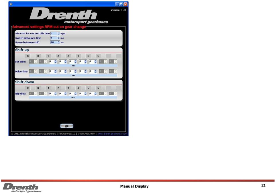
11 7. Advanced setting cut times With the box [Cut time] you can set the time that the relay is active. The time that is needed depends on the type of engine and ratio s in the gearbox. To reverse the signal that is going to the relay, you can select the box [Invert output]. You can determine whether the relay stays open or stays closed. The delay time is the time to wait for the cut time. Please leave the delay time set to nil as this is only used on recommendation of Drenth. The cut time is the time that the ignition is paused. To use the advanced settings, first select [Use advanced settings] (tick box) and then select [Advanced settings]. With the box [Min RPM for cut and blib time] you can set the minimum RPM that must be reached to provided an engine cut or throttle blip. With the box [Switch debounce time] you can set the minimum time that the switch in the gearbox needs to be activated for a useful signal. With the box [Pause between shift] you can set the time that you need to wait to shift for the next time. This will avoid accidentally shifting down or up several times short after each other. With the boxes [Blip time] you can set for several gears the time that the purple wire is switched to ground, for example for throttle blip. 11
 and then select [Advanced settings].")
12 12
13 8.Shiftlight In this box the shift light rpm and mode can be set. With the slide bar in this box it is possible to see a demo of the different modes in the display box. The 4 different modes available are: - Mode 0: On the set level the gear display will change to a completely filled flashing display. - Mode 1: On the set level the gear display will change to a completely filled display without flashing. - Mode 2: 900 rpm before the set level the display is emptied and will then be filled bottom row first, then upwards until the display is completely filled. - Mode 3: 900 rpm before the set level the display is emptied and will then be filled bottom row first, then upwards until the display is completely filled. The display is flashing when it s being filled upwards. 9. Output 2 In this box the function of the purple wire can be set. The different possibilities are: - Reverselight: The purple wire can be used for the reverse light - Blip: If this is selected the purple wire can be used for switching the throttle blip. - No function (high): The purple wire has no function. 13

14 10. Default If this button is used the software will load the file {default.drg} and delete the settings that are on your screen. 11. Automatic Cal. With this button the rotary sensor that is mounted in the gearbox can be calibrated. After pressing the button [Automatic Cal.] a dialog box will open and you will be asked to put it in reverse gear, at the same time the display will show a [p]. When the gear is selected click on the [ok] button. Repeat until the last gear is done. When you rebuild the gearbox it is recommended to check this first, because the position of the rotary sensor is difficult to change when the gearbox is mounted in the car. 14
![] a dialog box will open and you will be asked to put it in reverse gear, at the same time the display will show a [p].](/docs-images/40/11106763/images/page_14.jpg "When the gear is selected click on the [ok] button. Repeat until the last gear is done.")


15 12. Rotary sensor First make sure that the rotary sensor is mounted in the right position, on the ridge of the potentiometer there s a small notch. Make sure the ridge is standing vertical with the notch facing downwards and the cable needs to go up. Before mounting make sure the gearbox is in reverse. For a detailed graphic see figure below. When this message appears there are two things you need to check. When the voltage is not correct with the rotation direction you need to check the colour of the signal wire, see page 4 and 5. If the voltage starts at 2,5 Volts instead of starting at 0 Volts you need to turn the rotary sensor 180 degrees. 15

16 13. Manual Calibration With this function you can do the manual calibration. The values must increase otherwise the display will show an incorrect value. If the rotary sensor gives a voltage that is between two gear positions the display will show [x] to show you the gearbox is not properly engaged. You can measure the voltage from the rotary sensor on signal wire to determine right value. 16
![If the rotary sensor gives a voltage that is between two gear positions the display will show [x]](/docs-images/40/11106763/images/page_16.jpg "to show you the gearbox is not properly engaged.")
17 14. Display brightness With this function you can set the brightness of the display. The [automatic] selection only works on displays with a day light sensor, which is located on the front of the display. 15. Number of gear positions With the [on/off] setting you can set how many gear positions are used, it is important to set this correctly. The function [Automatic Cal.] uses these values to see how many gear positions there are, and if not set correctly [Automatic Cal.] it will not function. With [display text] you can set in which order and how many gears there are. 17
![Number of gear positions With the [on/off] setting you can set how many gear positions are used, it is important to set this correctly.](/docs-images/40/11106763/images/page_17.jpg "The function [Automatic Cal.] uses these values to see how many gear positions there are, and if not set correctly [Automatic Cal.")
18 Setting up for powershifting This is a brief description about adjusting the power shift system. If you make use of the switch you need to adjust it first. Then you can setup the cut time via the supplied software. Depending on the type of gearbox delivered from Drenth, there is an external switch mounted on the gearbox or Drenth can supply a strain gauge gearlever. This switch or gearlever detects an up shift. When an up shift is detected the controller cuts of the ignition by the programmed amount of time. External Switch The external switch comes preset from the factory. For the switch please check if it is set correctly. Use a multimeter to determine if the switch is closed. When you are up shifting the switch should close when all the play in the selection system is pushed out. You will feel an increase of force needed to pull the lever. This is when the switch should be closed. You can adjust it via the shims supplied with the power shift switch. Strain Gauge Gearlever The strain gauge gearlever comes preset from the factory. The gearlever has an analogue output, this output contains three wires (yellow, black and grey). Yellow contains 5 Volts, black contains ground and grey is the analogue readout. When the gearlever is in neutral position it sends out 2,5 Volts. By pulling the gearlever the voltage will increase and by pushing the gearlever the voltage will decrease. For more detailed information on the strain gauge gearlever please see the manual for the strain gauge gearlever. Test the RPM pickup Set the shift light to 2000 rpm mode 0. If it starts at a different rpm, the software may be set up incorrectly. If it does not work, there might not be a rpmsignal pickup. Please check all the connections and the pink / green wire like mentioned on page 4. Cut times We recommend that you drive the car first with no power shift and use the clutch with up- and downshifting. When you pull the gear lever make sure that you make a full stroke, pull convinced. Then try to shift up without use of the clutch and lift your foot off the throttle. Notice that the shifting with the gear lever should go just as easily as it would when using the clutch. First try to flat shift using the default values (cut time for each gear 100 ms). You will feel a difference when selecting gears. Some will feel like shifting with a clutch, but the most will feel stiffer or more harsh. After that there can be started with the fine tuning, notice that how higher the gear ratio how higher the shift times has to be. If you have achieved to find an optimum setting for the gear s 2 till 5, then we recommend to use advanced settings. Set the cut time for each gear independently at the recent found settings. Then lengthen the time for the lower gears, and shorten the time for the higher gears. The cut time will vary between ms. If it s too long or to short it won t shift with the same feeling as when using the clutch. Note that a properly setup power shift system, can reduce wear on the gearbox. Also a not very accurate setting can cause damage! Delay times The delay time is the time to wait for the cut time. Please leave the delay time set to nil as this is only used on recommendation from Drenth. 18

19 Contact Information Address Drenth Motorsport Gearboxes Fleuweweg AG Enter The Netherlands Phone: +31 (0) Fax: +31 (0) Contact Persons Sales department: Johan Drenth Engineering: Jeroen Grolleman 19


20 20

MAGICAR M870AS. Car alarm with two-way remote and remote - start system Installation guide
 MAGICAR M870AS Car alarm with two-way remote and remote - start system Installation guide EN English TABLE OF CONTENTS I. INTRODUCTION...4 II. PLACING...4 III. ADDITIONAL RELAY 12V CONNECTION...1 IV. WIRING
SECURITY SYSTEM ADP-CAN
 INSTALLATION INSTRUCTION SECURITY SYSTEM ADP-CAN Introduction Motorcar security system ADP-CAN is for motorcars provided with CAN net. It is for the work with the motorcar factory security systems or remote
Electronic Power Control
 Service. Self-Study Programme 210 Electronic Power Control Design and Function With the Electronic Power Control system, the throttle valve is actuated only by an electric motor. This eliminates the need
TOYOTA ELECTRONIC CONTROL TRANSMISSION
 Electronic Control Transmission (ECT) The Electronic Control Transmission is an automatic transmission which uses modern electronic control technologies to control the transmission. The transmission itself,
i ChatterBox! Motorcycle Security
 i Before you Start the Installation * Please read this manual to become familiar with the requirements necessary to complete the installation. * Use a high quality multi-meter to test all wires before
G-100/200 Operation & Installation
 G-100/200 Operation & Installation 2 Contents 7 Installation 15 Getting Started 16 GPS Mode Setup 18 Wheel Sensor Mode Setup 20 Fuel Calibration 23 Basic Operation 24 Telemetery Screen 27 Entering a Distance
PUSH BUTTON START INSTALLATION MANUAL
 PUSH BUTTON START INSTALLATION MANUAL ALTHOUGH THIS PRODUCT HAS BEEN THOROUGHLY TESTED KPIERSON TECHNOLOGIES ASSUMES NO RESPONSIBILITY FOR ANY DAMAGE THAT MAY RESULT BY THE INSTALLATION OF THIS PRODUCT.
Servo Info and Centering
 Info and Centering A servo is a mechanical motorized device that can be instructed to move the output shaft attached to a servo wheel or arm to a specified position. Inside the servo box is a DC motor
WIRING HARNESS FOR AS635P4. BLUE PLUG RED, BLUE, BLACK, WHITE - Plug in dual stage sensor harness
 WIRING HARNESS FOR AS635P4 ANTENNA NOT USED 5 PIN WHITE PLUG 2 PIN WHITE PLUG GREEN - PARKING BRAKE INPUT (-) BLUE - NOT USED 3 PIN BLUE PLUG RED, BLUE, BLACK, WHITE - Plug in dual stage sensor harness
Electronic Manual Gearbox
 Service. Self-Study Programme 221 Electronic Manual Gearbox Design and Function Taking the Lupo as the basis, Volkswagen has developed the world's first 3 L car that will also go into volume production.
INSTALLATION MANUAL 3RP / 5RP 4-BUTTON SERIES VEHICLE SECURITY SYSTEMS
 3RP / 5RP 4-BUTTON SERIES VEHICLE SECURITY SYSTEMS INSTALLATION MANUAL Before you begin the installation Read the INSTRUCTIONS! Always use a multi-meter when verifying vehicle wiring. Before mounting the
SHIFT INTERLOCK SYSTEM SHIFT INTERLOCK SYSTEM
 SHIFT INTERLOCK SYSTEM The shift lock system is designed to ensure the proper operation of the automatic transmission. The driver must depress the brake pedal in order to move the gear selector from Park
INSTRUMENT PANEL. 1995 Volvo 850 DESCRIPTION & OPERATION. 1995-96 ACCESSORIES & EQUIPMENT Volvo Instrument Panels
 INSTRUMENT PANEL 1995 Volvo 850 1995-96 ACCESSORIES & EQUIPMENT Volvo Instrument Panels 850 WARNING: When working around steering column and before performing repairs, disconnect and shield battery ground
VEHICLE SPEED CONTROL SYSTEM
 PL VEHICLE SPEED CONTROL SYSTEM 8H - 1 VEHICLE SPEED CONTROL SYSTEM TABLE OF CONTENTS page DESCRIPTION AND SPEED CONTROL SYSTEM...1 SPEED CONTROL SERVO-PCM OUTPUT....2 SPEED CONTROL SWITCHES PCM INPUT...2
Button 1 Button 2. Button 3 Button 4. Programmed Remote Transmitter. Button Function Condition
 WWW.STELLAR.COM ST9000 SECURITY SYSTEM Button Function Condition 1 a. Arm and lock doors b. Car finder with sound c. Temporary stop alarm from sounding d. Remote lock doors 1 for 2 sec. Panic Anytime a.
TOYOTA ELECTRONIC TRANSMISSION CHECKS & DIAGNOSIS
 Checks and Adjustments The transmission requires regular maintenance intervals if it is to continue to operate without failure. As we discussed in previous sections, transmission fluid loses certain properties
How To Control A Car Alarm On A Car With A Remote Control System
 MODEL CA100 REMOTE CONTROL AUTO ALARM SYSTEM INSTALLATION & OPERATION INSTRUCTIONS WIRING DIAGRAM Black Antenna Wire 6 Pin 6 Pin Mini Connector Valet Switch Blue LED Indicator Blue Wire: (-) 200mA Unlock
GEARBOX MONITOR MODEL NR. 1.1203 USER MANUAL
 GEARBOX MONITOR MODEL NR. 1.1203 USER MANUAL USER SAFETY Before starting to drive with a mounted gearbox monitor you need to make sure that: the monitor does not limit field of vision of the driver; monitor
Electrical Systems - IQAN Digital Control System. IQAN Control System Components... 5.1.3
 Section 5.1 Electrical Systems - IQAN Digital Control System IQAN Control System Components........................... 5.1.3 IQAN Operational Description: At Machine Startup.....................................
AMS-1000 Multi-Channel Air Management System for Boost Control
 AMS-000 Multi-Channel Air Management System for Boost Control The terminal pin descriptions may also be viewed on screen. See Page 4 of manual for details. Clutch Input Shift Input Scramble Boost Input
POWER TRIM 5 F AUTO TRIM AND AUTO TRIM
 POWER TRIM 5 F 22217 AUTO TRIM AND AUTO TRIM Table of Contents Page Auto Trim System........................ 5F-1 Description........................... 5F-1 Auto Trim Operation...................... 5F-2
INSTALLATION GUIDE. www.security.soundstream.com FCC ID NOTICE
 AL.1 AUTO SECURITY SYSTEM INSTALLATION GUIDE www.security.soundstream.com FCC ID NOTICE This device complies with Part 15 of the FCC rules. Operation is subject to the following conditions: 1. This device
Left Hand Limit Switch. Housing. Left Hand. Connections. Motor Connector BROWN PURPLE GRAY BLACK DARK BLUE BLACK BROWN BROWN LIGHT BLUE.
 LIGHT BLUE GRAY PURPLE Circuit Breaker Intput Circuit Breaker Output #1 Relay Left Hand Limit Switch Housing Left Hand Motor Connector Right Hand Limit Switch on Radiator Support Right Hand Limit Switch
Operating instructions Diffuse reflection sensor. OJ50xx 701396 / 01 07 / 2004
 Operating instructions Diffuse reflection sensor OJ50xx 7096 / 0 07 / 004 Contents Preliminary note. Symbols used Function and features Installation. Installation of the supplied mounting fixture 4 4 Electrical
Firmware version: 1.10 Issue: 7 AUTODIALER GD30.2. Instruction Manual
 Firmware version: 1.10 Issue: 7 AUTODIALER GD30.2 Instruction Manual Firmware version: 2.0.1 Issue: 0.6 Version of the GPRS transmitters configurator: 1.3.6.3 Date of issue: 07.03.2012 TABLE OF CONTENTS
Juice Box Stages 1&2 135&335 Installation Guide 5/10/08
 Tools Required: 8mm socket or nut driver Small flat head screwdriver Electrical tape, masking tape, or shrink tube Pep talk: Although the install looks daunting at first, once you get the learning curve
USER MANUAL OPERATION AND USE OF CAR WITH. Diego G3 / NEVO SEQUENTIAL GAS INJECTION SYSTEM
 USER MANUAL OPERATION AND USE OF CAR WITH Diego G3 / NEVO SEQUENTIAL GAS INJECTION SYSTEM Page 2 z 7 Table of contents 1. STARTING THE ENGINE... 3 2. CONTROL PANEL... 3 2.1 Indication of the current level
Multi Function, User Configurable Remote Vehicle Security System with 4 Button Replaceable Membrane Remote Transmitter
 MODEL PRO-9744 INSTALLATION MANUAL Multi Function, User Configurable Remote Vehicle Security System with 4 Button Replaceable Membrane Remote Transmitter This System Allows The Transmitter Buttons To Be
INSTALLATION MANUAL VEHICLE SECURITY SYSTEM CE-SS200
 INSTALLATION MANUAL VEHICLE SECURITY SYSTEM CE-SS200 FUSION CULTURE TABLE OF CONTENTS There s no point doing something if no one notices. We ve always believed the way to make things happen is by getting
Diagnosing and Understanding Starting Problems on the ZR-1 Marc Haibeck 28-Sep-13
 Diagnosing and Understanding Starting Problems on the ZR-1 Marc Haibeck 28-Sep-13 There are three basic failure conditions: - A VATS security system lockout - A click from the starter solenoid but no engine
1115 4G SERIES GOVERNOR. 4-20 ma ANALOGUE DIGITAL SPEED SETTING
 1115 4G SERIES GOVERNOR with 4-20 ma ANALOGUE & DIGITAL SPEED SETTING PO Box 28, 9300AA Roden, The Netherlands Tel: +31 505019888 Fax: +31 505013618 E-mail: regulateurs@regulateurs-europa.com 1115 4G
Switch Actuator, 8-fold, 10 A, MDRC AT/S 8.10.1, GH Q631 0075 R0111
 , GH Q631 0075 R0111 The 8-fold switch actuator is a DIN rail mounted device for insertion in the distribution board. It is connected to the EIB via a bus terminal. In the event of bus voltage failure,
AUTODIALLER / QUICKDIALLER - SA132
 AUTODIALLER / QUICKDIALLER - SA132 INSTRUCTION LEAFLET ENGLISH www.thermomax-group.com CONTENTS 1 SETUP AT A GLANCE... 2 2 FOREWORD....... 3 3 INSTALLATION...... 4 4 KEYPAD AND INDICATORS...... 5 SETTING
Parts List. Navigation
 Parts List quantity description 1 LCD-200 Display 1 LCD-200 Display cable 1 CD-ROM 2 dual lock or velcro 1 1GB SD card (optional) 1 CAN termination plug Navigation Main Menu Begin Log/Stop Log page 4 Log
How to read this guide
 How to read this guide The following shows the symbols used in this Quick start guide with descriptions and examples. Symbol Description Example P oint Reference Caution [ ] This symbol explains information
MotorCycle Alarm by DEF COM 3 INSTALLATION MANUAL 80 C
 DEF COM 3 INSTALLATI MANUAL MotorCycle Alarm by IMMOBILISER (FAIL SAFE SYSTEM) Positive Logic (the relay switches over when the central unit is disarmed and ignition +15 is present.) Fig.2 Fig.3 SUPPLEMTARY
PRODUCTIVITY THROUGH INNOVATION 600 CONTROL DIRECT DRIVE TECHNICAL/OPERATION MANUAL
 Rev. D PRODUCTIVITY THROUGH INNOVATION 600 CONTROL DIRECT DRIVE TECHNICAL/OPERATION MANUAL 10 BORIGHT AVENUE, KENILWORTH NEW JERSEY 07033 TELEPHONE: 800-524-0273 FAX: 908-686-9317 TABLE OF CONTENTS Page
Stop Alert Flasher with G-Force sensor
 Stop Alert Flasher with G-Force sensor Stop Alert module creates brake light flashing effect to catch attention of the drivers behind to avoid dangerous rear end collision. The flasher module is a state
The Child Reminder System Installation Manual
 The Child Reminder System Installation Manual Revised June, 2006 Detailed installation information can be found at www.childreminder.com. Get through your installation quickly and easily by calling 1-888-330-6786
Lectric Enterprises 5905 Sprucepine Drive Winston Salem, NC. 27105 Telephone 336-655-4801 e-mail: ivirscar@knight-f2k4.com
 KNIGHT RIDER DASH ELECTRONICS PILOT\SEASON 2-2 TV DASH INSTALLATION INSTRUCTION MANUAL Bezel Overlay Voice Box Instructions Relay connection for a dash startup delay. Connect to the +12v side of relay
ezsystem elab16m Project 1F: Alarm System (Full Project description)
") ezsystem elab16m Project 1F: Alarm System (Full Project description) ezsystem The aim of ezsystem is to enable Creativity and Innovation at an early age in a Problem Based Learning (PBL) approach. ezsystem
ezsystem elab16m Project 1F: Alarm System (Full Project description) ezsystem The aim of ezsystem is to enable Creativity and Innovation at an early age in a Problem Based Learning (PBL) approach. ezsystem
AUTOMATIC TRANSMISSION IN-CAR DIAGNOSTICS
 Learning Guide CHASSIS ELECTRICAL SPECIALIST AUTOMATIC TRANSMISSION IN-CAR DIAGNOSTICS COURSE NUMBER: C050-01 Notice Due to the wide range of vehicles makes and models, the information given during the
Product and functional description
 Product and functional description The KNX / DALI gateway N 141/02 is a 4 MU wide, DINrail mounted KNX device with one DALI interface to which up to 64 DALI actuators (e.g. DALI ballasts) can be connected
CR9971 2 Band Auto Set Dual Alarm Clock Radio ROBERTS. Sound for Generations. Please read this manual before use
 ROBERTS Sound for Generations CR9971 2 Band Auto Set Dual Alarm Clock Radio Please read this manual before use Contents Contents... 1 Controls...2-5 Switching on... 6 Setting the time manually... 6 Setting
WE-350 Series ¼ Turn Electric Actuator
 WE-350 Series ¼ Turn Electric Actuator Operation and Installation Manual Pg 1 (Rev. 020113) Table of Contents 1.0 General 1.1 Pre-Installation Inspection 1.2 Storage 1.3 Features & General Information
PRO PLM Installation Instructions
 PRO PLM Installation Instructions PROFESSIONAL INSTALLATION STRONGLY RECOMMENDED Installation Precautions: Roll down window to avoid locking keys in vehicle during installation Avoid mounting components
QUICK TUNE EFI INSTRUCTION MANUAL
 QUICK TUNE EFI INSTRUCTION MANUAL Step 1: Loading the CB quick Tune Software to your PC A) Take the CB Quick Tune installation CD and load it into your PC. A window will pop up asking to have all programs
SIT Sports. Safety Tracking System Manual WRC 2015
 SIT Sports Safety Tracking System WRC 2015 V2 1 SIT Sports Tracking Unit The SIT Sports Tracking unit must be fitted and connected in all competitors cars before arrival at scrutineering, where it will
Vario Tractors - Fault Codes. Faults. all Vario tractors Tractor / General system. EDC / EMR bus fault. Fault in ECU Programming errors in ECU.
 12/1999 f 1/58 Vario Tractors - Codes 0000 000001 Date Version Page Capitel Index Docu-No. FCT_InitPage 0.0.11 A021; A022 Id rief description Description Consequences Link FENDIAS / Note ECU, EDC; ECU,
Hybrid System Overview
 1 Hybrid System Overview January 31, 2004 2 Chevrolet Silverado / GMC Sierra Models: Extended Cab Short Box, 2WD & 4WD Engine: VORTEC 5.3 Liter V-8 Transmission: 4-speed auto transmission Power: 295 hp
Automotive Sensor Simulator. Automotive sensor simulator. Operating manual. AutoSim
 Automotive sensor simulator Operating manual AutoSim Contents Introduction.. page 3 Technical specifications.... page 4 Typical application of AutoSim simulator..... page 4 Device appearance... page 5
Inwall 4 Input / 4 Output Module
 Inwall 4 Input / 4 Output Module IO44C02KNX Product Handbook Product: Inwall 4 Input / 4 Output Module Order Code: IO44C02KNX 1/27 INDEX 1. General Introduction... 3 2. Technical data... 3 2.1 Wiring Diagram...
ANTI-THEFT SYSTEM. 1995 Volvo 850 DESCRIPTION & OPERATION BASIC ALARM. 1995-96 ACCESSORIES & EQUIPMENT Volvo Anti-Theft Systems
 ANTI-THEFT SYSTEM 1995 Volvo 850 1995-96 ACCESSORIES & EQUIPMENT Volvo Anti-Theft Systems 850 DESCRIPTION & OPERATION WARNING: Deactivate air bag system before performing any service operation. For 1995
Automatic Telephone Dialer TD-101(W)
") Automatic Telephone Dialer TD-101(W) The TD-101 is an automatic dialing device which can transmit prerecorded information via the telephone line. The dialer can send two different 10 second voice messages
Automatic Telephone Dialer TD-101(W) The TD-101 is an automatic dialing device which can transmit prerecorded information via the telephone line. The dialer can send two different 10 second voice messages
Wespot. SecNurse A NEW GENERATION TECHNICAL AIDS USER S GUIDE
 Wespot SecNurse A NEW GENERATION TECHNICAL AIDS USER S GUIDE EN This manual is published by OPTEX, without any warranty. Improvements and changes to this manual necessitated by typographical errors, inaccuracies
P10 - Standalone Access Controller and Reader
 www.quantek.co.uk T: 01246 417113 P10 - Standalone Access Controller and Reader 1 Description & Features: P10 is a waterproof standalone access control, reading EM&HID card, it uses advanced Microprocessor,
ECU MS 3 Sport GT3 Cup. Quick Start Manual
 ECU MS 3 Sport GT3 Cup Quick Start Manual V1.0 11/6/2015 Table of Contents Table of Contents 1 Welcome... 3 1.1 Hardware Checklist... 3 1.2 Hardware Installation... 3 1.3 Software Installation... 3 2 Tools:
PC SERIAL INTERFACE FOR LAMBDA GAS CONTROL LGC-700
 PC SERIAL INTERFACE FOR LAMBDA GAS CONTROL LGC-700 INDEX 1- Introduction 2- AGI-PRO Program Set-up 3- AGI-PRO Program Use 3.1- Interface Link 3.2- How Start AGI-PRO program 3.2-1. Page MONITOR 3.2-2. Page
Installation instructions for VW Golf VII & Skoda Octavia III all models 2013 > Signals on CAN: Brake - Clutch - VSS
 EL-PAS -Cruise II Installation instructions for VW Golf VII & Skoda Octavia III all models 2013 > Signals on CAN: Brake - Clutch - VSS e-cruise www.lpdk.com LP Lindgaard Pedersen A/S Page 1 / 5 Before
M.S Ramaiah School of Advanced Studies - Bangalore. On completion of this session, the delegate will understand and be able to appriciate:
 Transmission Control Lecture delivered by: Prof. Ashok C.Meti MSRSAS-Bangalore 1 Session Objectives On completion of this session, the delegate will understand and be able to appriciate: Rl Role of electronic
Contents Installing the ucal Software on your PC/Laptop ucal Programmer Version Connecting the ucal Programmer to your PC/Laptop
 Contents Installing the ucal Software on your PC/Laptop 1 ucal Programmer Version 1 Connecting the ucal Programmer to your PC/Laptop 1 Optional USB Adapter Kit (for ucal) 1 Installing the USB Driver for
 ABLOY DA60 SWING DOOR OPERATOR Installation and commissioning manual Abloy Oy An ASSA ABLOY Group company APPROVALS / STANDARDS Low Voltage directive 7//EEC as amended by the directive 9/68/EEC EMC directive
Manual IB-3620 Series
 IB-RD3620SU3 1 IB-3620U3 CONTENT 1. Introduction... 3 1.1 General Information... 3 2. Hardware IB-3620 Series... 4 2.1 LED Indication / Button Front Panel... 4 2.2 Rear View... 5 3. HDD Installation...
Mobile Satellite Solutions. A WiWorld Partner SATELLITE TV ANTENNA CONTROLLER RFM-1000/1100 TECHNICAL MANUAL STOW SEARCH
 Mobile Satellite Solutions A WiWorld Partner SATELLITE TV ANTENNA CONTROLLER RFM-1000/1100 TECHNICAL MANUAL SEARCH STOW Ver. 1 June 2012 WARNING Make all electrical and coax connections from the controller
ATL Fuel Level Sender Probes
 T E C H N I C A L S P E C I F I C A T I O N The ATL EL-AD-151 (Resistance Output) and EL-AD-152 (Voltage Output) Fuel Level Senders are highly advanced sensors for continuously measuring the contents of
Kelly KBS-L Brushless Motor Controller User s Manual
 Kelly KBS-L Brushless Motor Controller User s Manual Devices Supported: KBS24051L KBS24101L KBS24121L KBS36051L KBS36101L KBS48051L KBS48101L KBS48121L KBS72051L KBS72101L KBS72121L Rev.4.1 Jan. 2014 Chapter
Movement/monitoring 1307/1.0 (6325xx)
") /monitoring 1307/1.0 (6325xx) General In the following the device will be referred to as the movement detector. The movement block will only switch off when there is no more movement in front of the device
/monitoring 1307/1.0 (6325xx) General In the following the device will be referred to as the movement detector. The movement block will only switch off when there is no more movement in front of the device
Operating instructions Optical distance sensor O1D100 O1D103 704991 / 00 08 / 2012
 Operating instructions Optical distance sensor UK O1D100 O1D103 704991 / 00 08 / 2012 Contents 1 Preliminary note4 1.1 Symbols used 4 1.2 Warning signs used 4 2 Safety instructions 4 3 Functions and features
X8Pro Remote Control
 X8Pro Remote Control MID:COM X8PRO 8 CHANNEL FULLY PROPORTIONAL REMOTE CONTROL USER S GUIDE REVISED FOR SERIAL #1050 AND ABOVE MID:COM 1605 170 th Street Hampton, IA 504418 641-456-4848 641-456-4600 fax
MODELS 8007 Gorilla Cycle Alarm 8017 Gorilla Cycle Alarm with 2-way pager system 1018 2-way pager system
 MODELS 8007 Gorilla Cycle Alarm 8017 Gorilla Cycle Alarm with 2-way pager system 1018 2-way pager system Remote Control Motorcycle Alarm System Installation & Operation Instructions Sistema de Alarma de
CurveMaker v2.1 DYNAFS programmable ignition software
 CurveMaker v2.1 DYNAFS programmable ignition software Dynatek 164 S Valencia St. Glendora CA 91741 phone (626)963-1669 fax (626)963-7399 Contents 1) Installation...1 2) Overview...1 3) Programming a Curve...4
www.sebury.com.cn Digital Keypad Use s Manual
 K3 K4 www.sebury.com.cn Digital Keypad Use s Manual Contents Introduction Introduction Specifications Intramural Interface Circuit 3 Mounting 3 Wiring 5 Power UP 7 Engineer Programming Mode 7 The K3/K4
535T Window Automation System
 535T Window Automation System Installation Guide NOTE: This product is intended for installation by a professional installer only! Any attempt to install this product by any person other than a trained
POINTS POSITION INDICATOR PPI4
 POINTS POSITION INDICATOR PPI4 Advanced PPI with Adjustable Brightness & Simplified Wiring Monitors the brief positive operating voltage across points motors when they are switched Lights a corresponding
Electronic Pressure Switch EDS 3000
 For Your Information Electronic Pressure Switch EDS 3000 User Manual Revision: November 01, 2002 1. EDS 3000 Functions The EDS 3000 unit offers the following functions: Display pressure in psi, MPa, or
VEHICLE SECURITY SYSTEM G25/G20
 VEHICLE SECURITY SYSTEM G25/G20 Limited Lifetime Warranty This vehicle security system is warranted to the original purchaser, to be free from defects in material and workmanship. The manufacturer will
B/S/H/ Error codes and service programmes PH
 1 ERROR CODES AND APPLIANCE MESSAGES... 3 1.1 Complete overview of all error codes (in order)... 3 Automatic switch-off... 3 Display is dark and any individual LEDs are lit... 3 E 005... 3 E 011... 3 E
Unit 24: Applications of Pneumatics and Hydraulics
 Unit 24: Applications of Pneumatics and Hydraulics Unit code: J/601/1496 QCF level: 4 Credit value: 15 OUTCOME 2 TUTORIAL 4 DIRECTIONAL CONTROL VALVES The material needed for outcome 2 is very extensive
MODEL 5010 DUAL CHANNEL SMOKE/FIRE DETECTION MODULE
 DESCRIPTION MODEL 5010 DUAL CHANNEL SMOKE/FIRE DETECTION MODULE DESCRIPTION The SST Model 5010 Two Channel Smoke/Fire Detection Module provides two independent detection input channels for the NOVA-5000
MAGICAR M871A. Car alarm with two-way remote User s guide
 MAGICAR M871A Car alarm with two-way remote User s guide EN MAGICAR M871A Car alarm with two-way remote User s guide TABLE OF CONTENTS Table of contents...2 1. Important notice...4 2. Introduction...4
AUTOMATIC TRANSFER SWITCH CONTROL UNIT OPERATOR S MANUAL
 ATS-220 AUTOMATIC TRANSFER SWITCH CONTROL UNIT OPERATOR S MANUAL For Use in 208 to 240 Volts Single and 3 Phase ATS Systems With 110Volt AC or DC Control Motors and selenoids 4501 NW 27 ave Miami FL 33142
Installation Guide for Hive Active Heating
 Installation Guide for Hive Active Heating Important note: Installation should only ever be carried out by a qualified engineer. Technical Support If you need to contact Hive s Technical Support team during
RF Etch Monitor. Introduction
 RF Etch Monitor Introduction A newly designed RF Matching Controller & RF Etch Monitor replaces the old OEM design of the RF Matching Controller and the RF Etch Monitor. OEM RF Matching Controller: - Analog
Electrical data Nominal voltage AC/DC 24 V Nominal voltage frequency
 echnical data sheet NV24A--RE Communicative globe valve actuator for 2-way and 3-way globe valves Actuating force 1000 N Nominal voltage AC/DC 24 V Control Modulating DC (0)2...10 V Variable Nominal stroke
BLOCK OCCUPANCY DETECTOR WITH SEMAPHORE OPERATION BOD1/DAP4-BR
 BLOCK OCCUPANCY DETECTOR WITH SEMAPHORE OPERATION BOD1/DAP4-BR This Block Occupancy Detector recognises the current drawn by moving trains within a block, and can operate a number of built-in programs
Contactless Encoder RI360P0-QR24M0-INCRX2-H1181
 Compact, rugged housing Many mounting possibilities Status displayed via LED Immune to electromagnetic interference 1024 pulses per revolution (default) 360, 512, 1000, 1024, 2048, 2500, 3600, 4096, parametr.
Heat Surge Model X5C Fire Place Insert Service Manual Applies to all units w/30000208 circuit board
 Heat Surge Model X5C Fire Place Insert Service Manual Applies to all units w/30000208 circuit board 2012 HS M4417A BR16597R-1 HEAT SURGE 8000 FREEDOM AVE, N. CANTON, OH 44720 330-244-8161 WWW.HEATSURGE.COM
Security and Remote Start Installation Guide for models: CA 6150 CA 6550
 PROFESSIONAL SERIES Security and Remote Start Installation Guide for models: CA 6150 CA 6550 2009 Audiovox Electronics Corporation. All rights reserved. 1 Table of Contents Before You Begin... 4 Wire Connection
LAND ROVER MANUAL CONTENTS APPLICATIONS GENERAL OPERATION SPECIAL FUNCTIONS REMOTE CONTROL PROGRAMMING
 LAND ROVER LAND ROVER MANUAL CONTENTS APPLICATIONS GENERAL OPERATION SPECIAL FUNCTIONS REMOTE CONTROL PROGRAMMING APPLICATIONS VEHICLE SYSTEM YEAR CABLE CLASSIC RANGE ROVER 10AS 95 ON ADC110-B DEFENDER
HYDRA HV OPERATION MANUAL. 2.0 Making Connections on your HYDRA speed control. Rosin core electrical solder
 HYDRA HV OPERATION MANUAL Starting Power Safe power on arming program helps prevent motor from accidentally turning on. Always use extreme care with high power systems. Auto shut down when signal is lost
PATENTED: www.voxxintl.com/company/patents
 Model PRO9776C Installation Manual Vehicle Security System Table Of Contents: with Remote Start Before You Begin Page 2 Wire Harnesses Quick View Page 3-4 Installation of the Major Components Page 5 Wiring
Renewable Energy Monitor User Manual And Software Reference Guide. sales@fuelcellstore.com (979) 703-1925
 703-1925") Renewable Energy Monitor User Manual And Software Reference Guide sales@fuelcellstore.com (979) 703-1925 1 Introducing the Horizon Renewable Energy Monitor The Renewable Energy Monitor is an educational
Renewable Energy Monitor User Manual And Software Reference Guide sales@fuelcellstore.com (979) 703-1925 1 Introducing the Horizon Renewable Energy Monitor The Renewable Energy Monitor is an educational
QUICK START GUIDE 199R10546
 QUICK START GUIDE 199R10546 1.0 Overview This contains detailed information on how to use Holley EFI software and perform tuning that is included within the software itself. Once you load the software,
ibidi PumpControl Instruction Manual Version 1.5.2
 ibidi PumpControl Instruction Manual Version 1.5.2 ibidi PumpControl instructions II ibidi GmbH 2016, Version 1.5.2, 04 May 2016 Table of contents 1. General Information... 3 1.1 System Requirements...3
HERZ-Thermal Actuators
 HERZ-Thermal Actuators Data Sheet 7708-7990, Issue 1011 Dimensions in mm 1 7710 00 1 7710 01 1 7711 18 1 7710 80 1 7710 81 1 7711 80 1 7711 81 1 7990 00 1 7980 00 1 7708 11 1 7708 10 1 7708 23 1 7709 01
Phoenixtech Brushless Motor Speed Controller Programming Guide
 Congratulations on the purchase of your new Phoenixtech Brushless Motor Speed Controller. This latest series of controllers is unique in that it is equipped with a robust internal switching Battery Eliminator
AUTO TRANS DIAGNOSIS Article Text 1998 Volkswagen Passat This file passed thru Volkswagen Technical Site - http://volkswagen.msk.
 AUTO TRANS DIAGNOSIS Article Text 1998 Volkswagen Passat This file passed thru Volkswagen Technical Site - http://volkswagen.msk.ru ARTICLE BEGINNING 1997-98 AUTOMATIC TRANSMISSIONS Volkswagen Shift Interlock
RECOMMENDED TOOLS PERSONAL & VEHICLE PROTECTION SAFETY GLASSES
 HYUNDAI ACCENT 2010- /ELANTRA 2012- / KIA RIO 2012- PART NUMBER: 250-9628 GENERAL APPLICABILITY THIS CRUISE WAS TESTED AND VERIFIED ON: (AT/MT) VEHICLES RECOMMENDED TOOLS PERSONAL & VEHICLE PROTECTION
SMS Alarm Messenger. Setup Software Guide. SMSPro_Setup. Revision 090210 [Version 2.2]
![SMS Alarm Messenger. Setup Software Guide. SMSPro_Setup. Revision 090210 [Version 2.2]](/thumbs/29/13662687.jpg "SMS Alarm Messenger. Setup Software Guide. SMSPro_Setup. Revision 090210 [Version 2.2]") SMS Alarm Messenger SMSPro_Setup Revision 090210 [Version 2.2] ~ 1 ~ Contents 1. How to setup SMS Alarm Messenger?... 3 2. Install the SMSPro_Setup software... 5 3. Connection Type... 6 4. Connection Port
SMS Alarm Messenger SMSPro_Setup Revision 090210 [Version 2.2] ~ 1 ~ Contents 1. How to setup SMS Alarm Messenger?... 3 2. Install the SMSPro_Setup software... 5 3. Connection Type... 6 4. Connection Port
MXG Dash Logger USER GUIDE
 Dash Logger USER GUIDE AiM Srl. Via Cavalcanti, 8 20063 Cernusco S/N (MI) Italia Tel. (+39) 02.9290571 Made in Italy www.aim-sportline.com Dash Logger 04 06 08 10 11 12 12 12 14 16 17 18 19 21 22 23 23