Inverter / Charger Installation General Operations and AC and DC Connections
|
|
|
- Horatio McDonald
- 10 years ago
- Views:
Transcription
1 Inverter / Charger Installation General Operations and AC and DC Connections

2 The Inverter is just one piece. Sometimes, a tendency is to mount the inverter and batteries, and make it work It is better if we pay attention to the other practices that make a good, reliable installation.

3 Elements of the Inverter / Charger

4 Elements of the Inverter / Charger DC to AC Inverter; AC to DC Battery Charger; Transfer Switch between using AC Incoming Power or Battery Power; Transfer Switch to choose between two different AC Sources; Relays to perform a variety of user selected functions; and Computer with LCD screen and user input for customizing most of the variables.

5 Applicability This presentation is based on the Xantrex Model SW inverter, observed most frequently during field visits, and is applicable to models SW 4048 and SW 5548, which were most prevalent. With minor variations, this information can be applied to Outback Power equipment and other manufacturers equipment.

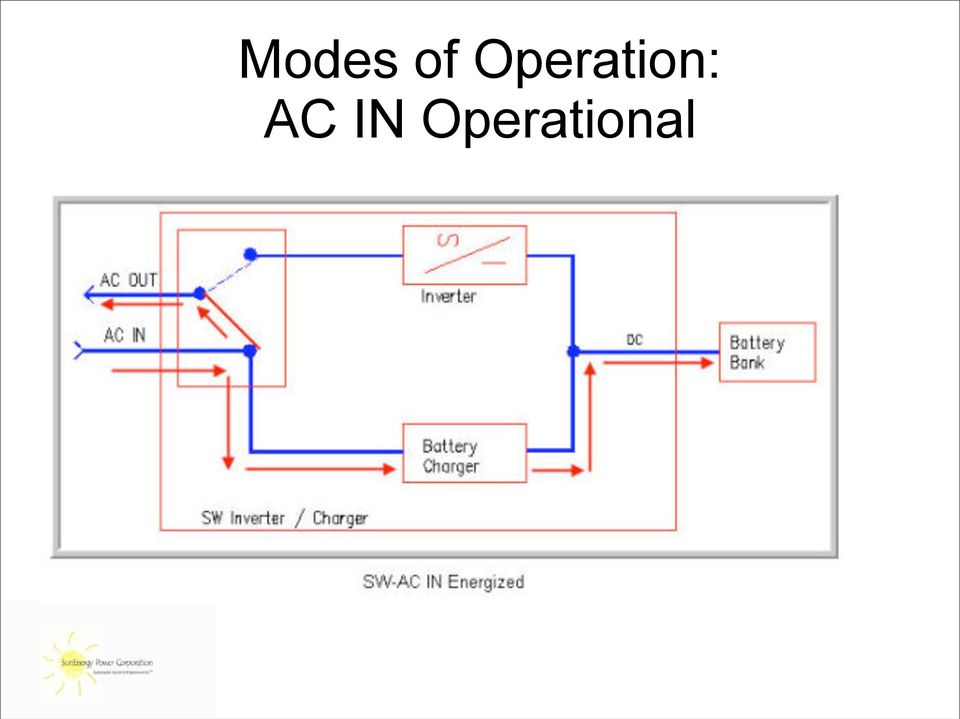
6 Modes of Operation: AC IN Operational The SW can be connected into an electrical scheme in many different ways. However, some common elements remain unchanged from installation to installation. The over-riding purpose of the SW is to provide continuous power to the loads (AC OUT). If there is power (with the proper characteristics) at the AC IN terminals, then the equipment will utilize this power to: Power the Loads (AC OUT); and Charge the Batteries through the built-in Battery Charger. The following diagram shows the operation and power flow when there is proper power supply at the AC IN terminals:
 at the AC IN terminals, then the equipment will utilize this power to: Power the Loads (AC OUT);")
7 Modes of Operation: AC IN Operational
8 Operation: When AC IN Power is lost When power is lost to AC IN, the on-board computer switches the transfer switch so that the AC OUT loads are fed from the battery through the DC to AC Inverter, and the inverter is turned on. This happens nearly instantaneously. When this situation occurs, the entire load is powered by the battery bank. Of course, this can not go on forever, and when the battery bank reaches a programmed low state of charge (depicted by low voltage) the system turns off. (Alarms can be installed to warn operators of impending cut-out, see section 10.2)
 the system")
9 Modes of Operation: AC IN Operational

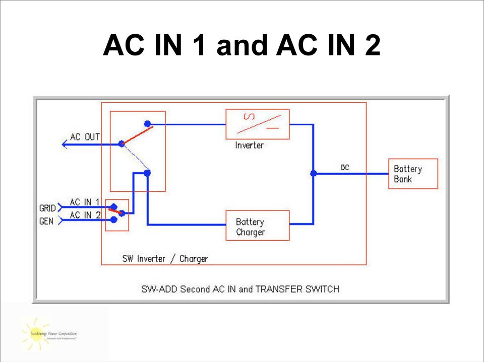
10 AC IN 1 and AC IN 2 The SW model inverter/charger includes provisions for two AC Inputs. Field visits did not reveal any field application where both inputs were used. In many cases, both inputs will not be needed, but there are many applications where they would be useful. The basic system diagram changes only at the AC IN provisions:

11 AC IN 1 and AC IN 2
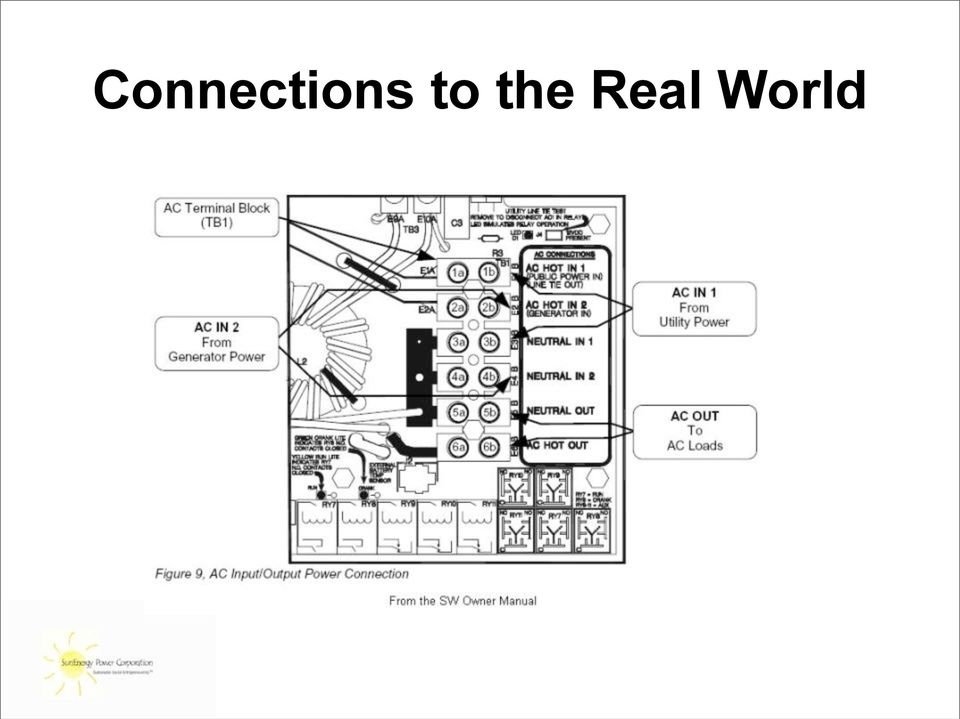
12 Connections to the Real World The SW equipment is strictly the core equipment necessary to monitor and switch power sources to feed the given load. In order to become part of the entire wiring system, it is essential to use proper wire sizes, and the proper fusing and disconnecting means to (a) protect the wiring, (b) protect the equipment, and (c) protect people. In many cases, when improper auxiliary equipment is used (or not used at all) not only is the result unsafe, but it also results in improper operation, battery failure and un-powered loads. These problems can be avoided by following some guidelines on connecting the SW equipment to the rest of the electrical system. In the next section, the manual will discuss AC OUT connections, AC IN connections, and finally DC and battery connections.
 not only is the result unsafe, but it also results in improper operation, battery failure and un-powered loads.")
13 Connections to the Real World
14 AC OUT Connections All of the AC terminal blocks inside the SW AC box (on the left hand side of the unit) will accept up to #6 AWG conductors (16mm2). It is advised that this #6, 10mm2, or 16mm2 wire be used. The AC OUT terminals should be supplying only a predetermined set of loads. These loads should have been the basis of the selection of the size of the battery bank and the size of the inverter. These loads should be fed from a separate, dedicated circuit breaker panelboard connected to the AC OUT terminals. The conductors carrying the load current from the SW to this panelboard should land first in either a fused disconnect switch, or a main circuit breaker on the panelboard.

15 AC OUT Connections

16 AC IN Connections There are several options for AC IN connections: AC IN from a grid supply only AC IN from a generator supply only AC IN from both a grid supply and a generator supply AC IN from a combined grid / generator supply. The following section discusses each option.

17 AC IN 1 Grid Supply
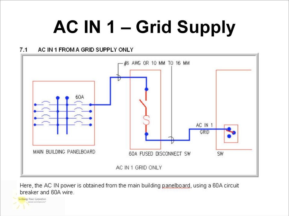
18 AC IN 1 Grid Supply Even though the output of the inverter is limited to either 33 or 46 amps, it is important that the 60 amp circuit breaker is used and conductors feed the AC IN terminals. This is because when the grid power is on, it is performing two functions: First it is feeding the loads, and secondly it is powering the battery charger. The battery charger could draw up to as much as 30 amps depending on how the settings are programmed. If it is not possible to provide a 60 amp supply to the ACIN 1 terminals of the SW, then certain settings MUST be changed in the programming, and the design needs to be studied to be sure that the batteries will receive enough charging power. See the discussion under Programming for more information on this subject.

19 AC IN 1 Grid Supply

20 AC IN 2 - Generator

21 AC IN 2 - Generator The amount of power that can be drawn from the generator needs to be calculated (based on the size of the generator and other loads the generator may have to supply). If, for example, a 6KW generator is dedicated to this inverter, then the maximum power that can be obtained from the 6KW generator (if it is single phase) is 6000w / 120V or 50Amps. In this case, a 40 amp breaker to feed the SW and a therefore, 40A wire will be sufficient. If the generator is designed to support other loads as well, then how much of its power can be dedicated to the SW equipment needs to be determined and the breaker and conductors needs to be sized accordingly. The proper programming needs to be completed to match this value. The equipment needs to be programmed so that it does not try to pull any more power than the circuit breaker feeding it (or any more power than the generator feeding it.). This would trip the breaker and/or overload the generator. See the section on Programming for more information.
22 AC IN from both Generator and Grid
23 AC IN from both Generator and Grid When both grid power supply and generator power supply are available, the above is the preferred method for connecting to the system, particularly when the generator size requires a smaller circuit breaker and feeder that would be allowed by the grid input power. However, in most cases with grid and generator available, the two sources are combined in a transfer switch, with one set of conductors going into the SW, as shown below.
24 AC IN from both Generator and Grid
25 AC IN from both Generator and Grid Discuss pros and cons of the combined Generator / Grid AC IN wiring versus the separate Generator and Grid AC wiring.
26 AC IN and OUT Connections Summary of AC IN and AC OUT Connections There are several different configurations possible for the AC IN and AC OUT connections. Key factors to consider in planning the installation are: Sizing of the conductors for the greatest possible current that they may experience; Using dedicated, separate, AC OUT circuit breaker panelboards for the loads decided to be powered by the SW; Bringing separate AC IN 1 Grid conductors and AC IN 2 Gen conductors to the SW equipment panel; and Providing disconnecting means for the ACIN 1, AC IN 2, and AC OUT conductors to be able to isolate the SW equipment from any power wires. Additionally, the SW Cabinet should be installed in a readily accessible location (not in a storeroom), where ventilation from left to right is unobstructed, to provide adequate cooling.
27 AC IN and OUT Connections All of things cost money and take added effort, but compare the cost of the electrical work to the cost of the medical equipment we are trying to protect.
28 DC Connections
29 DC Connections Discussion topics here will include: Proper DC Cable connections to the SW Cabinet; Overcurrent / Disconnecting means in the DC Input cables; Connecting Strings of Batteries; and Paralleling the Strings of Batteries.
30 Connecting the DC Cables to the Inverter
31 Polarity IT IS EXTREMELY IMPORTANT THAT POLARITY IS NOT REVERSED AT THESE TERMINALS. THIS IS ONE OF THE FEW CONDITIONS THAT IS NOT PROTECTED WITH INTERNAL PROTECTION ON THE SW EQUIPMENT. IF BATTERY POWER IS APPLIED AT THESE TERMINALS WITH REVERSE POLARITY, BESIDES PHYSICAL DAMAGE, MOST OF THE INTERNAL POWER TRANSISTORS WILL BE DESTROYED RESULTING IN NON-WARRANTY DAMAGE AND THE UNIT WILL HAVE TO RETURNED FOR EXPENSIVE REPAIRS.
32 DC Cable from Battery to Inverter
33 Battery Cable Sizing (use 4/0)
34 DC Cable from Battery to Inverter Current Limiting Fuses in Positive Cables (4/0) Positive and Negative Cables kept together. DC Circuit Breakers in positive feed to individual inverters. System shown is Outback
35 Series Connections Sometimes the series connections are made with copper bus bars. These are 2V batteries, in sets of 24 in series
36 Series Connections More often, series connections are made with cables. These are 12V Batteries in sets of 4 in series
37 Connecting Batteries
38 Connecting Batteries
39 Paralleling Batteries ILSCO common bus terminal blocks for 4/0 cables 4 Strings of 48VDC batteries connected in parallel, and 2 home run cables back to cabinet.
40 Keep the Battery Cables Together We need to always keep the positive and negative battery cables together, as long as possible. As battery cables are separated by a distance, they have much more inductance than if they are close together. This induction creates an induced current which opposes the applied current. This leads directly to loss of inverter performance and greatly reduced efficiency. With cables separated by 48, the inductance can be 3 times greater than the inductance recognized if the cables are together. The result can be as dramatic as the inverter failing to allow certain loads to start, because it can not get the required current to flow in the batteries. This has been seen in cases where installers have done a very neat job in the installation but have grouped all positive cables on one side of a wall, and the negative cables on the other side.
41 Sum-UP We have Covered Elements of the Inverter / Battery System Connections to the Real World AC OUT Connections AC IN Connections DC Connections Still to come: Programming Operations and Maintenance Troubleshooting
HM-W536 Install Guide
 HM-W536 Install Guide 9/13/2013 IMPORTANT SAFETY INSTRUCTIONS Warning - When using electrical devices, basic safety precautions should be followed to reduce the risk of fire, electrical shock or injury.
User Manual. Hybrid 1KW-5KW INVERTER / CHARGER. Version: 1.1
 User Manual Hybrid 1KW-5KW INVERTER / CHARGER Version: 1.1 Table of Contents ABOUT THIS MANUAL... 1 Purpose... 1 Scope... 1 SAFETY INSTRUCTIONS... 1 INTRODUCTION... 2 Product Overview... 3 INSTALLATION...
SUBJECT: How to wire a motor starter Number: AN-MC-004 Date Issued: 2/08/2005 Revision: Original
 SUBJECT: How to wire a motor starter Number: AN-MC-004 Date Issued: 2/08/2005 Revision: Original A motor starter is a combination of devices to allow an induction motor to start, run and stop according
HOW TO CORRECTLY CONNECT DEEP CYCLE BATTERIES AND CHOOSE THE RIGHT CABLE SIZING
 HOW TO CORRECTLY CONNECT DEEP CYCLE BATTERIES AND CHOOSE THE RIGHT CABLE SIZING There are several ways to wire multiple batteries to achieve the correct battery voltage or capacity for a particular DC
SP 4K/5K Efecto & SP 5K Brilliant Parallel Installation Guide 1. Introduction
 SP 4K/5K Efecto & SP 5K Brilliant Parallel Installation Guide 1. Introduction This inverter can be used in parallel with two different operation modes. 1. Parallel operation in single phase with up to
4KVA/5KVA Parallel Installation Guide
 4KVA/5KVA Parallel Installation Guide 1. Introduction This inverter can be used in parallel with two different operation modes. 1. Parallel operation in single phase with up to 4 units. The supported maximum
SOLAR PV STANDARD ELECTRICAL PLAN Microinverter Systems for Single Family Dwellings
 *** Provide this document to the inspector along with ALL system installation instructions *** Project Address: Scope: Standard plan for the installation of grounded microinverter solar PV systems, not
Automatic management of two different energy sources
 Application Note Automatic management of two different energy sources General description This application note explains how a user can easily switch between two different energy sources at the entry of
Qualitative Analysis of Power Distribution Configurations for Data Centers
 Qualitative Analysis of Power Distribution Configurations for Data Centers White Paper #4 2007 The Green Grid. All rights reserved. No part of this publication may be used, reproduced, photocopied, transmitted,
Contractors Guide Central Inverter System Installation
 Contractors Guide Central Inverter System Installation Step By Step Procedures 2,200 Watt/VA 6 Step Installation 1. Mount Bottom Cabinet 2. Mount Top Cabinet 3. Install Batteries 4. Install Conduit 5.
Solar Home System. User Manual. AEH-SHS01-10W2L Solar Home System 2 Lamps
 Solar Home System User Manual AEHSHS0110W2L Solar Home System 2 Lamps All rights reserved Specifications subject to change without prior notice 2 Dear Customer, Thank you for purchasing Schneider Electric
Troubleshooting Guide, Freedom and Fleet Power Inverter/Chargers
 Technical Note Freedom/Fleet Power 512-0084-01-01 Rev 1 Troubleshooting Guide, Freedom and Fleet Power Inverter/Chargers Overview This document is a guide for troubleshooting inverters, battery chargers,
DORMA MODEL PS-406BB POWER SUPPLY INSTALLATION INSTRUCTIONS
 Features: INSTALLATION Install in accordance with NFPA 70. DORMA MODEL PS-406BB POWER SUPPLY INSTALLATION INSTRUCTIONS Up to 1.95 Amps Load Capacity Class 2 Rated Outputs Overload, Over Voltage, and Short
NEWTECH PRO 1-2-3 KVA ONLINE UNINTERRUPTIBLE POWER SUPPLY USER MANUAL
 NEWTECH PRO 1-2-3 KVA ONLINE UNINTERRUPTIBLE POWER SUPPLY USER MANUAL [email protected] / www.tuncmatik.com Table of Contents 1. Important Safety Warning 2 1-1. Transportation 2 1-2. Preparation 2 1-3.
Current valve. for AC 24 V pulse/pause control of electrical loads up to 30 kw
 4 937 DESIO Current valve for AC 24 V pulse/pause control of electrical loads up to 30 kw SEA45.1 Use The current valve is used for the control of electric heating elements in heating, ventilation and
BB800 Off-Grid Solar System
 BB800 Off-Grid Solar System KEY PRODUCT FEATURES Control Box & Charge Controller 1000W of Solar Panels 4x200Ah of SLA Batteries in series 2KW Inverter Output Power Solar Panel & Battery Mounting Our entry
12 SOLAR PHOTOVOLTAIC POWER SUPPLY SYSTEMS by John Ware. PV modules are current-limiting
 12 SOLAR PHOTOVOLTAIC POWER by John Ware IT IS PLANNED for BS 7671:2008 to include a new Section 712 providing additional requirements for safety applicable to solar photovoltaic (pv) power supply systems.
Proper Application of 415V Systems in North American Data Centers. A White Paper from the Experts in Business-Critical Continuity
 Proper Application of 415V Systems in North American Data Centers A White Paper from the Experts in Business-Critical Continuity Introduction Increasing pressure to reduce operating expenses and be more
Current Transformer (CT) Selection Guide
 Selection Guide") Current Transformer (CT) Selection Guide Article ESA-1008D December 5, 2014 Contents 1 Introduction.............................................. 3 1.1 Extending CT leads.......................................
Current Transformer (CT) Selection Guide Article ESA-1008D December 5, 2014 Contents 1 Introduction.............................................. 3 1.1 Extending CT leads.......................................
Argus Technologies Pathfinder10kW to Cordex3.6kW Shelf Replacement Procedure
 Summary Argus Technologies Pathfinder10kW to Cordex3.6kW Shelf Replacement Procedure This is a general procedure on how to replace Pathfinder 48-10kW shelf with a Cordex 3.6kW shelf. Part Numbers 010-567-20
Circuit Breakers and Switchgear. Thomas Greer Director of Engineering TLG Services
 Circuit Breakers and Switchgear Thomas Greer Director of Engineering TLG Services Presentation Outline Switchgear Definition Overcurrent Protection Devices Circuit Breaker Trip Curves and Coordination
APPLICATION NOTE USING A MODEL 3060-MS SERIES AS A REGENERATIVE AC SOURCE FOR PV INVERTER TEST APPLICATIONS. Abstract.
 USING A MODEL 3060-MS SERIES AS A REGENERATIVE AC SOURCE FOR PV INVERTER TEST APPLICATIONS Abstract This application note describes the necessary procedure to use a standard Pacific Power Source Model
Ontario Electrical Safety Code 25 th Edition/ 2012
 Ontario Electrical Safety Code 25 th Edition/ 2012 Ted Olechna Director, Codes and Standard Chief Engineer 1 What I Will Cover ESA s role is as the regulator Highlight of 2012 Code changes The Code and
What are the basic electrical safety issues and remedies in solar photovoltaic installations?
 What are the basic electrical safety issues and remedies in solar photovoltaic installations? Presented by: Behzad Eghtesady City of Los Angeles Department of Building and Safety Topics Covered Photovoltaic
ESP PANELS TM & SYSTEM COMPONENTS. Instruction and connection manual
 ESP PANELS TM & SYSTEM COMPONENTS Instruction and connection manual Panel range System monitoring Panel ESP-SYSTEM AC circuit breaker panel ESP-AC-20A-11 DC circuit breaker panel ESP-DC-20A-11 Blank panel
LEHI CITY POWER NET METERING STANDARDS For Customer-Owned Electric Generating Systems
 LEHI CITY POWER NET METERING STANDARDS For Customer-Owned Electric Generating Systems A. General This Net Metering Standard for Customer-Owned Grid Connected Electric Generating Systems sets forth the
SOLARCARE SERIES PRODUCT AND APPLICATION GUIDE
 SOLARCARE SERIES PRODUCT AND APPLICATION GUIDE for solar energy management LEATEC Delivering Solutions for Energy Management SOLAR ENERGY DATA CENTER BUILDING 4 to8 String Monitoring with 0.% Accuracy
Daker DK 1, 2, 3 kva. Manuel d installation Installation manual. Part. LE05334AC-07/13-01 GF
 Daker DK 1, 2, 3 kva Manuel d installation Installation manual Part. LE05334AC-07/13-01 GF Daker DK 1, 2, 3 kva Index 1 Introduction 24 2 Conditions of use 24 3 LCD Panel 25 4 Installation 28 5 UPS communicator
Suitable for Emergency, Peak and Prime Power System Applications. Low Voltage Automatic Transfer Switch Systems
 Suitable for Emergency, Peak and Prime Power System Applications Low Voltage Automatic Transfer Switch Systems THE POWER AUTHORITY THE POWER AUTHORITY ASCO s experience and commitment to excellence in
INSTALLATION & SERVICE MANUAL. Display Panel
 INSTALLATION & SERVICE MANUAL Display Panel The PowerLine EMS TM is a specialized power distribution and energy management system intended to be used in recreational vehicles. The Control Module is housed
User Manual 1K/2K/3K Online UPS
 User Manual 1K/2K/3K Online UPS Uninterruptible Power Supply System Table of Contents 1. Important Safety Warning... 1 1-1. Transportation... 1 1-2. Preparation... 1 1-3. Installation... 1 1-4. Operation...
Digital echo-charge. Owner s Manual. Xantrex Digital echo-charge Battery Charger
 Digital echo-charge Owner s Manual Xantrex Digital echo-charge Battery Charger Thank you for purchasing a Xantrex Digital echo-charge. Xantrex Technology Inc. takes pride in manufacturing quality products
Listed are common requirements that apply to existing solar installations when altered, added to or reconfigured.
 SOLAR ALTERATIONS REQUIREMENTS August 2015 These requirements address typical alterations to solar installations; they cannot address every scenario. In Victoria, an alteration to a solar installation
YSmart Technology Co.,Ltd
 YSmart Technology Co.,Ltd GWV Series Grid Tie Microinverter User Manual The copyright of this user manual belong to YSmart TechnologyCompany Limited. Without the written permission of the copyright holder,
Automatic start of a generator
 Automatic start of a generator General description This application note will help you to set your Xtender for an automatic start of a generator as per different parameters such as the output power, the
City of Riverside Building & Safety Division Phone: (951) 826-5697 www.riversideca.gov
 826-5697 www.riversideca.gov") City of Riverside Building & Safety Division Phone: (951) 826-5697 www.riversideca.gov PHOTOVOLTAIC PERMITTING GUIDELINES The information provided in this document is general and is intended only as a
City of Riverside Building & Safety Division Phone: (951) 826-5697 www.riversideca.gov PHOTOVOLTAIC PERMITTING GUIDELINES The information provided in this document is general and is intended only as a
12 Volt 30 Amp Digital Solar Charge Controller
 12 Volt 30 Amp Digital Solar Charge Controller User s Manual WARNING Read carefully and understand all INSTRUCTIONS before operating. Failure to follow the safety rules and other basic safety precautions
Reverse-feed applications for circuit breakers
 Technical Publication PU01200001E Contents Description Page Intoduction.......................................................................... 2 breaker classifications..........................................................
INSTALLATION MANUAL. SAILOR 5080 AC Power Supply
 INSTALLATION MANUAL SAILOR 5080 AC Power Supply Contents Introduction... 3 General description... 3 Technical data... 3 Installation... 4 Outline and dimension... 4 Installation wiring... 5 Block diagram
CM705B - Universal Expander Module CM707B - Plug On Zone Expander Security Systems
 CM705B - Universal Expander Module CM707B - Plug On Zone Expander Security Systems EN Security System CM705B CM705B - Universal Expander Module The CM705B universal expander provides a cost effective way
CHAPTER 5 PHOTOVOLTAIC SYSTEM DESIGN
 CHAPTER 5 PHOTOVOLTAIC SYSTEM DESIGN 5.1 Introduction So far in the development of this research, the focus has been to estimate the available insolation at a particular location on the earth s surface
OWNER S MANUAL 2.5/3.0 ACS PANEL (ADVANCED CONTROL SYSTEM) 7725 Lougheed Highway Burnaby, BC V5A 4V8 Canada
 7725 Lougheed Highway Burnaby, BC V5A 4V8 Canada") 2.5/3.0 ACS PANEL (ADVANCED CONTROL SYSTEM) OWNER S MANUAL 7725 Lougheed Highway Burnaby, BC V5A 4V8 Canada Tel: (604) 420-1585 Fax: (604) 420-1591 http:// www. statpower.com PROsine 2.5/3.0 ACS Panel
2.5/3.0 ACS PANEL (ADVANCED CONTROL SYSTEM) OWNER S MANUAL 7725 Lougheed Highway Burnaby, BC V5A 4V8 Canada Tel: (604) 420-1585 Fax: (604) 420-1591 http:// www. statpower.com PROsine 2.5/3.0 ACS Panel
White Paper SolarEdge Three Phase Inverter System Design and the National Electrical Code. June 2015 Revision 1.5
 White Paper SolarEdge Three Phase Inverter System Design and the National Electrical Code June 2015 Revision 1.5 Shalhevet Bar-Asher; SolarEdge Technologies, Inc. Bill Brooks, PE; Brooks Engineering LLC
Transfer Switch 30 Amps STS-30. Manual. Please read this manual before operating your transfer switch
 Transfer Switch 30 Amps STS-30 Owner's Manual Please read this manual before operating your transfer switch Section 1 Introduction Function of a Transfer Switch In case of failure of the main AC power
User s Manual Before using the inverter, you need to read and save the safety instructions.
 User s Manual Before using the inverter, you need to read and save the safety instructions. STI SERIES (STI200, STI300, STI500, STI700, STI1000) Power Frequency Pure Sine Wave Inverter The information
USER MANUAL Online UPS 6K/10K RACK
 USER MANUAL EN Online UPS 6K/10K RACK Uninterruptible Power Supply System Please comply with all warnings and operating instructions in this manual strictly. Save this manual properly and read carefully
Anti-blackout system for grid connected solar installations (Solsafe concept)
") Anti-blackout system for grid connected solar installations (Solsafe concept) General description The Solsafe concept is a system which will automatically switch from a grid feeding inverter connected
Anti-blackout system for grid connected solar installations (Solsafe concept) General description The Solsafe concept is a system which will automatically switch from a grid feeding inverter connected
Configure Inverter output for two utility settings, (1)120V/60Hz, (2)220V/50Hz
120V/60Hz, (2)220V/50Hz") HV Solar Inverter System GUI Overview January 2012 TMS320C2000 Systems Applications Collateral The HV Solar Inverter System GUI provides a simple interface to evaluate some of the functionalities of the
HV Solar Inverter System GUI Overview January 2012 TMS320C2000 Systems Applications Collateral The HV Solar Inverter System GUI provides a simple interface to evaluate some of the functionalities of the
Understanding Emergency Power Off (EPO)
") Understanding Emergency Power Off (EPO) White Paper #22 Executive Summary Emergency Power Off (EPO) is the capability to power down a piece of electronic equipment or an entire installation from a single
Understanding Emergency Power Off (EPO) White Paper #22 Executive Summary Emergency Power Off (EPO) is the capability to power down a piece of electronic equipment or an entire installation from a single
FIT TIER 2 Application
 FIT TIER 2 Application Application Information The below information Auto-Fills from your registration information: Building Permit Application Date: Project Completion Date: Name: Address: City: State:
PV (photovoltaic) Basics There are generally two types of PV systems. The first and easiest (though the least flexible) is a grid tie system where
 Basics There are generally two types of PV systems. The first and easiest (though the least flexible) is a grid tie system where") PV (photovoltaic) Basics There are generally two types of PV systems. The first and easiest (though the least flexible) is a grid tie system where the power generated by the solar panel (panels) runs an
PV (photovoltaic) Basics There are generally two types of PV systems. The first and easiest (though the least flexible) is a grid tie system where the power generated by the solar panel (panels) runs an
ABB PV + Storage REACT-3.6/4.6-TL 3.6 to 4.6 kw
 Solar inverters ABB PV + Storage REACT-3.6/4.6-TL 3.6 to 4.6 kw PV energy, combined with energy storage systems, can help increase self-consumption and energy selfsufficiency*. One of the biggest challenges
MCR1900 Media Converter 19-Slot Chassis
 MCR1900 Media Converter 19-Slot Chassis Installation Guide Part #5500304-11 Copyright Statement This document must not be reproduced in any way whatsoever, either printed or electronically, without the
Achieving the impossible
 1 Achieving the impossible Taking control of shore power with the Phoenix Multi/MultiPlus from Victron Energy * Sometimes the features of a new product are so unique that the benefits are difficult to
INSTALLATION GUIDE. Card Reader & Controller with KIM Swipe Reader for Solitaire 850 / 950 / 850L Learnlok PK2930
 INSTALLATION GUIDE Card Reader & Controller with KIM Swipe Reader for Solitaire 850 / 950 / 850L Learnlok PK2930 Card Reader and Controller Model 3.5 with KIM Swipe Reader Table of Contents 1. Features..................................
ESP 120 M1, ESP 208 M1, ESP 240 M1, ESP 415 M1, ESP 277 M1, ESP 480 M1 and M1R variants. Installation instructions ESP M1/M1R mains protectors
 ESP 120 M1, ESP 208 M1, ESP 240 M1, ESP 415 M1, ESP 277 M1, ESP 480 M1 and M1R variants Installation instructions Contents Key points of installation Before installation Installation Installation check
..OR How To Protect your 3-Phase Equipment Investment with 3-Phase Monitors from Time Mark...
 ..OR How To Protect your 3-Phase Equipment Investment with 3-Phase Monitors from Time Mark... TIME MARK CORPORATION 11440 EAST PINE STREET TULSA, OK 74116 USA tel 918 438-1220 fax 918 437-7584 www.time-mark.com
USER MANUAL Online UPS 1K/2K/3K Rack
 USER MANUAL EN Online UPS 1K/2K/3K Rack Uninterruptible Power Supply System Table of Contents 1. Important Safety Warning 2 1-1. Transportation 2 1-2. Preparation 2 1-3. Installation 2 1-4. Operation 2
OWNER'S MANUAL. Model 20-1050CUL AC Power Inverter/Charger System OM/A96283 REV. A
 OWNER'S MANUAL Model 20-1050CUL AC Power Inverter/Charger System OM/A96283 REV. A Table of Contents Section 1 Introduction... 1 Section 2 Installing the 20-1050CUL... 4 Section 3 Installing the IFM1 Interface
When any of the following symbols appear, read the associated information carefully. Symbol Meaning Description
 Samba OPLC SM35-J-R20 Installation Guide The Unitronics SM35-J-R20 offers the following onboard I/Os: 12 Digital Inputs, configurable via wiring to include: 1 HSC/Shaft-encoder Input, 2 Analog inputs (only
RI-215A Operator s Manual. Part Number: 71-0045RK Revision 0 Released: 10/3/05
 RI-215A Operator s Manual Part Number: 71-0045RK Revision 0 Released: 10/3/05 Warranty RKI Instruments, Inc., warrants gas alarm equipment sold by us to be free from defects in materials and workmanship,
10000HXL31/15000HXL31/20000HXL31
 Table of Contents www.eaton.com/dxups USER MANUAL ON LINE UPS 10000HXL31/15000HXL31/20000HXL31 Uninterruptible Power Supply Table of Contents 1. Brief introduction 1.1 System and model description---------------------------------------------------------------------1
Three-Phase Electric Power Distribution for Computer Data Centers
 Three-hase Electric ower Distribution for Computer Data Centers WHITE AER E901 Geist January 008 Summary This paper will describe the characteristics of three-phase power and outline the advantages of
Charge Regulator SCR 12 Marine
 Charge Regulator SCR 12 Marine Manual Many thanks for purchasing a superwind product. The SCR 12 Marine is a charge regulator of highest quality and will perfectly and reliably charge your batteries for
Specification Requirements DBL 700MX and 1000MX Series UPS
 Specification Requirements DBL 700MX and 1000MX Series UPS Theory of Operation Upon loss of utility power, the UPS inverter shall continue to provide seamless pure sine-wave AC from the batteries without
User Manual of Grid Tie Inverter with Limiter
 User Manual of Grid Tie Inverter with Limiter Grid Tied Inverter With Limiter (GTIL) 1 www.chinesegrid.com 2014-8-1 All rights reserved Why we produced the GTI-L --- It is in response to the overwhelming
Photovoltaic Solar Energy Unit EESFB
 Technical Teaching Equipment Photovoltaic Solar Energy Unit EESFB Products Products range Units 5.-Energy Electronic console PROCESS DIAGRAM AND UNIT ELEMENTS ALLOCATION Worlddidac Member ISO 9000: Quality
70-Series CAN Power Management System
 Owner s Manual VANNBus 70Series Power Management System With CAN Capable Smart Monitor TM Table of Contents Introduction. 3 Specifications.. 4 Theory of Operation... 5 Typical Applications...... 8 Installation
Paralleling Switchgear
 Paralleling Switchgear By Maurice D Mello, P.Eng. Systems Engineer, GE Consumer & Industrial, Canada What is Paralleling? Paralleling is the operation in which multiple power sources, usually two or more
Manual. Solar Fountain Mobile Phone Charger
 EN Manual Solar Fountain Mobile Phone Charger Copyrights 2008 Victron Energy B.V. All Rights Reserved This publication or parts thereof may not be reproduced in any form, by any method, for any purpose.
SWITCHGEAR. EGP Switchgear
 SWITCHEA EP Switchgear Cat generator set paralleling switchgear has been designed to integrate with Cat EMCP3 generator set controls. Now you can get greater efficiency, reliability and dependability all
TROUBLESHOOTING PRELIMINARY
 TROUBLESHOOTING PRELIMINARY To troubleshoot, one must first have a working knowledge of the individual parts and their relation to one another. Must have adequate hand tools Must have basic instrumentation:
USER MANUAL Online UPS 1K/2K/3K
 USER MANUAL EN Online UPS 1K/2K/3K Uninterruptible Power Supply System Table of Contents 1. Important Safety Warning 2 1.1. Transportation 2 1.2. Preparation 2 1.3. Installation 2 1.4. Operation 2 1.5.
TruPower-Portable-500W. Solar Starter kit
 TruPower-Portable-500W Solar Starter kit This Solar starter kit is an easy to use solar power supply system that is the complete solution for all your solar power needs. It is a solar generator that converts
12 Volt 30 Amp Digital Solar Charge Controller Installation & Operation Manual
 12 Volt 30 Amp Digital Solar Charge Controller Installation & Operation Manual This 30Amp charge controller is designed to protect your 12Volt Lead-acid or Gel-cell battery from being overcharge by solar
GROUND DETECTION CIRCUITS FOR STATIONARY APPLICATIONS (IN PLAIN DOWN TO EARTH LANGUAGE)
") GROUND DETECTION CIRCUITS FOR STATIONARY APPLICATIONS (IN PLAIN DOWN TO EARTH LANGUAGE) Matthew Theriault Designer Hindle Power Inc. Easton, PA SCOPE AND PURPOSE OF THE PAPER Why do we bother to monitor
GROUND DETECTION CIRCUITS FOR STATIONARY APPLICATIONS (IN PLAIN DOWN TO EARTH LANGUAGE) Matthew Theriault Designer Hindle Power Inc. Easton, PA SCOPE AND PURPOSE OF THE PAPER Why do we bother to monitor
UPS Applications and VRLA Battery Sizing
 TECHNICAL BULLETIN 41-7334 UPS Applications and VRLA Battery Sizing 41-7334/0213/CD www.cdtechno.com The uninterruptable power system (UPS) is used to protect critical equipment and processes from the
FW-X240 AUTO TRANSFORMER Installation Manual
 FW-X240 AUTO TRANSFORMER Installation Manual 1 FW-X240 Auto Transformer About OutBack Power Systems OutBack Power Systems is a leader in advanced energy conversion technology. Our products include true
Home Solar Kit 1800. Owner s Manual. Model: HS 1800-60
 Home Solar Kit 1800 Owner s Manual Model: HS 1800-60 1. INTRODUCTION Thank you for purchasing the KISAE Home Solar Kit. With our state of the art, easy to use design, this product will offer you reliable
HAM841K ALARM CONTROL PANEL FOR COMMERCIAL AND RESIDENTIAL SECURITY SYSTEMS
 ALARM CONTROL PANEL FOR COMMERCIAL AND RESIDENTIAL SECURITY SYSTEMS USER MANUAL USER MANUAL ALARM CONTROL PANEL FOR COMMERCIAL AND RESIDENTIAL SECURITY SYSTEMS INTRODUCTION The (HA-841K) is a complete
MIDNITE SOLAR AND SOLAR WASHINGTON
 MIDNITE SOLAR AND SOLAR WASHINGTON CHARGE CONTROLLERS 30 amp MPPT with load control for small systems, boats and RV s THE KID THE KID LED MODES The KID has a three LED bar graph plus four status LEDs that
CURRENT TRANSFORMERS INSTALLATION GUIDE
 CURRENT TRANSFORMERS INSTALLATION GUIDE Information contained within this document is subject to change without notice and does not represent a commitment on the part of PRI Ltd or its agents. E&OE. Copyright
Unified requirements for systems with voltages above 1 kv up to 15 kv
 (1991) (Rev.1 May 2001) (Rev.2 July 2003) (Rev.3 Feb 2015) Unified requirements for systems with voltages above 1 kv up to 15 kv 1. General 1.1 Field of application The following requirements apply to
EC450 Power Control System
 1 Introduction This section of the handbook will guide you through the operation of the electrical system. Further technical details are contained in section 3 or in the supporting technical manual available
Battery Power Inverters
 Battery Power Inverters Renogy 500W 1000W 2000W Pure Sine Wave Inverter Manual 2775 E. Philadelphia St., Ontario, CA 91761 1-800-330-8678 1 Version 1.1 Important Safety Instructions Please save these instructions.
MidNite Solar E-Panels Explained
 MidNite Solar E-Panels Explained A MidNite Solar E-panel is an AC/DC Disconnect Box that has the Inverter installed on the door of the E-Panel or above the E-panel. MidNite's E-Panels place the AC and
Parallel Redundant Uninterruptible Power Supply
 9 315 Parallel Redundant Uninterruptible Power Supply Installation/Operation Manual 164202013 Rev. D ------------------------------------------------------------------------ ------------------------------------------------------------------------
Using Murrelektronik MICO Modules to Create Low Voltage Limited Energy Circuits in Industrial Control Panels according to UL508A.
 WHITEPAPER Using Murrelektronik MICO Modules to Create Low Voltage Limited Energy Circuits in Industrial Control Panels according to UL508A. January 1 st, 2014 Sources: UL508A: UL Standard for Safety for
Power Distribution Considerations for Data Center Racks
 Power Distribution Considerations for Data Center Racks Power Distribution Considerations for Data Center Racks Table of Contents 3 Overview 4 At what voltage do you run all the IT equipment? 4 What electrical
Quick Start Guide for High Voltage Solar Inverter DC-AC Board EVM. Version 1.3
 Quick Start Guide for High Voltage Solar Inverter DC-AC Board EVM Version 1.3 Introduction This document talks about the quick start principles for the high voltage solar inverter DC-AC board. From this
MAJORSINE Power Inverter
 MAJORSINE Power Inverter Product Features: 24, 48, 130 V 1 KVA/800 Watts Output 2 KVA/1600 Watts Output 100-120 VAC Range 208-240 VAC Range Standard 19 /23, Pure Sine Wave Output High Low EMI/RFI Emissions
Fronius IG Plus. The next generation grid-connected PV inverter
 Fronius IG Plus The next generation grid-connected PV inverter Maximum energy harvest cloudy or clear The first complete inverter solution. Reliable. Proven. Smart. An outstanding addition to the family:
SCADA Controlled Multi-Step Automatic Controlled Capacitor Banks & Filter Banks
 SCADA Controlled Multi-Step Automatic Controlled Capacitor Banks & Filter Banks Introduction SCADA (Supervisory Controlled and Data Acquisition) controlled multi-step metalenclosed automatic capacitor
Installation Instructions for Alarm Module Kit A043F059
 Instruction Sheet 07-2013 Installation Instructions for Alarm Module Kit A043F059 1 Introduction The information contained within is based on information available at the time of going to print. In line
D. Infrared scanning reports with pictures printed in a final report with any deficiencies and actions taken to rectify.
 SECTION 263354 STATIC UPS TESTING AND COMMISSIONING PART 1 - GENERAL 1.1 SUMMARY A. Section Includes 1. System start-up services. 2. Battery charging. 3. Load bank testing. 4. Battery load testing. 5.
CENTERLINE Motor Control Centers Bulletin 2100 Smoke Detector Unit
 Instructions CENTERLINE Motor Control Centers Bulletin 2100 Smoke Detector Unit Catalog Number 2100-SD1 Description The Bulletin 2100 smoke detector unit is a 0.5 space factor unit for use in Bulletin
Transformerless UPS systems and the 9900 By: John Steele, EIT Engineering Manager
 Transformerless UPS systems and the 9900 By: John Steele, EIT Engineering Manager Introduction There is a growing trend in the UPS industry to create a highly efficient, more lightweight and smaller UPS
Quick Connect. quick - simple - efficient. www.g-mw.de
 Quick Connect quick - simple - efficient www.g-mw.de Phone: +49 9103 7129-0 Fax: +49 9103 7129-207 Innovative connection technology to plug three single-phase current transformers to multifunctional power
County of Riverside Building and Safety Department
 County of Riverside Building and Safety Department Mike Lara Director Photovoltaic Permitting Guidelines The information provided in this document is general and is intended only as a guide. Each project
2011/2008/2005 NATIONAL ELECTRICAL CODE SOLAR PV CODE COMPLIANCE REFERENCE
 2011/2008/2005 NATIONAL ELECTRICAL CODE SOLAR PV CODE COMPLIANCE REFERENCE PAGE 1 OF 5 This Reference provides a very comprehensive list of aspects of a solar PV installation that could be reviewed, clarifying