VoIP V3 Zone Controller 4-Port Audio Out Operations Guide
|
|
|
- Cordelia Page
- 10 years ago
- Views:
Transcription
1 The IP Endpoint Company VoIP V3 Zone Controller 4-Port Audio Out Operations Guide Part # Document Part #930446F for Firmware Version CyberData Corporation 3 Justin Court Monterey, CA (831)

2 Operations Guide F SiP Compliant COPYRIGHT NOTICE: 2014, CyberData Corporation, ALL RIGHTS RESERVED. This manual and related materials are the copyrighted property of CyberData Corporation. No part of this manual or related materials may be reproduced or transmitted, in any form or by any means (except for internal use by licensed customers), without prior express written permission of CyberData Corporation. This manual, and the products, software, firmware, and/or hardware described in this manual are the property of CyberData Corporation, provided under the terms of an agreement between CyberData Corporation and recipient of this manual, and their use is subject to that agreement and its terms. DISCLAIMER: Except as expressly and specifically stated in a written agreement executed by CyberData Corporation, CyberData Corporation makes no representation or warranty, express or implied, including any warranty or merchantability or fitness for any purpose, with respect to this manual or the products, software, firmware, and/or hardware described herein, and CyberData Corporation assumes no liability for damages or claims resulting from any use of this manual or such products, software, firmware, and/or hardware. CyberData Corporation reserves the right to make changes, without notice, to this manual and to any such product, software, firmware, and/or hardware. OPEN SOURCE STATEMENT: Certain software components included in CyberData products are subject to the GNU General Public License (GPL) and Lesser GNU General Public License (LGPL) open source or free software licenses. Some of this Open Source Software may be owned by third parties. Open Source Software is not subject to the terms and conditions of the CyberData COPYRIGHT NOTICE or software licenses. Your right to copy, modify, and distribute any Open Source Software is determined by the terms of the GPL, LGPL, or third party, according to who licenses that software. Software or firmware developed by Cyberdata that is unrelated to Open Source Software is copyrighted by CyberData, subject to the terms of CyberData licenses, and may not be copied, modified, reverse-engineered, or otherwise altered without explicit written permission from CyberData Corporation. TRADEMARK NOTICE: CyberData Corporation and the CyberData Corporation logos are trademarks of CyberData Corporation. Other product names, trademarks, and service marks may be the trademarks or registered trademarks of their respective owners. The IP Endpoint Company Technical Support The fastest way to get technical support for your VoIP product is to submit a VoIP Technical Support form at the following website: Phone: (831) , Ext [email protected] Fax: (831) Company and product information is at

3 Revision History Revision F, which corresponds to firmware version 7.0.0, was released on September 10, 2014 and has the following changes: Updates Figure 2-6, "Home Page". Updates Figure 2-8, "Network Setup Page". Updates Figure 2-9, "SIP Configuration Page". Updates Figure 2-10, "SIP Configuration Page Set to Point-to-Point Mode". Updates Figure 2-11, "Nightringer Configuration Setup". Updates Figure 2-12, "Zone Configuration Setup". Updates Figure 2-13, "Audio Configuration Page". Updates Figure 2-14, "Audio Configuration Page". Updates Figure 2-15, "Audio Configuration Page". Updates Figure 2-19, "Event Configuration Page". Updates Figure 2-20, "Autoprovisioning Configuration Page". Updates Figure 2-23, "Upgrade Firmware Page". Updates Table 2-4, "Home Page Overview". Updates Table 2-6, "Network Configuration Parameters". Updates Table 2-7, "SIP Configuration Parameters". Updates Table 2-8, "Nightringer Configuration Parameters". Updates Table 2-9, "Zone Configuration Parameters". Updates Table 2-10, "Audio Configuration Parameters". Updates Table 2-11, "Event Configuration". Updates Table 2-12, "Autoprovisioning Configuration Parameters". Updates Table 2-18, "Firmware Upgrade Parameters".

4 i Contents Chapter 1 Product Overview How to Identify this Product Product features Supported Product Specifications...2 Chapter 2 Implementing the VoIP V3 Zone Controller Parts List Typical Installation Setting up the VoIP Zone Controller Cables Used for Connecting to Legacy Analog Amplifiers Connect to the Power Source...5 Poe...5 Non-Poe...5 Chassis Ground Connect to the Network Confirm that the VoIP Zone Controller is Up and Running...7 Confirm Power on, Network Connectivity, and Connection Speed Restore the Factory Default Settings as Required Gather the Required Configuration Information...9 Static or DHCP Addressing?...9 Username and Password for Configuration GUI...9 SIP Settings VoIP Zone Controller Web Page Navigation Log in to the Configuration Home Page Configure the Device Parameters Configure the Network Parameters Configure the SIP Parameters...20 Point-to-Point Configuration Configure the Night Ringer Parameters Configure the Zone Parameters...27 Operating the VoIP Zone Controller...28 Configuring the Multicast Parameters Configure the Audio Parameters...30 User-created Audio Files Configure the Event Parameters...37 Example Packets for Events Configure the Autoprovisioning Parameters...41 Autoprovisioning...43 Get Autoprovisioning Template Button...45 Time Zone Strings Upgrading the Firmware Uploading the Firmware Reboot the Device...51 Mounting the VoIP Zone Controller 52 A.1 Mount the VoIP Zone Controller...52 A.1.1 Mounting Components...52 A.1.2 Mounting Procedure...53

5 ii Appendix A Setting Up a TFTP Server 54 A.1 Set up a TFTP Server...54 A.1.1 In a LINUX Environment...54 A.1.2 In a Windows Environment...54 Appendix B Troubleshooting/Technical Support 55 B.1 Frequently Asked Questions (FAQ)...55 B.1.1 Documentation...55 B.2 Contact Information...56 B.3 Warranty...57 B.3.1 Warranty & RMA Returns within the United States...57 B.3.2 Warranty & RMA Returns outside of the United States...58 B.3.3 Spare in the Air Policy...58 B.3.4 Return and Restocking Policy...58 B.3.5 Warranty and RMA Returns Page...58 Index 59

6 1 1 Product Overview The CyberData VoIP V3 Zone Controller with Audio-Out enables access to existing paging speakers through a VoIP phone system. The interface is designed to use a standard paging amplifier with audio inputs and supports paging up to 15 zone groups from a VoIP phone. The VoIP Zone Controller is a PoE-enabled, single SIP-endpoint, enabling user-defined paging zones through RCA line level output connections to legacy analog amplifiers to existing legacy analog speakers. SIP compliant IP-PBX's can now interface with existing legacy analog paging speaker installations. 1.1 How to Identify this Product To identify the VoIP Zone Controller, look for a model number label similar to the one shown in Figure 1-1. The model number on the label should be Figure 1-1. Model Number Label CONTROLLER,V3 VoIP ZONE,4-PORT AU- DIO OUT, RoHS COMPLIANT B / B Model number

7 Product Overview Product features Product features Delayed paging Night Ringer Compatible with more IP/PBX servers SIP RFC 3261 compatible PoE 802.3af enabled (Power-over-ethernet) Dual-speed ethernet 10/100 Mbps 4 Paging zones 15 Paging zone groups Page all Web-based configuration Web-based firmware upgradeable Connector for external power supply Small footprint 1.3 Supported HTTP Web-based configuration Provides an intuitive GUI for easy system configuration and verification of speaker operations. DHCP Client TFTP Client Audio Codec G.711 U-law DTMF detection 1.4 Product Specifications Specifications Regulatory Compliance FCC Class A, UL 60950, CE Power Requirement PoE or 48V DC Connection Speed 10/100 Mbps Protocol SIP compliant Part Number Dimensions 6.11 L x 4.05 W x 1.15 H Weight 1.2 pounds

8 3 2 Implementing the VoIP V3 Zone Controller The topics in this chapter provide information on setting up, configuring, and using the VoIP Zone Controller. 2.1 Parts List The packaging for the VoIP Zone Controller includes the parts in this illustration. Table 2-1. Parts List Quantity Part Name Illustration 1 VoIP V3 Zone Controller 1 Installation Quick Reference Guide 1 Mounting Kit

9 Typical Installation Typical Installation Figure 2-1 illustrates how the VoIP Zone Controller is normally installed as part of a paging system. Figure 2-1. Typical Installation Generic PoE Switch VoIP V3 Zone Controller 4-Port Audio Out IP Phone IP PBX Server Analog Amplifiers Paging Speakers

10 Setting up the VoIP Zone Controller Setting up the VoIP Zone Controller Before you set up the VoIP Zone Controller, be sure that you have received all the parts described in Section 2.1, "Parts List" Cables Used for Connecting to Legacy Analog Amplifiers The VoIP Zone Controller connects to zones through RCA line level output connections to legacy analog amplifiers to existing legacy analog speakers Connect to the Power Source PoE Figure 2-2. Connecting to the Power Source To set up the VoIP Zone Controller, connect the device to your network: Non PoE (with 48 VDC power supply) Poe For PoE, plug one end of an 802.3af Ethernet cable into the VoIP Zone Controller Ethernet port. Plug the other end of the Ethernet cable into your network. See the figure on the left. Non-Poe For Non-PoE, connect the VoIP Zone Controller to a 48VDC power supply. See the figure on the left. Chassis Ground Chassis Ground If required, connect the earth grounding wire to the Chassis Ground on the back of the unit. See the figure on the left. Chassis Ground

11 Setting up the VoIP Zone Controller Connect to the Network Plug one end of a standard Ethernet cable into the VoIP Zone Controller Ethernet port. Plug the other end into your network. Figure 2-3. Connecting to the Network

12 Setting up the VoIP Zone Controller Confirm that the VoIP Zone Controller is Up and Running The indicator LEDs on the front of the VoIP Zone Controller verify the unit s operations. Figure 2-4. VoIP Zone Controller Indicator LEDs Front View with LEDs Link (YELLOW LED) Activity (GREEN LED) Status (GREEN LED) Audio Activity (GREEN LED) Power Status (BLUE LED) Confirm Power on, Network Connectivity, and Connection Speed When you plug in the Ethernet cable or power supply: The round, BLUE Power Status LED on the front of the VoIP Zone Controller comes on indicating that the power is on. The square, YELLOW Link LED above the Ethernet port indicates that the network connection has been established. The Link LED changes color to confirm the auto-negotiated connection speed: This LED is YELLOW at 10 Mbps. This LED is ORANGE at 100 Mbps. The square, GREEN Activity LED above the Ethernet port blinks when there is network activity. The round, GREEN Status LED comes on after the device is booted and initialized. This LED blinks when the unit is operational. The square, GREEN Audio Activity LEDs turn on solid when a Zone is being paged.

13 Setting up the VoIP Zone Controller Restore the Factory Default Settings as Required The VoIP Zone Controller is delivered with factory set default values for the following parameters. Use the RTFM switch (see Figure 2-5) on the back of the unit to restore these parameters to the factory default settings. Figure 2-5. RTFM Switch Back View with RTFM Switch To restore the VoIP Zone Controller s factory default settings: 1. Use a paper clip to press and hold the RTFM switch while all of the indicator LEDs turn off. See the picture on the right. 2. Continue to press the RTFM switch until after the indicator LEDs turn back on. 3. Release the RTFM switch. All of the VoIP Zone Controller settings will be restored to the factory default settings. 4. You will hear the "Restoring defaults..." audio message play through all ports before the device reboots. Paper clip RTFM switch Note When you perform the RTFM procedure in Figure 2-5, the factory default settings are restored. The default parameters for access are shown in Table 2-2. Table 2-2. Factory Default Settings Parameter Factory Default Setting IP Addressing DHCP IP Address a Web Access Username admin Web Access Password admin Subnet Mask a Default Gateway a a. Default if there is not a DHCP server present.

14 9 2.4 Use this section to configure the VoIP Zone Controller Gather the Required Configuration Information Have the following information available before you configure the VoIP Zone Controller Static or DHCP Addressing? Know whether your system uses static or dynamic (DHCP) IP addressing. If it uses static addressing, you also need to know the values to assign to the following VoIP Zone Controller parameters: IP Address Subnet Mask Default Gateway Username and Password for Configuration GUI Determine the Username and Password that will replace the defaults after you initially log in to the configuration GUI. The Username is case-sensitive, and must be from four to 25 alphanumeric characters long. The Password is case-sensitive, and must be from four to 20 alphanumeric characters long SIP Settings To configure the SIP parameters, determine whether you want to register the VoIP Zone Controller. If you do, determine the number of minutes the registration lease remains valid, and whether you want to automatically unregister when you reboot. To configure the SIP parameters, you also need to determine the values for these parameters: SIP Server IP Address Remote and Local SIP Port Numbers SIP User ID, and Authenticate ID and Password for this User ID

15 VoIP Zone Controller Web Page Navigation Table 2-3 shows the navigation buttons that you will see on every VoIP Zone Controller web page. Table 2-3. V3 Paging Amplifier Web Page Navigation Web Page Item Description Link to the Home page. Link to the Device Configuration page. Link to the Networking page. Link to go to the SIP Configuration page. Link to go to the Nightringer page. Link to go to the Zone Configuration page. Link to the Audio Configuration page. Link to the Event Configuration page. Link to the Autoprovisioning Configuration page. Link to the Update Firmware page.

16 Log in to the Configuration Home Page 1. Open your browser to the VoIP Zone Controller IP address. Note Note Note If the network does not have access to a DHCP server, the device will default to an IP address of Make sure that the PC is on the same IP network as the VoIP Zone Controller. You may also download CyberData s VoIP Discovery Utility program which allows you to easily find and configure the default web address of the CyberData VoIP products. CyberData s VoIP Discovery Utility program is available at the following website address: The unit ships in DHCP mode. To get to the Home page, use the discovery utility to scan for the device on the network and open your browser from there. Note To work with the VoIP Zone Controller configuration after the initial configuration, log in using the IP address you assign to the device. Section 2.4.5, "Configure the Network Parameters" provides instructions for entering the IP address. 2. When prompted, use the following default Username and Password to open the configuration Home page: Username: admin Password: admin Change the To change the default Web access Username and Password: Default Username and Password 1. Enter the new Username from four to 25 alphanumeric characters in the Change Username field. The Username is case-sensitive. 2. Enter the new Password from four to 20 alphanumeric characters in the Change Password field. The Password is case-sensitive. 3. Enter the new password again in the Re-enter New Password field. Click Save Settings.

17 12 Figure 2-6. Home Page
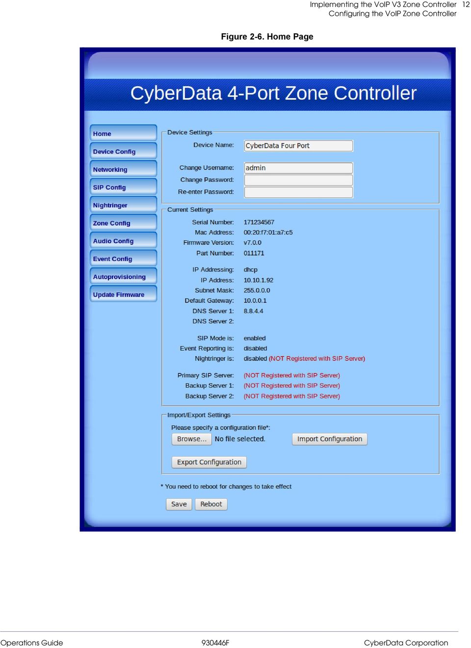
18 13 4. On the Home Page, review the setup details and navigation buttons described in Table 2-4. Web Page Item Device Settings Device Name Change Username Change Password Re-enter Password Current Settings Serial Number Mac Address Firmware Version Part Number IP Addressing IP Address Subnet Mask Default Gateway DNS Server 1 DNS Server 2 SIP Mode is Event Reporting is Nightring is Primary SIP Server Description Shows the device name (25 character limit). Type in this field to change the username (25 character limit). Type in this field to change the password (19 character limit). Type the password again in this field to confirm the new password (19 character limit). Shows the device serial number. Shows the device Mac address. Shows the current firmware version. Shows the 01 part number of the device. Shows the current IP addressing setting (DHCP or Static). Shows the current IP address. Shows the current subnet mask address. Shows the current default gateway address. Shows the current DNS Server 1 address. Shows the current DNS Server 2 address. Shows the current status of the SIP Mode. Shows the current status of the Event Reporting. Shows the current status of the Nightringer. Shows the current status of the Primary SIP Server. Backup Server 1 Shows the current status of Backup Server 1. Backup Server 2 Shows the current status of Backup Server 2. Import/Export Settings Table 2-4. Home Page Overview Press the Browse button to select a configuration file to import. Press the Import Configuration button to save a board configuration to the board. Note: The board will have to be reset before changes will take effect. Press the Export Configuration button to download the current board configuration. Click the Save button to save your configuration settings. Note: You need to reboot for changes to take effect. Click on the Reboot button to reboot the system.
. Type in this field to change the password (19 character limit).")
19 14 At this point you can: Review the VoIP Zone Controller s Current Settings. Use the RTFM switch to restore the factory default settings. See Section 2.3.5, "Restore the Factory Default Settings as Required". Configure the network parameters. Click the Networking button and refer to Section 2.4.5, "Configure the Network Parameters" for instructions. Configure the SIP parameters. Click SIP Config and see Section 2.4.6, "Configure the SIP Parameters". Configure the Zone parameters. Click Zone Config and see Section 2.4.8, "Configure the Zone Parameters" for instructions. Note Click the Upgrade Firmware button any time you need to upload new versions of the firmware. Refer to Section 2.5, "Upgrading the Firmware" for instructions.

20 Configure the Device Parameters 1. Click the Device Configuration button to open the Device Configuration page. See Figure 2-7. Figure 2-7. Device Configuration Page

21 16 2. On the Device Configuration page, you may enter values for the parameters indicated in Table 2-5. Table 2-5. Device Configuration Parameters Web Page Item Miscellaneous Settings Beep on Initialization Beep on Page Test Audio Port 1 through Port 4 Description When selected, you will hear a beep when the speaker initializes. When selected, you will hear a beep when a page is sent from the device. Select the desired port(s) for the audio test. Click on the Test Audio button to do an audio test. When the Test Audio button is pressed, you will hear a voice message for testing the device audio quality and volume. Click the Save button to save your configuration settings. Note: You need to reboot for changes to take effect. Click on the Reboot button to reboot the system. 3. After changing the parameters, click the Save button.
22 Configure the Network Parameters Configuring the network parameters enables your network to recognize the VoIP Zone Controller and communicate with it. Click Network Setup on the Home page to open the Network Configuration page. Figure 2-8. Network Setup Page
23 18 On the Network Setup page, enter values for the parameters indicated in Table 2-6. Table 2-6. Network Configuration Parameters Web Page Item Stored Network Settings IP Addressing IP Address Subnet Mask Default Gateway DNS Server 1 DNS Server 2 Hostname VLAN ID (0-4095) VLAN Priority (0-7) DHCP Timeout DHCP Timeout in seconds Current Network Settings IP Address Subnet Mask Default Gateway DNS Server 1 DNS Server 2 Description Shows the settings stored in non-volatile memory. Select either DHCP IP Addressing or Static IP Addressing by marking the appropriate radio button. If you select Static, configure the remaining parameters indicated in Table 2-6. If you select DHCP, go to Step 3. Enter the Static IP address. Enter the Subnet Mask address. Enter the Default Gateway address. Enter the DNS Server 1 address. Enter the DNS Server 2 address. This is the hostname provided to the DHCP server. This can be used in conjunction with a DNS server to address the device by host name instead of by IP address. Check your DHCP server and DNS server documentation for more information. Enter the VLAN ID number. Note: The device supports Q VLAN tagging support. The switch port connected to the device will need to be in trunking mode for the VLAN tags to propagate. Enter the VLAN priority number. Enter the desired timeout duration (in seconds) that the device will wait for a response from the DHCP server before defaulting back to the stored static IP address. Note: A value of -1 will cause the device to retry indefinitely and a value of 0 will cause the device to reset to a default of 60 seconds. Shows the current network settings. Shows the current Static IP address. Shows the current Subnet Mask address. Shows the current Default Gateway address. Shows the current DNS Server 1 address. Shows the current DNS Server 2 address. Click the Save button to save your configuration settings. Note: You need to reboot for changes to take effect. Click on the Reboot button to reboot the system. On this page: 1. Specify whether you use Static or DHCP IP Addressing by marking the appropriate radio button. Then, if you select Static, go to Step 2.
24 19 2. For Static IP Addressing, also enter values for the following parameters: The VoIP Zone Controller s IP Address: The VoIP Zone Controller is delivered with a factory default IP address. Change the default address to the correct IP address for your system. The Subnet Mask. The Default Gateway. 3. Click Save when you are finished. 4. Click Reboot for the new settings to take effect.
25 Configure the SIP Parameters The SIP parameters enable the VoIP Zone Controller to contact and register with the SIP server. On the Home page, click SIP Config to open the SIP Configuration page. Figure 2-9. SIP Configuration Page
26 21 5. On the SIP Setup page, enter values for the parameters indicated in Table 2-7. Table 2-7. SIP Configuration Parameters Web Page Item Enable SIP Operation SIP Settings SIP Server Backup SIP Server 1 Backup SIP Server 2 Use Cisco SRST Remote SIP Port Local SIP Port Outbound Proxy Outbound Proxy Port SIP User ID Authenticate ID Authenticate Password Register with a SIP Server Re-registration Interval (in seconds) Unregister on Boot Disable rport Discovery Buffer SIP Calls Description Enables or disables SIP operation. Type the SIP server represented as either a numeric IP address in dotted decimal notation or the fully qualified host name (255 character limit [FQDN]). Use this field to set the address (in dotted decimal notation or as a canonical name) for the first backup SIP Server. This field can accept canonical names of up to 255 characters in length. Use this field to set the address (in dotted decimal notation or as a canonical name) for the second backup SIP Server. This field can accept canonical names of up to 255 characters in length. When selected, the backup servers are handled according to Cisco SRST (Survivable Remote Site Telephony). Type the Remote SIP Port number (default 5060) (8 character limit). Type the Local SIP Port number (default 5060) (8 character limit). Type the Outbound Proxy as either a numeric IP address in dotted decimal notation or the fully qualified host name (255 character limit [FQDN]). Type the Outbound Proxy Port number (8 character limit). Type the SIP User ID (up to 64 alphanumeric characters). Type the Authenticate ID (up to 64 alphanumeric characters). Type the Authenticate Password (up to 64 alphanumeric characters). Check this box to enable SIP Registration. For information about Point-to-Point Configuration, see Section , "Point-to-Point Configuration". The Nightringer Registration lease time ( seconds)." Send one registration with an expiry of 0 on boot. Check this box prevent the device from including the public WAN IP address in the contact information that is sent to the remote SIP servers. This will generally only need to be enabled when using an SBC in conjunction with a remote SIP server. When this is enabled, SIP calls to the device will be stored in memory and will play when either the call is terminated or the buffer is full. The receive buffer is 2MB in size and this is equal to about four minutes of ulaw encoded audio.
27 22 Table 2-7. SIP Configuration Parameters (continued) Web Page Item Call Disconnection Terminate call after delay (in seconds) Misc Settings RTP Port (even) Description Type the desired number of seconds that you want to transpire after a connection delay before a call is terminated. Note: A value of 0 will disable this function. Specify the port number used for the RTP stream after establishing a SIP call. This port number has to be an even number and defaults to Click the Save button to save your configuration settings. Note: You need to reboot for changes to take effect. Click on the Reboot button to reboot the system. 1. Enter the IP address of the SIP Server. 2. Enter the port numbers used for SIP signaling: a. Remote SIP Port b. Local SIP Port
28 23 3. Enter the SIP registration parameters: a. SIP User ID b. Authenticate ID c. Authenticate Password 4. For SIP Registration, designate whether you want the device to register with your SIP server. 5. At Unregister on Reboot: a. Select Yes to automatically unregister the VoIP Zone Controller when you reboot it. b. Select No to keep the VoIP Zone Controller registered when you reboot it. 6. In the Register Expiration field, enter the number of seconds the VoIP Zone Controller registration lease remains valid with the SIP Server. The VoIP Zone Controller automatically reregisters with the SIP server before the lease expiration timeout. 7. Click Save. 8. Click Reboot for the new settings to take effect.
29 Point-to-Point Configuration When the board is set to not register with a SIP server, it's possible to set the device to dial out to a single endpoint. To do this, do the following: 1. On the SIP Configuration page (Figure 2-10), make sure that the Register with a SIP Server parameter is not selected. 2. Type the IP address of the remote device that you want to contact into the Dial out Extension field Note Note The delayed DTMF functionality is available in the Point-to-Point Mode. Establishing point-to-point SiP calls may not work with all phones. Figure SIP Configuration Page Set to Point-to-Point Mode Device is set to NOT register with a SIP server
30 Configure the Night Ringer Parameters Caution Nightringer requires SIP Registration. Nightringer cannot be used in peer to peer mode. GENERAL ALERT 1. Click on the Nightringer button to open the Nightringer Configuration page. See Figure Figure Nightringer Configuration Setup
31 26 2. On the Nightringer Configuration page, enter values for the parameters indicated in Table 2-8. Web Page Item Enable Nightringer Nightringer Settings SIP Server Description When the nightringer is enabled, the unit will attempt to register a second extension with the SIP server. Any calls made to this extension will play a ringtone. Type the SIP server represented as either a numeric IP address in dotted decimal notation. Remote SIP Port Type the Remote SIP Port number (default 5060) (8 character limit). Local SIP Port Type the Local SIP Port number (default 5060) (8 character limit). Note: This value cannot be the same as the Local SIP Port found on the SIP Configuration Page. Outbound Proxy Outbound Proxy Port User ID Authenticate ID Authenticate Password Re-registration Interval (in seconds) Play audio on ports Table 2-8. Nightringer Configuration Parameters Type the Outbound Proxy as either a numeric IP address in dotted decimal notation or the fully qualified host name (255 character limit [FQDN]). Type the Outbound Proxy Port number (8 character limit). Type the User ID (up to 64 alphanumeric characters). Type the Authenticate ID (up to 64 alphanumeric characters). Type the Authenticate Password (up to 64 alphanumeric characters). The Nightringer Registration lease time ( seconds)." When selected, a user-defined audio file is sent to the specified port(s) when the night ringer is activated. Click the Save button to save your configuration settings. Note: You need to reboot for changes to take effect. Click on the Reboot button to reboot the system. 3. After changing the parameters, click on the Save button. 4. Click Reboot for the new settings to take effect.
32 Configure the Zone Parameters Each audio output jack on the VoIP Zone Controller represents a port. A Zone is comprised of a combination of one or more ports. You will need to plug any ports that are used on the VoIP Zone Controller into an analog amplifier. Any speakers attached to the amplifier will be present in the port. 1. Click on the Zone Config button to open the Zone Configuration page. See Figure Figure Zone Configuration Setup
33 28 2. On the Zone Configuration page, enter values for the parameters indicated in Table 2-9. Web Page Item Bypass SIP DTMF Entry Enable Multicast Operation Zones Port 1 through Port 4 Checkboxes Security Code Description When selected, the ports in Zone 00 will be paged without waiting for DTMF entry. Note: Bypassing DTMF will result in all SIP calls being played to Zone 0. Enables or disables multicast operation. See Section , "Configuring the Multicast Parameters" Check the box for the port(s) that comprise the zone. Type the security code in this field. Multicast Address Enter the multicast IP Address for this multicast group (15 character limit). Multicast Port Buffer Multicast Table 2-9. Zone Configuration Parameters Enter the port number for this multicast group (5 character limit [range can be from 2000 to 65535]). Note: The multicast ports have to be even values. The webpage will enforce this restriction. When this is enabled, multicast pages to the device will be stored in memory and will play when either the page is terminated or the buffer is full. The receive buffer is 2MB in size and this is equal to about four minutes of ulaw encoded audio. Click the Save button to save your configuration settings. Note: You need to reboot for changes to take effect. Click on the Reboot button to reboot the system. 3. After changing the parameters, click on the Save button. 4. Click Reboot for the new settings to take effect Operating the VoIP Zone Controller To operate the VoIP Zone Controller: 1. Call to make a page. The VoIP Zone Controller will generate a tone over the phone. 2. When you hear this tone, enter the two-digit code for the group that you want to page. Note If the Bypass SIP DTMF Entry setting is enabled, go to Step If the zone is valid, the VoIP Zone Controller will play the user-defined "good zone" sound. Go to Step 4. Note If the zone is invalid, the VoIP Zone Controller will play the user-defined "bad zone" sound. Repeat Step 2.
34 29 4. When you hear the "good zone" tone, you can begin speaking Configuring the Multicast Parameters The Multicast configuration parameters allows the Zone Controller to join up to one paging zone for receiving a ulaw/alaw encoded RTP audio stream. A paging zone can consist of one or many CyberData multicast group-enabled products. There is no limit to how many devices can be in a given paging zone. A multicast group is defined by a multicast address and port number. Each multicast group is assigned a priority, allowing simultaneously arriving pages to be serviced based on importance. Multicast groups are compatible with IGMP through version three.
35 Configure the Audio Parameters Click the Audio Config button to open the Audio Configuration page. See Figure The Audio Configuration page is used to add custom audio to the board. User uploaded audio will take precedence over the audio files shipped with the VoIP Zone Controller. Figure Audio Configuration Page
36 31 Figure Audio Configuration Page

37 32 Figure Audio Configuration Page Note To test an audio file, first select the ports (located at the bottom of the Audio Configuration Page) that you want to play the audio file to, and then press the Play button for the desired audio file.
38 33 On the Audio Configuration page, enter values for the parameters indicated in Table Note Each entry on the Audio Configuration page replaces one of the stock audio files on the board. When the input box displays the word default, the VoIP Zone Controller is using the stock audio file. If that file is replaced with a user file, it will display the uploaded filename. Table Audio Configuration Parameters Web Page Item Description Audio Files 0-9 The name of the audio configuration option is the same as the spoken audio that plays on the board (24 character limit). '0' corresponds to the spoken word zero. '1' corresponds to the spoken word one. '2' corresponds to the spoken word two. '3' corresponds to the spoken word three. '4' corresponds to the spoken word four. '5' corresponds to the spoken word five. '6' corresponds to the spoken word six. '7' corresponds to the spoken word seven. '8' corresponds to the spoken word eight. '9' corresponds to the spoken word nine. Dot Audio test Enter Code Invalid Code Enter Zone Invalid Zone Page tone Your IP Address is Rebooting Restoring default Night Ring Ports to play test audio Port 1 through Port 4 Corresponds to the spoken word dot. (24 character limit). Corresponds to the message This is the CyberData IP speaker test message... (24 character limit). Corresponds to the message Enter Code (24 character limit). Corresponds to the message Invalid Code (24 character limit). Corresponds to the message Enter Zone (24 character limit). Corresponds to the message Invalid Zone (24 character limit). Corresponds to a simple tone that is unused by default (24 character limit). Corresponds to the message Your IP address is... (24 character limit). Corresponds to the spoken word Rebooting (24 character limit). Corresponds to the message Restoring default (24 character limit). Specifies the ringtone for nightring. By default this parameter uses the same audio file that is selected for the Ring Tone parameter. Select the desired port(s) for the audio test. The Browse button will allow you to navigate to and select an audio file. The Play button will play that audio file. The Delete button will delete any user uploaded audio and restore the stock audio file.
39 34 Table Audio Configuration Parameters (continued) Web Page Item Description The Save button will download a new user audio file to the board once you've selected the file by using the Browse button. The Save button will delete any pre-existing user-uploaded audio files.


40 User-created Audio Files User created audio files should be saved in the following format: RIFF (little-endian) data, WAVE audio, Microsoft PCM, 16 bit, mono 8000 Hz You can use the free utility Audacity to convert audio files into this format. See Figure 2-16 through Figure Figure Audacity 1 Figure Audacity 2
41 36 When you export an audio file with Audacity, save the output as: WAV (Microsoft) signed 16 bit PCM. Figure WAV (Microsoft) signed 16 bit PCM WAV (Microsoft) signed 16 bit PCM
42 Configure the Event Parameters Click the Event Config button to open the Event Configuration page (Figure 2-19). The Event Configuration page specifies a remote server that can be used to receive HTTP POST events when actions take place on the board. Figure Event Configuration Page
43 38 Table 2-11 shows the web page items on the Event Configuration page. Table Event Configuration Web Page Item Enable Event Generation Remote Event Server Remote Event Server IP Remote Event Server Port Remote Event Server URL Events Enable Call Active Events Enable Call Terminated Events Enable Night Ring Events Enable Multicast Start Enable Multicast Stop Enable Power On Events Enable 60 Second Heartbeat Events Description When selected, Event Generation is enabled. Type the Remote Event Server IP address. (64 character limit) Type the Remote Event Server port number. (8 character limit) Type the Remote Event Server URL. (127 character limit) When selected, Call Active Events are enabled. When selected, Call Terminated Events are enabled. When selected, there is a notification when the unit receives a night ring. When selected, Multicast Start Events are enabled. When selected, Multicast Stop Events are enabled. When selected, Power On Events are enabled. When selected, 60 Second Heartbeat Events are enabled. Click the Save button to save your configuration settings. Note: You need to reboot for changes to take effect. Click on the Test Event button to test an event. Click on the Reboot button to reboot the system.
44 Example Packets for Events The server and port are used to point to the listening server and the 'Remote Event Server URL' is the destination URL (typically the script running on the remote server that's used to parse and process the POST events). Note The XML is URL-encoded before transmission so the following examples are not completely accurate. Here are example packets for every event: POST xmlparse_engine HTTP/1.1 Host: User-Agent: CyberData/1.0.0 Content-Length: 197 Content-Type: application/x-www-form-urlencoded <?xml version="1.0" encoding="iso "?> <cyberdata NAME='CyberData VoIP Device' MAC='0020f70015b6'> <event>poweron</event> </cyberdata> POST xmlparse_engine HTTP/1.1 Host: User-Agent: CyberData/1.0.0 Content-Length: 199 Content-Type: application/x-www-form-urlencoded <?xml version="1.0" encoding="iso "?> <cyberdata NAME='CyberData VoIP Device' MAC='0020f70015b6'> <event>heartbeat</event> </cyberdata> POST xmlparse_engine HTTP/1.1 Host: User-Agent: CyberData/1.0.0 Content-Length: 201 Content-Type: application/x-www-form-urlencoded <?xml version="1.0" encoding="iso "?> <cyberdata NAME='CyberData VoIP Device' MAC='0020f70015b6'> <event>call_active</event> </cyberdata> POST xmlparse_engine HTTP/1.1 Host: User-Agent: CyberData/1.0.0 Content-Length: 205 Content-Type: application/x-www-form-urlencoded <?xml version="1.0" encoding="iso "?> <cyberdata NAME='CyberData VoIP Device' MAC='0020f70015b6'> <event>call_terminated</event> </cyberdata>
45 40 POST xmlparse_engine HTTP/1.1 Host: User-Agent: CyberData/1.0.0 Content-Length: 234 Content-Type: application/x-www-form-urlencoded <?xml version="1.0" encoding="iso "?> <cyberdata NAME='CyberData VoIP Device' MAC='0020f70015b6'> <event>multicast_start</event> <index>8</index> </cyberdata> POST xmlparse_engine HTTP/1.1 Host: User-Agent: CyberData/1.0.0 Content-Length: 233 Content-Type: application/x-www-form-urlencoded <?xml version="1.0" encoding="iso "?> <cyberdata NAME='CyberData VoIP Device' MAC='0020f70015b6'> <event>multicast_stop</event> <index>8</index> </cyberdata> POST xmlparse_engine HTTP/1.1 Host: User-Agent: CyberData/1.0.0 Content-Length: 234 Content-Type: application/x-www-form-urlencoded <?xml version="1.0" encoding="iso "?> <cyberdata NAME='CyberData VoIP Device' MAC='0020f70015b6'> <event>nightringing</event> </cyberdata>
46 Configure the Autoprovisioning Parameters 1. Click the Autoprovisioning button to open the Autoprovisioning Configuration page. See Figure Figure Autoprovisioning Configuration Page
47 42 2. On the Autoprovisioning Configuration page, you may enter values for the parameters indicated in Table Table Autoprovisioning Configuration Parameters Autoprovisioning Web Page Item Enable Autoprovisioning Get Autoprovisioning from DHCP Download Protocol Autoprovisioning Server (IP Address) Autoprovisioning Filename Autoprovisioning Autoupdate (in minutes) Autoprovision at time (HHMMSS) Autoprovision when idle (in minutes > 10) Clock NTP Server Posix Timezone String Set Time with External NTP Server on boot Periodically update with time server Time update period (in hours) Description See Section , "Autoprovisioning". See Section , "Autoprovisioning". Allows you to select whether the autoprovisioning file is acquired via TFTP or HTTP. See Section , "Autoprovisioning" (15 character limit). Type the desired name for the autoprovisioning file. Type the desired time (in minutes) that you want the Autoprovisioning feature to update (6 character limit). Note: A value of 0 will disable this option. Type the desired time of day that you want the Autoprovisioning feature to update (must be 6 characters). Note: An empty value will disable this option. Type the desired time (in minutes greater than 10) that you want the Autoprovisioning feature to update after a certain amount of idle time (6 character limit). Note: A value of 0 will disable this option. Press the Get Autoprovisioning Template button to create an autoprovisioning file for this unit. See Section , "Get Autoprovisioning Template Button" Allows you to select the NTP server (64 character limit). See Section , "Time Zone Strings" (43 character limit). When selected, the time is set with an external NTP server when the device restarts. When selected, the time is periodically updated with a time server. Allows you to select the time updated period (in hours) (4 character limit). Allows you to set the time from the NTP server. Current Time Current Time in 24 hour format (HHMMSS) Allows you to input the current time in the 24 hour format. (6 character limit) Click on this button to set the clock after entering the current time. Click the Save button to save your configuration settings. Note: You need to reboot for changes to take effect.
48 43 Table Autoprovisioning Configuration Parameters (continued) Web Page Item Description Click on the Reboot button to reboot the system. 3. After changing the parameters, click the Save button Autoprovisioning Autoprovisioning File It is not necessary to set every option found in the autoprovisioning template. As long as the XML is valid, the file can contain any subset. Options not autoprovisioned will default to the values stored in the on board memory. For example if you only wanted to modify the device name, the following would be a valid autoprovisioning file: <?xml version="1.0" encoding="utf-8"?> <specific> <MiscSettings> <DeviceName>auto Intercom</DeviceName> </MiscSettings> </specific> Get Autoprovisioning from DHCP When this option is checked, the device will automatically fetch its autoprovisioning server address from the DHCP server. The device will use the address specified in OPTION 150 (TFTP-servername) or OPTION 66. If both options are set, the device will use OPTION 150. Refer to the documentation of your DHCP server for setting up OPTION 150. To set up a Linux DHCPD server to serve autoprovisioning information (in this case using both option 66 and 150), here's an example dhcpd.conf: # dhcpd.conf # # Configuration file for ISC dhcpd (see 'man dhcpd.conf') # ddns-update-style ad-hoc; option option-150 code 150 = ip-address; subnet netmask { max-lease-time 120; default-lease-time 120; option routers ; option subnet-mask ; option domain-name "voiplab"; option domain-name-servers ; option time-offset -8; # Pacific Standard Time option tftp-server-name " "; option option ; range ;}
49 44 Autoprovisioning Server (IP Address) Instead of using DHCP to provide the autoprovisioning tftp server address, you can specify an address manually. Autoprovisioning Autoupdate When the device is set to autoprovision either after a period of time, or when idle, or at a time of day, the device will do the following: Re-download the autoprovisioning file. Compare this new file to the one downloaded on boot, and if it finds differences, force a system reset. After rebooting, the board will configure itself according to this new file. Autoprovisioned An Autoprovisioned firmware upgrade only happens after a reboot, will take roughly three minutes, Firmware Upgrades and the web page will be unresponsive during this time. The 'FirmwareVersion' value in the xml file must match the version stored in the 'FirmwareFile'. <FirmwareVersion>v10.0.3</FirmwareVersion> <FirmwareFile>1003-intercom-uImage</FirmwareFile> If these values are mismatched, the board can get stuck in a loop where it goes through the following sequence of actions: 1. The board downloads and writes a new firmware file. 2. After the next reboot, the board recognizes that the firmware version does not match. 3. The board downloads and writes the firmware file again. CyberData has timed a firmware upgrade at 140 seconds. Therefore, if you suspect the board is stuck in a loop, either remove or comment out the FirmwareVersion line in the XML file and let the board boot as it normally does. Autoprovisioned Audio Files Audio files are stored in non-volatile memory and an autoprovisioned audio file will only have to be downloaded once for each device. Loading many audio files to the device from the web page could cause it to appear unresponsive. If this happens, wait until the transfer is complete and then refresh the page. The device uses the file name to determine when to download a new audio file. This means that if you used autoprovisioning to upload a file and then changed the contents of this file at the TFTP server, the device will not recognize that the file has changed (because the file name is the same). Since audio files are stored in non-volatile memory, if autoprovisioning is disabled after they have been loaded to the board, the audio file settings will not change. You can force a change to the audio files on the board by clicking Restore Default on the Audio Configuration page or by changing the autoprovisioning file with default set as the file name.

50 Get Autoprovisioning Template Button The Get Autoprovisioning Template button allows the user to generate, download, edit, and then store an autoprovisioning template on the server that serves the autoprovisioning files for devices. To generate an autoprovisioning template directly from the device, complete the following steps: 1. On the Autoprovisioning page, click on the Get Autoprovisioning Template button. 2. You will see a window prompting you to save a configuration file (.config) to a location on your computer (Figure 2-21). The configuration file is the basis for the default configuration settings for your unit). 3. Choose a location to save the configuration file and click on OK. See Figure Figure Configuration File 4. At this point, you can open and edit the autoprovisioning template to change the configuration settings in the template for the unit. 5. You can then upload the autoprovisioning file to a TFTP or HTTP server where the file can be loaded onto other devices.
51 Time Zone Strings The posix time zone string tells the internal date and time utilities how to handle daylight savings time for different time zones. Table 2-13 shows some common strings. Table Common Time Zone Strings Time Zone US Pacific time US Mountain time US Eastern Time Phoenix Arizona a US Central Time Time Zone String PST8PDT,M3.2.0/2:00:00,M11.1.0/2:00:00 MST7MDT,M3.2.0/2:00:00,M11.1.0/2:00:00 EST5EDT,M3.2.0/2:00:00,M11.1.0/2:00:00 MST7 CST6DST,M3.2.0/2:00:00,M11.1.0/2:00:00 a.phoenix, Arizona does not use daylight savings time. Table 2-14 shows a breakdown of the parts that constitute the following time zone string: CST6DST,M3.2.0/2:00:00,M11.1.0/2:00:00 Table Time Zone String Parts Time Zone String Part Meaning CST6CDT The time zone offset from GMT and three character identifiers for the time zone. CST Central Standard Time 6 The (hour) offset from GMT/UTC CDT Central Daylight Time M3.2.0/2:00:00 The date and time when daylight savings begins. M3 The third month (March).2 The 2nd occurrence of the day (next item) in the month.0 Sunday /2:00:00 Time of day to change M11.1.0/2:00:00 The date and time when daylight savings ends. M11 The eleventh month (November).1 The 1st occurrence of the day (next item) in the month.0 Sunday /2:00:00 Time of day to change
52 47 Time Zone String Examples Table 2-15 has some more examples of time zone strings. Table Time Zone String Examples Time Zone Tokyo a Berlin b Time Zone String IST-9 CET-1MET,M3.5.0/1:00,M10.5.0/1:00 a.tokyo does not use daylight savings time. b.for Berlin, daylight savings time starts on the last Sunday in March at 01:00 UTC, and ends on the last Sunday in October at 01:00 UTC, and is one hour ahead of UTC. Time Zone Identifier A user-definable three or four character time zone identifier (such as PST, EDT, IST, MUT, etc) is needed at the beginning of the posix time zone string to properly set the time. However, the specific letters or numbers used for the time zone identifier are not important and can be any three or four letter or number combination that is chosen by the user. However, the time zone identifier cannot be blank. Figure Three or Four Character Time Zone Identifier You can also use the following URL when a certain time zone applies daylight savings time: World GMT Table Table 2-16 has information about the GMT time in various time zones. Table World GMT Table Time Zone GMT-12 GMT-11 GMT-10 GMT-9 GMT-8 GMT-7 GMT-6 GMT-5 GMT-4 GMT-3 GMT-2 GMT-1 GMT GMT+1 GMT+2 GMT+3 GMT+4 City or Area Zone Crosses Eniwetok Samoa Hawaii Alaska PST, Pacific US MST, Mountain US CST, Central US EST, Eastern US Atlantic, Canada Brazilia, Buenos Aries Mid-Atlantic Cape Verdes Greenwich Mean Time, Dublin Berlin, Rome Israel, Cairo Moscow, Kuwait Abu Dhabi, Muscat
53 48 Table World GMT Table (continued) Time Zone GMT+5 GMT+6 GMT+7 GMT+8 GMT+9 GMT+10 GMT+11 GMT+12 City or Area Zone Crosses Islamabad, Karachi Almaty, Dhaka Bangkok, Jakarta Hong Kong, Beijing Tokyo, Osaka Sydney, Melbourne, Guam Magadan, Soloman Is. Fiji, Wellington, Auckland
54 Upgrading the Firmware Upgrading the Firmware Uploading the Firmware GENERAL ALERT Caution Equipment Hazard: CyberData strongly recommends that you first reboot the device before attempting to upgrade the firmware of the device. See Section 2.5.2, "Reboot the Device". To upload the firmware from your computer: 1. Retrieve the latest firmware file from the Downloads page at: Note Table 2-17 shows some of the available firmware file names and functions. Table Firmware Firmware File Name 700-uImage-4port 700-uImage-4port_nosig Function Must be used to downgrade from v7.0.1 or higher Must be used to upgrade from v6.0.2 or lower GENERAL ALERT Caution Equipment Hazard: Users will not be able to upgrade directly from versions older than v7.0.0 to versions greater than v Users will have to upgrade to v7.0.0 then move on from there. 2. Unzip the firmware version file. This file may contain the following: Firmware file Release notes 3. Log in to the home page as instructed in Section 2.4.3, "Log in to the Configuration Home Page". 4. Click the Update Firmware menu button to open the Upgrade Firmware page. See Figure 2-23.
55 Upgrading the Firmware 50 Figure Upgrade Firmware Page 5. Select Browse, and then navigate to the location of the firmware file. 6. Click Submit. Note Note Do not reboot the board after pressing the Submit button. This starts the upgrade process. Once the device has uploaded the file, the Uploading Firmware countdown page appears, indicating that the firmware is being written to flash. The device will automatically reboot when the upload is complete. When the countdown finishes, the Upgrade Firmware page will refresh. The uploaded firmware filename should be displayed in the system configuration (indicating successful upload and reboot). Table 2-18 shows the web page items on the Upgrade Firmware page. Table Firmware Upgrade Parameters Web Page Item File Upload Firmware Version Description Shows the current firmware version. Use the Browse button to navigate to the location of the Intercom firmware file that you want to upload. Click on the Submit button to automatically upload the selected firmware and reboot the system.
56 Upgrading the Firmware Reboot the Device To reboot the device, log in to the web page as instructed in Section 2.4.3, "Log in to the Configuration Home Page". 1. Click Reboot (Figure 2-24). A normal restart will occur. Figure Reboot Button Reboot
57 52 Appendix A: Mounting the VoIP Zone Controller A.1 Mount the VoIP Zone Controller A.1.1 Mounting Components Before you mount the VoIP Zone Controller, make sure that you have received all of the parts for each VoIP Zone Controller. Refer to Table A-1. Table A-1. Wall Mounting Components (Part of the Accessory Kit) Quantity Part Name Illustration 2 #6 x 1 1/2-inch Screws 2 #6 Plastic-Ribbed Anchors
58 53 Mount the VoIP Zone Controller A.1.2 Mounting Procedure To mount the VoIP Zone Controller: 1. On the mounting location, mark and then drill two 3/16-inch ( inch) holes 3.5 inches apart from and parallel to each other for the plastic-ribbed anchors and screws. See Figure A Insert the plastic-ribbed anchors into the prepared holes. See Figure A Install the #6 screws into the plastic-ribbed anchors and leave approximately 1/8-inch gap from the screw head to the wall. See Figure A Determine which sides of the VoIP Zone Controller will be facing up, and then slide the VoIP Zone Controller down over the screws to latch onto the screws. Figure A-1. Mounting
59 54 Appendix A: Setting Up a TFTP Server A.1 Set up a TFTP Server Autoprovisioning requires a TFTP server for hosting the configuration file. A.1.1 In a LINUX Environment To set up a TFTP server on LINUX: 1. Create a directory dedicated to the TFTP server, and move the files to be uploaded to that directory. 2. Run the following command where /tftpboot/ is the path to the directory you created in Step 1: the directory that contains the files to be uploaded. For example: in.tftpd -l -s /tftpboot/your_directory_name A.1.2 In a Windows Environment You can find several options online for setting up a Windows TFTP server. This example explains how to use the Solarwinds freeware TFTP server, which you can download at: To set up a TFTP server on Windows: 1. Install and start the software. 2. Select File/Configure/Security tab/transmit Only. 3. Make a note of the default directory name, and then move the firmware files to be uploaded to that directory.
60 55 Appendix B: Troubleshooting/Technical Support B.1 Frequently Asked Questions (FAQ) Go to the following URL to see CyberData s list of frequently asked questions: B.1.1 Documentation The documentation for this product is released in an English language version only. You can download PDF copies of CyberData product documentation at:
61 56 Contact Information B.2 Contact Information Contact CyberData Corporation 3 Justin Court Monterey, CA USA Phone: 800-CYBERDATA ( ) Fax: Sales Sales Extension 334 Technical Support The fastest way to get technical support for your VoIP product is to submit a VoIP Technical Support form at the following website: The Support Form initiates a ticket which CyberData uses for tracking customer requests. Most importantly, the Support Form tells us which PBX system and software version that you are using, the make and model of the switch, and other important information. This information is essential for troubleshooting. Please also include as much detail as possible in the Comments section of the Support Form. Phone: (831) , Ext [email protected] Returned Materials Authorization To return the product, contact the Returned Materials Authorization (RMA) department: Phone: , Extension [email protected] When returning a product to CyberData, an approved CyberData RMA number must be printed on the outside of the original shipping package. Also, RMA numbers require an active VoIP Technical Support ticket number. A product will not be accepted for return without an approved RMA number. Send the product, in its original package, to the following address: CyberData Corporation 3 Justin Court Monterey, CA Attention: RMA "your RMA number" RMA Status Form If you need to inquire about the repair status of your product(s), please use the CyberData RMA Status form at the following web address:
62 57 Warranty B.3 Warranty CyberData warrants its product against defects in material or workmanship for a period of two years from the date of purchase. Should the product fail Within Warranty, CyberData will repair or replace the product free of charge. This warranty includes all parts and labor. Should the product fail Out of the Warranty period, a flat rate repair charge of one half of the purchase price of the product will be assessed. Repairs that are Within Warranty period but are damaged by improper installation, modification, or abuse are deemed Out of Warranty and will be charged at the Out of Warranty rate. A device is deemed Out of Warranty when its purchase date is longer than two years or when the device has been damaged due to human error during installation, modification, or abuse. A replacement unit will be offered at full cost if the device cannot be repaired. End of Life Devices out of warranty are included under this policy. However, End of Life devices are not eligible for our Spare in the Air program. End of Life devices are devices that are no longer produced or sold. Therefore, we cannot offer a Spare in the Air replacement. Technical support is still available for these devices. However, no firmware revisions or updates will be scheduled. If an End of Life device cannot be repaired, a replacement of a current version of the device may be offered at MSRP. Products shipped to CyberData, both within and out of warranty, are shipped at the expense of the customer. CyberData will pay return shipping charges for repaired products. CyberData shall not under any circumstances be liable to any person for any special, incidental, indirect or consequential damages, including without limitation, damages resulting from use or malfunction of the products, loss of profits or revenues or costs of replacement goods, even if CyberData is informed in advance of the possibility of such damages. B.3.1 Warranty & RMA Returns within the United States If service is required, you must contact CyberData Technical Support prior to returning any products to CyberData. Our Technical Support staff will determine if your product should be returned to us for further inspection. If Technical Support determines that your product needs to be returned to CyberData, an RMA number will be issued to you at this point. Your issued RMA number must be printed on the outside of the shipping box. No product will be accepted for return without an approved RMA number. The product in its original package should be sent to the following address: CyberData Corporation 3 Justin Court. Monterey, CA Attn: RMA "xxxxxx"
63 58 Warranty B.3.2 Warranty & RMA Returns outside of the United States If you purchased your equipment through an authorized international distributor or reseller, please contact them directly for product repairs. B.3.3 Spare in the Air Policy CyberData now offers a Spare in the Air no wait policy for warranty returns within the United States and Canada. More information about the Spare in the Air policy is available at the following web address: B.3.4 Return and Restocking Policy For our authorized distributors and resellers, please refer to your CyberData Service Agreement for information on our return guidelines and procedures. For End Users, please contact the company that you purchased your equipment from for their return policy. B.3.5 Warranty and RMA Returns Page The most recent warranty and RMA information is available at the CyberData Warranty and RMA Returns Page at the following web address:
64 59 Index Numerics 100 Mbps indicator LED 7 A act LED 7 activity LED 7 address, configuration login 11 addressing DHCP 9, 18 static 9, 18 admin username and password 11 amplifier connections cables used 1, 5 audio activity LED 7 audio configuration 30 night ring tone parameter 33 audio configuration page 30 audio files, user-created 35 authenticate ID and password for SIP server registration 23 Autoprovision at time (HHMMSS) 42 autoprovision at time (HHMMSS) 42 autoprovision when idle (in minutes > 10) 42 autoprovisioning 42, 43 autoprovisioned audio files 44 autoprovisioned firmware upgrades 44 autoprovisioning autoupdate 44 autoprovisioning from DHCP 43 autoprovisioning server (IP address) 44 get autoprovisioning template button 42 autoprovisioning autoupdate (in minutes) 42 autoprovisioning configuration 41, 42 autoprovisioning filename 42 autoprovisioning server (IP Address) 42 B backup SIP server 1 21 backup SIP server 2 21 backup SIP servers, SIP server backups 21 blue status LED 7 bypass DTMF 28 C cables used to connect the paging device to the legacy analog amplifiers 1, 5 changing the web access password 15 changing default username and password for configuration GUI 11 Cisco SRST 21 configurable parameters 13, 16, 18 configuration information 9 configuration page configurable parameters 13, 16, 18 connection speed 2 10 Mbps Mbps 7 connection speeds 7 connections cables used 1, 5 contact information 56 contact information for CyberData 56 Current Network Settings 18 current network settings 18 current settings, reviewing 14 CyberData contact information 56 D default gateway 8 IP address 8 subnet mask 8 username and password 8 default gateway 8, 18 default gateway for static addressing 19 default login address 11 default password for configuration GUI 11 default settings, restoring 8 default username and password for configuration GUI 11 device configuration 15 device configuration parameters 42 the device configuration page 41 device configuration page 15 device configuration parameters 16 device configuration password changing for web configuration access 15 DHCP addressing 9, 18 DHCP IP addressing 18 dimensions 2
65 60 discovery utility program 11 DNS server 18 door sensor 33 download protocol, HTTP or TFTP 42 E enable night ring events 38 event configuration enable night ring events 38 expiration time for SIP server lease 21, 23, 26 export configuration button 13 export settings 13 F features 2 firmware where to get the latest firmware 49 firmware, upgrade 14, 49 G get autoprovisioning from DHCP 42 get autoprovisioning template 42 get autoprovisioning template button 42 GMT table 47 GMT time 47 GUI username and password 11 I identifier names (PST, EDT, IST, MUT) 47 identifying your product 1 illustration of device mounting process 52 import configuration button 13 import settings 13 import/export settings 13 IP address 8, 18 SIP server 22 IP addressing 18 default IP addressing setting 8 L lease, SIP server expiration time 21, 23, 26 link LED 7 Linux, setting up a TFTP server on 54 local SIP port 21, 22 log in address 11 logging in to configuration GUI 11 M mounting procedure 53 mounting the device 52 multicast configuration 24 Multicast IP Address 28 N navigation (web page) 10 navigation table 10 network configuration page 17 network parameters, configuring 17 network setup button 14, 17 network, connecting to 6 Nightringer 25, 45 Nightringer in peer to peer mode (cannot be used) 25 nightringer settings 26 Nightringer, SIP registration required 25 NTP server 42 O operating the zone controller 28 output connections 1, 5 P paging LED 7 part number 2 parts list 3 password configuration GUI 9, 11 for SIP server login 21 restoring the default 8 SIP server authentication 23 pgroups configuration 14 point-to-point configuration 24 port local SIP 21, 22 remote SIP 21, 22 posix timezone string timezone string 42
66 61 power connecting to 5 requirement 2 power status LED 7 product mounting 52 product overview 1 R reboot 50, 51 unregistering from SIP server during 23 registration and expiration, SIP server lease expiration 23 regulatory compliance 2 remote SIP port 21, 22 required configuration for web access username and password 9, 11 resetting the IP address to the default 52, 55 restoring factory default settings 8 return and restocking policy 58 RMA returned materials authorization 56 RMA status 56 rport discovery setting, disabling 21 RTFM switch 8 S sales 56 server SIP 14 TFTP 54 server address, SIP 21 service 56 set the time from the NTP server 42 set time with external NTP server on boot 42 SIP enable SIP operation 21 local SIP port 21 user ID 21 SIP configuration SIP Server 21 SIP configuration page 20 SIP configuration parameters 21 outbound proxy 21, 26 registration and expiration, SIP server lease 21, 26 unregister on reboot 21 user ID, SIP 21 SIP registration 21 SIP remote SIP port 21 SIP server 21 password for login 21 unregister from 21 user ID for login 21 SIP server configuration 14 SIP server parameters, configuring 9 SIP settings 21, 22 SIP setup button 14, 20 Spare in the Air Policy 58 specifications 2 speed of connection 2 SRST 21 static addressing 9, 18 static IP addressing 18 status LED 7 Stored Network Settings 18 subnet mask 8, 18 subnet mask static addressing 19 supported protocols 2 T tech support 56 technical support, contact information 56 TFTP server 54 time zone string examples 47 U unregister from SIP server 23 upgrade firmware 14, 49 upgrade firmware button 14 user ID for SIP server login 21 user ID for SIP server registration 23 username changing for web configuration access 15 restoring the default 8 username for configuration GUI 9, 11 V VLAN ID 18 VLAN Priority 18 VLAN tagging support 18 VLAN tags 18 W warranty 57 warranty & RMA returns outside of the United States 58
67 62 warranty and RMA returns page 58 warranty policy at CyberData 57 web access password 8 web access username 8 web configuration log in address 11 web page navigation 10 web page navigation 10 weight 2 Windows, setting up a TFTP server on 54 Z zone controller configuration 9 zone controller operation 28 zone setup bypass DTMF 28
VoIP Zone Controller: 4-Port Audio Out Operations Guide
 The IP Endpoint Company VoIP Zone Controller: 4-Port Audio Out Operations Guide SiP Compliant 010881 Document Part #930109D for Firmware Version 1.0.6 CyberData Corporation 3 Justin Court Monterey, CA
VoIP V3 Zone Controller 4-Port Audio Out Operations Guide
 The IP Endpoint Company VoIP V3 Zone Controller 4-Port Audio Out Operations Guide Part #011171 Document Part #930446B for Firmware Version 6.0.2 CyberData Corporation 3 Justin Court Monterey, CA 93940
How To Set Up An Office Ringer (Voip) For A Paging Device (Vip) (Vivoip) Or Office Ringleer (Vio) (Sip) On A Pager) (Powerline)
 For A Paging Device (Vip) (Vivoip) Or Office Ringleer (Vio) (Sip) On A Pager) (Powerline)") The IP Endpoint Company VoIP Indoor Office Ringer Operations Guide Part #011149*, RAL 9003, Signal White Color Document Part #930386E for Firmware Version 6.1.0 CyberData Corporation 3 Justin Court Monterey,
The IP Endpoint Company VoIP Indoor Office Ringer Operations Guide Part #011149*, RAL 9003, Signal White Color Document Part #930386E for Firmware Version 6.1.0 CyberData Corporation 3 Justin Court Monterey,
SIP Strobe Operations Guide
 The IP Endpoint Company SIP Strobe Operations Guide Part #011087 Document Part #930425D for Firmware Version 1.0.1 CyberData Corporation 3 Justin Court Monterey, CA 93940 (831) 373-2601 SIP Strobe Operations
CyberData SIP Paging Adapter Integration with Zultys MX
 The IP Endpoint Company CyberData SIP Paging Adapter Integration with Zultys MX Author: Zultys Technical Support Department Document Part #930710A CyberData Corporation 3 Justin Court Monterey, CA 93940
Configuring CyberData Devices for Intermedia Hosted PBX
 The IP Endpoint Company Configuring CyberData Devices for Intermedia Hosted PBX This procedure was written by: CyberData Corporation 3 Justin Court Monterey, CA 93940 T:831-373-2601 F: 831-373-4193 www.cyberdata.net
VoIP V3 Outdoor Intercom Operations Guide
 The IP Endpoint Company VoIP V3 Outdoor Intercom Operations Guide Part #011186 Document Part #930472D for Firmware Version 7.1.6 CyberData Corporation 3 Justin Court Monterey, CA 93940 (831) 373-2601 VoIP
CyberData VoIP V2 Speaker with VoIP Clock Kit Configuration Guide for OmniPCX Enterprise
 CyberData VoIP V2 Speaker with VoIP Clock Kit Configuration Guide for OmniPCX Enterprise CyberData Corporation 2555 Garden Road Monterey, CA 93940 T:831-373-2601 F: 831-373-4193 www.cyberdata.net 2 Introduction
VoIP Intercom Operations Guide
 VoIP Intercom Operations Guide Part #010935A CyberData Corporation 2555 Garden Road Monterey, CA 93940 (831) 373-2601 930181E PoE VoIP Intercom Operations Guide 930181E Part # 010935A COPYRIGHT NOTICE:
IP Session/Cyberdata IP Endpoints. IP Paging and Access Control
 The IP Endpoint Company IP Session/Cyberdata IP Endpoints. IP Paging and Access Control Document Part #930550A CyberData Corporation 3 Justin Court Monterey, CA 93940 (831) 373-2601 COPYRIGHT NOTICE: 2012,
Configuring CyberData VoIP Ceiling Speakers
 NetVanta Unified Communications Technical Note Configuring CyberData VoIP Ceiling Speakers Introduction The CyberData Voice over IP (VoIP) ceiling speaker connects to existing local area networks (LANs)
NetComm V90 VoIP Phone Quick Start Guide Draft Release 0.1
 NetComm V90 VoIP Phone Quick Start Guide Draft Release 0.1 Copyright NetComm Ltd Overview NetComm V90 SIP VoIP Phone User Guide Table of Contents Overview... 3 V90 VoIP Phone Specification...4 Shipping
Management Software. Web Browser User s Guide AT-S106. For the AT-GS950/48 Gigabit Ethernet Smart Switch. Version 1.0.0. 613-001339 Rev.
 Management Software AT-S106 Web Browser User s Guide For the AT-GS950/48 Gigabit Ethernet Smart Switch Version 1.0.0 613-001339 Rev. A Copyright 2010 Allied Telesis, Inc. All rights reserved. No part of
Note: these functions are available if service provider supports them.
 Key Feature New Feature Remote Maintenance: phone can be diagnosed and configured by remote. Zero Config: automated provisioning and software upgrading even through firewall/nat. Centralized Management:
GW400 VoIP Gateway. User s Guide
 GW400 VoIP Gateway User s Guide P/N: 956YD30001 Copyright 2006. All Rights Reserved. Document Version: 1.0 All trademarks and trade names are the properties of their respective owners. i Table of Contents
Welcome. Unleash Your Phone
 User Manual Welcome Unleash Your Phone For assistance with installation or troubleshooting common problems, please refer to this User Manual or Quick Installation Guide. Please visit www.vonage.com/vta
P160S SIP Phone Quick User Guide
 P160S SIP Phone Quick User Guide Version 2.2 TABLE OF CONTENTS 1.0 INTRODUCTION... 1 2.0 PACKAGE CONTENT... 1 3.0 LIST OF FIGURES... 2 4.0 SUMMARY OF KEY FUNCTIONS... 3 5.0 CONNECTING THE IP PHONE... 4
Broadband Router ESG-103. User s Guide
 Broadband Router ESG-103 User s Guide FCC Warning This equipment has been tested and found to comply with the limits for Class A & Class B digital device, pursuant to Part 15 of the FCC rules. These limits
Voice Gateway with Router
 Voice User Guide Model No. SPA3102 Copyright and Trademarks Specifications are subject to change without notice. Linksys is a registered trademark or trademark of Cisco Systems, Inc. and/or its affiliates
Broadband Phone Gateway BPG510 Technical Users Guide
 Broadband Phone Gateway BPG510 Technical Users Guide (Firmware version 0.14.1 and later) Revision 1.0 2006, 8x8 Inc. Table of Contents About your Broadband Phone Gateway (BPG510)... 4 Opening the BPG510's
Using Advanced Phone Features
 Using Advanced Phone Features This chapter describes how to configure advanced features on your IP Phone. It contains the following sections: Configuring Privacy and Security, page 9 Enabling and Using
Mediatrix 4404 Step by Step Configuration Guide June 22, 2011
 Mediatrix 4404 Step by Step Configuration Guide June 22, 2011 Proprietary 2011 Media5 Corporation Table of Contents First Steps... 3 Identifying your MAC Address... 3 Identifying your Dynamic IP Address...
SIP Proxy Server. Administrator Installation and Configuration Guide. V2.31b. 09SIPXM.SY2.31b.EN3
 SIP Proxy Server Administrator Installation and Configuration Guide V2.31b 09SIPXM.SY2.31b.EN3 DSG, DSG logo, InterPBX, InterServer, Blaze Series, VG5000, VG7000, IP590, IP580, IP500, IP510, InterConsole,
VOIP-211RS/210RS/220RS/440S. SIP VoIP Router. User s Guide
 VOIP-211RS/210RS/220RS/440S SIP VoIP Router User s Guide Trademarks Contents are subject to revise without prior notice. All trademarks belong to their respective owners. FCC Warning This equipment has
Phone Adapter. with 2 Ports for Voice-over-IP. Installation and Troubleshooting Guide. Model No. PAP2 Ver. 2. Voice
 Phone Adapter with 2 Ports for Voice-over-IP Voice Installation and Troubleshooting Guide Model No. PAP2 Ver. 2 Copyright and Trademarks Specifications are subject to change without notice. Linksys is
Algo 8180 Integration with Zultys
 January 13 Algo 8180 Integration with Zultys Author: Zultys Technical Support Department This document describes the integration of Algo 8180 SIP Audio Alerter with the Zultys MX. Algo 8180 can be integrated
Configuring the CyberData VoIP 4-Port Zone Controller with Audio Out
 NetVanta Unified Communications Technical Note Configuring the CyberData VoIP 4-Port Zone Controller with Audio Out Introduction The CyberData Voice over Internet Protocol (VoIP) zone controller enables
Provisioning and configuring the SIP Spider
 Provisioning and configuring the SIP Spider Administrator Guide Table of Contents 1. Introduction... 3 2. Manual Provisioning... 4 3. Automatic Provisioning... 5 3.1 Concept... 5 3.2 Preparing the configuration
DVG-2101SP VoIP Telephone Adapter
 This product can be set up using any current web browser, i.e., Internet Explorer 6 or Netscape Navigator 6.2.3. DVG-2101SP VoIP Telephone Adapter Before You Begin 1. If you purchased this VoIP Telephone
VoIP Intercom and Cisco Call Manager Server Setup Guide
 The IP Endpoint Company VoIP Intercom and Cisco Call Manager Server Setup Guide CyberData Corporation 2555 Garden Road Monterey, CA 93940 T:831-373-201 F: 831-373-4193 www.cyberdata.net 2 1.0 Setup Diagram
Management Software. User s Guide AT-S84. For the AT-9000/24 Layer 2 Gigabit Ethernet Switch. Version 1.1. 613-000368 Rev. B
 Management Software AT-S84 User s Guide For the AT-9000/24 Layer 2 Gigabit Ethernet Switch Version 1.1 613-000368 Rev. B Copyright 2006 Allied Telesyn, Inc. All rights reserved. No part of this publication
3COM VCX PBX Server VoIP Intercom Setup Guide
 3COM VCX PBX Server VoIP Intercom Setup Guide CyberData Corporation 2555 Garden Road Monterey, CA 93940 T:831-373-2601 F: 831-373-4193 www.cyberdata.net 2 1.0 Setup Diagram Figure 1 is a setup diagram
PePWave Surf Series PePWave Surf Indoor Series: Surf 200, AP 200, AP 400
 PePWave Surf Series PePWave Surf Indoor Series: Surf 200, AP 200, AP 400 PePWave Surf Outdoor Series: Surf AP 200/400-X, PolePoint 400-X, Surf 400-DX User Manual Document Rev. 1.2 July 07 COPYRIGHT & TRADEMARKS
VIP-102B IP Solutions Setup Tool Reference Manual
 VIP-102B IP Solutions Setup Tool Reference Manual Table of Contents Overview...5 System Requirements for Managed VoIP Products...6 Term Definitions...7 Main Application Window...8 Legend Description...9
8180 SIP Audio Alerter
 8180 SIP Audio Alerter User Guide For Firmware Version 1.1 Algo Communication Products Ltd. 90-00041D - 1 - Table of Contents Overview... 3 Introduction...3 Key Features...3 Front and Back Views...5 Setup
SIP Trunking using Optimum Business Sip Trunk Adaptor and the Zultys MX250 IP PBX
 SIP Trunking using Optimum Business Sip Trunk Adaptor and the Zultys MX250 IP PBX Table of Contents Goal 3 Prerequisites 3 Zultys MX250 Configuration 4 Network Settings 4 Phone Registration and Assignment
3.5 EXTERNAL NETWORK HDD. User s Manual
 3.5 EXTERNAL NETWORK HDD User s Manual Table of Content Before You Use Key Features H/W Installation Illustration of Product LED Definition NETWORK HDD Assembly Setup the Network HDD Home Disk Utility
IP Telephony. User Guide. System SPA9000. Model No. Voice
 IP Telephony System User Guide Voice Model No. SPA9000 Copyright and Trademarks Specifications are subject to change without notice. Linksys is a registered trademark or trademark of Cisco Systems, Inc.
How To Program A Talkswitch Phone On A Cell Phone On An Ip Phone On Your Ip Phone (For A Sim Sim) On A Pc Or Ip Phone For A Sim Phone On Iphone Or Ipro (For An Ipro) On
 On A Pc Or Ip Phone For A Sim Phone On Iphone Or Ipro (For An Ipro) On") TALKSWITCH DOCUMENTATION ADDING IP PHONES TO TALKSWITCH RELEASE 6.50 CT.TS005.008104 ANSWERS WITH INTELLIGENCE COPYRIGHT INFORMATION Copyright 2011 Fortinet, Inc. All rights reserved. Fortinet, FortiGate,
TALKSWITCH DOCUMENTATION ADDING IP PHONES TO TALKSWITCH RELEASE 6.50 CT.TS005.008104 ANSWERS WITH INTELLIGENCE COPYRIGHT INFORMATION Copyright 2011 Fortinet, Inc. All rights reserved. Fortinet, FortiGate,
V101 SIP VoIP Telephone Adaptor User Manual V1.1m
 V101 SIP VoIP Telephone Adaptor User Manual V1.1m Quick Guide Step 1: Broadband (ADSL/Cable Modem) Connections for V101 A. Connect V101 LAN port to ADSL NAT Router as the following connection. B. Connect
V2 Paging Amplifier PingTone Server Setup Guide
 The IP Endpoint Company V2 Paging Amplifier PingTone Server Setup Guide CyberData Corporation 3 Justin Court Monterey, CA 93940 T:831-373-2601 F: 831-373-4193 www.cyberdata.net 2 1.0 Setup Diagram Figure
UIP1868P User Interface Guide
 UIP1868P User Interface Guide (Firmware version 0.13.4 and later) V1.1 Monday, July 8, 2005 Table of Contents Opening the UIP1868P's Configuration Utility... 3 Connecting to Your Broadband Modem... 4 Setting
VoIP Ceiling Speaker with Allworx 6x Server Setup Guide
 VoIP Ceiling Speaker with Allworx 6x Server Setup Guide CyberData Corporation 2555 Garden Road Monterey, CA 93940 T:831-373-2601 F: 831-373-4193 www.cyberdata.net 2 1.0 Setup Diagram Figure 1-1 is a setup
Configuration Notes 283
 Mediatrix 4400 Digital Gateway VoIP Trunking with a Legacy PBX June 21, 2011 Proprietary 2011 Media5 Corporation Table of Contents Table of Contents... 2 Introduction... 3 Mediatrix 4400 Digital Gateway
Ethernet Port Quick Start Manual
 Ethernet Port Quick Start Manual THIS MANUAL CONTAINS TECHNICAL INFORMATION FOR THE ETHERNET PORT OF EDI SIGNAL MONITORS with Ethernet Version 1.5 firmware. DETAILS OF THE ECCOM OPERATION ARE DESCRIBED
Elastix Server VoIP Intercom Setup Guide
 The IP Endpoint Company Elastix Server VoIP Intercom Setup Guide CyberData Corporation 2555 Garden Road Monterey, CA 93940 T:831-373-2601 F: 831-373-4193 www.cyberdata.net 2 1.0 Setup Diagram Figure 1
MN-700 Base Station Configuration Guide
 MN-700 Base Station Configuration Guide Contents pen the Base Station Management Tool...3 Log ff the Base Station Management Tool...3 Navigate the Base Station Management Tool...4 Current Base Station
GXP-2020 6-line SIP Enterprise Phone Quick Installation Guide
 1 GXP-2020 6-line SIP Enterprise Phone Quick Installation Guide WARNING: Please DO NOT power cycle the GXP-2020 when LED lights are flashing during system boot up or firmware upgrade. You may corrupt firmware
DPH-140S SIP Phone Quick User Guide
 DPH-140S SIP Phone Quick User Guide Version 1.0 TABLE OF CONTENTS 1.0 INTRODUCTION... 1 2.0 PACKAGE CONTENT... 1 3.0 LIST OF FIGURES... 2 4.0 SUMMARY OF KEY FUNCTIONS... 3 5.0 CONNECTING THE IP PHONE...
6.40A AudioCodes Mediant 800 MSBG
 AudioCodes Mediant 800 MSBG Page 1 of 66 6.40A AudioCodes Mediant 800 MSBG 1. Important Notes Check the SIP 3 rd Party Validation Website for current validation status. The SIP 3 rd party Validation Website
Sipura SPA-3102 Simplified Users Guide Version 1.1a In Progress :)
") Sipura SPA-3102 Simplified Users Guide Version 1.1a In Progress :) A Step by Step Introduction Written by Jason from JMG Technology http://www.jmgtechnology.com.au Section 1 Getting Started When you receive
Sipura SPA-3102 Simplified Users Guide Version 1.1a In Progress :) A Step by Step Introduction Written by Jason from JMG Technology http://www.jmgtechnology.com.au Section 1 Getting Started When you receive
Wireless Router Setup Manual
 Wireless Router Setup Manual NETGEAR, Inc. 4500 Great America Parkway Santa Clara, CA 95054 USA 208-10082-02 2006-04 2006 by NETGEAR, Inc. All rights reserved. Trademarks NETGEAR is a trademark of Netgear,
Tool for Automated Provisioning System (TAPS) Version 1.2 (1027)
 Version 1.2 (1027)") Tool for Automated Provisioning System (TAPS) Version 1.2 (1027) 2015 VoIP Integration Rev. July 24, 2015 Table of Contents Product Overview... 3 Application Requirements... 3 Cisco Unified Communications
Tool for Automated Provisioning System (TAPS) Version 1.2 (1027) 2015 VoIP Integration Rev. July 24, 2015 Table of Contents Product Overview... 3 Application Requirements... 3 Cisco Unified Communications
Linksys WAP300N. User Guide
 User Guide Contents Contents Overview Package contents 1 Back view 1 Bottom view 2 How to expand your home network 3 What is a network? 3 How to expand your home network 3 Where to find more help 3 Operating
Tables of Contents. Getting Started... - 1 -
 11/2010 Versie 1 About This Guide Thank you for choosing the tiptel IP 28xs which is especially designed for power users in the office environment. It features fashionable and sleek design, abundant telephony
PLANET is a registered trademark of PLANET Technology Corp. All other trademarks belong to their respective owners.
 Trademarks Copyright PLANET Technology Corp. 2004 Contents subject to revise without prior notice. PLANET is a registered trademark of PLANET Technology Corp. All other trademarks belong to their respective
Optimum Business SIP Trunk Set-up Guide
 Optimum Business SIP Trunk Set-up Guide For use with IP PBX only. SIPSetup 07.13 FOR USE WITH IP PBX ONLY Important: If your PBX is configured to use a PRI connection, do not use this guide. If you need
WEB CONFIGURATION. Configuring and monitoring your VIP-101T from web browser. PLANET VIP-101T Web Configuration Guide
 WEB CONFIGURATION Configuring and monitoring your VIP-101T from web browser The VIP-101T integrates a web-based graphical user interface that can cover most configurations and machine status monitoring.
Using Cisco UC320W with Windows Small Business Server
 Using Cisco UC320W with Windows Small Business Server This application note explains how to deploy the Cisco UC320W in a Windows Small Business Server environment. Contents This document includes the following
Wireless VoIP Phone User s Manual
 Wireless VoIP Phone User s Manual Table of Contents Chapter 1 Overview of the WiFi phone... 5 1.1 Front Panel and Keypad...5 1.2 Removing and Installing the Battery...7 1.3 Charging the WIFI PHONE...8
Manual. IP Sensor and Watchdog IPSW2210. I P S W 2 2 1 0 M a n u a l P a g e 1. Relay Output. Power input. 12VDC adapter LED Indicators. 2 Dry.
 IP Sensor and Watchdog IPSW2210 Manual Relay Output Power input 12VDC adapter LED Indicators 1 wire 2 Dry Output Green : Power Yellow: Link temperature & humidity contact inputs LED indicator sensor input
ZyXEL IP PBX Support Note. ZyXEL IP PBX (X2002) VoIP. Support Notes
 VoIP. Support Notes") ZyXEL IP PBX (X2002) VoIP Support Notes Version 1.00 October 2008 1 Contents Overview ZyXEL IP PBX Support Note 1. How to manage and maintain your IPPBX?...3 1.1 Firmware Upgrade..3 1.2 Backing up your
ZyXEL IP PBX (X2002) VoIP Support Notes Version 1.00 October 2008 1 Contents Overview ZyXEL IP PBX Support Note 1. How to manage and maintain your IPPBX?...3 1.1 Firmware Upgrade..3 1.2 Backing up your
BroadCloud Adtran Total Access Quick Start Guide
 BroadCloud Adtran Total Access Quick Start Guide Specification Document Version 2.0 1009 Pruitt Road The Woodlands, TX 77380 Tel +1 281.465.3320 WWW.BROADSOFT.COM BroadCloud Adtran NetVanta QSG Copyright
Wireless VoIP Phone. Table of Contents. User s Manual
 Wireless VoIP Phone User s Manual Table of Contents Chapter 1 Overview the WiFi Phone... 6 1.1 Front Panel and Keypad... 6 1.2 Removing and Installing the Battery... 8 1.4 Powering the WiFi Phone On and
Quick Installation Guide
 Quick Installation Guide PRI Gateway Version 2.4 Table of Contents Hardware Setup... 1 Accessing the WEB GUI... 2 Notification LEDs (On the Front Panel of the Gateway)... 3 Creating SIP Trunks... 4 Creating
KX-UT113/KX-UT123 KX-UT133/KX-UT136 KX-UT248
 Model No. SIP Phone KX-UT113/KX-UT123 KX-UT133/KX-UT136 KX-UT248 Thank you for purchasing this Panasonic product. Please read this manual carefully before using this product and save this manual
VIP-102B IP Solutions Setup Tool Reference Manual
 VIP-102B IP Solutions Setup Tool Reference Manual Table of Contents Overview... 5 System Requirements for Managed VoIP Products... 6 Term Definitions... 7 Main Application Window... 8 Legend Description...
V310 Support Note Version 1.0 November, 2011
 1 V310 Support Note Version 1.0 November, 2011 2 Index How to Register V310 to Your SIP server... 3 Register Your V310 through Auto-Provision... 4 Phone Book and Firmware Upgrade... 5 Auto Upgrade... 6
SIP Trunking using Optimum Business SIP Trunk Adaptor and the Cisco Call Manager Express Version 8.5
 CISCO SIP Trunking using Optimum Business SIP Trunk Adaptor and the Cisco Call Manager Express Version 8.5 Goal The purpose of this configuration guide is to describe the steps needed to configure the
Vantage RADIUS 50. Quick Start Guide Version 1.0 3/2005
 Vantage RADIUS 50 Quick Start Guide Version 1.0 3/2005 1 Introducing Vantage RADIUS 50 The Vantage RADIUS (Remote Authentication Dial-In User Service) 50 (referred to in this guide as Vantage RADIUS)
Linksys Gateway SPA2100-SU Manual
 Linksys Gateway SPA2100-SU Manual Manuel de l'utilisateur Table of Contents Looking for Basic Setup Instructions?... 3 Most Recent Version of this Manual... 3 Advanced Setup Instructions... 4 Wiring Your
Linksys SPA2102 Router Configuration Guide
 Linksys SPA2102 Router Configuration Guide Dear 8x8 Virtual Office Customer, This Linksys guide provides instructions on how to configure the Linksys SPA2102 as a router. You only need to configure your
Quick Start Guide. Cisco SPA232D Mobility Enhanced ATA
 Quick Start Guide Cisco SPA232D Mobility Enhanced ATA Package Contents Analog Telephone Adapter Ethernet Cable Phone Cable Power Adapter Quick Start Guide Product CD-ROM Welcome Thank you for choosing
Setup Reference guide
 Setup Reference guide for KX-NS1000 to E1 PRI/R2 Gateway interconnection Panasonic PBX (KX-NS1000 series), Media5 Digital Gateway 3631(Mediatrix 3000 series) Revision 0.2(PSNJ) October.14, 2012 Attention:
About This Guide Declaration of Conformity CE Mark Warning WEEE Warning
 About This Guide Thank you for choosing this Simply IP Phone which is especially designed for power users in the office environment. It features fashionable and sleek design, abundant telephony applications,
Cisco SPA302D Mobility Enhanced Cordless Handset
 USER GUIDE Cisco SPA30D Mobility Enhanced Cordless Handset Contents Chapter 1: Getting Started 1 Overview 1 Understanding Your Cisco SPA30D Cisco SPA30D Display Screen 4 Turning the Handset On and Off
Application Note. IP8000 Conference Phone Configuration Guide. Table of Contents. Overview. Requirements. ST-10010 October 25, 2007
 Application Note ST-10010 October 25, 2007 IP8000 Conference Phone Configuration Guide This application note provides the details on adding the IP8000 conference phone to the ShoreTel IP phone system.
DECT Gigaset N510 IP PRO
 DECT Gigaset N510 IP PRO SUMMARY Summary... 1 1. System Features of the DECT Gigaset N510 IP Pro... 2 Base Station Gigaset N510 IP Pro... 2 Environmental Requirements... 3 The base should be placed in
N300 WiFi Range Extender
 Model EX2700 User Manual July 2014 202-11395-01 350 East Plumeria Drive San Jose, CA 95134 USA Support Thank you for selecting NETGEAR products. After installing your device, locate the serial number on
VoIP Router TA G81022MS User Guide
 VoIP Router TA G81022MS User Guide V. 1.0 TABLE OF CONTENTS TABLE OF CONTENTS...2 1.0 INTRODUCTION...1 2.0 PACKAGE CONTENT...1 3.0 SUMMARY OF LED & CONNECTOR DESCRIPTION...2 3.1 THE FRONT LEDS...2 3.2
Ethernet. Customer Provided Equipment Configuring the Ethernet port.
 Installing the RDSP-3000A-NIST Master Clock. Ethernet Connect the RJ-45 connector to a TCP/IP network. Equipment The following equipment comes with the clock system: RDSP-3000A-NIST Master Clock Module.
Configuring the CyberData VoIP Intercom for eon's econn IP-PBX
 The IP Endpoint Company Configuring the CyberData VoIP Intercom for eon's econn IP-PBX CyberData Corporation 3 Justin Court Monterey, CA 93940 T:831-373-2601 F: 831-373-4193 www.cyberdata.net 2 1.0 1.1
Conference Bridge User Guide P/N 0893416 Rev 1, September 2006 Printed in U.S.A. 5.99
 Empowered by Innovation Technical Support Web Site: http://ws1.necii.com (registration is required) Conference Bridge User Guide P/N 0893416 Rev 1, September 2006 Printed in U.S.A. 5.99 This manual has
LifeSize Networker Installation Guide
 LifeSize Networker Installation Guide November 2008 Copyright Notice 2006-2008 LifeSize Communications Inc, and its licensors. All rights reserved. LifeSize Communications has made every effort to ensure
Application Note Configuring the Synapse SB67070 SIP Gateway for Broadvox GO! SIP Trunking
 Configuring the Synapse SB67070 SIP Gateway for Broadvox GO! SIP Trunking 2012 Advanced American Telephones. All Rights Reserved. AT&T and the AT&T logo are trademarks of AT&T Intellectual Property licensed
Cisco Unified Communications 500 Series
 Cisco Unified Communications 500 Series IP PBX Provisioning Guide Version 1.0 Last Update: 02/14/2011 Page 1 DISCLAIMER The attached document is provided as a basic guideline for setup and configuration
CPEi 800/825 Series. User Manual. * Please see the Introduction Section
 CPEi 800/825 Series User Manual * Please see the Introduction Section Contents Introduction...iii Chapter 1: CPEi 800/825 User Guide Overview... 1-1 Powerful Features in a Single Unit... 1-2 Front of the
How To Configure A Cisco Unified Ip Phone On A Cnet Box On A Microsoft Powerbook 2.5 (Powerbook) On A Mini Ip Phone (Mini Ip) On An Ip Phone With A Mini Cell Phone (Microsoft Power
 On A Mini Ip Phone (Mini Ip) On An Ip Phone With A Mini Cell Phone (Microsoft Power") CHAPTER 2 Configuring the Cisco Unified IP Phone for MIDlets Revised: January 2012, Contents This chapter describes how to configure and manage the Cisco Unified IP Phone and the Enhanced Phone User Interface
CHAPTER 2 Configuring the Cisco Unified IP Phone for MIDlets Revised: January 2012, Contents This chapter describes how to configure and manage the Cisco Unified IP Phone and the Enhanced Phone User Interface
How To Configure A Linksys Pap2T With Virtualbpx On A Cell Phone On A Pc Or Ipad Or Ipa (For Ipa) On A Ipa Or Ip2T On A Sim Sim (For Sim Sims
 On A Ipa Or Ip2T On A Sim Sim (For Sim Sims") Linksys PAP2T Configuration with VirtualPBX The Linksys PAP2T is an inexpensive ATA device that connects to the internet and registers with your Virtual PBX extension, allowing you to use any analog phone
Linksys PAP2T Configuration with VirtualPBX The Linksys PAP2T is an inexpensive ATA device that connects to the internet and registers with your Virtual PBX extension, allowing you to use any analog phone
Chapter 6 Using Network Monitoring Tools
 Chapter 6 Using Network Monitoring Tools This chapter describes how to use the maintenance features of your Wireless-G Router Model WGR614v9. You can access these features by selecting the items under
CRA 210 Analog Telephone Adapter 3 Ethernet Port + 2 VoIP Line + 1 PSTN Line
 CRA 210 Analog Telephone Adapter 3 Ethernet Port + 2 VoIP Line + 1 PSTN Line Getting Started Guide Page: 1 of 30 Table of Contents 1. WELCOME - - - - - - - - - - - - - - - - - - - - - - - - - - - - - -
3CX PBX v12.5. SIP Trunking using the Optimum Business Sip Trunk Adaptor and the 3CX PBX v12.5
 SIP Trunking using the Optimum Business Sip Trunk Adaptor and the 3CX PBX v12.5 Table of Contents 1. Overview 3 2. Prerequisites 3 3. PBX Configuration 3 4. Creating Extensions 4 5. VoIP Provider Setup
Fonality. Optimum Business Trunking and the Fonality Trixbox Pro IP PBX Standard Edition V4.1.2- p13 Configuration Guide
 Fonality Optimum Business Trunking and the Fonality Trixbox Pro IP PBX Standard Edition V4.1.2- p13 Configuration Guide Fonality Table of Contents 1. Overview 2. SIP Trunk Adaptor Set-up Instructions 3.
VoIP Intercom with Allworx 6x Server Setup Guide
 VoIP Intercom with Allworx 6x Server Setup Guide CyberData Corporation 2555 Garden Road Monterey, CA 93940 T:831-373-2601 F: 831-373-4193 www.cyberdata.net 2 1.0 Setup Diagram Figure 1-1 is a setup diagram
Chapter 6 Using Network Monitoring Tools
 Chapter 6 Using Network Monitoring Tools This chapter describes how to use the maintenance features of your RangeMax Wireless-N Gigabit Router WNR3500. You can access these features by selecting the items
Link Link sys E3000 sys RE1000
 User Guide High Performance Extender Wireless-N Router Linksys Linksys RE1000 E3000Wireless-N Table of Contents Contents Chapter 1: Product Overview 1 Front 1 Top 1 Bottom 1 Back 2 Chapter 2: Advanced
emerge 50P emerge 5000P
 emerge 50P emerge 5000P Initial Software Setup Guide May 2013 Linear LLC 1950 Camino Vida Roble Suite 150 Carlsbad, CA 92008 www.linearcorp.com Copyright Linear LLC. All rights reserved. This guide is
Application Notes for Valcom PagePro IP with Avaya IP Office Issue 1.0
 Avaya Solution & Interoperability Test Lab Application Notes for Valcom PagePro IP with Avaya IP Office Issue 1.0 Abstract These Application Notes describe the configuration steps required for Valcom PagePro
ZULTYS. Optimum Business Trunking and the Zultys MX250 IP PBX Configuration Guide
 ZULTYS Optimum Business Trunking and the Zultys MX250 IP PBX Configuration Guide ZULTYS Table of Contents 1. Overview 2. SIP Trunk Adaptor Set-up Instructions 3. Additional Set-up Information 4. International