Technical Information
|
|
|
- Joan Nicholson
- 10 years ago
- Views:
Transcription
1 Technical Information This section of the catalogue provides technical information that will help specify, install and maintain Surelock McGill devices and components. The topics are listed below: Blast Protection Blast protection levels, bolt sizes and their material, bolt & Containment supports, keeps and other components to meet your requirement. Wiring lectrical wiring information required to connect the built-in E circuits that are used to provide monitoring and actuation facilities on a Surelock McGill system. Electrical Ratings oltages and current ratings to provide monitoring and V actuation facilities. Installation A generic guide to the installation of Surelock McGill systems. Maintenance eneral guidance on the maintenance of Surelock McGill G systems to ensure continued good performance. Hinge Calculations inge loading and the size of Surelock McGill hinges required H for a particular door. Technical Information Fixing instructions P SF Emergency exit device - Slimline For single leaf outward opening doors Surelock McGill LTD 26 The Business Centre, Molly Millars Lane, Wokingham Berkshire, RG41 2QY EN179:2008 SL315/325 ABB AA Year of manufacture: 2008 Certification body reference 1121 Projection category - grade 1 Field of door operation - category A Technical Information SL315/SL325

2 P1 Technical index 1. Fixing instructions Slimline fixing instruction example 2 Slimline restraint setting and adjustment 8 Stirling fixing instruction example 10 LEO fixing instruction example Wiring and electrical information Wiring example - status monitoring & solenoid lock release 15 Solenoid power consumptions 15 Cable loop capacities Maintenance instructions Maintenance instructions and general guidelines Blast information Peak Permissible Loads table Hinge calculations Surelock Hinge loading Chart 18

3 Technical Information Fixing instructions P2 SF Emergency exit device - Slimline SL315/SL325 For single leaf outward opening doors Surelock McGill LTD 26 The Business Centre, Molly Millars Lane, Wokingham Berkshire, RG41 2QY EN179:2008 SL315/325 ABB AA Year of manufacture: 2008 Certification body reference 1121 Projection category - grade 1 Field of door operation - category A

4 P3 NOTE: THESE INSTRUCTIONS CONTAIN IMPORTANT SAFETY AND MAINTENANCE INFORMATION AND MUST BE PASSED TO THE END USER. Important: The safety features of this product are essential to its compliance with EN 179. Nomodifications of any kind, other than those described in these instructions, are permitted. If fitting to a fire door, ensure integrity of door is maintained. The device these instructions are supplied with is designed to fit a door with maximum dimensions, 2200mm in height and 1300mm in width, with maximum mass of 200kg. The door must not distort by more than 5mm. The device is designed to be fitted to the active leaf of an outward opening double door set. The doors must be hung correctly, be free from binding and be able to be opened simultaneously. Care should be taken to ensure that any seals or weather-stripping, do not inhibit the correct operation of the panic exit device. Category 2 (standard projection) exit devices should be used in situations where there is restricted width for escape, or where the doors to be fitted with exit devices are not able to open beyond 90. Where an exit device is fitted to a glazed door, it is essential that the glazing is tempered or laminated glass. No devices for securing the door in the closed position should be fitted other than those specified in these instructions. If a door closing device is to be used to return the door to the closed position, care should be taken not to impair the use of the doorway by the young, elderly and infirm. A door coordinator device in accordance with EN 1158 should be fitted to ensure the correct closing sequence of the doors. If in doubt, please contact our technical sales department for advice. All dimensions are nominal and in mm unless otherwise stated. It is important to determine the final position of each socket face, to enable correct positioning of the drilling template and cutting of top tube/adjuster assembly. When fitting ensure bolts will clear frame, floor etc. when the door is operated and with the bolts fully. 1. Position template accurately on door as indicated below note; allows for 3mm bolt clearance from end of bolts to face of sockets when bolts are fully retracted.

5 P4 2. Drill holes in door to suit chosen fixing method. * Only when external handle is required For steel core fixing drill 1 /2 way through only Code Fixing method Drilling sizes A B* C W Steel cores W 1 Coach bolts W 2 Coach screws 15 W 3 Machine screws M8 15 M6 Drill 16 dia depth to suit A M6 for Guides B A C M8 for C-module Option W 1 Coach bolts Option W 2 Coach screws Option W 3 Machine screws 3. Assemble handle and centre module to door using 2 off 8mm fixings 4. Fit horizontal bolt guide bracket using 6mm fixings. 5. Screw bottom tube adjuster assembly to centre module

6 P5 6. Fit bottom vertical bolt socket. SB1 SE SF 7. With the door closed and the device in the bolts secure position measure and cut top/tube adjuster assembly to dimension L ensuring that when retracted the bolt will clear the face of the top socket by a minimum clearance with adjuster gap set to its nominal 7mm position. Length of tube = L Measure distance between top of push rod and face of socket (bolts thrown) = M L=M-82mm e.g. if dimension from top of push rod to socket is 1000mm L= = 918 Drill a 4.2mm diameter hole 17mm from cut end of tube 8. Screw tube/adjuster assembly into push rod to nominal dimension shown in section 9. Position bolt into tube and secure using tube clip provided. Ensure that groove is facing towards door. Note; tube clip may be fitted from front or back. Recommended fitting from back for increased security/safety, shown fitted from front for clarity. 9. Fit restraint assembly

7 P6 10. Fit restraint assembly Spring Arms a. Adjust the length of the top bolt/ tube assembly to clear the top socket when fully retracted (1mm max) and that the groove in the bolt is facing toward the door. b. Ensure the two spring arms point forward away from the face of the door by pushing them over the central detent (no dismantling is required). c. Drill the two fixing holes in door 39mm from face of keep, size to suit screws for door construction Nylon roller in keep by approx. 0.5mm Vertical slots allow for adjustment Strike Screw d. Fit restraint/guide assembly to the door using two screws to suit the door construction, through the elongated slots. e. Engage the restraint trigger into the bolt slot and fit the restraint assembly to the door, ensuring the nylon roller remains in the top keep by approx 0.5mm (this prevents accidental bolt throw whilst the door is opened). f. Finally, adjust the strike screw to release the trigger from the bolt slot; this requires 2mm of slider movement only. DO NOT OVER ADJUST AS THIS MAY CAUSE DAMAGE 11. Fit intermediate guide brackets (25mm wide) at mid points of tubes Intermediate guide brackets

8 P7 Wiring details (if fitted) BOLT STATUS MICROSWITCH OPTION M LOCK STATUS MICROSWITCH OPTION N SOLENOID LOCK RELEASE OPTION R Notes 1. if option M (bolt monitoring) is fitted without option N (deadlock monitoring) then red, green and blue cores are used. 2. If only a solenoid is fitted (option R) black and yellow are replaced with red and blue. Maintenance instructions 1. It is recommended that the following routine maintenance checks be undertaken at monthly intervals: Inspect and operate the panic/emergency device to ensure that all components are in a satisfactory working condition; using a force gauge, measure and record the operating forces to release the exit device. Ensure that all keepers (sockets) are free from obstruction. Check that all fixing screws and retaining pins are in place and tight, and that the equipment is correctly adjusted. Lubricate cylinders (if applicable) with an appropriate manufacturers lubricant (not oil), available from Surelock McGill. Ensure that the bolts are in line with keeps (sockets). Ensure restraint is operating correctly and adjust if required. Check periodically that no additional locking devices have been added to the door since its original installation. Check periodically that all components of the system are still correct in accordance with the list of approved components originally supplied. Check periodically that the operating element is correctly tightened and, using a force gauge, measure the operating forces to release the exit device. Check that the operating forces have not changed significantly from the operating forces recorded when originally installed. 2. Annually or 50,000 cycles (which ever is sooner): Surelock McGill trained engineer should service the equipment. Any item noted to have excessive wear should be replaced. Operating forces (installer to record operating force at row 1) Date Door Ref. Force Initials 1 2 3

9 P8 Slimline SF-8894 Restraint Assembly - Surface Mounted Outward opening 4. Fit restraint/guide assembly to the door using two screws to suit the door construction, through the elongated slots. Vertical slots allow for adjustment 1. Adjust the length of the top bolt/tube assembly to clear the top socket when fully retracted (1mm max) and that the groove in the bolt is facing toward the door. 5. Engage the restraint trigger into the bolt slot and fit the restraint assembly to the door, ensuring the nylon roller remains in the top keep by approx 0.5mm (this prevents accidental bolt throw whilst the door is opened). Nylon roller in keep by approx. 0.5mm Bolt to clear top socket when fully retracted (1mm max) 2. Ensure the two spring arms point forward away from the face of the door by pushing them over the central detent (no dismantling is required). 6. Finally, adjust the strike screw to release the trigger from the bolt slot, this requires 2mm of slider movement only. DO NOT OVER ADJUST AS THIS MAY CAUSE DAMAGE Spring Arms 3. Drill the two fixing holes in door 39mm from face of keep, size to suit screws for door construction. Strike Screw
. Nylon roller in keep by approx. 0.5mm Bolt to clear top socket when fully retracted (1mm max) 2.")
10 P9 Slimline SF-8894 Restraint Assembly - Surface Mounted Inward opening 4. Drill the two fixing holes in door 39mm from face of keep, size to suit screws for door construction. 1. Adjust the length of the top bolt/tube assembly to clear the top socket when fully retracted (1mm max) and that the groove in the bolt is facing away from the door. 5. Fit restraint/guide assembly to the door using two screws to suit the door construction, through the elongated slots. Bolt to clear top socket when fully retracted (1mm max) Nylon roller in keep by approx. 0.5mm 2. Assemble the strike arm to the restraint slider with machine screw provided and ensure the strike screw is fully retracted. 6. Engage the restraint trigger into the bolt slot and fit the restraint assembly to the door, ensuring the nylon roller remains in the top keep by approx 0.5mm (this prevents accidental bolt throw whilst the door is opened). Nylon roller in keep by approx. 0.5mm Strike arm and strike screw 3. Set the two spring arms to point back toward the face of the door by pushing them over the central detent (no dismantling is required). Spring Arms 7. Finally, adjust the strike screw to release the trigger from the bolt slot, this requires 2mm of slider movement only. DO NOT OVER ADJUST AS THIS MAY CAUSE DAMAGE Strike Screw
 Nylon roller in keep by approx. 0.5mm 2.")
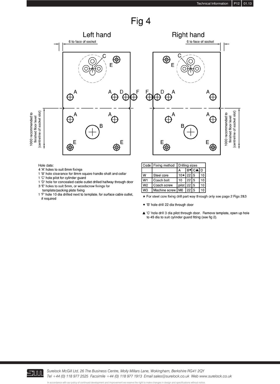
11 P10 SF-8785 Fixing instructions AC800 lock rim cylinder. Outward opening Fixing Instructions This device is for outward opening doors. All dimensions are nominal and in mm unless otherwise stated. Fit socket flush into frame as shown on page 11 Fig 3, at the required height, (recomended 1000mm from finished floor/sill level to centre of socket slot), clear bolt slot to allow for bolt engagement. Position and screw template accurately to door using dimensions indicated on page 12 Fig 4. Determine which fixing method to use, steel cores, coach bolts, coach screws or machine screws (check orientation for steel cores). Drill holes in door to suit, see page 12 drilling data. While template is removed, clear surface cable pathway, if required. Refit template as mounting plate for lock. Fit cylinder guard and cylinder if required (see page 11 fig 2). Cut cylinder operating tang to engage lock as shown. Fit lock and cable access cover to door using chosen fixing method, cores, coach bolts, etc. Location with template is enabled with dowel pins fitted to lock body. Measure and cut outside handle shaft to length and fit outside handle to door surface, if required (see page 11 fig 2). Note: it is advisable to check the operation of the lock using the outside handle before fitting the rose cover, as the cover is difficult to remove without damage. Tools required: Screw drivers various pozi drive Electric or hand drill Drills/boring bits dia 3, 5, 10, 16, 22, 45 Pilot drill for 8mm coach screw Pilot drill for No.10 wood screw Allen/Hex keys 2.5mm & 3mm Chisel for socket fitting Maintenance instructions It is recommended that the following routine maintenance checks be undertaken at: Monthly intervals: Inspect and operate the lock to ensure that all components are in a satisfactory working condition. Ensure socket is free from obstruction and is in line with bolt. Check that all fixing screws are in place and tight. Lubricate cylinder (if applicable) with an appropriate manufacturers lubricant (not oil), available from Surelock McGill. Annually or 50,000 cycles (which ever is sooner): The equipment should be serviced by a Surelock McGill trained engineer. Any item noted to have excessive wear should be replaced.
. Drill holes in door to suit, see page 12 drilling data.")
12 P11

13 P12
14 P13 SF Fixing instructions. LEO (surface mounted) LEO module dimensions are given in Fig. 1. Centre module and LEO fixing holes should be drilled using template provided and as described in the device fixing instruction. Assemble LEO to door as follows. 1. Countersink or counter bore four fixing holes as appropriate on inside face of door and counter bore 30mm dia relief hole in outer face to accept LEO boss as shown in Fig Offer LEO to external face of door and secure with four M8 screws provided. Use reinforcing collars on timber doors - see Fig Continue with instructions for System A or System B as appropriate. SYSTEM A (Fig. 3) 1. Cut square handle shaft to length (opposite end to tapped hole). The shaft should penetrate the LEO boss 8 to 10mm. Cutting shaft flush with surface of door will give 10mm penetration of the boss when LEO is mounted on door surface. 2. Pass square shaft through centre module, assemble handle on to shaft and fix with screw provided. 3. Continue by assembling system to door in accordance with the instructions provided. SYSTEM B (Fig. 4) 1. Cut square drive shaft to length. Shaft should penetrate LEO boss by 8 to 10mm. Cutting shaft flush with surface of the door will give 10mm penetration of LEO boss when LEO is mounted on door surface. 2. Continue by assembling system to door

15 P14

16 P15 Wiring example (refer to specific wiring diagram for each product) BOLT STATUS MICROSWITCH OPTION M LOCK STATUS MICROSWITCH OPTION N SOLENOID LOCK RELEASE OPTION R Notes 1. if option M (bolt monitoring) is fitted without option N (deadlock monitoring) then red, green and blue cores are used. 2. If only a solenoid is fitted (option R) black and yellow are replaced with red and blue. Solenoid Power Consumptions Product Option Code Solenoid voltage (V d.c.) Power consumption (W) Current draw (A) Slimline R R R R R R Stirling R R R R R R S R R Cable loop capacities Max cable diameter Cable capacity 7/0.2mm Cable capacity 16/0.2mm S-8412 Cable loop.surface 8mm 20 core 6 core S-8419 Cable loop.concealed 6mm 8 core 3 core

17 Maintenance instructions Technical Information P16 1. It is recommended that the following routine maintenance checks be undertaken at monthly intervals: Inspect and operate the panic/emergency device to ensure that all components are in a satisfactory working condition; using a force gauge, measure and record the operating forces to release the exit device. Date Door Ref. Force Initials Operating forces (installer to record operating force at row 1) Ensure that all keepers (sockets) are free from obstruction. Check that all fixing screws and retaining pins are in place and tight, and that the equipment is correctly adjusted. Lubricate cylinders (if applicable) with an appropriate manufacturers lubricant (not oil), available from Surelock McGill. Ensure that the bolts are in line with keeps (sockets). Ensure restraint is operating correctly and adjust if required. Check periodically that no additional locking devices have been added to the door since its original installation. Check periodically that all components of the system are still correct in accordance with the list of approved components originally supplied. Check periodically that the operating element is correctly tightened and, using a force gauge, measure the operating forces to release the exit device. Check that the operating forces have not changed significantly from the operating forces recorded when originally installed. 2. Annually or 50,000 cycles (which ever is sooner): Surelock McGill trained engineer should service the equipment. Any item noted to have excessive wear should be replaced.
 Ensure that all keepers (sockets) are free from obstruction.")
18 P17 Peak Permissible Blast Loads The following schedule is a guide only of Peak Permissible Blast Loads calculated for a range of door sizes secured with a varied number of bolts and differing materials. The assessments for each door and bolt configuration are based on a number of assumptions, such that the figures should be used for guidance only, it is assumed that: n n n The load is distributed equally (50/50) between the hinge side and the leading edge of the door The hinge and door frame is capable of resisting the applied load The door leaf is substantially stiff such that the load is transmitted directly to the support points (ie. hinge on one side and bolts on the other) n n n The load is evenly distributed on all bolts and the position of the horizontal bolt has no effect on load distribution - in a normal door design we have considered that the horizontal bolt would take load from half of the door area above and below in a 3-bolt group. The top and bottom bolts would therefore receive half the load applied to the central bolt, with the central bolt being the limiting factor The blast load is limited by the shear capacity of one bolt - therefore the total allowable blast load is factored by the number of bolts These figures are the ultimate capacities, with an allowance for dynamic load factors Door Schedule - Permissable Peak Blast Loads (kn/m 2 ) Bolt Diameter Metric Imperial Door 2500mm x 1000mm (8 2 x 3 3 ) Fitted with 2 vertical bolts Fitted with 2 vertical bolts plus 1 horizontal Mild Steel Stainless Steel EN24T Mild Steel Stainless Steel EN24T mm 20mm 25mm 40mm Bolt Diameter Metric Imperial Door 3000mm x 1250mm (9 10 x 4 1 ) Fitted with 2 vertical bolts Fitted with 2 vertical bolts plus 1 horizontal Mild Steel Stainless Steel EN24T Mild Steel Stainless Steel EN24T mm 20mm 25mm 40mm Bolt Diameter Metric Imperial Door 4000mm x 1500mm (13 1 x 4 11 ) Fitted with 2 vertical bolts Fitted with 2 vertical bolts plus 1 horizontal Mild Steel Stainless Steel EN24T Mild Steel Stainless Steel EN24T mm 20mm 25mm 40mm The above table is a guide to the permissible Peak blast loads a device could provide, this is of course dependant on the complete door and frame design, the method of fitting, including the hinge side of the door.
 between the hinge side and the leading edge of the door The hinge and door frame is capable of resisting the applied load The door leaf is substantially stiff such that the load is")
19 P18 Surelock Hinge Loading The following chart is a guide for maximum door sizes and weights and a door height of 2.2 metres using three hinges equally spaced. Surelock Hinge loading Chart Refer to Surelock McGill technical department Use HA8 hinges Use HA7 hinges Use HA6 hinges Fixings are not supplied with hinges and need to be selected for suitability of door and frame material, construction and loadings. Please refer to our technical department for any further assistance. +44 (0)

WHI 90-Minute Rated Veneered Door Frame Installation Instructions
 No. 940-03-10 INSTALLATION INSTRUCTIONS 90 MINUTE RATED VENEERED DOOR FRAME DOOR REQUIREMENTS: Consult the door manufacturer to make sure that the doors are qualified for the hardware to be installed,
INSTALLATION AND OPERATING INSTRUCTIONS For Model GL1 Gate Locks
 Securitron Magnalock Corp. www.securitron.com ASSA ABLOY, the global leader Tel 800.624.5625 [email protected] in door opening solutions INSTALLATION AND OPERATING INSTRUCTIONS For Model GL1 Gate
SECTION G2: CABLE PROCESSOR MODULE MAINTENANCE
 SECTION G2: CABLE PROCESSOR MODULE MAINTENANCE Cable Processor Module overview WARNING! When tipping the Cable Processor Module back, (after removing the toggle arm pin), use extreme caution not to drop
DE Frame with C Series Sidelight
 TOOLS REQUIRED Tape measure 6' magnetic level 3' magnetic level Screw gun with clutch adjusted #2 phillips tip #3 phillips tip Screwdriver (used to adjust frame on will using oval slots) Pry Bar Powder
ISSUE 2. Installation Guide
 ISSUE 2 Installation Guide Here at Slide and Fold, we LOVE our Bi-Fold Plus range of folding-sliding doors. We want to ensure that your customers love them too. So we have created a new, detailed installation
Lathe Milling Attachment
 Lathe Milling Attachment By L C. MASON BY CLEVERLY stacking cold-rolled flat stock together, T-slots and slide for this lathe milling attachment are made without costly machinery. In fact, only two tools,
PHA 2000 PHB 3000 EXIT PAD
 PHA 2000 PHB 000 EXIT PAD Panic Hardware in Contur Design PHA 2000 PHB 000 EXIT PAD THE MODULAR PANIC HARDWARE-SSTEM IN CONTUR DESIGN Prior knowledge of how to open the escape door is not expected. DANGER
Technical data sheet PVC Bi-fold doors
 Standard Specifications White internally beaded, Deceuninck 3000 series profile 28mm Low-e toughened sealed units with argon gas Open in doors with white handles and hinges Tracks are fitted to the top
Wiper Motor Marinco 2.5. Installation Instructions
 Wiper Motor Marinco 2.5 Installation Instructions Wiper Motor Marinco-2.5 The Marinco 2.5 Wiper Motor Offers the Following Features: Fully sealed base and housing which allows installation in outdoor wet
AMS 120. EFT Guest Card Terminal & Refund unit
 AMS 120 EFT Guest Card Terminal & Refund unit ACCOUNT MANAGEMENT STATIONS Wall mounted kiosk offering Visitor card purchase and refund Card deposit EFT purchase, refund and loading Full statement facilities
POSEIDON 2-29, 2-25 & 2-22 POSEIDON 2-29, 2-25 & 2-22 XT
 POSEION 2-29, 2-25 & 2-22 POSEION 2-29, 2-25 & 2-22 XT Repair Manual Index A. Safety precautions 3 B. Technical data 4 C. Structure 5-6. Service / Repair 7-23 E. Tools 24 F. Function 25-26 G. Electric
CLEAR-DIVISIONS CENTERFOLD
 CLEAR-DIVISIONS CENTERFOLD Introduction: The following three (3) part specification offers the Standard and Optional features for the CLEAR-DIVISIONS CENTERFOLD moveable The yellow highlighted areas in
PREASSEMBLED ELEMENTS FOR LIFTING AND SLIDING DOORS
 SYSTEM COMPONENTS PREASSEMBLED ELEMENTS FOR FIFTING AND SLIDING DOORS s r ood gn i d i l s dna gn i t f i f r o f s t neme l e de l bme s s ae r P PREASSEMBLED ELEMENTS FOR LIFTING AND SLIDING DOORS These
CATALOGO PRODOTTI PORTONI INDUSTRIALI COIBENTATI
 CATALOGO PRODOTTI PORTONI INDUSTRIALI COIBENTATI The Company Founded in 1973 by Mr Imes Tinti in association with his son Vanni Tinti. In 1999 the locksmith workshop became a modern industrial company
TS93 EMR T/PT/TDE. Surface applied door closer
 TS EMR T/PT/TDE Surface applied door closer Installation instructions: Pull side track mount door closer with smoke detector (EMR T) Push side track mount door closer with smoke detector (EMR PT) Double
C O N V E Y O R C O M P O N E N T S C H A I N S B E L T S B E A R I N G S
 C O N V E Y O R C O M P O N E N T S C H A I N S B E L T S B E A R I N G S January 2009 Issue 6 Valu Guide Brackets The Ultimate in Adjustability and Cost Savings Valu Guide brackets are part of a family
Machine devices, jig devices
 Machine devices, jig devices 853 K0697 Rolled thread studs DIN 6379 Material: Tempered steel. KIPP Rolled thread studs DIN 6379 Order No. D L B1 B2 Approx. weight g Surface finish: Thread rolled. Class
CLEAR-DIVISIONS VARIOFOLD
 CLEAR-DIVISIONS VARIOFOLD Introduction: The following three (3) part specification offers the Standard and Optional features for the CLEAR-DIVISIONS VARIOFOLD moveable The yellow highlighted areas in the
Electro-Pneumatic Bus Door Control Mechanism
 Electro-Pneumatic Bus Door Control Mechanism Application and Feature 1. Pneumatic Door Mechanism actuates the open/close movements of bus door through two double acting cylinders and two linkages with
Slide the new steering column shaft through the steering column from the driver compartment.
 Slide the new steering column shaft through the steering column from the driver compartment. Push the column shaft through the steering column until the machined end is out past the column lower bushing.
Narrow stile lock 1314
 3 2 4 6 6 1 3 2 4 4 5 3 2 4 3 5.... ( (. ). ) 11 12 5 3 5 4 8 1 6 20 8.5 6.5 19 Backset 15 3 5 2 1 5 2 5 5 0 8 9 2 8 1 1 21-1mm 12 8 24 1 6 8 1 ( 9 2 5 ) ) ). ) Narrow stile lock 1314 CE EN 12209 2 4 5
SELF-STEERING AXLE TABLE OF CONTENTS
 SELF-STEERING AXLE TABLE OF CONTENTS Section 1 - Introduction Section 2 - Pre-Installation Check List Section 3 - Ride Height Adjustments Section 4 - Suspension Mount Section 5 - Axle Mount Section 6 -
K. D. FRAME ASSEMBLY FOR CLOSED STEEL STUD WALLS...Ins 10. FRAME INSTALLATION DETAILS FOR CLOSED STEEL STUD WALLS...Ins 11
 K. D. FRAME ASSEMBLY FOR MASONRY WALLS...........................Ins 2 FRAME INSTALLATION DETAILS FOR MASONRY WALLS......................Ins 3 INSTALLING EXISTING MASONRY WALL ANCHORS IN FRAME..................Ins
Installation guide for the SafeLine type anchorage device. Tested in compliance with EN 795: 1996. No.: SE-...
 Installation guide for the SafeLine type anchorage device Tested in compliance with EN 795: 1996 No.: SE-... Version: 09.10.2008 SE 67 Subject to technical alterations! Contents 1. General information
2&3 SECTION LOFT LADDER
 TWIST CATCH ASSEMBLY A4 A2 A1 A3 A7 A6 A5 2&3 SECTION LOFT LADDER Images feature the 3 section loft ladder, but the same instructions apply to both 2 & 3 section ladders Installation and Operating Instructions
SECTION 6. Glass Storefront Doors:
 SECTION 6 Glass Storefront Doors: Table of Contents 3070 Storefront Door System Description & Dimensions 6070 Storefront Door System Description & Dimensions Door Leaf Detail Optional 10 Bottom Rail Detail
INSTRUCTIONS: LocknCharge Laptop Carts
 INSTRUCTIONS: LocknCharge Laptop Carts www.lockncharge.com Extra Tools required: Hammer, Philips head screwdriver, medium adjustable spanner. (Allen key supplied) (Panel colours for illustration purposes
Detector transparent with Color Inserts. FAA 500 TR P Trim Ring transparent with Color Inserts. FCA 500 / FCA 500 E Detector Bases
 Detector Color Detector transparent with Color Inserts FAA 500 TR W Trim Ring FAA 500 TR P Trim Ring transparent with Color Inserts FAA 500 BB Ceiling Mount Back Box FCA 500 / FCA 500 E Detector Bases
ABLOY EXIT. Functional and technical descriptions Single and double leaf doors. An ASSA ABLOY Group brand
 SSFN 014/2 2 ABLOY EXIT Functional and technical descriptions Single and double leaf doors An ASSA ABLOY Group brand ABLOY EXIT - EXIT PRODUCTS It is time to take the exit safety standards to a new level.
Awning Instructions. Standard Manual 1.5m to 4.5m
 Awning Instructions Standard Manual 1.5m to 4.5m English Standard Manual Instructions Contents Warning 1.5m 3.0m Awnings 4 x Expansion bolts (2 per bracket)** 2 x brackets 1 x Awning 1 x Winder handle
Wren Kitchens Installation Tips... 3. Carefully check your kitchen delivery... 4. Measuring out and marking up... 5. Fitting the base cabinets...
 tra 1 Index Wren Kitchens Installation Tips... 3 Carefully check your kitchen delivery... 4 Measuring out and marking up... 5 Fitting the base cabinets... 6 Fitting the corner cabinets... 7 The 972mm or
K17.11 DOOR BOLTS K17 DOORS 01.09.2013
 K17 DOORS K17.11 01.09.2013 Waregemstraat 5-9870 Zulte - Belgium - T. +32 9 388 88 81 - F. +32 9 388 88 21 - [email protected] - www.sobinco.com CONTENTS 1. Locking set series 86000...K17.11.03 2.
Operating Instructions Drill rig DRU160
 Operating Instructions Drill rig DRU160 Index 000 / 001 Original operating instructions 10988825 en / 20.10.2009 Congratulations! With a Hydrostress unit from TYROLIT you have chosen a tried and tested
UB1 AIR CONDITIONING UNIT INSTALLATION INSTRUCTIONS
 UB1 AIR CONDITIONING UNIT INSTALLATION INSTRUCTIONS INSTALLATION INSTRUCTIONS: Carefully read these instructions before installing your new air-conditioner. AUSTRALIAN AUTOMOTIVE AIR AL00500054E 1 Table
Residential Garage Door Terminology
 A Air Infiltration: The leakage or passage of air through a door system Anodize: A hard non-corrosive oxide film on the surface of aluminum Astragal: A compressible or deformable seal provided on the bottom
Sliding and Folding Door Fittings Sliding Door Accessories
 Sliding door lock Toplock For 1- and 2-leaf sliding doors Suitable for toughened safty glass and laminated sheet glass Suitable for DIN left and DIN right Max. weight per door leaf 120 kg For glass thickness:
Combi B Alarm box. Mounting instructions
 Combi B Alarm box Mounting instructions EN Mounting instructions Alarm box Combi B VdS, G113064, G113065, G113066 Table of Contents 1 Description... 3 2 System overview... 3 3 Structure... 3 3.1 Power
TABLE OF CONTENTS. I. TROUBLESHOOTING... 2 - Section 1.01: Common Problems/Solutions... 2
 BAL Accu-Slide System I. Table of Contents TABLE OF CONTENTS I. TROUBLESHOOTING... 2 - Section 1.01: Common Problems/Solutions... 2 II. GETTING STARTED... 5 - Section 2.01: Tools You Will Need... 5 - Section
GEH6290. Mechanism Circuit Breaker. Handle Operating Mechanism Cat. No. Type NEMA 1, 3R, 12, 13 NEMA 4/4X Cat. No. Cat. No. Series Instruction
 GEH6290 g Cable Operator Mechanisms for E150, SE150, SF250, and SG600 Spectra RMS Circuit Breakers Type SCH1/1X, SCH2/2X Flange-Mounted Handle Assemblies, Cable Series SC3L SC10L and Type SC0M1A, SCOM1EF,
How To Replace A Reverse Osmosis Water Tank
 ALL MODELS REVERSE OSMOSIS WITH NONAIRGAP FAUCET 1. Read all instructions carefully before starting installation. 2. Find the cold water line beneath your sink. The cold water is typically on the right.
Security steel door dw 52-1 Teckentrup DF WK 2 optionally with glazing/ventilation grille
 Security steel door dw 52-1 Teckentrup DF WK 2 optionally with glazing/ventilation grille Text example Compile and tender according to requirements. Please refer to technical data below for respective
Flue Installation. High Efficiency Condensing Boilers
 Flue Installation High Efficiency Condensing Boilers Table of contents INTRODUCTION 1 Instruction guidance...4 1.1 Product documentation...4 1.2 Explanation of symbols...4 1.3 Important Notes...4 INSTALLATION
All-Season Sunroom Sliding Glass Door Installation Instructions
 ASRESGD-08 All-Season Sunroom Sliding Glass Door Installation Instructions Panel Frame Door Frame Left Side Foam Insulator IE241 H Bar Assembly Door Frame Top Track Panel Frame Door Frame Right Side Stationary
K17.12 Door closers K17. Doors 01.09.2013
 K17 Doors K17.12 01.09.2013 Waregemstraat 5-9870 Zulte - Belgium - T. +32 9 388 88 81 - F. +32 9 388 88 21 - [email protected] - www.sobinco.com Contents 1. OPTIC door closer TS40(V) with scissor
LockerLock Schließgehäuse LockerLock lock case Boîtier de fermeture LockerLock Scatola di ciusura LockerLock Caja de cierre LockerLock
 LockerLock Schließgehäuse LockerLock lock case Boîtier de fermeture LockerLock Scatola di ciusura LockerLock Caja de cierre LockerLock Caution! Õ It is necessary to read the section "Commissioning" in
These instructions will show you how to install an internal door into a non-loadbearing partition wall. The instructions are split into three parts.
 No 8 in the series of 'How to' brochures produced by PlaceMakers, New Zealand How to Frame and Hang a Door These instructions will show you how to install an internal door into a non-loadbearing partition
HARDWARE STANLEY ARCHITECTURAL HARDWARE
 HARDWARE STANLEY ARCHITECTURAL HARDWARE STANLEY ARCHITECTURAL HARDWARE TABLE OF CONTENTS Page Company history...2 Wardrobe pivots...3, 4 Cabinet hinges... Cabinet pulls..., 6 Cabinet knobs...6 Cabinet
BUILT-IN DISHWASHER INSTALLATION INSTRUCTIONS
 BUILT-IN DISHWASHER INSTALLATION INSTRUCTIONS PLEASE READ COMPLETE INSTRUCTIONS BEFORE YOU BEGIN LEAVE INSTALLATION INSTRUCTIONS AND USER'S GUIDE WITH OWNER ALL ELECTRIC WIRING AND PLUMBING MUST BE DONE
ROLLING CURTAIN DOOR INSTALLATION, MAINTENANCE & PARTS MANUAL WINDLOCK MODEL 955WL
 ROLLING CURTAIN DOOR INSTALLATION, MAINTENANCE & PARTS MANUAL WINDLOCK MODEL 955WL Read manual thoroughly prior to installing door. Rolling steel doors are large, heavy objects that move with the help
CONTENTS 1. INTRODUCTION...1 2. METHODOLOGY...2 3. RESULTS & FINDINGS...9 APPENDIX
 Load Testing of Balustrade Systems Test Report No. S365 CONTENTS 1. INTRODUCTION...1 2. METHODOLOGY...2 2.1 BALUSTRADE LOAD ASSESSMENTS... 2 2.2 TEST SYSTEMS... 3 2.3 TEST PROCEDURE... 8 3. RESULTS & FINDINGS...9
TECHNICAL INFORMATION
 TECHNICAL INFORMATION Models No. 2012NB Description 304mm (12") Automatic Thickness Planer CONCEPTION AND MAIN APPLICATIONS * Compact and light weight (27 Kg./59 lbs) automatic thickness planer for easier
Machine Screws, Dowel Pins and Hardware
 Machine Screws, Dowel Pins and Section Contents Plain Socket Head Screws...Page 13-2 Wire Locking Screws...Page 13-3 Captive Screws...Page 13- Ventilation Screws...Page 13- Shoulder Screws...Page 13-
CELO5. User & Installation Manual. www.audac.eu
 CELO5 User & Installation Manual www.audac.eu 2 Introduction 5 High-end Slim Ceiling Speaker The CELO5 is the 5 version of AUDAC s CELO High-end Slim ceiling speaker series with an RMS power of 50 Watt
Installation Instructions
 Installation Instructions 1. Position the unit onto bridging packers. These keep the unit away from any water sitting inside the frame. 2. Centralise the unit within the frame and pack the edges with appropriate
INSTALLATION INSTRUCTIONS FOR MODEL 1560 AND 1570 ELECTRIC TRIM CONTROL FOR USE WITH CORBIN 955 AND YALE 626F HEAVY DUTY TRIM
 II E1500-8 INSTALLATION INSTRUCTIONS FOR MODEL 1560 AND 1570 ELECTRIC TRIM CONTROL FOR USE WITH CORBIN 955 AND YALE 626F HEAVY DUTY TRIM FUNCTION DESCRIPTION 1560 FAIL SAFE LEVER IS LOCKED WHEN POWER IS
STEEL-RITE II or III COMMERCIAL SECTIONAL DOOR Owner s Manual Supplement Model 52242 NOTICE TO USER
 STEEL-RITE II or III COMMERCIAL SECTIONAL DOOR Owner s Manual Supplement Model 52242 NOTICE TO USER Thank you for purchasing the Steel-Rite II or III, model 52242 commercial sectional door from RITE-HITE
Slides and Drawers. The right collection
 Slides and Drawers The right collection 1Technical Details Drawer Runners Carrying capacity Kg. Static load Dynamic load Pag. 01 Concealed Runners Excel N Excel N Excel N Excel N650 Excel N Excel PlugIn,
INSTRUCTION MANUAL HYDRAULIC GATE TRANSMISSION SYSTEM ECO240-ECO360
 INSTRUCTION MANUAL HYDRAULIC GATE TRANSMISSION SYSTEM ECO240-ECO360 IMPORTANT SAFETY INSTRUCTIONS WARNING! To reduce the risk of injury or death it is important to closely follow all of the following instructions.
Installation Instructions K900 series Door Closer
 Installation Instructions series Non-Hold Open Models Adjustable size : 1(BF) thru 6 Optional Feature : Delayed Action An Incorrectly installed or improperly adjusted door closer can cause property damage
AVENTOS HF Wood / wide aluminum door application
 AVENTOS HF Wood / wide aluminum door application Lift mechanism set Lift mechanism (qty 2) #7 x 35 mm (-3/8 ) wood screw (qty 0) Power factor 85 230 ( lift mechanism req.) 20F2200.N5 23 470 20F2200.N5
I BEAM TRACK INSTALLATION
 PDQ 0/700 FESTOON SYSTEM INSTALLATION AND MAINTENANCE INSTRUCTIONS INTRODUCTION The PDQ Festoon System was designed to run on one of three sizes of I-beams: S x., S8 x 8. and S x.. System trolleys must
KTC Keyless Entry System
 Thank you for purchasing the Snap-on KTC Keyless Tool Control System. The information contained in these instructions is intended to serve as a guide so as to allow the electronic lock feature to be quickly
POWER LOCK KIT GENERAL INSTALLATION -J04427 REV. 2007-12-04. Kit Number. Models. Additional Parts Required. Kit Contents
 -J0 REV. 00--0 POWER LOCK KIT GENERAL Kit Number -0, 0-0 Models For model fitment information, please see the P&A Retail Catalog or the Parts and Accessories section of www.harleydavidson.com (English
OLI. Oil level indicator
 OLI Oil level indicator Oil level indicator Unexpected or accidental oil leakages may occur randomly along transformer s lifetime. Clear indication of oil level inside transformer tank and on load tap
Parts#MB003-003 Reverse Gear MAMBA (Monoblock for Cable operated) For 5 speed Trans., '87 to '06 Big Twin models (except '06 Dyna)
 For 5 speed Trans., '87 to '06 Big Twin models (except '06 Dyna)") Installation Instructions Reverse Gear MAMBA (Monoblock for Cable operated) Read and become familiar with these installation instructions before start. Two Piece for H-D 5 Speed Trans., Cable operated
Installation Instructions Reverse Gear MAMBA (Monoblock for Cable operated) Read and become familiar with these installation instructions before start. Two Piece for H-D 5 Speed Trans., Cable operated
Awning Instructions. Full Cassette 1.5m to 6m
 Awning Instructions Full Cassette 1.5m to 6m English Full Cassette Manual & Electric Instructions Contents Warning 1.5m - 3.5m Awnings 8 x Expansion bolts ** 2 x brackets 1 x Awning 1 x Winder 4.0m -
DIAMOND Retractable Rodding Robot Model SPRAYROD-R
 2004-12-21 2 1 (23) DIAMOND Retractable Rodding Robot Model SPRAYROD-R 2004-12-21 2 2 (23) Table of contents 1 TECHNICAL DESCRIPTION...4 1.1 MAIN DETAILS...5 1.2 COMPONENTS DESCRIPTION...5 1.2.1 Pneumatic
RadianceRail Installation Guide
 RadianceRail Installation Guide Installing RadianceRail with CableRail by Feeney... 2 Installing CableRail by Feeney for RadianceRail... 7 Installing RadianceRail Stairs with CableRail by Feeney... 10
VOYAGER 570G. 744A Sprayer Control
 VOYAGER 570G 744A Sprayer Control U S E R M A N U A L U S E R M A N U A L Table of Contents CHAPTER 1 - INTRODUCTION...1 SYSTEM CONFIGURATIONS...1 KIT CONTENTS...3 CONTROL HOUSING ASSEMBLY...5 CHAPTER
Heavy Duty Solenoid Controlled Access Lock. User Manual - Original Language Version
 OLYM-S24D-C24D The Olympus 4HD is a heavy duty solenoid controlled access lock available with either a stainless steel tongue actuator or a heavy duty handle. The Olympus 4HD is capable of supporting Category
Power Window/Power Lock Installation. To begin with you will need all the parts listed below:
 Power Window/Power Lock Installation To begin with you will need all the parts listed below: From Donor Fiero: Fiero power window regulators Power window motors (Generic GM type part) -motors are riveted
Cable Drum Installation
 20 Cable Drum Installation COUNTERBALANCE None Shake the TorqueMaster spring tube gently to extend the winding shafts out about 5" on each side. For single spring applications, there will be no left hand
Installation Guide. WSD-100 Wind Speed and Direction Sensor For XR5 Data Loggers. February, 2011
 WSD-100 Wind Speed and Direction Sensor For XR5 Data Loggers Installation Guide February, 2011 Pace Scientific Inc www.pace-sci.com Tel: 704-799-0688 [email protected] 1 Disclaimer The following warranty
Digital Fingerprint safe
 Digital Fingerprint safe Model 96846 Operation Instructions Diagrams within this manual may not be drawn proportionally. Due to continuing improvements, actual product may differ slightly from the product
Rebuild Instructions for 70001 and 70010 Transmission
 Rebuild Instructions for 70001 and 70010 Transmission Brinn, Incorporated 1615 Tech Drive Bay City, MI 48706 Telephone 989.686.8920 Fax 989.686.6520 www.brinninc.com Notice Read all instructions before
Shunt lock function 3066
 Version: January 2004 Contents Alarm System Activation unit Deactivation unit Digital locking cylinder or Smart Relay 1.0 Method of Operation 4 1.1 General 4 1.2 Turning the Alarm System On 4 1.3 Turning
Variety of Control Options Control is possible via wall switches, remote control systems or integration into building management systems.
 Breezway Altair Powerlouvre Window 35 Breezway Altair Powerlouvre Window The Powerlourve Window motor is neatly concealed within the Easyscreen TM Frame or the Component Powerlouvre Head Section. Automated
Fabrication Illustration Part No. Description Door Frame. P092 Mortised Butt Hinge P092D P092F (includes P2092 $ 48 $ 21 frame/door reinforcing)
") Custom Blank Entrances - Applied Hardware & Preps - Tubelite Standard Hardware Butt Hinges Pivots C2 Page 1 P092 Mortised Butt Hinge P092D P092F (includes P2092 $ 48 $ 21 frame/door reinforcing) P795S
Custom Blank Entrances - Applied Hardware & Preps - Tubelite Standard Hardware Butt Hinges Pivots C2 Page 1 P092 Mortised Butt Hinge P092D P092F (includes P2092 $ 48 $ 21 frame/door reinforcing) P795S
Vinyl Brick Mould Field Installation Instructions All Vinyl and Vinyl Clad Windows
 Vinyl Brick Mould Field Installation Instructions All Vinyl and Vinyl Clad Windows Viewed from the exterior. IMPORTANT: Please read before you begin installation. TABLE OF CONTENTS AND TOOL / MATERIAL
CI/SfB. (31.59) X NOVEMBER 2003 Coburn Interior Sliding Systems
 X NOVEMBER 2003 Coburn Interior Sliding Systems") Uniclass L4181 EPIC D181 CI/SfB (31.59) X NOVEMBER 2003 Coburn Interior Sliding Systems Interior Sliding Door Gears FOR CUPBOARDS, WARDROBES, INTERIOR SLIDING AND FOLDING DOORS A comprehensive range of
Uniclass L4181 EPIC D181 CI/SfB (31.59) X NOVEMBER 2003 Coburn Interior Sliding Systems Interior Sliding Door Gears FOR CUPBOARDS, WARDROBES, INTERIOR SLIDING AND FOLDING DOORS A comprehensive range of
Premier & Deluxe 3-Season Room Sliding Glass Door
 DTSSGD-11 Premier & Deluxe 3-Season Room Sliding Glass Door Installation Instructions Screen Door Seal Left Side Track Top Track Assembly Right Side Track Right Side Trim Sliding Glass Door Sliding Screen
Rollers. from the UK s largest roller manufacturer. Quality Performance Reliability
 Rollers from the UK s largest roller manufacturer Quality Performance Reliability 42 Index Gravity Rollers Light to Medium Duty 4 Heavy Duty 5 Plastic Rollers 6 Stainless Steel Rollers 7 Grooved Rollers
SIMRAD SD10 Sailboat Drive
 INSTALLATION MANUAL SIMRAD SD10 Sailboat Drive 20222683/A English Simrad SD10 Sailboat Drive About this document Rev. A First issue 2007 Navico AS. All rights reserved. No part of this work covered by
-1- SPECIFICATIONS 002085 CONE SETTER PLATFORM ATTACHMENT INDEX
 -1-002085 CONE SETTER PLATFORM ATTACHMENT INDEX I. GENERAL EQUIPMENT : A. Intent Statement B. Cone Setter Platform II. III. 1. Understructure Frame 2. Mounting Components 3. Paint 4. Basket 5. Labels 6.
Saferand easierinstallation
 EN 85-07 Saferand easierinstallation IföSigninstallationsystem andifösignbuilt-incistern www.ifosanitar.com/sign Aneffectivesolution withmanyadvantages. Ifö Sign installation system makes life a little
CERTIFICATE OF APPROVAL No CF 291 SCHOTT UK LIMITED
 CERTIFICATE OF APPROVAL No CF 291 This is to certify that, in accordance with TS General Requirements for Certification of Fire Protection Products The undermentioned products of Drummond Road, Stafford.
Single sub-base valve
 solenoid valves Mini-valves 10 mm Electrical connection... Mounting... Port sizes... Rated temperature... Fluid... Working pressure... Nominal flow... Pneumatic connections Voltage... Power... NC poppet
SPECIFICATIONS FOR BOON EDAM TOMSED MODEL TUT-65TMB
 SPECIFICATIONS FOR BOON EDAM TOMSED MODEL TUT-65TMB PRODUCT DESCRIPTION: BOON EDAM TOMSED MODEL TUT-65TMB STAINLESS STEEL BARCODE SCANNING ELECTRONIC REGISTERING TURNSTILE SCOPE OF OPERATION: A. The TUT-65TMB
IN00419 (rev A) Aqua 6 Glide Quadrant and Off-set Quadrant Enclosure
 Aqua 6 Glide Quadrant and Off-set Quadrant Enclosure") IN00419 (rev A) Aqua 6 Glide Quadrant and Off-set Quadrant Enclosure Instruction suitable for both Quadrant & Off-set Quadrant variations. Instruction suitable for both Right and Left Hand fixing variations
IN00419 (rev A) Aqua 6 Glide Quadrant and Off-set Quadrant Enclosure Instruction suitable for both Quadrant & Off-set Quadrant variations. Instruction suitable for both Right and Left Hand fixing variations
Sash Replacement Guide
 for Andersen 200/400 Series Awning Windows Read all instructions carefully before attempting this procedure. If you have any questions about your ability to complete this procedure, call Andersen at 1-888-888-7020
AZEK Rail Install Guide
 TRIM MOULDING DECK PORCH RAIL PAVERS AZEK Rail Install Guide Installing AZEK Rail with CableRail by Feeney... 1 Installing CableRail by Feeney for AZEK Rail... 7 Installing AZEK Rail Stairs with CableRail
Attachment of supporting fitting components for turn-only and tilt&turn fittings
 Gütegemeinschaft Schlösser und Beschläge e.v. : TBDK ORIGINAL VERSION Version: 2014-05-05 with definitions for turn-only and tilt&turn fittings and their possible installation positions Contents 1 Forward...3
HMMA 830 HARDWARE SELECTION FOR HOLLOW METAL DOORS AND FRAMES HOLLOW METAL MANUAL -02 NAAMM STANDARD METAL DOORS & FRAMES NAAMM 01 NAAMM 01
 HOLLOW METAL MANUAL NAAMM STANDARD HMMA 830-02 METAL S & FRAMES 8d NAAMM 01 02 HARDWARE SELECTION FOR HOLLOW METAL S AND FRAMES NAAMM 01 02 8d METAL S & FRAMES A Division of HOLLOW METAL MANUFACTURERS
Installation Instructions For Slider Casement Air Conditioners
 Installation Instructions For Slider Casement Air Conditioners NOTE: These instructions describe installation in a typical wood framed window with a wood SLIDE-BY sash, or installation in a metal CASEMENT
Integral Kit Instructions
 Integral Kit Instructions For Fisher & Paykel Cabinet widths of 525, 635, 680, 790 mm wide For curved door Models Series B, C, D & G Manual 814980 Updated August 2008 IMPORTANT If your refrigerator has
DORMA ED 800 SERIES Service Manual
 DORMA ED 800 SERIES Service Manual ED 800J ED 800T software level 3.27M www.dorma-usa.com 1-800-523-8483 INSPK NO. 08280020 Rev.08/07 08280021 08/07 TABLE OF CONTENTS Page Status Light...3 Status Light
STEWART GILL CONVEYORS Ltd
 STEWART GILL CONVEYORS Ltd 550M STS SYSTEM overhead - inverted - side mounted - floor mounted - SPECIALISTS IN OVERHEAD CONVEYOR SYSTEMS 2 Index About 550M STS... 3 Track... 4 Track Supports... 5 Bends...
RAIL FREE SOLAR ROOF MOUNT
 RAIL FREE SOLAR ROOF MOUNT Utilizes EcoFasten Solar s patented technology Rock-it system Designed with the installer in mind. EcoFasten Solar specializes in solar roof attachments that are the easiest
Beautifully Traditional
 Arcade 800mm Single Sliding Door Quadrant - nickel Arcade 900mm Single Sliding Door Quadrant - nickel ARC48 ARC49 INSTALLATION INSTRUCTIONS A www.arcadebathrooms.com IMPORTANT - Please read before installation
EVC40 EMERGENCY VOICE COMMUNICATION SYSTEM
 EVC40 EMERGENCY VOICE COMMUNICATION SYSTEM INSTALLATION MANUAL Protec Fire Detection PLC, Protec House, Churchill Way, Nelson, Lancashire, BB9 6RT. Telephone: +44 (0) 1282 717171 Fax: +44 (0) 1282 717273