Lot 126, Murphy Street
|
|
|
- Aubrey Skinner
- 8 years ago
- Views:
Transcription
1 April 2013 GEOTECHNICAL INVESTIGATION Lot 126, Murphy Street Submitted to: Lindsay & Robyn Partridge c/- Charles Wright Architects Pty Ltd PO Box 492 Report Number R-Rev0 Distribution: 1 Copy - Charles Wright Architects Pty Ltd

2 LOT 126, MURPHY STREET Table of Contents 1.0 INTRODUCTION REGIONAL GEOLOGY FIELDWORK Methods Site Overview Subsurface Conditions LABORATORY TESTING ENGINEERING COMMENTS Stability Drainage Site Preparation and Earthworks Footings and Site Classification Shallow Footings Deep Footings Site Classification Uncontrolled Fill Retaining Walls LIMITATIONS... 8 FIGURES Figure 1 : Test Pit Locations Plan Figure 2: Cross Section A APPENDIX A Results of Field Investigation APPENDIX B Laboratory Test Results APPENDIX C Results of Stability Analysis APPENDIX D Limitations April 2013 Report No R-Rev0 i

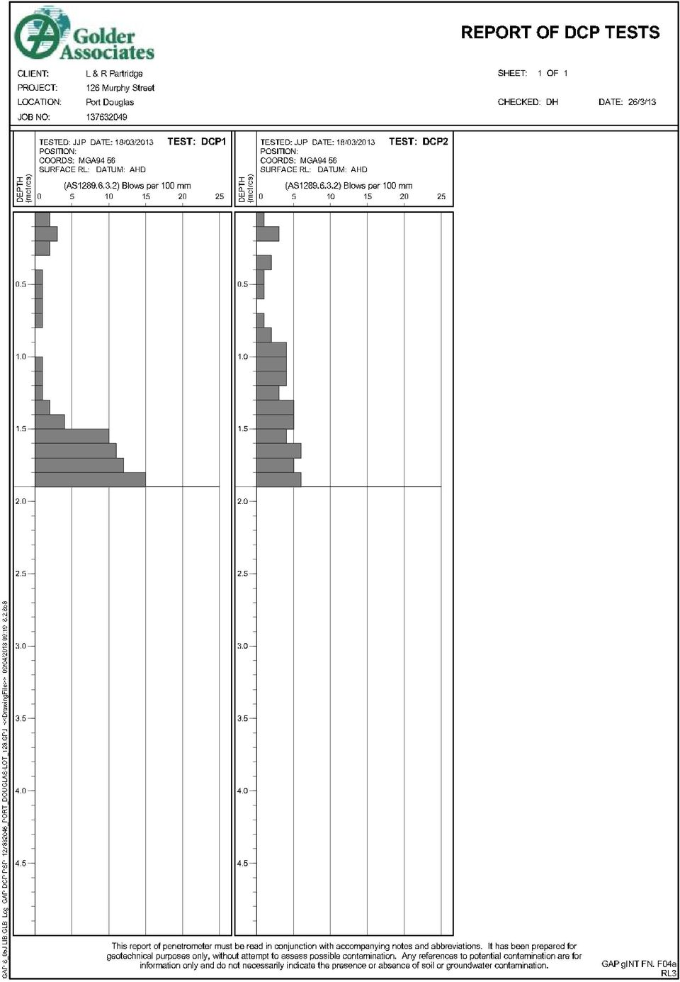
3 LOT 126, MURPHY STREET 1.0 INTRODUCTION At the request of Charles Wright Architects (CWA), Golder Associates (Golder) has undertaken a geotechnical investigation for a proposed residence at Lot 126 Murphy Street, Port Douglas. The investigation has been conducted in general accordance with our proposal (Golder Reference P P-Rev0) dated 13 March The aim of the investigation was to assess geotechnical and groundwater conditions at the site of the proposed development and to provide the following information: Subsurface conditions at the site; Stability of the slopes following proposed development and comments on slope stabilisation, if necessary; To assess the risk of upslope hazards, including the potential for rockfall and debris flows; Comments on foundation options and provide geotechnical design parameters; To provide a site classification as per AS2870. This report presents the results of the geotechnical investigation together with preliminary geotechnical input related to the items outlined above. As final details related to the proposed foundation types and structural loads are not known at this time, all geotechnical comments provided in this report should be considered preliminary in nature and should be reviewed and, if necessary, revised once the final design details are available. This report is based on drawings provided to Golder by CWA and geotechnical investigation and laboratory testing undertaken by Golder. 2.0 REGIONAL GEOLOGY The Queensland Department of Natural Resources and Mines 1: Geological Map Mossman, Sheet SE 55-1, indicates that the site is underlain by the late Silurian / Devonian Hodgkinson Formation dominated by arenite rich conglomerates. Subsurface conditions encountered in the test pits are considered to be consistent with the materials indicated on the geological map. 3.0 FIELDWORK 3.1 Methods The field investigation was carried out on 19 March 2013 under the full time supervision of a geotechnical engineer from Golder. The fieldwork consisted: Site walkover of the site; Excavation of two test pits (TP1 and TP2) to a maximum depth of 3.0 m. Observation and logging of two cuttings where the soil / rock profile is exposed; Performance of a Dynamic Cone Penetrometer (DCP) test adjacent to each of the test pits. The approximate test pit locations are indicated on Figure 1. Ground surface levels were interpolated from contour information presented on the RPS Contour and Detail Surveying drawing ( ) dated 26 November 2012 provided by CWA. April 2013 Report No R-Rev0 2

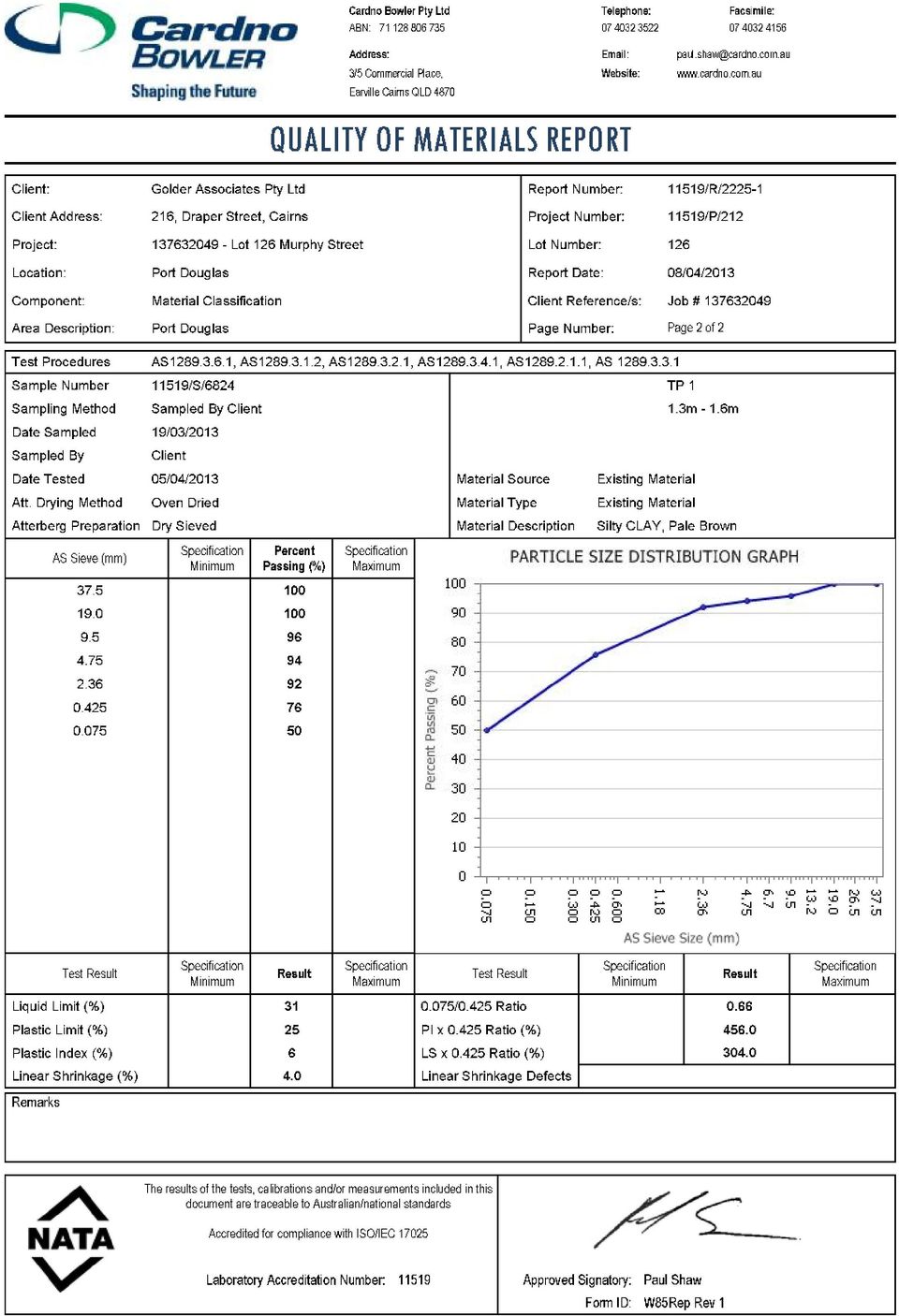
4 LOT 126, MURPHY STREET 3.2 Site Overview The site is sloping to the southwest at approximately 25 degrees. Its currently undeveloped and is predominately covered by dense rainforest vegetation. A level platform near the centre of the Lot is situated between an old rock retaining wall and a low cut batter where weathered bedrock is exposed. Disused concrete steps are located north of the platform, and an open concrete drain runs along the northeast lot boundary. A second low cutting exposing weathered bedrock is located at the south corner of the Lot near the end of the concrete driveway. Site drainage is toward the west corner. 3.3 Subsurface Conditions General sub soil conditions comprise localised uncontrolled fill overlying natural topsoil, colluvium and weathered bedrock. The fill deposits are associated with the level bench near the centre of the Lot, with minor deposits noted along the western property boundary. The colluvium thickens toward the southwest portion of the Lot. The thickness of colluvium and residual soils was noted to a depth of 2.9 m below ground level in Test Pit 1 before grading to low strength rock The approximate limits of the uncontrolled fill and the thickened colluvium are illustrated on Figures 1 and 2. Detailed descriptions of the subsurface conditions are presented in Appendix A. The conditions encountered were generally as follows: GL to 0.4/1.9m Topsoil: very loose to loose silty Sand. 1.9 to 2.9 m Colluvium / Residual soil: very dense silty clayey Sand. Deeper than 0.4/2.9 Extremely weathered to highly weathered rock (phyilite), extremely low to low and low to medium strength Groundwater was not encountered in the test pits to the depths advanced at the time of investigation. It should be noted that groundwater levels may fluctuate seasonally and during heavy rainfall periods. 4.0 LABORATORY TESTING Laboratory plasticity and particle distribution tests were carried out on samples of the soils encountered to confirm field classifications. Laboratory test result sheets are presented in Appendix B and are summarised in Table 1 below. Table 1: Summary of Laboratory Testing ID Depth (m) Material Emerson Class Number Grading (%) Plasticity (%) Gravel Sand Fines LL PI TP Silty CLAY TP Silty CLAY Due to the nature of the materials encountered on site, undisturbed samples for shrink/swell testing could not be recovered. April 2013 Report No R-Rev0 3

5 LOT 126, MURPHY STREET 5.0 ENGINEERING COMMENTS 5.1 Stability Stability analyses were carried out for the site profile indicated on Figure 2 for the existing slope profile. Based on judgement and previous experience with similar materials, the following strength parameters were adopted for the stability analyses: Table 2: Strength Parameters for Slope Stability Analyses Material Type Strength Parameters Fill c = 3 kpa = 28 Top Soil c = 2 kpa = 28 Colluvium c = 3 kpa = 28 Residual soils c = 5 kpa = 30 Inferred Weathered Rock c = 8 kpa = 34 Analyses were performed for what were considered to be dry or normal conditions and for what were considered to be wet or extreme conditions. A pore water pressure co-efficient, R u = 0.2 was used to simulate seepage/water infiltration for extreme conditions within the soils and R u = 0.1 within weathered rock zones respectively. The analyses were carried out for a potential failure surfaces using the proprietary computer software SLOPE/W. The results of the stability analyses are presented in Appendix C and are summarised as follows: Table 3: Results of Stability Analyses Slope Upslope Middle Platform Downslope Profile Calculated Factor of Safety (FOS) Dry Conditions Existing Proposed Existing Proposed Existing Proposed Wet Conditions For the purposes of assessing stability at this site we consider that a factor of safety 1.5 should be achieved for the dry conditions modelled and that a factor of safety 1.3 should be achieved for the wet, extreme conditions modelled. The results of the stability analyses indicate that the profile at the location of section A-A has adequate factors of safety for the upslope and downslope conditions modelled. The uncontrolled fill deposit in the middle platform at the location of section A-A is marginally stable under dry conditions and may be unstable under wet conditions for the condition modelled. Please refer to section 0 for discussion of uncontrolled fill. Subject to the adoption of standard engineering practices relevant to hillside construction, we consider that the proposed development has a low risk of large scale instability. The risk from upslope hazards including rock fall, slips and debris avalanche is considered to be low. April 2013 Report No R-Rev0 4

6 LOT 126, MURPHY STREET As is the case for all developments involving cut/fill earthworks in the Cairns area, some minor instability should be expected on batter faces. This instability is expected to be in the form of relatively minor slips and slumps on locally steep slopes or unsupported batters, and to occur during or after prolonged periods of heavy rainfall. Some ravelling may be anticipated in the rock batters. Given the low risk to residential development, this instability is generally accepted in the Cairns area and must be accepted by all parties involved in the proposed development. 5.2 Drainage It is recommended that the existing upslope cut-off drain is maintained (and improved if necessary) to help reduce the amount of surface and subsurface flow through and across the site. The discharge from this drain should be controlled and not allowed to flow across the site surface. All stormwater from rooftops or paved areas should be collected and directed away from the site via pipes or lined drains rather than be allowed to flow across the site and down the slope. 5.3 Site Preparation and Earthworks It is anticipated that the natural soils and fill at the site should be able to be excavated using normal capacity hydraulic earthmoving equipment, while excavation below the level where weathered rock was encountered may require hydraulic rock breaker equipment if excavation is required. Excavated materials are likely to comprise residual, (silty-sandy clay) soils and small amounts of fill material on the driveway. Some cobbles and boulders may also be encountered. Should filling be required, site preparation should include the following: Removal of vegetation, and stripping of topsoil and soil containing signification amounts of organic material from the footprint of the proposed fill. Earthworks should be conducted with particular attention to trees, if any, that may be considered environmentally significant. Local depressions left by the removal of root boles may need to be filled and these should be backfilled with engineered fill, compacted in layers. Excavate and remove un-engineered fill, where encountered. Compact subgrade areas with a heavy roller to reveal soft or loose zones. Soft or loose materials that cannot be improved by compaction should be removed and replaced with engineered fill, or excavated down to rock; Fill where required should be placed in layer not exceeding 200 mm loose thickness and compact to the recommended level prior to placing the next layer. The recommended compaction level is a density ratio of at least 95% using Standard Compaction. If required, additional imported fill materials should have a CBR value greater than 15% and a Plasticity Index of less than 10. Earthworks should be undertaken in accordance with AS Guidelines on Earthworks for Commercial and Residential Developments. It is recommended the Earthworks should be supervised by a suitably qualified person and all filling should be checked by field density testing. April 2013 Report No R-Rev0 5

7 LOT 126, MURPHY STREET 5.4 Footings and Site Classification No details of the footings or the structural loading for the proposed development have been provided to Golder at the present time. All geotechnical comments provided in this report should be considered preliminary in nature and should be reviewed and, if necessary, revised once the final design details are available. All footing excavations should be inspected by Golder to confirm the ground conditions are consistent with those on which these design guidelines are based Shallow Footings Pad and strip footings for the residence supporting vertical loads should be founded at least 0.5 m into low strength (or better) rock based on the parameters in Table 4. Footings for ancillary structures should where possible be founded in bedrock, but may be sized using the parameters presented in the table below. Despite no water table being observed in any test pit, a worst case scenario of the water table being located at the base of the footing has been assumed for this analysis. Design parameters are based on footing excavations being level, clean, dry and free of loose, softened and disturbed materials at the time of pouring concrete. Allowable bearing pressures and geotechnical design parameters for shallow footings are shown in Table 4. Table 4: Design Parameters for Shallow Footings Founding Strata Unit Weight ( ) Friction Angle ( ) Modulus (E) Allowable Bearing Pressure (Vertical) Dense to very dense silty Sand 18 kn/m to 20 MPa 120 kpa Medium dense to dense silty Sand 18 kn/m to 15 MPa 80 kpa Engineered fill 18 kn/m to 20 MPa 100 kpa Very low strength extremely weathered rock 22 kn/m MPa 600 kpa Deep Footings If structure loads cannot be economically supported on high level footings, bored cast in situ piles could be considered. Piled footings should penetrate through the residual soil / colluvium and should extend at least three times their diameter into the weathered rock. Design of piles should be in accordance with Australian Standard AS Piling Design and installation. Preliminary assessment of pile sizes and founding levels using static analyses could be based on the parameters presented in Table 5. For limit state strength design, a geotechnical strength reduction factor of 0.5 applied to the ultimate pressures is suggested. Selection of a design value for base capacity should consider materials four pile diameters below base level. Table 5: Parameters for Bored Cast In Situ Piles Material Allowable End Bearing (kpa) Allowable Shaft Adhesion (kpa) Dense to very dense silty Sand - - Medium dense to dense silty Sand - - Very low strength extremely weathered rock Note: Shaft adhesion and end bearing capacities in Table 5 apply when the pile length (L) is greater than 4 times the pile diameter (d). If L/d<4, use parameters for shallow footings. Design end bearing should consider material capacity within 4 pile diameters below founding level. April 2013 Report No R-Rev0 6
 rock based on the parameters in Table 4.")
8 LOT 126, MURPHY STREET Bored pile settlements will depend on footing shape, applied load and pile cleanliness on casting concrete, and should be assessed once these characteristics are known. As a preliminary guide, footing settlements under static serviceability loads would not be expected to exceed about 1.5% of pile diameter for properly constructed bored piles using allowable bearing pressures presented in Table 5. Parameters are based on foundation excavations being clean, dry and free of loose, softened and disturbed materials at the time of pouring concrete. It is recommended that bored pile drilling be logged by a geotechnical engineer to confirm ground conditions present and that geotechnical capacity meets the design loads Site Classification In accordance with AS Residential slabs and footings Construction, the site is classified as Class P due to uncontrolled fill and steep slopes. Footings should be designed in accordance with the parameters outlined above. Based on site reactivity, the soil profile behaviour would be equivalent to a site with an S site classification. 5.5 Uncontrolled Fill In the absence of an engineers certification, exiting fill is considered to be uncontrolled. The uncontrolled fill is localised with relatively minor volumes. The uncontrolled fill is not considered suitable to support structural loads, and the uncontrolled fill has been shown to be marginally stable. It is our understanding that the residential footings are planned to be extended into rock, therefore the uncontrolled fill is not deemed to be detrimental to stability of the residence. All landscape structures including driveways, garden walls, footpaths, etc. should likewise be founded in natural soil/rock beneath the uncontrolled fill, or on engineered fill. 5.6 Retaining Walls For permanent retaining structures, it is recommended that drainage be provided behind all retaining structures to help prevent the development of water pressures on the back of the walls. In addition, the drainage will need to be maintained throughout the life of the structure. If the designer is not satisfied that maintenance will be undertaken and the integrity of drainage maintained, then the retaining structure design should allow for the development of water pressures. Footings for retaining wall structures should be founded in rock or at least 0.5 m into the medium dense to dense or dense to very dense silty sands, the parameters presented in Table 4 should be used for design, along with the earth pressure coefficients presented in Table 6. Table 6: Geotechnical Design Parameters for Retaining Walls Material Engineered fill / Colluvium Very Low and Low Strength Weathered Rock Active Earth Pressure Coefficient (k a ) * Assumes horizontal backfill behind wall At Rest Earth Pressure Coefficient (k o ) Passive Earth Pressure Coefficient (k o ) Unit Weight (kn/m 3 ) 0.3* Bearing pressures presented in Table 4 reduced by one-third for inclined resultant forces from lateral pressures could be used to size retaining wall footings. All retaining wall excavations should be inspected by Golder to confirm the ground conditions are consistent with those on which these design guidelines are based. April 2013 Report No R-Rev0 7

9 LOT 126, MURPHY STREET 6.0 LIMITATIONS Your attention is drawn to the document Limitations, which is included in the appendices of this report. The statements presented in this document are intended to advise you of what your realistic expectations of this report should be. The document is not intended to reduce the level of responsibility accepted by Golder Associates, but rather to ensure that all parties who may rely on this report are aware of the responsibilities each assumes in so doing. We would be pleased to answer any questions about this important information from the reader of this report. GOLDER ASSOCIATES PTY LTD Gaozhao Lu Geotechnical Engineer Jules Darras Principal Engineering Geologist GZL/JJP/JD/dh A.B.N Golder, Golder Associates and the GA globe design are trademarks of Golder Associates Corporation. \\cns1-s-file02\jobs\geo\2013\ cwa - geo invest - lot 126 murphy street, port douglas\corr out\ r-rev0.docx April 2013 Report No R-Rev0 8

10 E E E E E E E E POINT RD. MURPHY ST. MACROSSAN ST. CONCRETE DRAIN O W EN ST E E E E A E E E E E E E E E E E E??? E E E E E?? E E E E E E E E E E E E E E E RP EE E E E E E E E CONCRETE DRIVEWAY 33.0 E E E EE 32.0 CO NC RET E DRIV EW AY 31.0 E E E E E E E E EE E ? ? ???? 32.0??? ?????? E E E E M UR PH Y STR EET SITE INVESTIGATION LOCATIONS Plot Date: 9 April 2013 Time:1:39:12 PM By: Farlow, Alan Path: K:\GEO\2013\ CWA - Geo Invest - Lot 126 Murphy Street, Port Douglas\FIGURES - File Name: R-F001-F002-Rev0.dwg Xref: GAP_LOGO-A3.dwg; XREF-Existing Site Features.dwg; XREF-EG Survey.dwg; A201_R3.jpg; BING IMAGE.JPG; LOCALITY PLAN - PORT DOUGLAS LEGEND NOT FOR CONSTRUCTION - ISSUED FOR m 1:200 CLIENT PROJECT LINDSAY AND ROBYN PARTRIDGE GEOTECHNICAL INVESTIGATION DRAWN BY DATE DRAWING TITLE CHECKED BY DATE SITE INVESTIGATION LOCATIONS AND LOCALITY PLAN - LOT 126 MURPHY STREET, PORT DOUGLAS DOC No DOC TYPE SCALE SHEET SIZE PROJECT No FIGURE No REVISION GOLDER ASSOCIATES PTY. LTD. 1:200 A R F001 0 FIGURE 1 C GOLDER ASSOCIATES PTY. LTD. INFORMATION CONTAINED ON THIS DRAWING IS THE COPYRIGHT OF GOLDER ASSOCIATES PTY. LTD. UNAUTHORISED USE OR REPRODUCTION OF THIS PLAN EITHER WHOLLY OR IN PART WITHOUT WRITTEN PERMISSION INFRINGES COPYRIGHT.

11 ? REALITIVE LEVEL (m) TP2 (1.0m Nth) CONCRETE DRAIN TP1 DCP1 (4.5m Sth) EASEMENT BOUNDARY? A Plot Date: 9 April 2013 Time:1:40:39 PM By: Farlow, Alan Path: K:\GEO\2013\ CWA - Geo Invest - Lot 126 Murphy Street, Port Douglas\FIGURES - File Name: R-F001-F002-Rev0.dwg Xref: GAP_LOGO-A3.dwg; XREF-Existing Site Features.dwg; XREF-EG Survey.dwg; A201_R3.jpg; BING IMAGE.JPG; NOT FOR CONSTRUCTION - ISSUED FOR m 1:200 CLIENT PROJECT LINDSAY AND ROBYN PARTRIDGE GEOTECHNICAL INVESTIGATION DRAWN BY DATE DRAWING TITLE CHECKED BY DATE SECTION A - LOT 126 MURPHY STREET, PORT DOUGLAS DOC No DOC TYPE SCALE SHEET SIZE PROJECT No FIGURE No REVISION GOLDER ASSOCIATES PTY. LTD. 1:200 A R F002 0 FIGURE 2 C GOLDER ASSOCIATES PTY. LTD. INFORMATION CONTAINED ON THIS DRAWING IS THE COPYRIGHT OF GOLDER ASSOCIATES PTY. LTD. UNAUTHORISED USE OR REPRODUCTION OF THIS PLAN EITHER WHOLLY OR IN PART WITHOUT WRITTEN PERMISSION INFRINGES COPYRIGHT.

12 LOT 126, MURPHY STREET APPENDIX A Results of Field Investigation April 2013 Report No R-Rev0 9

13

14

15
16 EXPLANATION OF NOTES, ABBREVIATIONS & TERMS USED ON BOREHOLE AND TEST PIT REPORTS DRILLING/EXCAVATION METHOD AS* Auger Screwing RD Rotary blade or drag bit NQ Diamond Core - 47 mm AD* Auger Drilling RT Rotary Tricone bit NMLC Diamond Core - 52 mm *V V-Bit RAB Rotary Air Blast HQ Diamond Core - 63 mm *T TC-Bit, e.g. ADT RC Reverse Circulation HMLC Diamond Core 63mm HA Hand Auger PT Push Tube BH Tractor Mounted Backhoe ADH Hollow Auger CT Cable Tool Rig EX Tracked Hydraulic Excavator DTC Diatube Coring JET Jetting EE Existing Excavation WB Washbore or Bailer NDD Non-destructive digging HAND Excavated by Hand Methods PENETRATION/EXCAVATION RESISTANCE L M H R Low resistance. Rapid penetration possible with little effort from the equipment used. Medium resistance. Excavation/possible at an acceptable rate with moderate effort from the equipment used. High resistance to penetration/excavation. Further penetration is possible at a slow rate and requires significant effort from the equipment. Refusal or Practical Refusal. No further progress possible without the risk of damage or unacceptable wear to the digging implement or machine. These assessments are subjective and are dependent on many factors including the equipment power, weight, condition of excavation or drilling tools, and the experience of the operator. WATER GROUNDWATER NOT OBSERVED GROUNDWATER NOT ENCOUNTERED SAMPLING AND TESTING SPT 4,7,11 N=18 30/80mm RW HW HB DS BDS G W FP FV PID PM PP U63 WPT DCP CPT CPTu Water level at date shown Water inflow Partial water loss Complete water loss The observation of groundwater, whether present or not, was not possible due to drilling water, surface seepage or cave in of the borehole/test pit. The borehole/test pit was dry soon after excavation. However, groundwater could be present in less permeable strata. Inflow may have been observed had the borehole/test pit been left open for a longer period. Standard Penetration Test to AS ,7,11 = Blows per 150mm. N = Blows per 300mm penetration following 150mm seating Where practical refusal occurs, the blows and penetration for that interval are reported Penetration occurred under the rod weight only Penetration occurred under the hammer and rod weight only Hammer double bouncing on anvil Disturbed sample Bulk disturbed sample Gas Sample Water Sample Field permeability test over section noted Field vane shear test expressed as uncorrected shear strength (s v = peak value, s r = residual value) Photoionisation Detector reading in ppm Pressuremeter test over section noted Pocket penetrometer test expressed as instrument reading in kpa Thin walled tube sample - number indicates nominal sample diameter in millimetres Water pressure tests Dynamic cone penetration test Static cone penetration test Static cone penetration test with pore pressure (u) measurement Ranking of Visually Observable Contamination and Odour (for specific soil contamination assessment projects) R = 0 R = 1 R = 2 R = 3 No visible evidence of contamination Slight evidence of visible contamination Visible contamination Significant visible contamination R = A R = B R = C R = D No non-natural odours identified Slight non-natural odours identified Moderate non-natural odours identified Strong non-natural odours identified ROCK CORE RECOVERY TCR = Total Core Recovery (%) SCR = Solid Core Recovery (%) RQD = Rock Quality Designation (%) Length of core recovered Length of core run 100 Length of cylindrical core Length of core run recovered 100 Axial lengths of core Length of core run 100 mm 100 GAP Form No. 6 RL7 August 2010

17 METHOD OF SOIL DESCRIPTION USED ON BOREHOLE AND TEST PIT REPORTS FILL CLAY (CL, CI or CH) GRAVEL (GP or GW) ORGANIC SOILS (OL or OH or Pt) SAND (SP or SW) COBBLES or BOULDERS SILT (ML or MH) Combinations of these basic symbols may be used to indicate mixed materials such as sandy clay. CLASSIFICATION AND INFERRED STRATIGRAPHY Soil and Rock is classified and described in Reports of Boreholes and Test Pits using the preferred method given in AS , (Amdt and Amdt2 1994), Appendix A. The material properties are assessed in the field by visual/tactile methods. Particle Size Major Division Sub Division Particle Size BOULDERS > 200 mm COBBLES 63 to 200 mm Coarse 20 to 63 mm GRAVEL Medium 6.0 to 20 mm Fine 2.0 to 6.0 mm Coarse 0.6 to 2.0 mm SAND Medium 0.2 to 0.6 mm Fine to 0.2 mm SILT to mm CLAY < mm CL/ML Clay/Silt CL Low plasticity clay OL or ML - Low liquid limit silt Plasticity Properties CI Medium plasticity clay OL or ML Low liquid limit silt CH High plasticity clay OH or MH High liquid limit silt Liquid Limit (%) MOISTURE CONDITION AS Symbol Term Description D Dry Sands and gravels are free flowing. Clays & Silts may be brittle or friable and powdery. M Moist Soils are darker than in the dry condition & may feel cool. Sands and gravels tend to cohere. W Wet Soils exude free water. Sands and gravels tend to cohere. CONSISTENCY AND DENSITY AS Symbol Term Undrained Shear Strength Symbol Term Density Index % SPT N # VS Very Soft 0 to 12 kpa VL Very Loose Less than 15 0 to 4 S Soft 12 to 25 kpa L Loose 15 to 35 4 to 10 F Firm 25 to 50 kpa MD Medium Dense 35 to to 30 St Stiff 50 to 100 kpa D Dense 65 to to 50 VSt Very Stiff 100 to 200 kpa VD Very Dense Above 85 Above 50 H Hard Above 200 kpa In the absence of test results, consistency and density may be assessed from correlations with the observed behaviour of the material. # SPT correlations are not stated in AS , and may be subject to corrections for overburden pressure and equipment type. GAP Form No. 5 RL8

18 LOT 126, MURPHY STREET APPENDIX B Laboratory Test Results April 2013 Report No R-Rev0 10

19

20
21
22 LOT 126, MURPHY STREET APPENDIX C Results of Stability Analysis April 2013 Report No R-Rev0 11
23
24
25
26
27
28
29
30
31
32
33
34
35 LOT 126, MURPHY STREET APPENDIX D Limitations April 2013 Report No R-Rev0 12
36 LIMITATIONS This Document has been provided by Golder Associates Pty Ltd ( Golder ) subject to the following limitations: This Document has been prepared for the particular purpose outlined in Golder s proposal and no responsibility is accepted for the use of this Document, in whole or in part, in other contexts or for any other purpose. The scope and the period of Golder s Services are as described in Golder s proposal, and are subject to restrictions and limitations. Golder did not perform a complete assessment of all possible conditions or circumstances that may exist at the site referenced in the Document. If a service is not expressly indicated, do not assume it has been provided. If a matter is not addressed, do not assume that any determination has been made by Golder in regards to it. Conditions may exist which were undetectable given the limited nature of the enquiry Golder was retained to undertake with respect to the site. Variations in conditions may occur between investigatory locations, and there may be special conditions pertaining to the site which have not been revealed by the investigation and which have not therefore been taken into account in the Document. Accordingly, additional studies and actions may be required. In addition, it is recognised that the passage of time affects the information and assessment provided in this Document. Golder s opinions are based upon information that existed at the time of the production of the Document. It is understood that the Services provided allowed Golder to form no more than an opinion of the actual conditions of the site at the time the site was visited and cannot be used to assess the effect of any subsequent changes in the quality of the site, or its surroundings, or any laws or regulations. Any assessments made in this Document are based on the conditions indicated from published sources and the investigation described. No warranty is included, either express or implied, that the actual conditions will conform exactly to the assessments contained in this Document. Where data supplied by the client or other external sources, including previous site investigation data, have been used, it has been assumed that the information is correct unless otherwise stated. No responsibility is accepted by Golder for incomplete or inaccurate data supplied by others. Golder may have retained subconsultants affiliated with Golder to provide Services for the benefit of Golder. To the maximum extent allowed by law, the Client acknowledges and agrees it will not have any direct legal recourse to, and waives any claim, demand, or cause of action against, Golder s affiliated companies, and their employees, officers and directors. This Document is provided for sole use by the Client and is confidential to it and its professional advisers. No responsibility whatsoever for the contents of this Document will be accepted to any person other than the Client. Any use which a third party makes of this Document, or any reliance on or decisions to be made based on it, is the responsibility of such third parties. Golder accepts no responsibility for damages, if any, suffered by any third party as a result of decisions made or actions based on this Document. GOLDER ASSOCIATES PTY LTD GAP Form No. LEG 04 RL 1
37 Golder Associates Pty Ltd 216 Draper Street Cairns, Queensland 4870 Australia T:
EARTHWORKS COMPLETION REPORT ELLEN STIRLING PARADE, ELLENBROOK. Ellenbrook, W.A. Georgiou Group Pty Ltd
 EARTHWORKS COMPLETION REPORT ELLEN STIRLING PARADE, ELLENBROOK Ellenbrook, W.A. Georgiou Group Pty Ltd GEOTPERT08050AZ-AH 27 March 2013 EARTHWORKS COMPLETION REPORT ELLEN STIRLING PARADE, ELLENBROOK Ellenbrook,
CIVL451. Soil Exploration and Characterization
 CIVL451 Soil Exploration and Characterization 1 Definition The process of determining the layers of natural soil deposits that will underlie a proposed structure and their physical properties is generally
Pavements should be well drained both during and upon completion of construction. Water should not be allowed to pond on or near pavement surfaces.
 Project No. 208-8719 January, 2009 Ref: 2-8719BR Anthony Hudson - Broadscale Geotechnical Investigation - Proposed Commercial Development - 52 Old Pacific Highway, Pimpama Page 32 iii) Pavements should
INSITU TESTS! Shear Vanes! Shear Vanes! Shear Vane Test! Sensitive Soils! Insitu testing is used for two reasons:!
 In-situ Testing! Insitu Testing! Insitu testing is used for two reasons:! To allow the determination of shear strength or penetration resistance or permeability of soils that would be difficult or impossible
Site Investigation. Some unsung heroes of Civil Engineering. buried right under your feet. 4. Need good knowledge of the soil conditions
 This is an attempt to create a stand alone self learning module on site investigation. Fasten your seat belts. Sit back, relax and enjoy. 1 2 Site Investigation Some unsung heroes of Civil Engineering
How To Design A Foundation
 The Islamic university - Gaza Faculty of Engineering Civil Engineering Department CHAPTER (2) SITE INVESTIGATION Instructor : Dr. Jehad Hamad Definition The process of determining the layers of natural
1 Mobilisation and demobilisation 1 Deep boring sum 2 Cone penetration tests sum 3 Miscellenous tests sum
 Malaysian Civil Engineering Standard Method of Measurement (MyCESMM) CLASS D: SITE INVESTIGATION WORK Measurement covered under other classes: Excavation not carried out for the purpose of soil investigation
Eurocode 7 - Geotechnical design - Part 2 Ground investigation and testing
 Brussels, 18-20 February 2008 Dissemination of information workshop 1 Eurocode 7 - Geotechnical design - Part 2 Ground investigation and testing Dr.-Ing. Bernd Schuppener, Federal Waterways Engineering
KWANG SING ENGINEERING PTE LTD
 KWANG SING ENGINEERING PTE LTD 1. INTRODUCTION This report represents the soil investigation works at Aljunied Road / Geylang East Central. The objective of the soil investigation is to obtain soil parameters
APPENDIX F GEOTECHNICAL REPORT
 The City of Winnipeg Bid Opportunity No. 101-2016 Template Version: C420150806 - RW APPENDIX F GEOTECHNICAL REPORT AECOM 99 Commerce Drive 204 477 5381 tel Winnipeg, MB, Canada R3P 0Y7 204 284 2040 fax
GUIDELINES FOR GEOTECHNICAL INVESTIGATION OF BRIDGE STRUCTURES. Materials Engineering Report No. 2009-8M (Supersedes Report No.
 GUIDELINES FOR GEOTECHNICAL INVESTIGATION OF BRIDGE STRUCTURES Materials Engineering Report No. 2009-8M (Supersedes Report No. 21) F CHOWDHURY GEOMECHANICS AND STRUCTURAL MATERIALS ENGINEER S REHMAN GEOTECHNICAL
c. Borehole Shear Test (BST): BST is performed according to the instructions published by Handy Geotechnical Instruments, Inc.
: BST is performed according to the instructions published by Handy Geotechnical Instruments, Inc.") Design Manual Chapter 6 - Geotechnical 6B - Subsurface Exploration Program 6B-2 Testing A. General Information Several testing methods can be used to measure soil engineering properties. The advantages,
Design Manual Chapter 6 - Geotechnical 6B - Subsurface Exploration Program 6B-2 Testing A. General Information Several testing methods can be used to measure soil engineering properties. The advantages,
How To Prepare A Geotechnical Study For A Trunk Sewer Project In Lincoln, Nebraska
 APPENDIX B Geotechnical Engineering Report GEOTECHNICAL ENGINEERING REPORT Preliminary Geotechnical Study Upper Southeast Salt Creek Sanitary Trunk Sewer Lincoln Wastewater System Lincoln, Nebraska PREPARED
Geotechnical Investigation Test Report
 Geotechnical Investigation Test Report Report No. htsc/rcd/ 3457 Dated: - 20/03/2010 Asphalt Standard Penetration Test as per IS 2131 ------------- IS 6403 Soil Job Card No - 1649 Cement Client/Department
SPECIFICATION FOR DYNAMIC CONSOLIDATION / DYNAMIC REPLACEMENT
 SPECIFICATION FOR DYNAMIC CONSOLIDATION / DYNAMIC REPLACEMENT 1.0 SOIL IMPROVEMENT 1.1 General Soil Investigation Information are provided in Part B1 annex as a guide to the Contractor for his consideration
FINAL REPORT ON SOIL INVESTIGATION
 FINAL REPORT ON SOIL INVESTIGATION FOR PROPOSED CONSTRUCTION AT SS-6B AREA AT HPCL VISAKH REFINERY VISAKHAPATNAM ANDHRA PRADESH J.J. ASSOCIATES(VISAKHAPATNAM) AETP(P) LIMITED #11-6-3, RockDale Layout,
INDIRECT METHODS SOUNDING OR PENETRATION TESTS. Dr. K. M. Kouzer, Associate Professor in Civil Engineering, GEC Kozhikode
 INDIRECT METHODS SOUNDING OR PENETRATION TESTS STANDARD PENETRATION TEST (SPT) Reference can be made to IS 2131 1981 for details on SPT. It is a field edtest to estimate e the penetration e resistance
Report. Geotechnical Investigation Proposed Easy Access Upgrade Marrickville Railway Station Station Street, Marrickville, NSW
 Pty Ltd ABN 62 084 294 762 Unit 5/39-41 Fourth Avenue, Blacktown, NSW 2148, Australia Tel : (02) 9679 8733 PO Box 1543, Macquarie Centre. North Ryde, NSW 2113 Fax : (02) 9679 8744 Report Geotechnical Investigation
FACTUAL GROUND INVESTIGATION
 FACTUAL GROUND INVESTIGATION REPORT COMMERCIAL/INDUSTRIAL REDEVELOPMENT OF LAND AT STEADMAN S WELTON CUMBRIA Web: www.geoenvironmentalengineering.com Telephone: 08456 768 895 Project Ref: 2013-657 Site
ENCE 4610 Foundation Analysis and Design
 This image cannot currently be displayed. ENCE 4610 Foundation Analysis and Design Shallow Foundations Total and Differential Settlement Schmertmann s Method This image cannot currently be displayed. Strength
product manual HS-4210 HS-4210_MAN_09.08 Digital Static Cone Penetrometer
 HS-4210_MAN_09.08 product manual HS-4210 Digital Static Cone Penetrometer Introduction This Manual covers the measurement of bearing capacity using the Humboldt Digital Static Cone Penetrometer (DSCP).
Geotechnical Investigation Reports and Foundation Recommendations - Scope for Improvement - Examples
 Geotechnical Investigation Reports and Foundation Recommendations - Scope for Improvement - Examples Prof. V.S.Raju (Formerly: Director, IIT Delhi & Professor and Dean, IIT Madras) Email: rajuvs_b@yahoo.com
Anirudhan I.V. Geotechnical Solutions, Chennai
 Anirudhan I.V. Geotechnical Solutions, Chennai Often inadequate In some cases, excess In some cases, disoriented Bad investigation Once in a while good ones Depends on one type of investigation, often
EVALUATING THE IMPROVEMENT FROM IMPACT ROLLING ON SAND
 EVALUATING THE IMPROVEMENT FROM IMPACT ROLLING ON SAND D.L. Avalle, Broons Hire (SA) Pty Ltd, Australia J.P. Carter, The University of Sydney, Australia Abstract Impact rolling, utilising a non-circular
Module 1 : Site Exploration and Geotechnical Investigation. Lecture 4 : In-situ tests [ Section 4.1: Penetrometer Tests ] Objectives
![Module 1 : Site Exploration and Geotechnical Investigation. Lecture 4 : In-situ tests [ Section 4.1: Penetrometer Tests ] Objectives](/thumbs/26/8734290.jpg "Module 1 : Site Exploration and Geotechnical Investigation. Lecture 4 : In-situ tests [ Section 4.1: Penetrometer Tests ] Objectives") Lecture 4 : In-situ tests [ Section 4.1: Penetrometer Tests ] Objectives In this section you will learn the following Penetrometer Tests Standard penetration test Static cone penetration test Dynamic cone
Lecture 4 : In-situ tests [ Section 4.1: Penetrometer Tests ] Objectives In this section you will learn the following Penetrometer Tests Standard penetration test Static cone penetration test Dynamic cone
Cone Penetration Testing in Geotechnical Practice. Tom Lunne Peter K. Robertson John J.M. Powell
 Cone Penetration Testing in Geotechnical Practice Tom Lunne Peter K. Robertson John J.M. Powell BLACKIE ACADEMIC & PROFESSIONAL An Imprint of Chapman & Hall London Weinheim New York Tokyo Melbourne Madras
1.0 INTRODUCTION 1 2.0 SCOPE OF WORK 2 3.0 EXECUTION OF FIELD WORK 2 4.0 LABORATORY TESTS 8 5.0 FINDINGS OF THE GEOTECHNICAL INVESTIGATION 9
 REPORT ON GEOTECHNICAL INVESTIGATION FOR LPG MOUNDED STORAGE AT VISAKHA REFINERY, MALKAPURAM, VISAKHAPATNAM (A.P) FOR HINDUSTAN PETROLEUM CORPORATION LIMITED CONTENTS SR.NO. DESCRIPTION PAGE NO. 1.0 INTRODUCTION
Soils, Foundations & Moisture Control
 Soils, Foundations & Moisture Control Soil The top loose layer mineral and/or organic material on the surface of the Earth that serves as a natural medium for the growth of plants and support for the foundations
INTERNATIONAL JOURNAL OF CIVIL AND STRUCTURAL ENGINEERING Volume 3, No 3, 2013
 INTERNATIONAL JOURNAL OF CIVIL AND STRUCTURAL ENGINEERING Volume 3, No 3, 2013 Copyright by the authors - Licensee IPA- Under Creative Commons license 3.0 Research article ISSN 0976 4399 Reliability of
COMPENDIUM OF INDIAN STANDARDS ON SOIL ENGINEERING PART 2
 (PREVIEW) SP 36 (Part 2) : 1988 COMPENDIUM OF INDIAN STANDARDS ON SOIL ENGINEERING PART 2 IS 1893 : 1979 (Reaffirmed 1987) CODE OF PRACTICE FOR SUBSURFACE INVESTIGATION FOR FOUNDATIONS 1.1 This code deals
Strength Determination of "Tooth-Paste" Like Sand and Gravel Washing Fines Using DMT
 Strength Determination of "Tooth-Paste" Like Sand and Gravel Washing Fines Using DMT David L. Knott, P.E. and James M. Sheahan, P.E. HDR Engineering, Inc. 3 Gateway Center Pittsburgh, PA 15222-1074 Phone:
Design, Testing and Automated Monitoring of ACIP Piles in Residual Soils
 Design, Testing and Automated Monitoring of ACIP Piles in Residual Soils Stephen W. Lacz 1, M. ASCE, P.E. and Richard C. Wells 2, F. ASCE, P.E. 1 Senior Professional, Trigon Kleinfelder, Inc., 313 Gallimore
GEOTECHNICAL INVESTIGATION. Adelaide Street Pollution Control Plant Outlet Structure Replacement London, Ontario
 September 2013 GEOTECHNICAL INVESTIGATION Adelaide Street Pollution Control Plant Outlet Structure Replacement London, Ontario Submitted to: Mr. Simon Jeater, C.Tech., Environmental Technician Stantec
USE OF CONE PENETRATION TEST IN PILE DESIGN
 PERIODICA POLYTECHNICA SER. CIV. ENG. VOL. 47, NO. 2, PP. 189 197 (23) USE OF CONE PENETRATION TEST IN PILE DESIGN András MAHLER Department of Geotechnics Budapest University of Technology and Economics
Geotechnical Measurements and Explorations Prof. Nihar Ranjan Patra Department of Civil Engineering Indian Institute of Technology, Kanpur
 Geotechnical Measurements and Explorations Prof. Nihar Ranjan Patra Department of Civil Engineering Indian Institute of Technology, Kanpur Lecture No. # 13 (Refer Slide Time: 00:18) So last class, it was
NOTES on the CONE PENETROMETER TEST
 GE 441 Advanced Engineering Geology & Geotechnics Spring 2004 Introduction NOTES on the CONE PENETROMETER TEST The standardized cone-penetrometer test (CPT) involves pushing a 1.41-inch diameter 55 o to
TECHNICAL REPORT ON SCALA DYNAMIC CONE PENETROMETER IRREGULARITY
 TECHNICAL REPORT ON SCALA DYNAMIC CONE PENETROMETER IRREGULARITY CETANZ Technical Report TR 1 Author(s) SJ Anderson, Geotechnics Ltd Report Date First Issue May 2010 Report Revision Date September 2011
Washington 98102-3699, mike.bailey@hartcrowser.com
 LESSONS LEARNED FROM A STONE COLUMN TEST PROGRAM IN GLACIAL DEPOSITS Barry S. Chen 1, P.E., Member, Geo-Institute and Michael J. Bailey 2, P.E., Member, Geo-Institute ABSTRACT A stone column test program
LABORATORY CLASSIFICATION OF SOILS FOR ENGINEERING PURPOSES
 Test Procedure for LABORATORY CLASSIFICATION OF SOILS FOR ENGINEERING PURPOSES TxDOT Designation: Tex-142-E Effective Date: August 1999 1. SCOPE 1.1 This method is a system for classifying disturbed and
GUIDELINE FOR HAND HELD SHEAR VANE TEST
 GUIDELINE FOR HAND HELD SHEAR VANE TEST NZ GEOTECHNICAL SOCIETY INC August 2001 CONTENTS Page 1.0 Introduction 2 2.0 Background 2 3.0 Recommended Practice 3 4.0 Undrained Shear Strength 3 5.0 Particular
SNC-Lavalin Inc. Montcalm Wastewater Pumping Station Upgrades - Geotechnical Report. October 2011
 SNC-Lavalin Inc. Montcalm Wastewater Pumping Station Upgrades - Geotechnical Report October 2011 SNC-Lavalin Inc Montcalm Wastewater Pumping Station Upgrades - Geotechnical Report Table of Contents 1.0
Soil behaviour type from the CPT: an update
 Soil behaviour type from the CPT: an update P.K. Robertson Gregg Drilling & Testing Inc., Signal Hill, California, USA ABSTRACT: An initial application of CPT results is to evaluate soil type and soil
GUIDELINES FOR SOIL FILTER MEDIA IN BIORETENTION SYSTEMS (Version 2.01) March 2008
 March 2008") GUIDELINES FOR SOIL FILTER MEDIA IN BIORETENTION SYSTEMS (Version 2.01) March 2008 The following guidelines for soil filter media in bioretention systems have been prepared on behalf of the Facility for
GUIDELINES FOR SOIL FILTER MEDIA IN BIORETENTION SYSTEMS (Version 2.01) March 2008 The following guidelines for soil filter media in bioretention systems have been prepared on behalf of the Facility for
NJ650.1404 Interception Drainage
 NJ650.1404 Interception Drainage Interception drainage is used to intercept surface and subsurface water. The investigation, planning, and construction of surface interception drains follow the requirements
Geotechnical Investigation using Standard Penetration Test (SPT) in Rangamati, Bandarban and Khagrachari Towns
 in Rangamati, Bandarban and Khagrachari Towns") 1. Introduction 1.1 Scope of Work The Asian Disaster Preparedness Centre (ADPC) is implementing the project Seismic Hazard and Vulnerability Mapping for Rangamati, Bandarban and Khagrachari Municipality.
1. Introduction 1.1 Scope of Work The Asian Disaster Preparedness Centre (ADPC) is implementing the project Seismic Hazard and Vulnerability Mapping for Rangamati, Bandarban and Khagrachari Municipality.
SERVICES 2015 ISO 18001
 SERVICES 2015 A family business with a solid foundation of experience, we handle all aspects of site investigation.... Phase 1 Environmental Studies Phase 2 Intrusive Investigations Phase 3 Remediation
Fundamentals of CONE PENETROMETER TEST (CPT) SOUNDINGS. J. David Rogers, Ph.D., P.E., R.G.
 SOUNDINGS. J. David Rogers, Ph.D., P.E., R.G.") Fundamentals of CONE PENETROMETER TEST (CPT) SOUNDINGS J. David Rogers, Ph.D., P.E., R.G. Cone Penetration Test CPT soundings can be very effective in site characterization, especially sites with discrete
Fundamentals of CONE PENETROMETER TEST (CPT) SOUNDINGS J. David Rogers, Ph.D., P.E., R.G. Cone Penetration Test CPT soundings can be very effective in site characterization, especially sites with discrete
REPORT. Earthquake Commission. Christchurch Earthquake Recovery Geotechnical Factual Report Merivale
 REPORT Earthquake Commission Christchurch Earthquake Recovery Geotechnical Factual Report Merivale REPORT Earthquake Commission Christchurch Earthquake Recovery Geotechnical Factual Report Merivale Report
patersongroup Geotechnical Investigation Proposed Residential Development 590 Hazeldean Road - Ottawa Prepared For 2118356 Ontario Inc.
 Geotechnical Engineering patersongroup Environmental Engineering Hydrogeology Geological Engineering Materials Testing Building Science Proposed Residential Development 590 Hazeldean Road - Ottawa Archaeological
HAULBOWLINE, CORK STATIC CONE PENETRATION TESTS FACTUAL REPORT
 HAULBOWLINE, CORK STATIC CONE PENETRATION TESTS FACTUAL REPORT CONE PENETRATION TESTS Cone resistance Local friction Porewater pressure Dissipations REPORT NO: RRM CONTRACT NO: GLOVER SITE INVESTIGATIONS
FREDERICK SHERRELL LTD
 FREDERICK SHERRELL LTD CONSULTING ENGINEERING GEOLOGISTS AND GEOTECHNICAL ENGINEERS 66 WEST STREET TAVISTOCK DEVON PL19 8AJ Your Ref: Our Ref: 2962.NS.JR Telephone: 01822 612915 Facsimile: 01822 617394
Use and Application of Piezocone Penetration Testing in Presumpscot Formation
 Use and Application of Piezocone Penetration Testing in Presumpscot Formation Craig W. Coolidge, P.E. Summit Geoengineering Services, Rockland, Maine ABSTRACT: This paper examines the advantages and limitations
JOHNSON STREET BRIDGE REPLACEMENT PROJECT
 JOHNSON STREET BRIDGE REPLACEMENT Victoria, BC GEOTECHNICAL INVESTIGATION REPORT Prepared for: City Hall No. 1 Centennial Square Victoria, BC VW 1P Prepared by: Stantec 7 Dominion Street, Suite 5 Burnaby,
Settlement of Foundations on Expansive Clays Due to Moisture Demand of Trees CIGMAT 2008
 Settlement of Foundations on Expansive Clays Due to Moisture Demand of Trees CIGMAT 2008 Kenneth E. Tand, P.E. Practicing Geotechnical Engineer FRIEND OR FOE Trees are our friends. They extract carbon
TECHNICAL NOTE: SI 01 SPECIFIC REQUIREMENTS FOR THE ACCREDITATION OF INSPECTION BODIES FOR SITE INVESTIGATION
 ACCREDITATION SCHEME FOR INSPECTION BODIES TECHNICAL NOTE: SI 01 SPECIFIC REQUIREMENTS FOR THE ACCREDITATION OF INSPECTION BODIES FOR SITE INVESTIGATION Technical Note SI 01: 3 February 2016 The SAC Accreditation
Chittagong Hill Tract Development Facilities (CHTDF) United Nations Development Programme
 United Nations Development Programme") Chittagong Hill Tract Development Facilities (CHTDF) United Nations Development Programme Main Report Deliverable 02 Sub-Surface Properties of Soil Development in Rangamati, Bandarban and Khagrachari Municipality
Chittagong Hill Tract Development Facilities (CHTDF) United Nations Development Programme Main Report Deliverable 02 Sub-Surface Properties of Soil Development in Rangamati, Bandarban and Khagrachari Municipality
Permeable Pavement Construction Guide
 Permeable Pavement Construction Guide Permeable pavement at Olympic Park, Waitakere Final Construction result What are permeable pavements? Permeable pavements are hard surface paving systems that reduce
A study on the Effect of Distorted Sampler Shoe on Standard Penetration Test Result in Cohesionless soil
 ISSN: 319-53 (An ISO 39: 00 Certified Organization) A study on the Effect of Distorted Sampler Shoe on Standard Penetration Test Result in Cohesionless soil Utpal Kumar Das Associate Professor, Department
Ingeniería y Georiesgos Ingeniería Geotécnica Car 19 a Nº 84-14 of 204 ; TEL : 6916043 E-mail: igr@ingeoriesgos.com
 The plot below presents the cross correlation coeficient between the raw qc and fs values (as measured on the field). X axes presents the lag distance (one lag is the distance between two sucessive CPT
PAPAMOA EAST URBAN DEVELOPMENT PART 1 AREA LIQUEFACTION HAZARD REVIEW Technical Report
 PAPAMOA EAST URBAN DEVELOPMENT PART 1 AREA LIQUEFACTION HAZARD REVIEW Technical Report Tauranga District Council Papamoa East Urban Development Strategy Part 1 Area Liquefaction Hazard Review Technical
CW 3110 SUB-GRADE, SUB-BASE AND BASE COURSE CONSTRUCTION TABLE OF CONTENTS
 December 2014 CW 3110 SUB-GRADE, SUB-BASE AND BASE COURSE CONSTRUCTION TABLE OF CONTENTS 1. DESCRIPTION... 1 1.1 General... 1 1.2 Definitions... 1 1.3 Referenced Standard Construction Specifications...
SECTION 31 20 00 EARTH MOVING
 SECTION 31 20 00 PART 1 - GENERAL 1.01 DESCRIPTION A. This Section describes the requirements for excavating, filling, and grading for earthwork at Parking Structure, new exit stair and as required to
STRUCTURES. 1.1. Excavation and backfill for structures should conform to the topic EXCAVATION AND BACKFILL.
 STRUCTURES 1. General. Critical structures may impact the integrity of a flood control project in several manners such as the excavation for construction of the structure, the type of foundation, backfill
Method Statement FOR. Soil Investigation
 Method Statement FOR Soil Investigation PREPARED BY JUNE 2010 Infratech ASTM CO., LTD. TABLE OF CONTENTS Chapter Title Page Table of Contents..1 List of Appendix... 2 List of Table... 2 List of Figures...
King Saud University College of Engineering Civil Engineering Department DEFORMATION OF PARTIALLY SATURATED SAND. Sultan Musaed Al-Ghamdi
 King Saud University College of Engineering Civil Engineering Department DEFORMATION OF PARTIALLY SATURATED SAND By Sultan Musaed Al-Ghamdi Submitted in Partial Fulfillment of The Required For the Degree
An Automatic Kunzelstab Penetration Test
 An Automatic Kunzelstab Penetration Test Yongyuth Sirisriphet 1, Kitidech Santichaianant 2 1 Graduated student: Faculty of Industrial Education in and Technology. King Mongkut's University of Technology
Caltrans Geotechnical Manual
 Cone Penetration Test The cone penetration test (CPT) is an in-situ sounding that pushes an electronic penetrometer into soil and records multiple measurements continuously with depth. Compared with rotary
System. Stability. Security. Integrity. 150 Helical Anchor
 Model 150 HELICAL ANCHOR System PN #MBHAT Stability. Security. Integrity. 150 Helical Anchor System About Foundation Supportworks is a network of the most experienced and knowledgeable foundation repair
Civil. 2. City of Seattle Supplement to the Specification for Road, Bridge and Municipal Construction, most current addition.
 Design Guide Basis of Design This section applies to the design and installation of earthwork and backfill. Design Criteria No stockpiling of excavation materials is allowed unless the Geotechnical Engineer
ANNEX D1 BASIC CONSIDERATIONS FOR REVIEWING STUDIES IN THE DETAILED RISK ASSESSMENT FOR SAFETY
 ANNEX D1 BASIC CONSIDERATIONS FOR REVIEWING STUDIES IN THE DETAILED RISK ASSESSMENT FOR SAFETY ANNEX D1: BASIC CONSIDERATIONS FOR REVIEWING STUDIES IN DRA FOR SAFETY D1-1 ANNEX D1 BASIC CONSIDERATIONS
Chapter 4 SUBSURFACE INVESTIGATION GUIDELINES
 Chapter 4 SUBSURFACE INVESTIGATION GUIDELINES Final SCDOT GEOTECHNICAL DESIGN MANUAL August 2008 Table of Contents Section Page 4.1 Introduction...4-1 4.2 Subsurface Investigation...4-2 4.2.1 Preliminary
CPTic_CSM8. A spreadsheet tool for identifying soil types and layering from CPTU data using the I c method. USER S MANUAL. J. A.
 CPTic_CSM8 A spreadsheet tool for identifying soil types and layering from CPTU data using the I c method. USER S MANUAL J. A. Knappett (2012) This user s manual and its associated spreadsheet ( CPTic_CSM8.xls
APPENDIX F. RESIDENTIAL WATER QUALITY PLAN: ALLOWABLE BMP OPTIONS
 APPENDIX F. RESIDENTIAL WATER QUALITY PLAN: ALLOWABLE BMP OPTIONS The following section provides descriptions, advantages, limitations, and schematics of allowable best management practices (BMPs) for
Appendix 9. Geotechnical Investigation
 Appendix 9 Geotechnical Investigation Soil Surveys Engineering Pty Limited Specialists in Applied Geotechnics A.B.N. 70 054 043 631 www.soilsurveys.com.au Directors PJ Dixon NT Perkins MV Geale GEJ Gray
The Manitoba Water Services Board SECTION 022180 Standard Construction Specifications PIPE EXCAVATION, BEDDING AND BACKFILL Page 1 of 11
 Page 1 of 11 Part 1 General 1.1 DESCRIPTION OF WORK.1 The work described herein shall consist of the excavation of trenches (or excavation of tunnels); the supply and placing of bedding and backfill materials;
Local Authority Building Control Technical Information Note 3 Driven and In-situ Piled Foundations
 Local Authority Building Control Technical Information Note 3 Driven and In-situ Piled Foundations Cambridge City Council - East Cambridgeshire District Council - Fenland District Council, Huntingdonshire
Preliminary Geotechnical Engineering Report North Park Pond Dam Edinborough Drive Charlotte, North Carolina S&ME Project No.
 Preliminary Geotechnical Engineering Report Edinborough Drive Charlotte, North Carolina S&ME Project No. 11-1-09 Prepared For: W.K. Dickson & Co., Inc. 70 Corporate Center Drive Raleigh, North Carolina
14.330 SOIL MECHANICS Assignment #4: Soil Permeability.
 Geotechnical Engineering Research Laboratory One University Avenue Lowell, Massachusetts 01854 Edward L. Hajduk, D.Eng, PE Lecturer PA105D Tel: (978) 94 2621 Fax: (978) 94 052 e mail: Edward_Hajduk@uml.edu
2009 Japan-Russia Energy and Environment Dialogue in Niigata S2-6 TANAKA ERINA
 Importance of the Site Investigation for Development of Methane Hydrate Hokkaido University Hiroyuki Tanaka Civil Engineer My Background Site Investigation Soil Parameters for Design Very Soft Clay and
GEOTECHNICAL ENGINEERING II. Subject Code : 06CV64 Internal Assessment Marks : 25 PART A UNIT 1
 GEOTECHNICAL ENGINEERING II Subject Code : 06CV64 Internal Assessment Marks : 25 PART A UNIT 1 1. SUBSURFACE EXPLORATION 1.1 Importance, Exploration Program 1.2 Methods of exploration, Boring, Sounding
Using Combination of SPT, DMT and CPT to Estimate Geotechnical Model for a Special Project in Turkey
 Using Combination of SPT, DMT and CPT to Estimate Geotechnical Model for a Special Project in Turkey Figen Orhun Onal GE, M.Sc., Site Works Manager, Zemin Etud ve Tasarım A.Ş., Istanbul, figen.orhun@zetas.com.tr
VOLUME III GEOLOGY, HYDROGEOLOGY & GEOTECHNICAL REPORT CAPITAL REGION RESOURCE RECOVERY CENTRE
 2.0 SITE INVESTIGATION METHODOLOGY The following section summarizes the Site investigation methodology applied during the subsurface investigation and hydrogeological assessment completed at the CRRRC
Appendix D.1. Testing Requirements for Infiltration, Bioretention and Sand Filter Subsoils
 Appendix D.1 Testing Requirements for Infiltration, Bioretention and Sand Filter Subsoils General Notes Pertinent to All Testing 1. For infiltration trench (I-1) and basin (I-2) practices, a minimum field
Geotechnical Testing Methods II
 Geotechnical Testing Methods II Ajanta Sachan Assistant Professor Civil Engineering IIT Gandhinagar FIELD TESTING 2 1 Field Test (In-situ Test) When it is difficult to obtain undisturbed samples. In case
Ohio Department of Transportation Division of Production Management Office of Geotechnical Engineering. Geotechnical Bulletin PLAN SUBGRADES
 Ohio Department of Transportation Division of Production Management Office of Geotechnical Engineering Geotechnical Bulletin GB 1 PLAN SUBGRADES Geotechnical Bulletin GB1 was jointly developed by the Offices
SECTION 3.3 - PAVEMENT DESIGN
 SECTION 3.3-3.3.1 GENERAL 3.3.2 SUBSURFACE DRAINAGE 3.3.3 DETERMINATION OF DESIGN TRAFFIC 3.3.4 SUBGRADE EVALUATION 3.3.5 PAVEMENT THICKNESS 3.3.5.1 GRANULAR PAVEMENTS WITH THIN BITUMINOUS SURFACING 3.3.5.2
Testing Procedures. Note: Please refer to Table 2 for a list of completed borings.
 Testing Procedures Drilling and Sampling: Standard penetration tests (SPT) were conducted for every ten feet of boring advancement. SPT tests were conducted in accordance with ASTM D1586, using a 140 pound
ENGINEERED FOUNDATIONS. Department of Public Works Jeff Hill, PE
 ENGINEERED FOUNDATIONS Department of Public Works Jeff Hill, PE What is an engineered foundation. A Foundation Design Developed by a Trained Professional (Engineer) Types of Foundations (All of which can
Assessment. Ian Uglow Technical Director, SLR Consulting iuglow@slrconsulting.com. 7 th October 2010
 Peat Stability Risk and Hazard Assessment Ian Uglow Technical Director, SLR Consulting iuglow@slrconsulting.com 7 th October 2010 What goes into a Peat Stability Risk Assessment? You will need: An understanding
BUILDING OVER OR NEAR WATER & SEWER MAINS POLICY
 MURRAY SHIRE COUNCIL BUILDING OVER OR NEAR WATER & SEWER MAINS POLICY ADOPTED: 1 May 2012 1 BUILDING OVER OR NEAR WATER AND SEWER MAINS POLICY CONTENTS 1. Objective... 2 2. Requirements for Building Near
Report on Engineering Geological Investigation: Test pit logs in KwaMhlanga for RDP houses development.
 Report on Engineering Geological Investigation: Test pit logs in KwaMhlanga for RDP houses development. 2012 Department of Geology GTX 713 Date Excavated: 18 April 2012 Machine: Bell 315SG Operator: Lesley
THE OBJECTIVES OF ROUTINE ROAD CUTS AND FILLS
 Chapter 11 Slope Stabiliza bilization and Stability of Cuts and Fills THE OBJECTIVES OF ROUTINE ROAD CUTS AND FILLS are 1) to create space for the road template and driving surface; 2) to balance material
EXCAVATION AND PILING NEAR SEWERS, STORMWATER DRAINS AND WATER MAINS
 NMP 1.4 EXCAVATION AND PILING NEAR SEWERS, STORMWATER DRAINS AND WATER MAINS Index Purpose... 2 Application... 2 Referral Agency... 2 Associated Requirements... 2 Referenced Standards...2 Definitions...
CHAPTER 1 INTRODUCTION
 CHAPTER 1 INTRODUCTION 1.1 Introduction The design and construction of foundations require a good knowledge of the mechanical behaviour of soils and of their spatial variability. Such information can be
A perforated conduit such as pipe, tubing or tile installed beneath the ground to intercept and convey ground water. or structures.
 BMP: SUBSURFACE DRAIN Definition A perforated conduit such as pipe, tubing or tile installed beneath the ground to intercept and convey ground water. PurRoses 1. To prevent sloping soils from becoming
Lighthouse Engineering, L.L.C.
 Registered Engineering Firm (F: 9334) Phone: 214-577-1077 Fax: 214-224-0549 Website: www.lighthouseeng.com Email: Office@LighthouseEng.com Thursday, September 04, 2014 TO: Our Client RE: Initial Engineering
Engineered, Time-Tested Foundation Repairs for Settlement in Residential and Light Commercial Structures. The Leading Edge.
 TM TM Engineered, Time-Tested Foundation Repairs for Settlement in Residential and Light Commercial Structures. SM The Leading Edge. 10 One Major Causes of foundation settlement or more conditions may
Designed and Engineered to Perform
 History EARTH CONTACT PRODUCTS, L.L.C., is a family owned company, based in Olathe, Kansas. This company was built upon Don May s U.S. Patented fourth-generation Steel Piering System that has led to the
Standard Test Method for Mechanical Cone Penetration Tests of Soil 1
 Designation: D 3441 98 AMERICAN SOCIETY FOR TESTING AND MATERIALS 100 Barr Harbor Dr., West Conshohocken, PA 19428 Reprinted from the Annual Book of ASTM Standards. Copyright ASTM Standard Test Method
GEOTECHNICAL ENGINEERING FORMULAS. A handy reference for use in geotechnical analysis and design
 GEOTECHNICAL ENGINEERING FORMULAS A handy reference for use in geotechnical analysis and design TABLE OF CONTENTS Page 1. SOIL CLASSIFICATION...3 1.1 USCS: Unified Soil Classification System...3 1.1.1