SNC-Lavalin Inc. Montcalm Wastewater Pumping Station Upgrades - Geotechnical Report. October 2011
|
|
|
- Buck Copeland
- 8 years ago
- Views:
Transcription
1 SNC-Lavalin Inc. Montcalm Wastewater Pumping Station Upgrades - Geotechnical Report October 2011

2

3 SNC-Lavalin Inc Montcalm Wastewater Pumping Station Upgrades - Geotechnical Report Table of Contents 1.0 Introduction Background Site Investigation Laboratory Testing Site and Subsurface Conditions Site Conditions Sub-Surface Conditions Soil Stratigraphy Groundwater Conditions Riverbank Stability Excavations and Shoring Foundations Waterways Permit Closure... 6 List of Figures Figure 01 Figure 02 Figure 03 Site Plan and Test Hole Layout Slope Stability Analysis Output Soft to Firm Cohesive Soils Apparent Earth Pressure Distributions List of Appendices Appendix A Appendix B Test Hole Logs Laboratory Testing October 2011 Our File No.: Page i

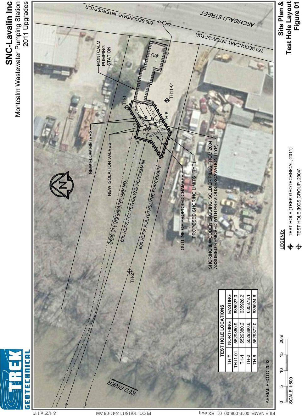
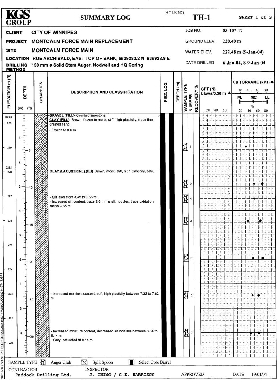
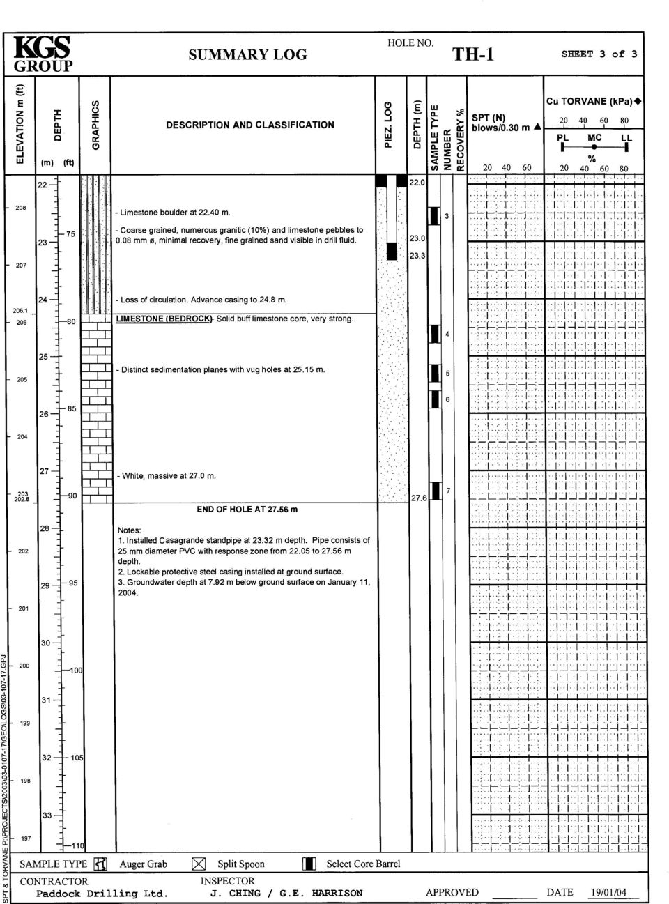
4 SNC-Lavalin Inc Montcalm Wastewater Pumping Station Upgrades - Geotechnical Report 1.0 Introduction This report summarizes the results of the geotechnical investigation completed by TREK Geotechnical Inc. (TREK) for the proposed upgrades to the Montcalm Wastewater Pumping Station in Winnipeg, Manitoba. The terms of reference for the investigation are included in an to SNC-Lavalin dated July 19, 2011 and included a sub-surface investigation, laboratory testing, riverbank slope stability analysis and the provision of recommendations for the design and construction of underground structures and shoring. 2.0 Background The Montcalm Pumping Station conveys wastewater from the Mission Sewer District across the Red River to the North End Water Pollution Control Centre along two forcemains. The pump station was constructed in the 1930 s and has received minor upgrades over the years. Major upgrades to the facility are now necessary. The proposed upgrades will require a 10.9 m deep excavation adjacent to the southwest corner of the pumping station in order to construct an access chamber and install two flow meters and two isolation valves on the existing forcemains. This excavation will require temporary shoring. The two forcemains were installed in the winter of 2004 using directional drilling methods. They were connected to the pump house within an excavation which was shored using soldier piles driven to a depth of about 12.2 m from grade (about 3 m below the base of the excavation) and timber lagging. It is our understanding that the soldier piles were removed but the timber lagging was likely left in place. KGS Group completed a geotechnical investigation in January of 2004 as part of the forcemain upgrades. Three test holes were drilled as part of this investigation in the vicinity of the pump station (TH-01, TH- 02, and TH-06) as shown on Figure 01. Test hole logs and survey information from this investigation were provided to TREK by the City of Winnipeg to aid in our analysis. The KGS test hole logs are included in Appendix A as complementary information to this report. The test hole completed by TREK (TH 11-01) supplements the previous subsurface and groundwater information. A cross section adjacent to the pumping station from the 2004 survey was used for the stability analysis. 3.0 Site Investigation One test hole (TH11-01) was drilled on September 22 nd 2011 by Maple Leaf Drilling Ltd. at the location shown on Figure 01. The test hole was drilled to power auger refusal with a mobile B40 drill rig using 125 mm solid stem augers. The test hole was completed under the supervision of TREK personnel and was visually classified using the Unified Soil Classification System (USCS). Disturbed (grab) and relatively undisturbed (Shelby tube) samples were recovered for laboratory testing. Standard penetration testing (SPT) was carried out to measure the consistency of the till and obtain disturbed samples of this soil unit. Soil samples were transported to TREK s soils laboratory in Winnipeg, Manitoba for further classification and testing. A standpipe piezometer was installed in the glacial till to measure short term groundwater levels. October 2011 Page 1 Our File No.:

5 SNC-Lavalin Inc Montcalm Wastewater Pumping Station Upgrades - Geotechnical Report A test hole log has been prepared for the drilling completed by TREK and is included in Appendix A. The test hole log includes a description and relative elevation of the soil units encountered, sample type and depth, the results of field and laboratory testing, and other pertinent information such as sloughing and groundwater seepage. 3.1 Laboratory Testing Laboratory testing was carried out to determine moisture content, plasticity (Atterberg limits) and undrained shear strength from pocket penetrometer, Torvane and unconfined compression tests. The results of the laboratory testing are included on the test hole log in Appendix A and reported separately in Appendix B. 4.0 Site and Subsurface Conditions 4.1 Site Conditions The site is located along the outside bend of the Red River at 23 Archibald Street, just upstream of CPR Keewatin Bridge. The majority of site is grass covered with some trees and shrubs near the top of bank and along the property boundaries. The riverbank slopes at about 10H:1V from the upland at the pumping station transitioning to about 4H:1V in the vicinity of the lower bank near the river's edge. Erosion of the lower portion of the riverbank is evident which is typical of riverbanks located on outside bends along the Red River. 4.2 Sub-Surface Conditions Soil Stratigraphy In descending order from ground surface, the sub-surface stratigraphy is as follows: Fill (Sand and Gravel, Clay) Silt Lacustrine Clay Glacial Till Limestone Bedrock A brief description of the soil units are provided as follows: Fill Sand and Gravel Sand and gravel (fill) was encountered in TH from surface to a depth of 0.5 m. The sand and gravel (fill) is light brown, dry to moist, compact and well graded. The moisture content from one sample had a moisture content of 5.1 %. A sand and gravel fill layer was encountered in one of the test holes drilled October 2011 Page 2 Our File No.:
 and undrained shear strength from pocket penetrometer, Torvane and unconfined")
6 SNC-Lavalin Inc Montcalm Wastewater Pumping Station Upgrades - Geotechnical Report during the 2004 investigation. Clay A 2.0 m thick layer of clay fill underlies the sand and gravel fill. The clay fill is silty, contains trace oxidation, is brown, moist, firm and based on visual classification is highly plastic. Moisture contents range from 37 to 51 % with an average of 44 %. Undrained shear strengths range from 12.5 to 84.3 kpa with an average of 48 kpa based on pocket penetrometer and Torvane tests. Clay (fill) was also encountered in two of the test holes drilled during the 2004 investigation. Silt A 0.3 m thick silt layer underlies the clay (fill). The silt contains some clay, is grey, moist and soft. Based on visual classification the silt is of low to intermediate plasticity. The moisture content of one sample was 35 %. Lacustrine Clay Lacustrine clay underlies the sand and gravel fill. The clay is brown near the surface, becoming grey at a depth of about 9 m. The brown and grey clay horizons are described separately as follows: Brown Clay The brown clay is silty and contains trace amounts of silt inclusions (<10 mm in diameter). Based on visual classification, the clay is highly plastic (CH). Moisture contents range from 44 to 54 % with an average of 51 %. Shear strengths range from 18.7 to 54.1 kpa with and average of 38.2 kpa indicating a soft to stiff consistency. Bulk unit weights from two samples were 16.5 and 16.9 kn/m 3. Grey Clay The underlying grey clay is silty and highly plastic based on a plastic limit of 18% and liquid limit of 77%. Moisture contents range from 46 to 62% with an average of 51% with a consistency generally from soft to firm. Measured shear strengths from all test types range from 9.6 to 68.3 kpa with and average of 30.8 kpa. Bulk unit weights range from 16.1 to 17.8 kn/m 3 with an average of 16.7 kn/m 3. Glacial Till Glacial silt till underlies the lacustrine clay at a depth of 16.9 m (elevation m). A glacial till transition zone was encountered from elevation to m. For comparison, the glacial silt till contact in the 2004 KGS investigation was reached at elevations ranging from to m. TH11-01 terminated at power auger refusal in the glacial till at a depth of 17.8 m (elevation m). Based on test holes advanced (cored) through the glacial till in 2004, the thickness of this unit is ranges from 6.0 to 7.5 m. The silt (till) contains trace clay, trace sand, trace gravel, trace cobbles, trace boulders, is light brown, dry to moist and poorly graded. Moisture contents range from 31% near the overlying clay contact to around 9% in the glacial till. The consistency of the till is very dense based on a Standard Penetration blow count (N) of 61 over 229 mm at a depth of 16.7 m. October 2011 Page 3 Our File No.:
 was also encountered in two of the test holes drilled during the 2004 investigation. Silt A 0.3 m thick silt layer underlies the clay (fill).")
7 SNC-Lavalin Inc Montcalm Wastewater Pumping Station Upgrades - Geotechnical Report Bedrock Limestone bedrock underlies the glacial till as evidenced by test holes from the 2004 investigation Groundwater Conditions Seepage was observed at 16.5 m below surface at the till interface in TH Within an hour after drilling, the water level in the test hole had risen to 12.1 m below surface. A standpipe piezometer was installed in the till to measure short-term groundwater levels. The piezometer was monitored on two occasions with a stabilized groundwater level reached at an approximate elevation of m. It is important to note however, that groundwater conditions may change seasonally, annually or as a result of construction activities. 5.0 Riverbank Stability There is no visual evidence of riverbank instabilities at this location at the time of the investigation. It is our understanding that no major grading works are required for the proposed construction although minor grading may be considered as part of the site restoration. Although the proposed upgrading works are not expected to negatively impact the existing riverbank stability, analysis was completed to assess the riverbank stability at the shoring location. A minimum factor of safety (FS) of 1.5 against slope instabilities is considered appropriate for potential slip surfaces at the proposed shoring and access chamber. The worst case groundwater and river levels were selected as a first step and compared against the factor of safety criteria. If a minimum factor of safety was not achieved under these conditions a more rigorous analysis would be undertaken. The stability analysis was conducted using a limit-equilibrium slope stability model (Slope/W) from the GeoStudio 2007 software package (Geo-Slope International Inc.). The cross section geometry used in the model is based on survey information from 2004 and the stratigraphic profile is based on the results of previous and current site investigations. A groundwater level of 2.0 m below surface for the clay and glacial till along with the winter (drawdown) river level (WWL) were used in the analysis as the worst case conditions. The soil properties used in the slope stability model are presented in Table 1. Unit weights are based on laboratory testing results. The lacustrine clay shear strengths are based on local experience and reflect large strain traixial testing results. The glacial till strengths are based on local experience and the limestone bedrock is considered impenetrable. Table 1 - Soil Properties Used in Slope Stability Analysis Soil Description Unit Weight (kn/m 3 ) Cohesion (kpa) Friction Angle (deg) Lacustrine Clay (Large strain strength envelope) Glacial Silt Till Limestone Bedrock Impenetrable October 2011 Page 4 Our File No.:

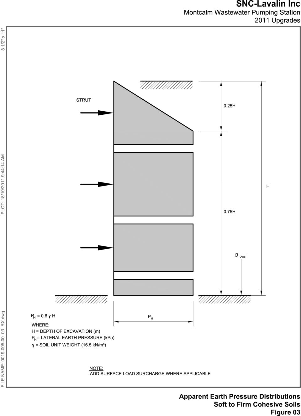
8 SNC-Lavalin Inc Montcalm Wastewater Pumping Station Upgrades - Geotechnical Report The calculated factor of safety for a potential slip surface at the west side of the proposed shoring limits for the assumed groundwater and river conditions is 1.61 as shown on Figure 02. This factor of safety exceeds the minimum target of 1.5 and additional analysis is not considered necessary. A critical factor of safety of 1.30 was calculated for a potential slip surface entering the slope approximately 49 m west of the proposed shoring location. 6.0 Excavations and Shoring It is our understanding that an excavation depth of 10.9 m (to elevation m) is required to complete the proposed upgrading works (City of Winnipeg Drawing L-S0001 Rev PB and L-B0003 Rev PB). Based on this excavation depth, conventional shoring will need to be braced or tied back. The earth pressure distributions provided in Figure 03 can be used for shoring design using a bulk unit weight of 16.5 kn/m 3 and an active earth pressure coefficient of 0.6. An undrained shear strength of 40 kpa for the brown clay and 30 kpa for the grey clay can be used for the design of shoring and the determination of an adequate factor of safety against toe instabilities. The undrained shear strengths were selected based on the measured undrained shear strength profile from all test types. Ground movements behind the shoring and associated settlement are largely unavoidable. The amount of movement cannot be predicted with a high degree of accuracy as it is as much a function of the excavation procedures and workmanship as it is of theoretical considerations. In this regard, good contact between the timber lagging and retained soil should be maintained throughout the construction process. Free draining sand fill should be used to fill in any voids behind the lagging. Additional recommendations can be provided should infrastructure sensitive to settlement exist in close proximity to the excavation. The lacustrine clay is underlain by a layer of glacial till under confined groundwater pressures. As a result, the potential for base heave and/or groundwater seepage into excavations must be considered. If base heave occurs causing hydraulic fracturing of the clay, there exists a potential for groundwater seepage into the excavation. This event could be sudden and catastrophic in nature. In this regard, sufficient resisting forces are required to counteract groundwater pressures. The resisting forces are a function of the thickness and unit weight of the clay above the till and to a lesser degree, shoring dimensions. An adequate factor of safety against base heave is achieved when the groundwater level in the till is at or below elevation m for the proposed excavation depth and geometry. In comparison, a groundwater elevation of m was measured at the clay till interface in October Based on a review of groundwater levels recorded in the winter of 2004, it is anticipated that the groundwater levels in the till may drop to approximately elevation m in response to drawdown of the river. It must be recognized however, that groundwater levels are likely to increase substantially during spring freshet before returning to normal summer levels. The recommended safe groundwater elevation is a function of excavation depth and shoring dimensions and should be re-calculated for any base elevation other than m or changes in shoring dimensions. A relief well is recommended to depressurize the till layer and achieve an adequate factor of safety against base heave. The well should be able to maintain the recommended safe groundwater elevation for the length of time the excavation is open and be able to accommodate fluctuations in groundwater October 2011 Page 5 Our File No.:

9 SNC-Lavalin Inc Montcalm Wastewater Pumping Station Upgrades - Geotechnical Report elevations. Groundwater quality should be evaluated to determine if it is acceptable to discharge directly into the river. It is important to note that the potential for seepage into the excavation exists when the groundwater elevation is above the base of the excavation. Should this occur, it will be necessary to dewater the excavation and/or lower the groundwater to an elevation lower than the base. Wood lagging from 2004 (if present) may create excavation difficulties and inhibit the installation of shoring. It is also understood that the excavation from the work carried out in 2004 was backfilled with gravel. In this regard, softening of the clay along the old excavation walls and base may be a consequence of water ponding in the gravel. Based on shop drawings from the 2004 construction, the H- Piles (soldier piles) were to be driven 3 m below the base of the excavation terminating within the clay a few meters above the till. Although it is our understanding that these piles were removed after construction, there may be remaining void spaces that could create preferential pathways for groundwater flow into the excavation. 7.0 Foundations Structures of this nature are often supported by a mat foundation buried deep into the soil where part (or all) of the loads may be compensated by the weight of removed soil. A maximum allowable bearing capacity of 115 kpa is recommended for the design of foundations on the clay at the proposed elevation of m. It should be noted that this bearing capacity is based on a maximum estimated settlement of 25mm at the maximum allowable bearing pressure. Should such settlement not be acceptable, a deep foundation system consisting of driven end bearing piles could be considered. Aside from consolidation settlement, vertical displacements of the structure can ensue if changes in the moisture content of the clay occur during construction, in this case drying. Measures to minimize the drying potential, for example a mud slab, may be considered. The uplift forces acting against the access chamber should also be considered in design and a groundwater level at existing ground surface should be used. 8.0 Waterways Permit A Waterways Permit from the City of Winnipeg is required to carry out the work. Based on the stability analysis and our review of the proposed works, we recommend that a Waterways permit be granted. It is expected that conditions of the permit are likely to include the stockpiling of materials well away from the top of bank and permission from any adjacent property owners where access may be required. The submission of a Waterway application should therefore include any proposed access and egress routes and stockpile locations. 9.0 Closure The geotechnical information provided in this report is in accordance with current engineering principles and practices (Standard of Practice). The findings and recommendations of this report were based on information provided (field investigations, laboratory testing, geometries, equipment specifications) and interpolation of soil and groundwater information between test holes. Soil conditions are natural deposits that can be highly variable across a site. If sub-surface conditions are different than the conditions October 2011 Page 6 Our File No.:

10 SNC-Lavalin Inc Montcalm Wastewater Pumping Station Upgrades - Geotechnical Report previously encountered on-site or those presented here, or if the assumptions presented in this report are not keeping with the overall design or construction procedures, we should be notified to review our recommendations and adjust our findings if necessary. All information provided in this report is subject to our standard terms and conditions for engineering services, a copy of which is provided to each of our clients with the original scope of work or standard engineering services agreement. If these conditions are not attached, and you are not already in possession of such terms and conditions, contact our office and you will be promptly provided with a copy. October 2011 Page 7 Our File No.:

11 SNC-Lavalin Inc Montcalm Wastewater Pumping Station Upgrades - Geotechnical Report Figures October 2011 Our File No.:

12 TH-2 TH-6 TH-1 TH11-01
13 SNC Lavalin - Montcalm Pump Station Upgrades 23 Archibald Street Working Cross Section 1 Existing Geometry Winter River Level (WRL) Elev. 222 m Groundwater Elevation 2 m below ground Name: Clay Unit Weight: 16.5 kn/m³ Cohesion: 5 kpa Phi: 14 Name: Silt Till Unit Weight: 20 kn/m³ Cohesion: 10 kpa Phi: 30 Name: Bedrock Shoring Extents Elevation, m File Name: XS1.gsz Distance, m Clay FS=1.61 Montcalm Pumping Station Silt Till Bedrock Figure 02

14
15 SNC-Lavalin Inc Montcalm Wastewater Pumping Station Upgrades - Geotechnical Report Appendix A Borehole Logs October 2011 Our File No.:

16 Sub-Surface Log Test Hole TH of 2 Client: SNC Lavalin Inc. Project Name: Montcalm Pumping Station Upgrades Contractor: Maple Leaf Drilling Method: 125mm Solid Stem Auger, B40 Mobile Truck Mount Project Number: Location: UTM 14 N E Ground Elevation: m Existing Ground Date Drilled: September 22, 2011 Sample Type: Grab (G) Shelby Tube (T) Split Spoon (S) Split Barrel (B) Core (C) Elevation (m) Depth (m) 1 Particle Size Legend: Backfill Legend: Soil Symbol Standpipe Clay Bentonite Seal SAND AND GRAVEL (Fill) - light brown, dry to moist, compact, well graded CLAY - silty, trace oxidation - brown - moist, firm - high plasticity Silt Sand Gravel Cobbles Boulders Drill Cuttings Backfill MATERIAL DESCRIPTION Filter Pack Sand Sample Type Blank section Sample Number G1 G2 SPT (N) Top Cap Bulk Unit Wt (kn/m 3 ) Particle Size (%) PL MC LL Protective Casing Undrained Shear Strength (kpa) Torvane Pocket Pen. Qu Field Vane SUB-SURFACE LOG MONTCALM PUMPING STATION TESTHOLE LOGS.GPJ TREK GEOTECHNICAL.GDT 10/17/ Logged By: Stephen Renner - soft below 1.8 m - trace silt inclusions (<10 mm diam.) below 2.1 m SILT - some clay, grey, moist, soft, low to intermediate plasticity CLAY - silty, trace silt inclusions (<10 mm diam.) - brown - moist, firm - high plasticity - trace oxidation, trace gravel (<20 mm diam.) at 3.0 m - trace silt seam (<50 mm thick) at 3.4 m - trace precipitates (<10 mm diam.) below 3.7 m - trace sand (coarse grained) below 7.6 m CLAY - silty - grey - moist, soft to firm - high plasticity Reviewed By: Nelson Ferreira G3 G4 T5 G6 G7 G8 T9 G10 T11 G12 Project Engineer: Nelson Ferreira
 1 Particle Size Legend: Backfill Legend: Soil Symbol Standpipe Clay Bentonite Seal SAND AND GRAVEL (Fill) - light brown, dry to moist, compact, well graded CLAY - silty, trace oxidation -")
17 Sub-Surface Log Test Hole TH of 2 Elevation (m) Depth (m) Soil Symbol Standpipe MATERIAL DESCRIPTION Sample Type Sample Number SPT (N) Bulk Unit Wt (kn/m 3 ) Particle Size (%) PL MC LL Undrained Shear Strength (kpa) Torvane Pocket Pen. Qu Field Vane T13 G14 12 T trace silt inclusions (<25 mm diam.) below 13.1 m G16 14 T17 G trace slickensides at 15.4 m T19 16 G20 SUB-SURFACE LOG MONTCALM PUMPING STATION TESTHOLE LOGS.GPJ TREK GEOTECHNICAL.GDT 10/17/ Logged By: Stephen Renner - transition between clay and silt till SILT (Till) - trace clay, trace sand, trace gravel (<10 mm diam.), trace cobbles, trace boulders - light brown, dry to moist, dense - poorly graded END OF TEST HOLE AT 17.8 m IN SILT TILL Notes: 1. Power Auger Refusal (PAR) at 17.8 m below ground. 2. No sloughing was observed. 3. Seepage observed at 16.5 m below ground. 4. Standpipe piezometer SP1 installed in test hole to 17.8 m below ground. 5. Water level was 12.1 m below ground one hour after drilling. 6. Water level in SP1 was 6.45 m below ground on October 11, Reviewed By: Nelson Ferreira G21 S22 61/ 229 mm Project Engineer: Nelson Ferreira
 - trace clay, trace sand, trace gravel (<10 mm diam.")
18
19

20
21
22
23
24
25 SNC-Lavalin Inc Montcalm Wastewater Pumping Station Upgrades - Geotechnical Report Appendix B Laboratory Testing October 2011 Our File No.:
26 St. James Street Winnipeg, MB R3H 0L3 Tel: Fax: Moisture Content Report ASTM D Project No Client SNC Lavalin Project Montcalm Pumping Station Sample Date September 23, 2011 Test Date September 30, 2011 Technician LB Test Hole TH11-01 TH11-01 TH11-01 TH11-01 TH11-01 TH11-01 Depth (m) Sample # G1 G2 G3 G4 T5A T5B Tare ID A13 D37 C1 A23 E18 D32 Mass of tare Mass wet + tare Mass dry + tare Mass water Mass dry soil Moisture % 5.1% 36.8% 51.0% 34.9% 54.3% 21.7% Test Hole TH11-01 TH11-01 TH11-01 TH11-01 TH11-01 TH11-01 Depth (m) Sample # G6 G7 G8 T9 G10 T11 Tare ID C12 C6 D47 A24 E73 E24 Mass of tare Mass wet + tare Mass dry + tare Mass water Mass dry soil Moisture % 48.1% 54.0% 53.8% 53.0% 44.4% 46.5% Test Hole TH11-01 TH11-01 TH11-01 TH11-01 TH11-01 TH11-01 Depth (m) Sample # G12 T13 G14 T15 G16 T17 Tare ID E37 C24 E44 C3 E42 E12 Mass of tare Mass wet + tare Mass dry + tare Mass water Mass dry soil Moisture % 46.5% 55.6% 52.7% 47.2% 51.6% 48.3% TREK Moisture Content Montcalm Pumping Station Page 1 of 2
27 St. James Street Winnipeg, MB R3H 0L3 Tel: Fax: Moisture Content Report ASTM D Project No Client SNC Lavalin Project Montcalm Pumping Station Sample Date September 23, 2011 Test Date September 30, 2011 Technician LB Test Hole TH11-01 TH11-01 TH11-01 TH11-01 TH11-01 TH11-01 Depth (m) Sample # G18 T19 G20 G21 S22A S22B Tare ID D10 D22 E118 E64 E87 E133 Mass of tare Mass wet + tare Mass dry + tare Mass water Mass dry soil Moisture % 46.0% 62.3% 53.5% 30.8% 9.1% 8.6% TREK Moisture Content Montcalm Pumping Station Page 2 of 2
28 St. James Street Winnipeg, MB R3H 0L3 Tel: Fax: Atterberg Limits ASTM D4318 Project No Client SNC Lavalin Project Montcalm Pumping Station Test Hole TH11-01 Sample # T11 Depth (m) Sample Date 22-Sep-11 Liquid Limit 76.8 Test Date 13-Oct-11 Plastic Limit 17.8 Technician Dan Mroz Plasticity Index 59.0 Liquid Limit Trial # Number of Blows (N) Mass Wet Soil + Tare (g) Mass Dry Soil + Tare (g) Mass Tare (g) Mass Water (g) Mass Dry Soil (g) Moisture Content (%) Moisture Content (%) y = 8.178ln(x) R² = Number of Blows (N) Plastic Limit Trial # Mass Wet Soil + Tare (g) Mass Dry Soil + Tare (g) Mass Tare (g) Mass Water (g) Mass Dry Soil (g) Moisture Content (%) TREK Atterberg - Montcalm Pumping Station - TH T ' Page 1 of 1
29 St. James Street Winnipeg, MB R3H 0L3 Tel: Fax: Unconfined Compressive Strength ASTM D2166 Project No Client SNC Lavalin Inc. Project Montcalm Pumping Station Upgrades Test Hole TH11-01 Sample # T5 Depth (m) Unconfined Strength Sample Date 22-Sep-11 kpa ksf Test Date 6-Oct-11 Max q u - - Technician Lee Boughton Max S u - - Specimen Data Description CLAY - silty, trace silt inclusions (<5 mm diam.), trace gravel (<20 mm diam>), trace oxidation, trace silt laminations (<2mm thick), brown, moist, firm, high plasticity Length (mm) Moisture % 54% Diameter 72.5 (mm) Bulk Unit Wt (kn/m 3 ) L/D Ratio 1.9 Dry Unit Wt (kn/m 3 ) Initial Area (m 2 ) Liquid Limit - Load Rate 1.00 (%/min) Plastic Limit - Plasticity Index - Undrained Shear Strength Tests Torvane Pocket Penetrometer Reading Undrained Shear Strength Reading Undrained Shear Strength tsf kpa ksf tsf kpa ksf Average Failure Geometry Sketch: Photo: No qu No qu 52º 50º 60º TREK UCT - Montcalm - TH T ' Page 1 of 1
30 St. James Street Winnipeg, MB R3H 0L3 Tel: Fax: Unconfined Compressive Strength ASTM D2166 Project No Client SNC Lavalin Inc. Project Montcalm Pumping Station Upgrades Test Hole TH11-01 Sample # T9 Depth (m) Unconfined Strength Sample Date 22-Sep-11 kpa ksf Test Date 6-Oct-11 Max q u Technician Lee Boughton Max S u Specimen Data Description CLAY - silty, trace silt inclusions (<20 mm diam.), trace gravel (<10 mm diam>), homogeneous, light grey, moist, soft, high plasticity Length (mm) Moisture % 53% Diameter 72.1 (mm) Bulk Unit Wt (kn/m 3 ) L/D Ratio 2.0 Dry Unit Wt (kn/m 3 ) Initial Area (m 2 ) Liquid Limit - Load Rate 1.00 (%/min) Plastic Limit - Plasticity Index - Undrained Shear Strength Tests Torvane Pocket Penetrometer Reading Undrained Shear Strength Reading Undrained Shear Strength tsf kpa ksf tsf kpa ksf Average Failure Geometry Sketch: Photo: 35º 35º 50º 60º TREK UCT - Montcalm - TH T ' Page 1 of 2
31 St. James Street Winnipeg, MB R3H 0L3 Tel: Fax: Unconfined Compressive Strength ASTM D2166 Project No Client SNC Lavalin Inc. Project Montcalm Pumping Station Upgrades Unconfined Compression Test Graph Compressive Stress (kpa) Axial Strain (%) Unconfined Compression Test Data Deformation Load Ring Deflection Axial Strain Corrected Area Axial Load Compressive Shear Stress, Dial Reading Dial Reading (mm) (%) (m 2 ) (N) Stress, q u (kpa) S u (kpa) TREK UCT - Montcalm - TH T ' Page 2 of 2
32 St. James Street Winnipeg, MB R3H 0L3 Tel: Fax: Unconfined Compressive Strength ASTM D2166 Project No Client SNC Lavalin Inc. Project Montcalm Pumping Station Upgrades Test Hole TH11-01 Sample # T11 Depth (m) Unconfined Strength Sample Date 22-Sep-11 kpa ksf Test Date 6-Oct-11 Max q u Technician Stephen Renner Max S u Specimen Data Description CLAY - silty, trace silt inclusions (<15 mm diam.), trace gravel (<20 mm diam.), trace oxidation, homogeneous, brown to grey, moist, soft to firm, high plasticity Length (mm) Moisture % 46% Diameter 72.4 (mm) Bulk Unit Wt (kn/m 3 ) L/D Ratio 2.1 Dry Unit Wt (kn/m 3 ) Initial Area (m 2 ) Liquid Limit - Load Rate 1.00 (%/min) Plastic Limit - Plasticity Index - Undrained Shear Strength Tests Torvane Pocket Penetrometer Reading Undrained Shear Strength Reading Undrained Shear Strength tsf kpa ksf tsf kpa ksf Average Failure Geometry Sketch: Photo: 45º 50º 45º 60º TREK UCT - Montcalm - TH T ' Page 1 of 3
33 St. James Street Winnipeg, MB R3H 0L3 Tel: Fax: Unconfined Compressive Strength ASTM D2166 Project No Client SNC Lavalin Inc. Project Montcalm Pumping Station Upgrades Unconfined Compression Test Graph Compressive Stress (kpa) Axial Strain (%) Unconfined Compression Test Data Deformation Load Ring Deflection Axial Strain Corrected Area Axial Load Compressive Shear Stress, Dial Reading Dial Reading (mm) (%) (m 2 ) (N) Stress, q u (kpa) S u (kpa) TREK UCT - Montcalm - TH T ' Page 2 of 3
34 St. James Street Winnipeg, MB R3H 0L3 Tel: Fax: Unconfined Compressive Strength ASTM D2166 Project No Client SNC Lavalin Inc. Project Montcalm Pumping Station Upgrades Unconfined Compression Test Data (cont'd) Elapsed Time (s) Axial Disp. (mm) Deflection (mm) Axial Strain (%) Corrected Area (m 2 ) Axial Load (N) Compressive Shear Stress, Stress, q u (kpa) S u (kpa) TREK UCT - Montcalm - TH T ' Page 3 of 3
35 St. James Street Winnipeg, MB R3H 0L3 Tel: Fax: Unconfined Compressive Strength ASTM D2166 Project No Client SNC Lavalin Inc. Project Montcalm Pumping Station Upgrades Test Hole TH11-01 Sample # T13 Depth (m) Unconfined Strength Sample Date 22-Sep-11 kpa ksf Test Date 7-Oct-11 Max q u Technician Stephen Renner Max S u Specimen Data Description CLAY - silty, trace silt inclusions (<25 mm diam.), trace sand (fine grained), homogeneous, grey, moist, soft, high plasticity Length (mm) Moisture % 56% Diameter 72.1 (mm) Bulk Unit Wt (kn/m 3 ) L/D Ratio 2.1 Dry Unit Wt (kn/m 3 ) Initial Area (m 2 ) Liquid Limit - Load Rate 1.00 (%/min) Plastic Limit - Plasticity Index - Undrained Shear Strength Tests Torvane Pocket Penetrometer Reading Undrained Shear Strength Reading Undrained Shear Strength tsf kpa ksf tsf kpa ksf Average Failure Geometry Sketch: Photo: 50º 50º 60º 50º TREK UCT - Montcalm - TH T ' Page 1 of 3
36 St. James Street Winnipeg, MB R3H 0L3 Tel: Fax: Unconfined Compressive Strength ASTM D2166 Project No Client SNC Lavalin Inc. Project Montcalm Pumping Station Upgrades Unconfined Compression Test Graph Compressive Stress (kpa) Axial Strain (%) Unconfined Compression Test Data Deformation Load Ring Deflection Axial Strain Corrected Area Axial Load Compressive Shear Stress, Dial Reading Dial Reading (mm) (%) (m 2 ) (N) Stress, q u (kpa) S u (kpa) TREK UCT - Montcalm - TH T ' Page 2 of 3
37 St. James Street Winnipeg, MB R3H 0L3 Tel: Fax: Unconfined Compressive Strength ASTM D2166 Project No Client SNC Lavalin Inc. Project Montcalm Pumping Station Upgrades Unconfined Compression Test Data (cont'd) Elapsed Time (s) Axial Disp. (mm) Deflection (mm) Axial Strain (%) Corrected Area (m 2 ) Axial Load (N) Compressive Shear Stress, Stress, q u (kpa) S u (kpa) TREK UCT - Montcalm - TH T ' Page 3 of 3
38 St. James Street Winnipeg, MB R3H 0L3 Tel: Fax: Unconfined Compressive Strength ASTM D2166 Project No Client SNC Lavalin Inc. Project Montcalm Pumping Station Upgrades Test Hole TH11-01 Sample # T15 Depth (m) Unconfined Strength Sample Date 22-Sep-11 kpa ksf Test Date 7-Oct-11 Max q u Technician Stephen Renner Max S u Specimen Data Description CLAY - silty, trace silt inclusions (<10 mm diam.), homogeneous, grey, moist, soft, high plasticity Length (mm) Moisture % 47% Diameter 72.4 (mm) Bulk Unit Wt (kn/m 3 ) L/D Ratio 1.9 Dry Unit Wt (kn/m 3 ) Initial Area (m 2 ) Liquid Limit - Load Rate 1.00 (%/min) Plastic Limit - Plasticity Index - Undrained Shear Strength Tests Torvane Pocket Penetrometer Reading Undrained Shear Strength Reading Undrained Shear Strength tsf kpa ksf tsf kpa ksf Average Failure Geometry Sketch: Photo: 45º 45º 45º 45º 50º 60º TREK UCT - Montcalm - TH T ' Page 1 of 3
39 St. James Street Winnipeg, MB R3H 0L3 Tel: Fax: Unconfined Compressive Strength ASTM D2166 Project No Client SNC Lavalin Inc. Project Montcalm Pumping Station Upgrades Unconfined Compression Test Graph Compressive Stress (kpa) Axial Strain (%) Unconfined Compression Test Data Elapsed Axial Disp. Deflection Axial Strain Corrected Area Axial Load Compressive Shear Stress, Time (s) (mm) (mm) (%) (m 2 ) (N) Stress, q u (kpa) S u (kpa) TREK UCT - Montcalm - TH T ' Page 2 of 3
40 St. James Street Winnipeg, MB R3H 0L3 Tel: Fax: Unconfined Compressive Strength ASTM D2166 Project No Client SNC Lavalin Inc. Project Montcalm Pumping Station Upgrades Unconfined Compression Test Data (cont'd) Elapsed Time (s) Axial Disp. (mm) Deflection (mm) Axial Strain (%) Corrected Area (m 2 ) Axial Load (N) Compressive Shear Stress, Stress, q u (kpa) S u (kpa) TREK UCT - Montcalm - TH T ' Page 3 of 3
41 St. James Street Winnipeg, MB R3H 0L3 Tel: Fax: Unconfined Compressive Strength ASTM D2166 Project No Client SNC Lavalin Inc. Project Montcalm Pumping Station Upgrades Test Hole TH11-01 Sample # T17 Depth (m) Unconfined Strength Sample Date 22-Sep-11 kpa ksf Test Date 11-Oct-11 Max q u Technician Stephen Renner Max S u Specimen Data Description CLAY - silty, trace silt inclusions (<20 mm diam.), homogeneous, grey, moist, soft, high plasticity Length (mm) Moisture % 48% Diameter 72.6 (mm) Bulk Unit Wt (kn/m 3 ) L/D Ratio 2.0 Dry Unit Wt (kn/m 3 ) Initial Area (m 2 ) Liquid Limit - Load Rate 1.00 (%/min) Plastic Limit - Plasticity Index - Undrained Shear Strength Tests Torvane Pocket Penetrometer Reading Undrained Shear Strength Reading Undrained Shear Strength tsf kpa ksf tsf kpa ksf Average Failure Geometry Sketch: Photo: 60º 50º 40º 40º TREK UCT - Montcalm - TH T ' Page 1 of 3
42 St. James Street Winnipeg, MB R3H 0L3 Tel: Fax: Unconfined Compressive Strength ASTM D2166 Project No Client SNC Lavalin Inc. Project Montcalm Pumping Station Upgrades Unconfined Compression Test Graph Compressive Stress (kpa) Axial Strain (%) Unconfined Compression Test Data Deformation Load Ring Deflection Axial Strain Corrected Area Axial Load Compressive Shear Stress, Dial Reading Dial Reading (mm) (%) (m 2 ) (N) Stress, q u (kpa) S u (kpa) TREK UCT - Montcalm - TH T ' Page 2 of 3
43 St. James Street Winnipeg, MB R3H 0L3 Tel: Fax: Unconfined Compressive Strength ASTM D2166 Project No Client SNC Lavalin Inc. Project Montcalm Pumping Station Upgrades Unconfined Compression Test Data (cont'd) Elapsed Time (s) Axial Disp. (mm) Deflection (mm) Axial Strain (%) Corrected Area (m 2 ) Axial Load (N) Compressive Shear Stress, Stress, q u (kpa) S u (kpa) TREK UCT - Montcalm - TH T ' Page 3 of 3
44 St. James Street Winnipeg, MB R3H 0L3 Tel: Fax: Unconfined Compressive Strength ASTM D2166 Project No Client SNC Lavalin Inc. Project Montcalm Pumping Station Upgrades Test Hole TH11-01 Sample # T19 Depth (m) Unconfined Strength Sample Date 22-Sep-11 kpa ksf Test Date 6-Oct-11 Max q u Technician Stephen Renner Max S u Specimen Data Description CLAY - silty, trace silt inclusions (<20 mm diam.), trace sand (coarse grained), homogeneous, grey, moist, soft to firm, high plasticity Length (mm) Moisture % 62% Diameter 72.4 (mm) Bulk Unit Wt (kn/m 3 ) L/D Ratio 2.1 Dry Unit Wt. 9.9 (kn/m 3 ) Initial Area (m 2 ) Liquid Limit - Load Rate 1.00 (%/min) Plastic Limit - Plasticity Index - Undrained Shear Strength Tests Torvane Pocket Penetrometer Reading Undrained Shear Strength Reading Undrained Shear Strength tsf kpa ksf tsf kpa ksf Average Failure Geometry Sketch: Photo: 40º 50º 60º 40º TREK UCT - Montcalm - TH T ' Page 1 of 3
45 St. James Street Winnipeg, MB R3H 0L3 Tel: Fax: Unconfined Compressive Strength ASTM D2166 Project No Client SNC Lavalin Inc. Project Montcalm Pumping Station Upgrades Unconfined Compression Test Graph Compressive Stress (kpa) Axial Strain (%) Unconfined Compression Test Data Deformation Load Ring Deflection Axial Strain Corrected Area Axial Load Compressive Shear Stress, Dial Reading Dial Reading (mm) (%) (m 2 ) (N) Stress, q u (kpa) S u (kpa) TREK UCT - Montcalm - TH T ' Page 2 of 3
APPENDIX F GEOTECHNICAL REPORT
 The City of Winnipeg Bid Opportunity No. 101-2016 Template Version: C420150806 - RW APPENDIX F GEOTECHNICAL REPORT AECOM 99 Commerce Drive 204 477 5381 tel Winnipeg, MB, Canada R3P 0Y7 204 284 2040 fax
CIVL451. Soil Exploration and Characterization
 CIVL451 Soil Exploration and Characterization 1 Definition The process of determining the layers of natural soil deposits that will underlie a proposed structure and their physical properties is generally
KWANG SING ENGINEERING PTE LTD
 KWANG SING ENGINEERING PTE LTD 1. INTRODUCTION This report represents the soil investigation works at Aljunied Road / Geylang East Central. The objective of the soil investigation is to obtain soil parameters
Strength Determination of "Tooth-Paste" Like Sand and Gravel Washing Fines Using DMT
 Strength Determination of "Tooth-Paste" Like Sand and Gravel Washing Fines Using DMT David L. Knott, P.E. and James M. Sheahan, P.E. HDR Engineering, Inc. 3 Gateway Center Pittsburgh, PA 15222-1074 Phone:
JOHNSON STREET BRIDGE REPLACEMENT PROJECT
 JOHNSON STREET BRIDGE REPLACEMENT Victoria, BC GEOTECHNICAL INVESTIGATION REPORT Prepared for: City Hall No. 1 Centennial Square Victoria, BC VW 1P Prepared by: Stantec 7 Dominion Street, Suite 5 Burnaby,
STRUCTURES. 1.1. Excavation and backfill for structures should conform to the topic EXCAVATION AND BACKFILL.
 STRUCTURES 1. General. Critical structures may impact the integrity of a flood control project in several manners such as the excavation for construction of the structure, the type of foundation, backfill
c. Borehole Shear Test (BST): BST is performed according to the instructions published by Handy Geotechnical Instruments, Inc.
: BST is performed according to the instructions published by Handy Geotechnical Instruments, Inc.") Design Manual Chapter 6 - Geotechnical 6B - Subsurface Exploration Program 6B-2 Testing A. General Information Several testing methods can be used to measure soil engineering properties. The advantages,
Design Manual Chapter 6 - Geotechnical 6B - Subsurface Exploration Program 6B-2 Testing A. General Information Several testing methods can be used to measure soil engineering properties. The advantages,
ENCE 4610 Foundation Analysis and Design
 This image cannot currently be displayed. ENCE 4610 Foundation Analysis and Design Shallow Foundations Total and Differential Settlement Schmertmann s Method This image cannot currently be displayed. Strength
How To Prepare A Geotechnical Study For A Trunk Sewer Project In Lincoln, Nebraska
 APPENDIX B Geotechnical Engineering Report GEOTECHNICAL ENGINEERING REPORT Preliminary Geotechnical Study Upper Southeast Salt Creek Sanitary Trunk Sewer Lincoln Wastewater System Lincoln, Nebraska PREPARED
CONSTANT HEAD AND FALLING HEAD PERMEABILITY TEST
 CONSTANT HEAD AND FALLING HEAD PERMEABILITY TEST 1 Permeability is a measure of the ease in which water can flow through a soil volume. It is one of the most important geotechnical parameters. However,
GUIDELINES FOR GEOTECHNICAL INVESTIGATION OF BRIDGE STRUCTURES. Materials Engineering Report No. 2009-8M (Supersedes Report No.
 GUIDELINES FOR GEOTECHNICAL INVESTIGATION OF BRIDGE STRUCTURES Materials Engineering Report No. 2009-8M (Supersedes Report No. 21) F CHOWDHURY GEOMECHANICS AND STRUCTURAL MATERIALS ENGINEER S REHMAN GEOTECHNICAL
INDIRECT METHODS SOUNDING OR PENETRATION TESTS. Dr. K. M. Kouzer, Associate Professor in Civil Engineering, GEC Kozhikode
 INDIRECT METHODS SOUNDING OR PENETRATION TESTS STANDARD PENETRATION TEST (SPT) Reference can be made to IS 2131 1981 for details on SPT. It is a field edtest to estimate e the penetration e resistance
Eurocode 7 - Geotechnical design - Part 2 Ground investigation and testing
 Brussels, 18-20 February 2008 Dissemination of information workshop 1 Eurocode 7 - Geotechnical design - Part 2 Ground investigation and testing Dr.-Ing. Bernd Schuppener, Federal Waterways Engineering
INSITU TESTS! Shear Vanes! Shear Vanes! Shear Vane Test! Sensitive Soils! Insitu testing is used for two reasons:!
 In-situ Testing! Insitu Testing! Insitu testing is used for two reasons:! To allow the determination of shear strength or penetration resistance or permeability of soils that would be difficult or impossible
Drained and Undrained Conditions. Undrained and Drained Shear Strength
 Drained and Undrained Conditions Undrained and Drained Shear Strength Lecture No. October, 00 Drained condition occurs when there is no change in pore water pressure due to external loading. In a drained
1 Mobilisation and demobilisation 1 Deep boring sum 2 Cone penetration tests sum 3 Miscellenous tests sum
 Malaysian Civil Engineering Standard Method of Measurement (MyCESMM) CLASS D: SITE INVESTIGATION WORK Measurement covered under other classes: Excavation not carried out for the purpose of soil investigation
How To Design A Foundation
 The Islamic university - Gaza Faculty of Engineering Civil Engineering Department CHAPTER (2) SITE INVESTIGATION Instructor : Dr. Jehad Hamad Definition The process of determining the layers of natural
INTERNATIONAL JOURNAL OF CIVIL AND STRUCTURAL ENGINEERING Volume 3, No 3, 2013
 INTERNATIONAL JOURNAL OF CIVIL AND STRUCTURAL ENGINEERING Volume 3, No 3, 2013 Copyright by the authors - Licensee IPA- Under Creative Commons license 3.0 Research article ISSN 0976 4399 Reliability of
ANNEX D1 BASIC CONSIDERATIONS FOR REVIEWING STUDIES IN THE DETAILED RISK ASSESSMENT FOR SAFETY
 ANNEX D1 BASIC CONSIDERATIONS FOR REVIEWING STUDIES IN THE DETAILED RISK ASSESSMENT FOR SAFETY ANNEX D1: BASIC CONSIDERATIONS FOR REVIEWING STUDIES IN DRA FOR SAFETY D1-1 ANNEX D1 BASIC CONSIDERATIONS
Geotechnical Investigation Test Report
 Geotechnical Investigation Test Report Report No. htsc/rcd/ 3457 Dated: - 20/03/2010 Asphalt Standard Penetration Test as per IS 2131 ------------- IS 6403 Soil Job Card No - 1649 Cement Client/Department
product manual HS-4210 HS-4210_MAN_09.08 Digital Static Cone Penetrometer
 HS-4210_MAN_09.08 product manual HS-4210 Digital Static Cone Penetrometer Introduction This Manual covers the measurement of bearing capacity using the Humboldt Digital Static Cone Penetrometer (DSCP).
CEEN 162 - Geotechnical Engineering Laboratory Session 7 - Direct Shear and Unconfined Compression Tests
 PURPOSE: The parameters of the shear strength relationship provide a means of evaluating the load carrying capacity of soils, stability of slopes, and pile capacity. The direct shear test is one of the
COMPENDIUM OF INDIAN STANDARDS ON SOIL ENGINEERING PART 2
 (PREVIEW) SP 36 (Part 2) : 1988 COMPENDIUM OF INDIAN STANDARDS ON SOIL ENGINEERING PART 2 IS 1893 : 1979 (Reaffirmed 1987) CODE OF PRACTICE FOR SUBSURFACE INVESTIGATION FOR FOUNDATIONS 1.1 This code deals
FINAL REPORT ON SOIL INVESTIGATION
 FINAL REPORT ON SOIL INVESTIGATION FOR PROPOSED CONSTRUCTION AT SS-6B AREA AT HPCL VISAKH REFINERY VISAKHAPATNAM ANDHRA PRADESH J.J. ASSOCIATES(VISAKHAPATNAM) AETP(P) LIMITED #11-6-3, RockDale Layout,
BRIDGE RESTORATION AND LANDSLIDE CORRECTION USING STRUCTURAL PIER AND GRADE BEAM
 BRIDGE RESTORATION AND LANDSLIDE CORRECTION USING STRUCTURAL PIER AND GRADE BEAM Swaminathan Srinivasan, P.E., M.ASCE H.C. Nutting/Terracon David Tomley, P.E., M.ASCE KZF Design Delivering Success for
Pavements should be well drained both during and upon completion of construction. Water should not be allowed to pond on or near pavement surfaces.
 Project No. 208-8719 January, 2009 Ref: 2-8719BR Anthony Hudson - Broadscale Geotechnical Investigation - Proposed Commercial Development - 52 Old Pacific Highway, Pimpama Page 32 iii) Pavements should
Geotechnical Investigation using Standard Penetration Test (SPT) in Rangamati, Bandarban and Khagrachari Towns
 in Rangamati, Bandarban and Khagrachari Towns") 1. Introduction 1.1 Scope of Work The Asian Disaster Preparedness Centre (ADPC) is implementing the project Seismic Hazard and Vulnerability Mapping for Rangamati, Bandarban and Khagrachari Municipality.
1. Introduction 1.1 Scope of Work The Asian Disaster Preparedness Centre (ADPC) is implementing the project Seismic Hazard and Vulnerability Mapping for Rangamati, Bandarban and Khagrachari Municipality.
Design, Testing and Automated Monitoring of ACIP Piles in Residual Soils
 Design, Testing and Automated Monitoring of ACIP Piles in Residual Soils Stephen W. Lacz 1, M. ASCE, P.E. and Richard C. Wells 2, F. ASCE, P.E. 1 Senior Professional, Trigon Kleinfelder, Inc., 313 Gallimore
Method Statement FOR. Soil Investigation
 Method Statement FOR Soil Investigation PREPARED BY JUNE 2010 Infratech ASTM CO., LTD. TABLE OF CONTENTS Chapter Title Page Table of Contents..1 List of Appendix... 2 List of Table... 2 List of Figures...
REPORT OF GEOTECHNICAL EXPLORATION BRIDGE STRUCTURE REPORT
 REPORT OF GEOTECHNICAL EXPLORATION BRIDGE STRUCTURE REPORT New Wolf Pen Branch Road Bridge and Temporary Diversion Bridge LSIORBP Section 4 KY 841 Louisville, Jefferson County, Kentucky KSWA Project No.
EARTHWORKS COMPLETION REPORT ELLEN STIRLING PARADE, ELLENBROOK. Ellenbrook, W.A. Georgiou Group Pty Ltd
 EARTHWORKS COMPLETION REPORT ELLEN STIRLING PARADE, ELLENBROOK Ellenbrook, W.A. Georgiou Group Pty Ltd GEOTPERT08050AZ-AH 27 March 2013 EARTHWORKS COMPLETION REPORT ELLEN STIRLING PARADE, ELLENBROOK Ellenbrook,
The Manitoba Water Services Board SECTION 022180 Standard Construction Specifications PIPE EXCAVATION, BEDDING AND BACKFILL Page 1 of 11
 Page 1 of 11 Part 1 General 1.1 DESCRIPTION OF WORK.1 The work described herein shall consist of the excavation of trenches (or excavation of tunnels); the supply and placing of bedding and backfill materials;
GEOTECHNICAL INVESTIGATION CITY OF HOUSTON SURFACE WATER TRANSMISSION PROGRAM CONTRACT 74A-1 WATERLINE COH WBS NO. S-000900-0109-3 HOUSTON, TEXAS
 GEOTECHNICAL INVESTIGATION CITY OF HOUSTON SURFACE WATER TRANSMISSION PROGRAM CONTRACT 74A-1 WATERLINE COH WBS NO. S-000900-0109-3 HOUSTON, TEXAS Reported To: LAN, Inc. Houston, Texas by Aviles Engineering
EXPERIMENT 10 CONSTANT HEAD METHOD
 EXPERIMENT 10 PERMEABILITY (HYDRAULIC CONDUCTIVITY) TEST CONSTANT HEAD METHOD 106 Purpose: The purpose of this test is to determine the permeability (hydraulic conductivity) of a sandy soil by the constant
Site Investigation. Some unsung heroes of Civil Engineering. buried right under your feet. 4. Need good knowledge of the soil conditions
 This is an attempt to create a stand alone self learning module on site investigation. Fasten your seat belts. Sit back, relax and enjoy. 1 2 Site Investigation Some unsung heroes of Civil Engineering
Soil Mechanics. Soil Mechanics
 Soil is the most misunderstood term in the field. The problem arises in the reasons for which different groups or professions study soils. Soil scientists are interested in soils as a medium for plant
Module 1 : Site Exploration and Geotechnical Investigation. Lecture 4 : In-situ tests [ Section 4.1: Penetrometer Tests ] Objectives
![Module 1 : Site Exploration and Geotechnical Investigation. Lecture 4 : In-situ tests [ Section 4.1: Penetrometer Tests ] Objectives](/thumbs/26/8734290.jpg "Module 1 : Site Exploration and Geotechnical Investigation. Lecture 4 : In-situ tests [ Section 4.1: Penetrometer Tests ] Objectives") Lecture 4 : In-situ tests [ Section 4.1: Penetrometer Tests ] Objectives In this section you will learn the following Penetrometer Tests Standard penetration test Static cone penetration test Dynamic cone
Lecture 4 : In-situ tests [ Section 4.1: Penetrometer Tests ] Objectives In this section you will learn the following Penetrometer Tests Standard penetration test Static cone penetration test Dynamic cone
DIRECTIONAL DRILLING
 DIRECTIONAL DRILLING 1. General. Installation of pipelines through the levee embankment using directional drilling technology is prohibited. Installation of pipelines through a flood control project foundation
SPECIFICATIONS FOR PRECAST MODULAR BLOCK RETAINING WALL SYSTEM (revised 11/5/13)
") Page 1 of 7 STONE STRONG SYSTEMS SPECIFICATIONS FOR PRECAST MODULAR BLOCK RETAINING WALL SYSTEM (revised ) PART 1: GENERAL 1.01 Description A. Work includes furnishing and installing precast modular blocks
Page 1 of 7 STONE STRONG SYSTEMS SPECIFICATIONS FOR PRECAST MODULAR BLOCK RETAINING WALL SYSTEM (revised ) PART 1: GENERAL 1.01 Description A. Work includes furnishing and installing precast modular blocks
Soil behaviour type from the CPT: an update
 Soil behaviour type from the CPT: an update P.K. Robertson Gregg Drilling & Testing Inc., Signal Hill, California, USA ABSTRACT: An initial application of CPT results is to evaluate soil type and soil
King Saud University College of Engineering Civil Engineering Department DEFORMATION OF PARTIALLY SATURATED SAND. Sultan Musaed Al-Ghamdi
 King Saud University College of Engineering Civil Engineering Department DEFORMATION OF PARTIALLY SATURATED SAND By Sultan Musaed Al-Ghamdi Submitted in Partial Fulfillment of The Required For the Degree
Anirudhan I.V. Geotechnical Solutions, Chennai
 Anirudhan I.V. Geotechnical Solutions, Chennai Often inadequate In some cases, excess In some cases, disoriented Bad investigation Once in a while good ones Depends on one type of investigation, often
Geotechnical Investigation Reports and Foundation Recommendations - Scope for Improvement - Examples
 Geotechnical Investigation Reports and Foundation Recommendations - Scope for Improvement - Examples Prof. V.S.Raju (Formerly: Director, IIT Delhi & Professor and Dean, IIT Madras) Email: rajuvs_b@yahoo.com
VOLUME III GEOLOGY, HYDROGEOLOGY & GEOTECHNICAL REPORT CAPITAL REGION RESOURCE RECOVERY CENTRE
 2.0 SITE INVESTIGATION METHODOLOGY The following section summarizes the Site investigation methodology applied during the subsurface investigation and hydrogeological assessment completed at the CRRRC
GEOTECHNICAL INVESTIGATION. Adelaide Street Pollution Control Plant Outlet Structure Replacement London, Ontario
 September 2013 GEOTECHNICAL INVESTIGATION Adelaide Street Pollution Control Plant Outlet Structure Replacement London, Ontario Submitted to: Mr. Simon Jeater, C.Tech., Environmental Technician Stantec
SPECIFICATION FOR DYNAMIC CONSOLIDATION / DYNAMIC REPLACEMENT
 SPECIFICATION FOR DYNAMIC CONSOLIDATION / DYNAMIC REPLACEMENT 1.0 SOIL IMPROVEMENT 1.1 General Soil Investigation Information are provided in Part B1 annex as a guide to the Contractor for his consideration
SECTION 02401 SHEETING, SHORING AND BRACING
 SECTION 02401 SHEETING, SHORING AND BRACING This section should be edited to reflect soil conditions specific to the project site and the recommendations of a Geotechnical Engineer licensed in the State
Appendix A Sub surface displacements around excavations Data presented in Xdisp sample file
 Appendix A Sub surface displacements around excavations Data presented in Xdisp sample file Notation B1 = lowest level of basement slab c = cohesion E = drained Young s Modulus Eu = undrained Young s Modulus
NOTES on the CONE PENETROMETER TEST
 GE 441 Advanced Engineering Geology & Geotechnics Spring 2004 Introduction NOTES on the CONE PENETROMETER TEST The standardized cone-penetrometer test (CPT) involves pushing a 1.41-inch diameter 55 o to
Cone Penetration Testing in Geotechnical Practice. Tom Lunne Peter K. Robertson John J.M. Powell
 Cone Penetration Testing in Geotechnical Practice Tom Lunne Peter K. Robertson John J.M. Powell BLACKIE ACADEMIC & PROFESSIONAL An Imprint of Chapman & Hall London Weinheim New York Tokyo Melbourne Madras
Settlement of Precast Culverts Under High Fills; The Influence of Construction Sequence and Structural Effects of Longitudinal Strains
 Settlement of Precast Culverts Under High Fills; The Influence of Construction Sequence and Structural Effects of Longitudinal Strains Doug Jenkins 1, Chris Lawson 2 1 Interactive Design Services, 2 Reinforced
FACTUAL GROUND INVESTIGATION
 FACTUAL GROUND INVESTIGATION REPORT COMMERCIAL/INDUSTRIAL REDEVELOPMENT OF LAND AT STEADMAN S WELTON CUMBRIA Web: www.geoenvironmentalengineering.com Telephone: 08456 768 895 Project Ref: 2013-657 Site
Testing Procedures. Note: Please refer to Table 2 for a list of completed borings.
 Testing Procedures Drilling and Sampling: Standard penetration tests (SPT) were conducted for every ten feet of boring advancement. SPT tests were conducted in accordance with ASTM D1586, using a 140 pound
Trench Rescue by Buddy Martinette
 Trench Rescue by Buddy Martinette SOIL TYPE AND TESTING It is imperative that rescue personnel understand soil types and testing procedures if the want to be competent at trench rescue operations. Determining
GUIDELINE FOR HAND HELD SHEAR VANE TEST
 GUIDELINE FOR HAND HELD SHEAR VANE TEST NZ GEOTECHNICAL SOCIETY INC August 2001 CONTENTS Page 1.0 Introduction 2 2.0 Background 2 3.0 Recommended Practice 3 4.0 Undrained Shear Strength 3 5.0 Particular
Report. Geotechnical Investigation Proposed Easy Access Upgrade Marrickville Railway Station Station Street, Marrickville, NSW
 Pty Ltd ABN 62 084 294 762 Unit 5/39-41 Fourth Avenue, Blacktown, NSW 2148, Australia Tel : (02) 9679 8733 PO Box 1543, Macquarie Centre. North Ryde, NSW 2113 Fax : (02) 9679 8744 Report Geotechnical Investigation
Chittagong Hill Tract Development Facilities (CHTDF) United Nations Development Programme
 United Nations Development Programme") Chittagong Hill Tract Development Facilities (CHTDF) United Nations Development Programme Main Report Deliverable 02 Sub-Surface Properties of Soil Development in Rangamati, Bandarban and Khagrachari Municipality
Chittagong Hill Tract Development Facilities (CHTDF) United Nations Development Programme Main Report Deliverable 02 Sub-Surface Properties of Soil Development in Rangamati, Bandarban and Khagrachari Municipality
FOUNDATION INVESTIGATIONS FOR STRUCTURES
 FOUNDATION INVESTIGATIONS FOR STRUCTURES 6 INDEX Page I. Overview of MoDOT Practice 1 A. Geotechnical Organization of MoDOT 1 B. Types of Reports 1 C. Special Investigations 2 II. Policy Manuals 3 A. Materials
CHAPTER: 6 FLOW OF WATER THROUGH SOILS
 CHAPTER: 6 FLOW OF WATER THROUGH SOILS CONTENTS: Introduction, hydraulic head and water flow, Darcy s equation, laboratory determination of coefficient of permeability, field determination of coefficient
CHAPTER 9 LONG TERM MONITORING AT THE ROUTE 351 BRIDGE
 CHAPTER 9 LONG TERM MONITORING AT THE ROUTE 351 BRIDGE 9.1 INTRODUCTION An important reason that composite piles have not gained wide acceptance in the civil engineering practice is the lack of a long
Caltrans Geotechnical Manual
 Cone Penetration Test The cone penetration test (CPT) is an in-situ sounding that pushes an electronic penetrometer into soil and records multiple measurements continuously with depth. Compared with rotary
PILE FOUNDATIONS FM 5-134
 C H A P T E R 6 PILE FOUNDATIONS Section I. GROUP BEHAVIOR 6-1. Group action. Piles are most effective when combined in groups or clusters. Combining piles in a group complicates analysis since the characteristics
FOUNDATION DESIGN. Instructional Materials Complementing FEMA 451, Design Examples
 FOUNDATION DESIGN Proportioning elements for: Transfer of seismic forces Strength and stiffness Shallow and deep foundations Elastic and plastic analysis Foundation Design 14-1 Load Path and Transfer to
Work Type Definition and Submittal Requirements
 Work Type: Highway Materials Testing Geotechnical Laboratory Testing, Geotechnical Laboratory Testing, Standard Penetration (SPT) & Rock Coring, Cone Penetration Test, Solid Stem Auger Drilling, and Materials
EN 1997-1 Eurocode 7. Section 10 Hydraulic Failure Section 11 Overall Stability Section 12 Embankments. Trevor L.L. Orr Trinity College Dublin Ireland
 EN 1997 1: Sections 10, 11 and 12 Your logo Brussels, 18-20 February 2008 Dissemination of information workshop 1 EN 1997-1 Eurocode 7 Section 10 Hydraulic Failure Section 11 Overall Stability Section
Geotechnical Measurements and Explorations Prof. Nihar Ranjan Patra Department of Civil Engineering Indian Institute of Technology, Kanpur
 Geotechnical Measurements and Explorations Prof. Nihar Ranjan Patra Department of Civil Engineering Indian Institute of Technology, Kanpur Lecture No. # 13 (Refer Slide Time: 00:18) So last class, it was
Micropiles Reduce Costs and Schedule for Merchant RR Bridge Rehabilitation
 Micropiles Reduce Costs and Schedule for Merchant RR Bridge Rehabilitation Jeff R. Hill, P.E. Hayward Baker Inc. 111 W. Port Plaza Drive Suite 600 St. Louis, MO 63146 314-542-3040 JRHill@HaywardBaker.com
Local Authority Building Control Technical Information Note 3 Driven and In-situ Piled Foundations
 Local Authority Building Control Technical Information Note 3 Driven and In-situ Piled Foundations Cambridge City Council - East Cambridgeshire District Council - Fenland District Council, Huntingdonshire
Ohio Department of Transportation Division of Production Management Office of Geotechnical Engineering. Geotechnical Bulletin PLAN SUBGRADES
 Ohio Department of Transportation Division of Production Management Office of Geotechnical Engineering Geotechnical Bulletin GB 1 PLAN SUBGRADES Geotechnical Bulletin GB1 was jointly developed by the Offices
Fundamentals of CONE PENETROMETER TEST (CPT) SOUNDINGS. J. David Rogers, Ph.D., P.E., R.G.
 SOUNDINGS. J. David Rogers, Ph.D., P.E., R.G.") Fundamentals of CONE PENETROMETER TEST (CPT) SOUNDINGS J. David Rogers, Ph.D., P.E., R.G. Cone Penetration Test CPT soundings can be very effective in site characterization, especially sites with discrete
Fundamentals of CONE PENETROMETER TEST (CPT) SOUNDINGS J. David Rogers, Ph.D., P.E., R.G. Cone Penetration Test CPT soundings can be very effective in site characterization, especially sites with discrete
Soils, Foundations & Moisture Control
 Soils, Foundations & Moisture Control Soil The top loose layer mineral and/or organic material on the surface of the Earth that serves as a natural medium for the growth of plants and support for the foundations
Civil. 2. City of Seattle Supplement to the Specification for Road, Bridge and Municipal Construction, most current addition.
 Design Guide Basis of Design This section applies to the design and installation of earthwork and backfill. Design Criteria No stockpiling of excavation materials is allowed unless the Geotechnical Engineer
INTRODUCTION TO SOIL MODULI. Jean-Louis BRIAUD 1
 INTRODUCTION TO SOIL MODULI By Jean-Louis BRIAUD 1 The modulus of a soil is one of the most difficult soil parameters to estimate because it depends on so many factors. Therefore when one says for example:
CW 3110 SUB-GRADE, SUB-BASE AND BASE COURSE CONSTRUCTION TABLE OF CONTENTS
 December 2014 CW 3110 SUB-GRADE, SUB-BASE AND BASE COURSE CONSTRUCTION TABLE OF CONTENTS 1. DESCRIPTION... 1 1.1 General... 1 1.2 Definitions... 1 1.3 Referenced Standard Construction Specifications...
DIRECT SHEAR TEST SOIL MECHANICS SOIL MECHANICS LABORATORY DEPARTMENT OF CIVIL ENGINEERING UNIVERSITY OF MORATUWA SRI LANKA
 DIRECT SHEAR TEST SOIL MECHANICS SOIL MECHANICS LABORATORY DEPARTMENT OF CIVIL ENGINEERING UNIVERSITY OF MORATUWA SRI LANKA DIRECT SHEAR TEST OBJEVTIVES To determine the shear strength parameters for a
patersongroup Geotechnical Investigation Proposed Residential Development 590 Hazeldean Road - Ottawa Prepared For 2118356 Ontario Inc.
 Geotechnical Engineering patersongroup Environmental Engineering Hydrogeology Geological Engineering Materials Testing Building Science Proposed Residential Development 590 Hazeldean Road - Ottawa Archaeological
Geotechnical Foundation Investigation Report for the Saskatchewan Metals Processing Plant Project. Prepared for: Fortune Minerals Limited
 Geotechnical Foundation Investigation Report for the Saskatchewan Metals Processing Plant Project Prepared for: Fortune Minerals Limited Submitted by: M2112-2840010 June 2010 Fortune Minerals Ltd. SMPP
A perforated conduit such as pipe, tubing or tile installed beneath the ground to intercept and convey ground water. or structures.
 BMP: SUBSURFACE DRAIN Definition A perforated conduit such as pipe, tubing or tile installed beneath the ground to intercept and convey ground water. PurRoses 1. To prevent sloping soils from becoming
METHOD OF STATEMENT FOR STATIC LOADING TEST
 Compression Test, METHOD OF STATEMENT FOR STATIC LOADING TEST Tension Test and Lateral Test According to the American Standards ASTM D1143 07, ASTM D3689 07, ASTM D3966 07 and Euro Codes EC7 Table of Contents
1.0 INTRODUCTION 1 2.0 SCOPE OF WORK 2 3.0 EXECUTION OF FIELD WORK 2 4.0 LABORATORY TESTS 8 5.0 FINDINGS OF THE GEOTECHNICAL INVESTIGATION 9
 REPORT ON GEOTECHNICAL INVESTIGATION FOR LPG MOUNDED STORAGE AT VISAKHA REFINERY, MALKAPURAM, VISAKHAPATNAM (A.P) FOR HINDUSTAN PETROLEUM CORPORATION LIMITED CONTENTS SR.NO. DESCRIPTION PAGE NO. 1.0 INTRODUCTION
A. Describe the existing drainage patterns on-site as shown on Map I, including any potential flooding and erosion problems.
 19. STORMWATER MANAGEMENT A. Describe the existing drainage patterns on-site as shown on Map I, including any potential flooding and erosion problems. The majority of the approximately ±500 acre Property
GEOTECHNICAL ENGINEERING FORMULAS. A handy reference for use in geotechnical analysis and design
 GEOTECHNICAL ENGINEERING FORMULAS A handy reference for use in geotechnical analysis and design TABLE OF CONTENTS Page 1. SOIL CLASSIFICATION...3 1.1 USCS: Unified Soil Classification System...3 1.1.1
Geotechnical Investigation Report London Street Generating Station Peterborough, Ontario. February 2012
 Geotechnical Investigation Report London Street Generating Station Peterborough, Ontario February 2012 Project No. 111-25780-00 February 7, 2012 Mr. Kevin McKeown, Generation Project Manager Peterborough
Mitigation of Expansive Soils Damages
 Mitigation of Expansive Soils Damages Joseph Muhirwa Richard Benda Robert Sargent REU Program University of Texas at Arlington This presentation will focus on four main sections Introduction and Background
Emergency Spillways (Sediment basins)
") Emergency Spillways (Sediment basins) DRAINAGE CONTROL TECHNIQUE Low Gradient Velocity Control Short-Term Steep Gradient Channel Lining Medium-Long Term Outlet Control Soil Treatment Permanent [1] [1]
Emergency Spillways (Sediment basins) DRAINAGE CONTROL TECHNIQUE Low Gradient Velocity Control Short-Term Steep Gradient Channel Lining Medium-Long Term Outlet Control Soil Treatment Permanent [1] [1]
Geotechnical Testing Methods II
 Geotechnical Testing Methods II Ajanta Sachan Assistant Professor Civil Engineering IIT Gandhinagar FIELD TESTING 2 1 Field Test (In-situ Test) When it is difficult to obtain undisturbed samples. In case
-SQA-SCOTTISH QUALIFICATIONS AUTHORITY HIGHER NATIONAL UNIT SPECIFICATION GENERAL INFORMATION
 -SQA-SCOTTISH QUALIFICATIONS AUTHORITY HIGHER NATIONAL UNIT SPECIFICATION GENERAL INFORMATION -Unit number- 4420798 -Unit title- CONSTRUCTION TECHNOLOGY 2: SUBSTRUCTURE AND REMEDIAL WORKS -Superclass category-
High Strain Dynamic Load Testing of Drilled Shafts
 Supplemental Technical Specification for High Strain Dynamic Load Testing of Drilled Shafts SCDOT Designation: SC-M-712 (9/15) September 3, 2015 1.0 GENERAL This work shall consist of performing high-strain
Figure 2.31. CPT Equipment
 Soil tests (1) In-situ test In order to sound the strength of the soils in Las Colinas Mountain, portable cone penetration tests (Japan Geotechnical Society, 1995) were performed at three points C1-C3
23 Royal Avenue London. Geotechnical Assessment Report. Report No. LW25247. September 2014
 23 Royal Avenue London Geotechnical Assessment Report Report No. LW25247 September 2014 Report prepared for the benefit of: Builtain Ltd Unit 8, Tempo House 15 Falcon Road London SW11 2PJ Document Control
LABORATORY CLASSIFICATION OF SOILS FOR ENGINEERING PURPOSES
 Test Procedure for LABORATORY CLASSIFICATION OF SOILS FOR ENGINEERING PURPOSES TxDOT Designation: Tex-142-E Effective Date: August 1999 1. SCOPE 1.1 This method is a system for classifying disturbed and
TECHNICAL SPECIFICATIONS CEMENT-BENTONITE SLURRY TRENCH CUTOFF WALL
 TECHNICAL SPECIFICATIONS CEMENT-BENTONITE SLURRY TRENCH CUTOFF WALL SCOPE This section of the specifications includes requirements for the Slurry Trench Cutoff Wall and related work as indicated on the
Module 1 : Site Exploration and Geotechnical Investigation. Lecture 5 : Geophysical Exploration [ Section 5.1 : Methods of Geophysical Exploration ]
![Module 1 : Site Exploration and Geotechnical Investigation. Lecture 5 : Geophysical Exploration [ Section 5.1 : Methods of Geophysical Exploration ]](/thumbs/40/20679662.jpg "Module 1 : Site Exploration and Geotechnical Investigation. Lecture 5 : Geophysical Exploration [ Section 5.1 : Methods of Geophysical Exploration ]") Objectives In this section you will learn the following General Overview Different methods of geophysical explorations Electrical resistivity method Seismic refraction method 5 Geophysical exploration
Objectives In this section you will learn the following General Overview Different methods of geophysical explorations Electrical resistivity method Seismic refraction method 5 Geophysical exploration
Investigation of Foundation Failure. Step 1 - Data Collection. Investigation Steps
 Foundations on Expansive Clay Soil Part 3 - Investigation of Failed Foundations Presented by: Eric Green, P.E. Structural Engineer Slide 1 Copyright Eric Green 2005 Investigation of Foundation Failure
Tests and Analyses on Shear Strength Increment of Soft Soil under Embankment Fill
 Tests and Analyses on Shear Strength Increment of Soft Soil under Embankment Fill Guanbao Ye Professor Key Laboratory of Geotechnical and Underground Engineering,Tongji University, Ministry of Education,
System. Stability. Security. Integrity. 150 Helical Anchor
 Model 150 HELICAL ANCHOR System PN #MBHAT Stability. Security. Integrity. 150 Helical Anchor System About Foundation Supportworks is a network of the most experienced and knowledgeable foundation repair
Module 7 (Lecture 24 to 28) RETAINING WALLS
 RETAINING WALLS") Module 7 (Lecture 24 to 28) RETAINING WALLS Topics 24.1 INTRODUCTION 24.2 GRAVITY AND CANTILEVER WALLS 24.3 PROPORTIONING RETAINING WALLS 24.4 APPLICATION OF LATERAL EARTH PRESSURE THEORIES TO DESIGN 24.5
Module 7 (Lecture 24 to 28) RETAINING WALLS Topics 24.1 INTRODUCTION 24.2 GRAVITY AND CANTILEVER WALLS 24.3 PROPORTIONING RETAINING WALLS 24.4 APPLICATION OF LATERAL EARTH PRESSURE THEORIES TO DESIGN 24.5
SECTION 31 20 00 EARTH MOVING
 SECTION 31 20 00 PART 1 - GENERAL 1.01 DESCRIPTION A. This Section describes the requirements for excavating, filling, and grading for earthwork at Parking Structure, new exit stair and as required to
THE COMPETENT PERSON & SOIL TESTING. This easy-to-use Leader s Guide is provided to assist in conducting a successful presentation.
 THE COMPETENT PERSON & SOIL TESTING This easy-to-use Leader s Guide is provided to assist in conducting a successful presentation. Featured are: INTRODUCTION: A brief description of the program and the
GEOSYNTHETICS ENGINEERING: IN THEORY AND PRACTICE
 GEOSYNTHETICS ENGINEERING: IN THEORY AND PRACTICE Prof. J. N. Mandal Department of civil engineering, IIT Bombay, Powai, Mumbai 400076, India. Tel.022-25767328 email: cejnm@civil.iitb.ac.in Module - 4