DEEP PANUKE TECHNICAL NOTE
|
|
|
- Norman Fletcher
- 8 years ago
- Views:
Transcription
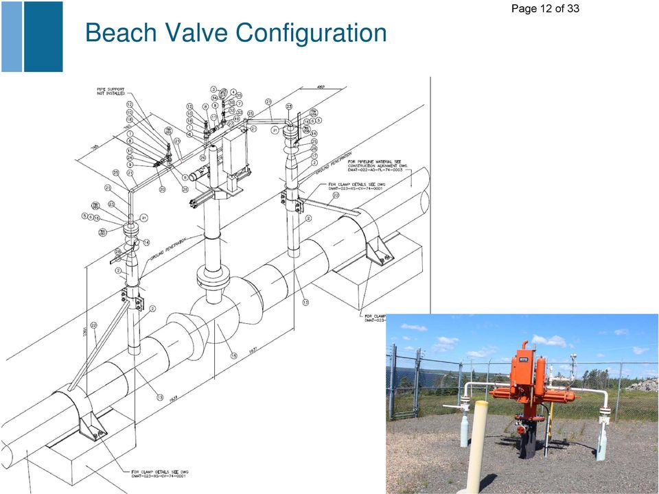
1 DEEP PANUKE Page 1 of 33 TECHNICAL NOTE Topic: Removal of Beach Valve Station Isolation Valve Assembly (P74-SDV-011) Assessment Background: The Deep Panuke gas export pipeline is approximately 175km in length and comprised of an offshore and onshore section. The offshore and onshore pipeline sections are approximately 172.3km and 2.7km in length respectively. The onshore pipeline is located from landfall to the interconnection with the Maritimes and Northeast Pipeline (M&NP). The pipeline has two onshore facilities referred to as the Beach Valve Station (BVS) and Gas Export Pipeline Terminus (GEPT). The BVS is located at landfall and contains a valve (i.e. P74- SDV-011), which can be opened or closed either remotely via the PFC or locally by an individual on site. The GEPT is located adjacent to the M&NP facility and contains a pig receiver and a valve (i.e. P74-SDV-021) which can be opened or closed either remotely via the PFC or locally by an individual on site. The valves are opened or closed via a gas over hydraulics actuator. Details of the onshore pipeline and facilities are located in document DMEN-O22-PD-PR P&ID Onshore Pipeline, Beach Valve Station and GEP Terminus which is located in Appendix A. A plan view of the onshore facilities and pipeline right of way locations is located in Appendix B. An isometric view of the beach valve station assembly above and below grade piping is located in Appendix C. On April 23, 2014, an in-line inspection tool was launched from the offshore Production Field Center (PFC) with an expected arrival at the gas export pipeline 02U 18-Jun-14 Issued for Use D. Trask K. Tonn H. Farrell K. Tonn 01R 16-Jun-14 Issued for Review D. Trask K. Tonn H. Farrell K. Tonn Rev. Date Reason for Issue Prepared Checked Approved Approved Title: Removal of Beach Valve Station Isolation Valve Assembly (P74-SDV-011) Assessment DM EN O22 TN PL U Project Originator Location Type Disc. System No. Rev. This document is the property of EnCana Corporation who will safeguard its rights according to the civil and penal provisions of the law.
 and Gas Export Pipeline Terminus (GEPT). The BVS is located at landfall and contains a valve (i.e. P74- SDV-011), which can be opened or closed either remotely via the PFC or locally by an individual on site.")
2 DEEP PANUKE Page 2 of 33 terminus onshore receiver of April 24, At approximately 10:45 am on April 24, 2014, the inline inspection tool arrived at the beach valve station; however, the tool did not arrive at the onshore receiver and was subsequently confirmed to have stopped at the beach valve assembly. The approximate tool location was determined to be upstream of the first 6-inch tee based upon the receiving the 22Hz transmitter signal from the Wavetrack device located on the inline inspection tool. On June 11, 2014, digital radiography was performed on the excavated pipe section which has confirmed that the inline inspection tool is located upstream of the first 6-inch tee as illustrated in Appendix D. Discussion Inspection Tool Removal Plan Encana has now concluded that it is highly unlikely that the in-line inspection tool will become dislodged on its own and is now planning to remove the in-line inspection tool by performing on-line isolation and cut-out. The proposed removal plan involves performing line isolation both upstream and downstream of the beach valve assembly, removing the beach valve assembly (complete with in-line inspection tool) and re-installing a straight section of linepipe. The planned steps include the following: Weld on split tee fittings (both upstream and downstream of beach valve assembly) rated to the approved pipeline maximum operating pressure (MOP) Weld on purge and equalization fittings Perform hot tap through fittings Insert double isolation (ie. T.D. Williamson - Stopple Train) both upstream and downstream of the beach valve assembly Depressurize and gas free isolated section Cut and remove the beach valve assembly which includes from a location upstream of the inline inspection tool and downstream of the second 6- inch tee as illustrated in Appendix E. Install new straight section of linepipe and oxygen free Remove isolations (i.e. TDW Stopple Train) Install completion plugs and blind flange assembly on hot tap locations The target date for the removal of the beach valve assembly (complete with inline inspection tool) is September Once removed, surplus certified linepipe will be used to reinstate the gas export pipeline. DM EN O22 TN PL U Project Originator Location Type Disc. System No. Rev. This document is the property of EnCana Corporation who will safeguard its rights according to the civil and penalty provisions of the law.

3 DEEP PANUKE Page 3 of 33 Due to required procurement lead times, new valve and extruded headers (tee section) would be unable to be procured in time to re-install in the line during the anticipated September 2014 line isolation program. Since the Deep Panuke gas export pipeline is currently considered Class 1 in accordance with CSA Z662-11, the isolation valve at the beach valve station is not required. A detailed discussion on the requirement of the beach isolation valve is contained in the next section. In the event that future development adjacent to the onshore pipeline occurs, which requires the class of pipeline to be changed to Class 2, the isolation valve will be reinstated with a similar line isolation methodology. The line isolation would not require a new hot tap but rather a re-entry would be performed via the existing hot tap locations. Discussion Requirement for Beach Isolation Valve (P74-SDV-011) The onshore pipeline is located within an industrial park and CSA Z662 (Section 4.3.3, Table 4.1, Note 2) requires that If it is likely that there will be future development in the class location assessment area sufficient to increase the class location designation, consideration shall be given to designing, pressure testing, operating, and maintaining the pipeline in accordance with the requirements applicable to the higher class location. During the design phase of the onshore pipeline, both a petrochemical and a LNG import terminal were proposed to be located adjacent to the onshore pipeline route by Keltic Petrochemical and Maple LNG. As a result, if these developments were built, the Deep Panuke pipeline would be a Class 2 designation. Thus as these proposed developments were under consideration at the time of the development application and possibly could be approved, it was decided to design the onshore pipeline for Class 2 requirements. This would require a maximum valve spacing of 25km for the onshore pipeline section in accordance with Table 4.7. As a result, valve P74-SDV-011 was installed at the landfall location on the assumption that these projects would proceed. Subsequent to the onshore pipeline design phase, both the Keltic Petrochemical and Maple LNG import facility projects have been cancelled and no development has occurred. As a result, the Deep Panuke pipeline is currently Class 1 in accordance with CSA Z662-11, and the isolation valve at the beach valve station is not required as described in the following sections. DM EN O22 TN PL U Project Originator Location Type Disc. System No. Rev. This document is the property of EnCana Corporation who will safeguard its rights according to the civil and penalty provisions of the law.

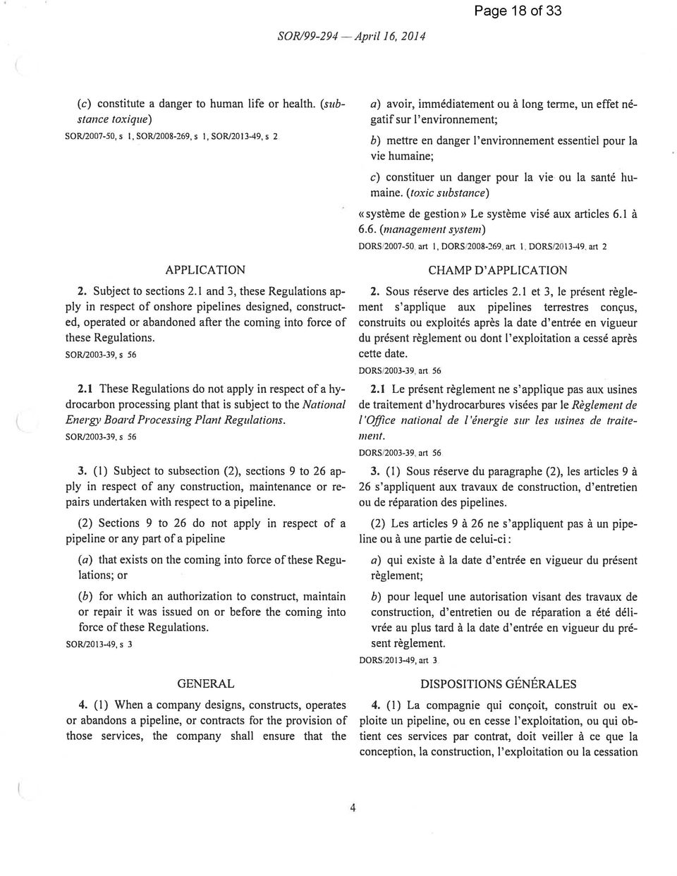
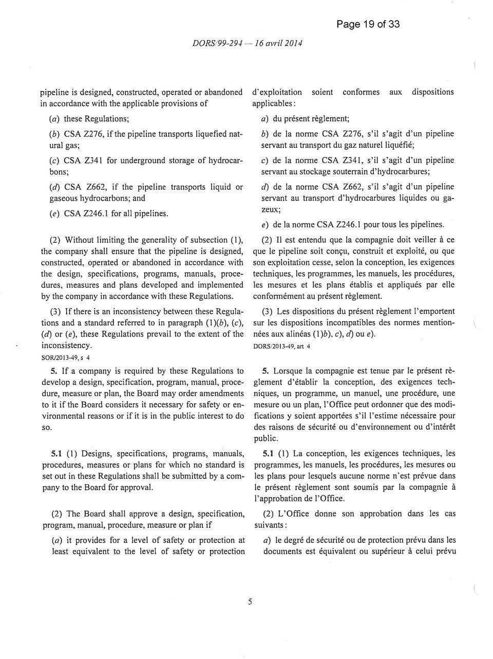
4 DEEP PANUKE Page 4 of 33 Regulatory Requirement: The onshore pipeline section is regulated by the National Energy Board (NEB) in accordance with the Onshore Pipeline Regulations. The Onshore Pipeline Regulations (OPR) have no specified requirement for valve locations and spacing; however, Section 4(1) states that the pipeline is required to be designed, constructed, operated or abandoned in accordance with CSA Z662. Section 42 of the NEB Onshore Pipeline Regulations state: If the class location of a section of a pipeline changes to a higher designation that has a more stringent location factor, the company shall, within six months after the change, submit the proposed plan to deal with the change to the Board. (See Appendix F for OPR Section 4(1) and 42). In addition, a variance of Certificate GC-111 in accordance with Section 21 of the NEB Act is required in order to remove this valve. CSA Z662 Requirement: The Deep Panuke onshore pipeline has been designed, constructed and installed in accordance with CSA Z662 as per the OPR. Section 4.4 of CSA Z662 (See Appendix G) provides requirements for isolation valve location and spacing and states that Isolating valves shall be installed for the purpose of isolating the pipeline for maintenance and for response to operating emergencies. The number and spacing of these valves must comply with Table 4.7 or otherwise can be determined by an engineering assessment. Table 4.7 specifies the maximum valve spacing based upon the type of pipeline and class location. The class location is specified in Section 4.3.2; in particular, Table 4.1. The current type of pipeline and Class location for Deep Panuke is as follows: Type of Pipeline = Gas Class Location Designation = Class 1 DM EN O22 TN PL U Project Originator Location Type Disc. System No. Rev. This document is the property of EnCana Corporation who will safeguard its rights according to the civil and penalty provisions of the law.

5 DEEP PANUKE Page 5 of 33 Note: The basis for Class 1 is that currently no dwellings, building, outside occupied areas or industrial installation are located along the onshore pipeline route. The onshore pipeline is located within an industrial park and the only nearby structures present are three (3) wind turbines for which with no persons are present during normal use. Thus in accordance with Table 4.7, for a gas pipeline with Class 1 designation, there is no code requirement with regards to isolation valve locations and spacing based upon the current development status near the onshore pipeline route. Safety Considerations: Encana has requested that PSRM Services perform a technical review of the Onshore Safety Concept Analysis and other relevant project documentation to determine the potential impact to the Project Target Levels of Safety (TLS) from continued operations based upon current land use in the Goldboro area on the basis that the beach isolation valve (P74-SDV-011) is removed. The review concluded that the project remains within acceptable limits for the Deep Panuke Target Level of Safety, applicable land use risk acceptability criteria for Goldboro and the industry accepted ALARP range; therefore, no risk reduction recommendations have been deemed necessary. This technical review is located in Appendix H. Discussion Future Requirement for Isolation Valve (P74-SDV-011) Since the onshore pipeline is located in an industrial park, there is a potential for a change to Class 2 if an industrial installation or building occupied by 20 or more persons during normal use is situated next to the onshore pipeline as per CSA Z662 Table 4.1. Currently, an LNG import terminal is being proposed for the Goldboro industrial park with the earliest in-service date of In the event that the LNG export facility (or any other future facilities) are approved for construction and is situated next to the onshore pipeline such that it would increase the class location designation, then the beach isolation valve will be necessary. The existing isolation valve assembly will be reinstated, with a similar line isolation methodology. The line isolation would not require a new hot tap but rather a reentry via the existing hot tap locations. DM EN O22 TN PL U Project Originator Location Type Disc. System No. Rev. This document is the property of EnCana Corporation who will safeguard its rights according to the civil and penalty provisions of the law.

6 DEEP PANUKE Page 6 of 33 Encana will continue to monitor future developments in the industrial park to determine if they will result in a class location designation change. In the event that a change occurs and a beach isolation valve is required, the required components will be procured and installed. Conclusions and Recommendations The Deep Panuke gas export pipeline is currently considered as Class 1 in accordance with CSA Z662-11, and thus no beach isolation valve is required. In addition, a technical review of the onshore Concept Safety Analysis was performed and concluded that Deep Panuke remains within acceptable limits for the Target Levels of Safety if the beach isolation valve is removed. As a result, the plan to remove the beach isolation valve assembly (complete with inline inspection tool) and replace with an existing certified linepipe section is considered acceptable. However, a variance of Certificate GC-111 in accordance with Section 21 of the NEB Act is required in order to remove this valve. Encana will continue to monitor the future developments in the industrial park to determine if they will result in a class location designation change. In the event that a class location change occurs and a beach isolation valve is required, the required components will be procured and installed. The isolation valve assembly would be reinstated with a similar line isolation methodology. The line isolation would not require a new hot tap but rather a re-entry via the existing hot tap locations. DM EN O22 TN PL U Project Originator Location Type Disc. System No. Rev. This document is the property of EnCana Corporation who will safeguard its rights according to the civil and penalty provisions of the law.

7 DEEP PANUKE Page 7 of 33 Appendix A Onshore Pipeline, Beach Valve Station and GEP Terminus P&ID DM EN O22 TN PL U Project Originator Location Type Disc. System No. Rev. This document is the property of EnCana Corporation who will safeguard its rights according to the civil and penalty provisions of the law.

8 Page 8 of 33

9 DEEP PANUKE Page 9 of 33 Appendix B Onshore Pipeline and Facilities Overview DM EN O22 TN PL U Project Originator Location Type Disc. System No. Rev. This document is the property of EnCana Corporation who will safeguard its rights according to the civil and penalty provisions of the law.

10 Page 10 of 33 M&NP METERING FACILITY Encana GAS EXPORT PIPELINE TERMINUS FACILITY SOEP GAS PLANT WINDFARM INDUSTRIAL PARK BOUNDARY GOLDBORO INDUSTRIAL PARK Betty s Cove Brook DEEP PANUKE ONSHORE PIPELINE R.O.W. EXXON MOBILE ONSHORE PIPELINE R.O.W. BEACH VALVE STATION

11 DEEP PANUKE Page 11 of 33 Appendix C Beach Valve Assembly Isometric DM EN O22 TN PL U Project Originator Location Type Disc. System No. Rev. This document is the property of EnCana Corporation who will safeguard its rights according to the civil and penalty provisions of the law.

12 Beach Valve Configuration Page 12 of 33
13 DEEP PANUKE Page 13 of 33 Appendix D Location of In-Line Inspection Tool DM EN O22 TN PL U Project Originator Location Type Disc. System No. Rev. This document is the property of EnCana Corporation who will safeguard its rights according to the civil and penalty provisions of the law.

14 Page 14 of 33

15 DEEP PANUKE Page 15 of 33 Appendix E Beach Valve Assembly Cut Locations DM EN O22 TN PL U Project Originator Location Type Disc. System No. Rev. This document is the property of EnCana Corporation who will safeguard its rights according to the civil and penalty provisions of the law.

16 Page 16 of 33

17 DEEP PANUKE Page 17 of 33 Appendix F OPR Section 4(1) and 42 DM EN O22 TN PL U Project Originator Location Type Disc. System No. Rev. This document is the property of EnCana Corporation who will safeguard its rights according to the civil and penalty provisions of the law.

18 Page 18 of 33
19 Page 19 of 33
20 Page 20 of 33

21 DEEP PANUKE Page 21 of 33 Appendix G CSA Z Isolation Valve Spacing Requirements DM EN O22 TN PL U Project Originator Location Type Disc. System No. Rev. This document is the property of EnCana Corporation who will safeguard its rights according to the civil and penalty provisions of the law.
22 Page 22 of 33
23 Page 23 of 33
24 Page 24 of 33
25 Page 25 of 33
26 DEEP PANUKE Page 26 of 33 Appendix H Technical Review of Onshore Concept Safety Analysis DM EN O22 TN PL U Project Originator Location Type Disc. System No. Rev. This document is the property of EnCana Corporation who will safeguard its rights according to the civil and penalty provisions of the law.
27 PSRMServices Page 27 of 33 Technical Review of the Onshore Concept Safety Analysis Removal of Beach Valve Station Isolation Valve Assembly (P74 SDV 011) The below text provides the technical review and support, for the continued operation of the onshore Deep Panuke facility with the removal of beach valve P74 SDV 011. The below review confirms that the Deep Panuke onshore facility will remain within both the Project Target Levels of Safety and the applicable land use risk acceptability criteria for Goldboro and the industry accepted ALARP range if the beach valve is removed and that no risk reduction recommendations have been deemed necessary. A previous technical review was conducted to confirm that the Deep Panuke facility could operate safely without a functioning beach valve; that review confirmed that in effect the Projects Target Levels of Safety were not affected by the functionality of the valve given the occupancy of the surrounding areas. Introduction On April 23rd, 2014, an in line inspection tool was launched from the PFC and the expected arrival at the gas export pipeline terminus onshore receiver was April 24th, The tool did not arrive at the onshore receiver and was subsequently confirmed to have stopped at the beach valve assembly. Digital radiography was performed on the excavated pipe section which confirmed that the inline inspection tool was located just upstream of the first 6 tee. Previous problems with beach valve P74 SDV 011 had already prompted a review of the Deep Panuke onshore pipeline and functionality of the beach valve actuator and concluded that the function (and hence presence) of the valve did not affect the Project Target Levels of Safety. Further it has been proposed that since the Deep Panuke gas export pipeline is currently considered Class 1 in accordance with CSA Z662 11, the isolation valve at the beach valve station is not required per regulation. As the Class 1 designation is contingent on the absence of adjacent industry, it is acknowledged that in the event that future development adjacent to the onshore pipeline occurs which could result in a change in the class of the pipeline, the isolation valve could be reinstated with a similar line isolation methodology to the removal. From a safety perspective the prior review which considered the impact on the Project Target Levels of Safety from an inoperable beach valve P74 SDV 011 is very similar to the proposed removal case. As such, this review will look at the Concept Safety Analysis (DMAE X00 RP LC R completed by ESR Technology, July 2011) and other relevant project documentation to determine the potential impact to the Project Target Levels of Safety (TLS) from continued operation without the ability to isolate the gas export pipeline at the beach. The approach to this technical review is to take a high level look at the data (typical input parameters which ESR would have used in developing their QRA leak frequency, isolation, ignition frequency and type, population/occupancy, hazard range/effect, etc ) which form the basis for the individual risk for the onshore project to confirm the relative impact which would be seen from removing the isolation valve and associated assembly at the beach valve location. Note that within the current QRA (Concept Page 1 of 7
28 PSRMServices Page 28 of 33 Safety Analysis Section 5 QUANTITATIVE RISK ASSESSMENT OF ONSHORE RELEASES) there are numerous conservative assumptions which have now been eliminated (due to other adjacent projects being cancelled) and a factor of failure (9%) was already placed on this beach valve. The focus of this review will be the risk to personnel in line with the Concept Safety Analysis identified hazards and in accordance with the Project TLS and land use criteria. Note that the Concept Safety Analysis did look at environmental risk as well but during the hazard identification process no high risks to the environment were identified. Given the noted CSA evaluation of environmental risk and that this is a natural gas pipeline system with no liquids nor hazardous levels of H 2 S we have not considered environmental risk further in this review. Acceptance Criteria The Target Levels of Safety (TLS) for the Deep Panuke facilities are defined in the Design Memorandum, and are summarized in Table 1. No. Description Target Level of Safety (freq./year) 1 Individual Risk <1 x Group Risk (based on 68 POB) <1.36 x 10 3 ( 10 fatalities per year) <2.72 x 10 4 ( 50 fatalities per year) 3 Environmental Risk ALARP 4 Production Facility Impairment (includes TLS for PFC primary structure, TR impairment frequency, escape route and evacuation system) Table 1: Target Levels of Safety <1 x 10 3 Loss of integrity to the installation s key safety functions from all major accident events. <1 x 10 4 Loss of integrity to the installation s key safety functions from any single major accident events. The onshore facilities at Goldboro are also subject to the Major Industrial Accident Council of Canada risk acceptability criteria summarized below in Table 2. Intolerable Grey Insignificant Table 2: Land Use Criteria Individual Specific Risk (ISR) > 10 4 pa 10 6 < ISR < 10 4 pa < 10 6 pa Technical Sensitivity Review The approach taken in this review is to consider the key components which go into defining the Location Specific Individual Risk (LSIR) and Individual Risk (IR) values and for each one to consider whether the beach valve has any bearing on the assessment and if it does to determine to what extent its removal would affect the contributing risk value. Page 2 of 7
29 PSRMServices Page 29 of 33 The starting points are the hazard cases to be considered, these are defined within the CSA (see the below two bullets). Since the concentration of hydrogen sulphide in the export gas does not exceed 4ppm, the major hazards associated with releases from the onshore facilities were considered in the QRA as being: Immediate ignition leading to a jet fire Delayed ignition leading to either a flash fire or a vapour cloud explosion, burning back to a jet fire. Our focus is the risk to individuals; as such we are looking at the events which would lead to personnel being within the hazard envelope of a flash fire or jet fire heat flux with lethal doses (Note: vapor cloud explosion was considered in the original FEED QRA, this is discounted now and explained below). When considering the event potential from a QRA perspective we would have three starting cases. 1. Event failure (release frequency) with NO ignition. 2. Event failure (release frequency) with immediate ignition. 3. Event failure (release frequency) with delayed ignition. Note that the distance from surrounding facilities to the beach valve is not the main factor with regards to the risk contours. It is the leak source proximity to the SOEP Gas Plant and M&NP Metering Facility that dictates the risk contour arrangement. The leak source is considered as the base input to the QRA as being an assumed frequency per unit length for the pipeline section and based on part counts for the beach valve location and the Terminus (next to the M&NP Metering Facility). As such, worst case scenarios (rupture) have been assumed at all points along the onshore pipeline section from the beach valve to the Terminus. The greatest risk to the SOEP Gas Plant facility from the Gas Export Pipeline (GEP) system would come from the points closest to the SOEP, based on their assumed likelihood of failure with consequence radii that could impact the SOEP for small, large and rupture cases. This defines the location specific individual risk and the group risk would then need to account for likelihood of occupancy in that area reaching the levels required to exceed the set group risk criteria. The QRA risk contours are based on small, large and rupture case events. The risk contours take these entire event cases combined to form the individual risk contours provided within the CSA. If we were to focus on worst case alone, breaking out the individual risk contour for just the rupture case, this would mean we consider only a small portion of the contributing risk to personnel and the risk contour would reduce. For example, if we look at the risk contours corresponding to the individual risk considering just the worst case scenario (rupture), they do not cross the existing SOEP Gas Plant boundary at the levels dictated by our Target Levels of Safety for Individual Risk (<1 x 10 3), and will remain compliant with the Land Use Criteria of < 10 6 pa (per annum) for Individual Specific Risk. Group risk has not been considered in the original QRA and ESR CSA update as the pipeline and onshore facilities are not within a populated area and the onshore facilities are normally unmanned. Page 3 of 7
30 PSRMServices Page 30 of 33 As mentioned the area is predominantly unmanned and hence detection and action would normally rely on the pipeline leak detection system. The CSA assumed that the pipeline leak detection system was capable of detecting leaks of 2% normal steady flow and greater. Based on the pipeline leak detection system in place the design QRA also assumed that full ruptures would be detected in 5 minutes, 10% leaks in 10 minutes, 5% leaks in 25 minutes and 2% leaks in 50 minutes. As immediate ignition is assumed to occur within 5 minutes and all delayed ignition occurs after 5 minutes, and given that it is considered unlikely that any leak from our system would be detected within 5 minutes, it is assumed that all immediate ignition cases will occur before there would be any remote or manual attempt to close the beach valve if present. The isolated nature of the location and lack of human presence in the immediate surrounding areas further supports this assumption. As such, all immediate ignition cases will happen regardless of whether the beach valve is installed and functioning or not installed and therefore has no impact on whether the beach valve is provided or not. In support of the above statement, it has been considered that without isolation the inventory of the subsea pipeline is greater than the isolated onshore pipeline section and therefore the leak release conditions will decay much slower than a smaller isolated inventory. However, in our assessment we consider all factors of risk including likelihood which addresses the occupancy of the area and the reaction of personnel, not just the consequence envelope. Additionally for immediate ignition the impacted area will be at it s greatest with the highest pressure, at the start of the release. This is the same for both cases whether isolation is achieved or not in fact this is the same for a period of 5 minutes in the case of a full rupture which is the time considered by the QRA and CSA for action to be taken to remotely close the beach valve (10 minutes for leaks of 10% volume and 25 minutes for leaks of 5% volume). As we have immediate ignition we are dealing with jet fire cases only and as per the QRA and CSA all immediate ignition cases are assumed to occur within 5 minutes. As isolation was not considered by the QRA to occur within 5 minutes and considering that all immediate ignition cases occur within 5 minutes, the immediate event would be the same regardless of whether the beach valve is functional and present or not. The QRA and CSA assume that jet fire cases will result in 100% fatality at 37.5 kw/m2, 50% fatality at 25 kw/m2, 10% fatality at 12.5 kw/m2 and 1% fatality at 9.5 kw/m2. The only differences in consequence from having an isolating beach valve compared to no isolation are that the jet fire exposure area will not reduce as quickly. However, it is important to note that the consequence envelope will not increase, we do not consider that people will walk into the jet fire envelope, we have no temporary refuge buildings where we the jet fire could become an issue for trapped personnel, all areas provide relatively free access for escape of any individual that is in the area and not affected by the initial immediate ignition jet fire event. Also note that the QRA and CSA show that immediate ignition events dominate the risk accounting for 78% of the risk profile. As such and as noted the functionality of the beach valve therefore can only have an impact on the remaining 22% of the risk profile (discussed in the next few paragraphs). Following on from the above reasoning if there is no ignition, then there is no consequence and no risk. As such, the only cases where the function of the beach valve could have an impact on our risk levels are the delayed ignition events. Page 4 of 7
31 PSRMServices Page 31 of 33 Considering just the delayed ignition events it was already assumed that the beach valve would fail for 9% of demands. This means we are looking at the impact from changing the basis of this remaining 91% to reflect that the beach valve has been removed. Explosion events were considered in the FEED and design QRA, these were predominantly associated with the potential congestion of the Maple LNG Facility. As neither the Maple LNG Facility nor the Keltic Petrochemical Facility materialized, the explosion events associated with the locations have no relevance to the beach valve removal or not. The CSA did consider within the consequence section that there were potential noted congested areas within the SOEP Gas Plant. The area considered is located at 480 m from the gas export pipeline. The maximum LFL range considered was 550 m for LFL and 834 m for ½ LFL. The QRA considers that these levels are achieved at a leak flow rate of 5240 kg/s which is the maximum instantaneous rupture release case seen. This release rate decays rapidly and the predicted release rate after 2 minutes (un isolated as no isolation is assumed to occur before 5 minutes) would have dropped to 63 kg/s as referenced in the QRA. At this flow rate the release case produces a maximum LFL range of 78 m and a maximum ½ LFL range of 137 m. The CSA goes on to state in section that Since the initial rupture release rate of 5240 kg/s decays very rapidly and would lead to very pessimistic hazard ranges, it is more reasonable to use the average release rate over the first 2 minutes (879 kg/s in the case of ruptures) when assessing the immediate ignition jet fires, whether isolated or not. For the delayed ignition cases, the release rate will depend on whether or not the release is isolated. It is reasonable to consider delayed ignition as taking place after 5 minutes, corresponding to an isolated rupture release rate of 0.7 kg/s. Later ignition would result in even smaller isolated release rates. In the case of un isolated, delayed ignition rupture releases, we conservatively use the normal operational flow rate of 74 kg/s, although it is unlikely that normal flow rate could in reality be sustained following a rupture. For unisolated, delayed ignition large and small leaks, we use the release rate after 2 minutes, as compared to after 5 minutes for the isolated, delayed ignition leaks. Based on the above the CSA and the QRA did not consider the consequence envelope associated with the instantaneous release rate of 5240 kg/s due to the rapid decay and, we assume, inability to sustain the cloud volume. They considered instead a conservative basis for the consequence modelling input to the risk calculation of un isolated delayed ignition cases as being based on the continuous volumetric flow rate from the platform. This case would produce an LFL and ½ LFL radii similar to the 63 kg/s case previously noted and are well outside of the 480 m spacing between the GEP and the SOEP congested areas. As such the CSA and QRA did not consider within the risk calculations delayed ignition cases which could have reached the SOEP congested areas. Given that the Maple LNG Facility along with the Keltic Petrochemical Facility did not materialize and as the SOEP facility was considered within the QRA as having no potential for vapour cloud explosion (blast overpressure effects) there are no other congested areas left within the LFL range for the structures present today (tree s in the area are routinely cleared). This further reduces the events that could be affected by the beach valve removal. This also removes the vast majority of the risk associated with the pipeline failure cases and essentially all of the risks from the beach valve removal as the areas within the range of hazard envelopes predicted by the consequence modelling are now unmanned and restricted access. Page 5 of 7
32 PSRMServices Page 32 of 33 The main remaining difference is from an un isolated delayed ignition event around the SDV and pig receiver location where a failure to isolate the beach valve will result in a prolonged release rate higher than for the isolated case. Hence the hazard envelope will be slightly larger and when we consider the probability of being exposed to the hazard effect we have a slightly increased area to consider. Isolation Hole Category Hole Size (m) Release Rate at Ignition (kg/s) Isolated Small Un isolated Small Isolated Large Un isolated Large Isolated Rupture Un isolated Rupture Table 3: Onshore Export Pipeline Release Rates for Delayed Ignition Case Based on the above and the QRA assessment consequence data, jet fire hazard ranges to critical heat flux levels for flow rates of 0.7 kg/s and lower do not generate a lethal heat dose. As such isolation of the beach valve or no isolation of the beach valve will have no impact to the individual risk from small release cases and jet fire hazard events. The same applies to the LFL cases and flash fire events for small leaks. As small leak cases contribute 80% of the leak frequencies overall and 90% for the main SDV and pig receiver location this finding further reduces the impact that the beach valve has on the target levels of safety for the onshore facility. Additionally the hazard envelopes for the large hole categories that equate to the difference in release rate amount to an approximate 20% increase in hazard envelope size. To be conservative we have factored a 100% increase into our assessment over the contributing risk from the large cases. Given the significant difference between flow rates for the rupture case we have considered 100% fatality from the delayed ignition cases this area is the most noticeable impact from removal of the beach valve but contributes only a small amount to the overall risk for the facility. It should also be mentioned now that there are a very small percentage of leaks which would go undetected and still contribute to the hazard events which would determine the risk for the facility. For these undetected leaks the provision of a beach valve or not has no impact on the event outcomes (as with no detection there is no action to close the valve) and hence would not factor into this comparison. As mentioned above, now that the Maple LNG Facility along with the Keltic Petrochemical Facility have been cancelled the beach valve area and onshore piping section upto the SDV and pig receiver location adjacent to the M&NP Custody Transfer Station has effectively no normal personnel activity or presence and no public exposure (other than intruders for which signage has been posted). As such these two areas contribute very little to the overall individual risk for the Onshore facility which makes the main focus the SDV and pig receiver location where personnel attendance may be required and where the Terminus has its closest proximity to the adjacent M&NP custody transfer station. Further it should be considered that as a result of removing the beach valve and all associated instrument tubing we would be decreasing the overall risk associated with leak sources from that location. Page 6 of 7
33 PSRMServices Page 33 of 33 If we were to consider that 100% of all resultant delayed ignition events (based on the prior qualifications and discounted events) around the SDV and pig receiver location were to result in fatality, and ignore any potential risk reduction from removal of leak paths associate with the beach valve, we would pessimistically change the LSIR (Location Specific Individual Risk) from 6.1 X 10 6 per year to approximately 9 X 10 6 per year. This is an increase in overall location specific individual risk at this location of over 150% and contains a number of conservative assumptions. Such a conservative basis would result in an equivalent IR of 1.8 X 10 7 per year. This level of individual risk is still well below the widely accepted ALARP level of 1 X 10 6 per year and would be classified as insignificant in accordance with the Major Industrial Accident Council of Canada land use risk acceptability criteria. This level also falls well below the Encana Project Individual Risk (IR) Target Level of safety of <1 x This sensitivity study is based on very conservative assumptions; a more detailed assessment would further reduce the difference between the IR levels seen when comparing the effect of removing the beach valve from the gas export pipeline. This technical review indicates that the removal of the beach valve will not impact the Project Target Levels of Safety or the more stringent land use criteria. Yours Sincerely, Colin Sewell Managing Director 19 th June 2014 Page 7 of 7
Consequence Analysis: Comparison of Methodologies under API Standard and Commercial Software
 511 A publication of CHEMICAL ENGINEERING TRANSACTIONS VOL. 36, 2014 Guest Editors: Valerio Cozzani, Eddy de Rademaeker Copyright 2014, AIDIC Servizi S.r.l., ISBN 978-88-95608-27-3; ISSN 2283-9216 The
The SPE Foundation through member donations and a contribution from Offshore Europe
 Primary funding is provided by The SPE Foundation through member donations and a contribution from Offshore Europe The Society is grateful to those companies that allow their professionals to serve as
QUANTITATIVE RISK ASSESSMENT - QRA FOR
 QUANTITATIVE RISK ASSESSMENT - QRA FOR TOWN GAS COMPANY PART - II Pressure Reduction and Odorant Station at Greater Cairo Jan 2006 Report # PS-GZT-TG 001 Rev.0 PS-GZT-TG-001 Revision (1) Jan 2006 Table
SOCALGAS APROACH TO PIPELINE INTEGRITY
 SUMMER 2011 SOCALGAS APROACH TO PIPELINE INTEGRITY Southern California Gas Company (SoCalGas ) is committed to providing clean, safe and reliable natural gas to its customers and takes important steps
Enbridge Class Location Change Management Plan. 1.1 Additional Information for Identified Changed Class Locations
 Information Request No. 1-1.1 Additional Information for Identified Changed Class Locations Reference: i. (A70936) Preamble: ii. Canadian Standards Association (CSA) Z662-15, Oil and Gas Pipeline Systems
The Pipelines Regulations, 2000
 PIPELINES, 2000 P-12.1 REG 1 1 The Pipelines Regulations, 2000 being Chapter P-12.1 Reg 1 (effective April 1, 2000) as amended by the Statutes of Saskatchewan, 2014, c.21. NOTE: This consolidation is not
NCCER 13614 Progress Blvd., Alachua, FL 32615 Tel: (888) 622-3720 E-mail: info@nccer.org. Task Number Item Date(s) Recorded By
 622-3720 E-mail: info@nccer.org. Task Number Item Date(s) Recorded By") NCCER 13614 Progress Blvd., Alachua, FL 32615 Tel: (888) 622-3720 E-mail: info@nccer.org PIPELINE MAINTENANCE On-the-Job Training Level One MODULE 66101-02 INTRODUCTION TO THE PIPELINE INDUSTRY This is
NCCER 13614 Progress Blvd., Alachua, FL 32615 Tel: (888) 622-3720 E-mail: info@nccer.org PIPELINE MAINTENANCE On-the-Job Training Level One MODULE 66101-02 INTRODUCTION TO THE PIPELINE INDUSTRY This is
HSE information sheet. Fire and explosion hazards in offshore gas turbines. Offshore Information Sheet No. 10/2008
 HSE information sheet Fire and explosion hazards in offshore gas turbines Offshore Information Sheet No. 10/2008 Contents Introduction.. 2 Background of gas turbine incidents in the UK offshore sector...2
All Oil and Gas Companies under the Jurisdiction of the National Energy Board (the Board or NEB) and All Interested Parties
 and All Interested Parties") File 172-A000-73 24 April 2002 To: All Oil and Gas Companies under the Jurisdiction of the National Energy Board (the Board or NEB) and All Interested Parties SECURITY AND EMERGENCY PREPAREDNESS AND RESPONSE
File 172-A000-73 24 April 2002 To: All Oil and Gas Companies under the Jurisdiction of the National Energy Board (the Board or NEB) and All Interested Parties SECURITY AND EMERGENCY PREPAREDNESS AND RESPONSE
INDIAN STANDARDS FOR NATURAL GAS PIPELINE SYSTEM
 INDIAN STANDARDS FOR NATURAL GAS PIPELINE SYSTEM 1. IS 15663(Part 1):2006 This code covers requirements and recommendations for the design, materials, construction and testing of pipelines made of steel
Technical Specifications For The Drilling Program
 01U 2008-10-03 Issued for Use D. Dixon T. Russell D. Green P. Shankel Rev Date Reason for Issue Prepared Checked Checked Approved Title DR15 - Communications Equipment and Services Drilling Services Prequalification
Regulations for bunkering LNG
 Regulations for bunkering LNG CCNR round table LNG, 13-11-2012 Erik Büthker, chairman of Dutch standards committee LNG refuelling stations Discipline naam [1] Content Ballast Nedam What is a standard,
Ultrasonic Gas Leak Detection
 Ultrasonic Gas Leak Detection What is it and How Does it Work? Because every life has a purpose... Ultrasonic Gas Leak Detection Introduction Ultrasonic gas leak detection (UGLD) is a comparatively recent
Hazard and Risk Assessment
 Appendix C Hazard and Risk Assessment C1 Preliminary Hazard Analysis C2 Kurnell Buncefield Review Appendix 1 Preliminary Hazard Analysis Caltex Refineries (NSW) Pty Ltd Proposed Kurnell Product Terminal
Trenching and Excavation Safety
 1.0 ACTIVITY DESCRIPTION 1.1 This document provides basic safety guidelines related to excavation and trenching in pipeline construction activities. These guidelines are applicable to the locating, marking
Preventing Overheated Boiler Incidents
 Preventing Overheated Boiler Incidents PSE&G Appliance Service October 2012 Runaway Boiler Explosion Review Items Hazard Background Past Incidents PSE&G Emergency Response Future Process Improvements What
Lake Charles Expansion Project
 Lake Charles Expansion Project Resource Report 11 Reliability and Safety Docket No. CP14- - Public Kinder Morgan Louisiana Pipeline LLC 1001 Louisiana Street, Suite 1000 Houston, Texas 77002 June 2014
Gas Standards and Safety. Guidance Note GAS INSTALLATIONS SUPPLIED FROM BIOGAS FACILITIES - ACCEPTANCE REQUIREMENTS GAS ACT 2000
 Gas Standards and Safety Guidance Note January 2015 (GN106) Version 1.0 GAS INSTALLATIONS SUPPLIED FROM BIOGAS FACILITIES - ACCEPTANCE REQUIREMENTS GAS ACT 2000 A guide to assist in the design of biogas
BUILDING A WORLD OF DIFFERENCE. Safe work in confined spaces
 Health & Safety Training Safe work in confined spaces Agenda Introduction What is a confined space? What are the hazards? Safe system of work Emergency arrangements Summary of pre-entry checks Questions
Major Hazard Risk Assessment on Ammonia Storage at Jordan Phosphate Mines Company (JPMC) in Aqaba, Jordan
 in Aqaba, Jordan") Major Hazard Risk Assessment on Ammonia Storage at Jordan Phosphate Mines Company (JPMC) in Aqaba, Jordan Jehan Haddad, Salah Abu Salah, Mohammad Mosa, Royal Scientific Society, Jordan Pablo Lerena, Swiss
Major Hazard Risk Assessment on Ammonia Storage at Jordan Phosphate Mines Company (JPMC) in Aqaba, Jordan Jehan Haddad, Salah Abu Salah, Mohammad Mosa, Royal Scientific Society, Jordan Pablo Lerena, Swiss
On-Site Risk Management Audit Checklist for Program Level 3 Process
 On-Site Risk Management Audit Checklist for Program Level 3 Process Auditor name: Date: I. Facility Information: Facility name: Facility location: County: Contact name: RMP Facility I.D. Phone Number:
Guidelines for Excavations
 O c t o b e r 2 0 0 1 Guidelines for Excavations in the vicinity of gas lines Technical Standards & Safety Authority Putting Public Safety First Guidelines for Excavations in the Vicinity of Gas Lines
CHAPTER 4: OFFSITE CONSEQUENCE ANALYSIS
 CHAPTER 4: OFFSITE CONSEQUENCE ANALYSIS RMP OFFSITE CONSEQUENCE ANALYSIS GUIDANCE This chapter is intended for people who plan to do their own air dispersion modeling. If you plan to do your own modeling,
LNG SAFETY MYTHS and LEGENDS
 LNG SAFETY MYTHS and LEGENDS Doug Quillen ChevronTexaco Corp. Natural Gas Technology Investment in a Healthy U.S. Energy Future May 14-15, 2002 Houston Introduction North America is Becoming the Focal
INSTITUTION OF GAS ENGINEERS AND MANAGERS. Founded 1863 IGEM/TD/2 Edition 2 Royal Charter 1929 Communication XXXX Her Majesty the Queen
 INSTITUTION OF GAS ENGINEERS AND MANAGERS IGEM/TSP/12/156 Founded 1863 IGEM/TD/2 Edition 2 Royal Charter 1929 Communication XXXX Patron Her Majesty the Queen ASSESSING THE RISKS FROM HIGH PRESSURE NATURAL
NATURAL GAS EMERGENCY PROCEDURES AND ACCIDENT PREVENTION
 NATURAL GAS EMERGENCY PROCEDURES AND ACCIDENT PREVENTION Fire and Life-Safety Group (FLS) I. EMERGENCY PROCEDURES The emergency procedures for natural gas emergencies are similar to that for fire emergencies.
GAS DISPERSION WITH OPENFOAM
 GAS DISPERSION WITH OPENFOAM Chris Dixon Major Hazards Management Centre of Expertise October 2012 1 DEFINITIONS AND CAUTIONARY NOTE Resources: Our use of the term resources in this announcement includes
A Job Safety Execution Plan is required. mixtures of the above called, natural gas liquids (NGL's) refined products and their components
 refined products and their components") TITLE Pipelines and Terminals Manual/Volume 3 - SECTION 02: SUBJECT 20: PURPOSE AND SCOPE During the normal lifetime of a pipeline it becomes necessary to add or remove piping, modify existing piping or
TITLE Pipelines and Terminals Manual/Volume 3 - SECTION 02: SUBJECT 20: PURPOSE AND SCOPE During the normal lifetime of a pipeline it becomes necessary to add or remove piping, modify existing piping or
CONFINED SPACES MANAGEMENT PROGRAM (REGIONAL CAMPUSES AND RESEARCH STATIONS)
") CONFINED SPACES MANAGEMENT PROGRAM (REGIONAL CAMPUSES AND RESEARCH STATIONS) January 2007 TABLE OF CONTENTS 1.0 PURPOSE AND SCOPE 1.1 Intent 1.2 Scope 1.3 Program Elements 2.0 REGULATORY REQUIREMENTS 3.0
CONFINED SPACES MANAGEMENT PROGRAM (REGIONAL CAMPUSES AND RESEARCH STATIONS) January 2007 TABLE OF CONTENTS 1.0 PURPOSE AND SCOPE 1.1 Intent 1.2 Scope 1.3 Program Elements 2.0 REGULATORY REQUIREMENTS 3.0
DET NORSKE VERITAS TM
 DET NORSKE VERITAS TM APPENDIX B HAZID REPORT NO./DNV REG NO.: 2013-4091 / 17TLT29-5 REV 1, 11.06.2013 DET NORSKE VERITAS Table of Contents Page 1 BACKGROUND AND SCOPE OF WORK... 2 2 METHODOLOGY... 4 3
How To Make A Pressure Relief Valve
 0510 First Line of Safety: Farris Engineering Our Company Farris Engineering, a business unit of Curtiss-Wright Flow Control Company, has been at the forefront of the design and manufacture of spring-loaded
DET NORSKE VERITAS. Report Corrib Onshore Pipeline QRA. Shell E&P Ireland Ltd. Report no/dnv Reg No.: 01/ 12LKQW5-2 Rev 01, 2010-05-18
 DET NORSKE VERITAS Report Corrib Onshore Pipeline QRA Shell E&P Ireland Ltd. Report no/dnv Reg No.: 01/ 12LKQW5-2 Rev 01, 2010-05-18 DET NORSKE VERITAS Report for Shell E&P Ireland Ltd. Corrib Onshore
How To Safely Dig For Natural Gas
 PNG DIAL B4-U-DIG book_final_nu 5/1/05 3:24 PM Page 2 Phoenix Natural Gas,197 Airport Road West, Belfast BT3 9ED. Tel. 08454 55 55 55. www.phoenix-natural-gas.com PNG DIAL B4-U-DIG book_final_nu 5/1/05
www.klmtechgroup.com TABLE OF CONTENT
 Page : 1 of 13 Project Engineering Standard www.klmtechgroup.com KLM Technology #03-12 Block Aronia, Jalan Sri Perkasa 2 Taman Tampoi Utama 81200 Johor Bahru Malaysia TABLE OF CONTENT SCOPE 2 REFERENCES
Ontario Fire Code SECTION 5.13 DIP TANKS. Illustrated Commentary. Office of the Ontario Fire Marshal
 Ontario Fire Code SECTION 5.13 DIP TANKS Illustrated Commentary Office of the Ontario Fire Marshal Dip Tanks Illustrated Commentary 1 5.13.1. Location 5.13.1.1. Dip tank operations involving flammable
Proposed Development Phase IV at CRC Oil Terminal, Tsing Yi - Refrigerated Storage Tanks for Liquefied Gas
 in association with China Resources Petrochems (Group) Co. Ltd Proposed Development Phase IV at CRC Oil Terminal, Tsing Yi - Refrigerated Storage Tanks for Liquefied Gas Project Profile July 2005 CONTENTS
Using the Linear Risk Integral (LRI) approach in pipeline QRA for a better application of risk mitigation measures
 approach in pipeline QRA for a better application of risk mitigation measures") Using the Linear Risk Integral (LRI) approach in pipeline QRA for a better application of risk mitigation measures Urban Neunert, ILF Consulting Engineers, Germany Abstract Minimizing the risks resulting
Using the Linear Risk Integral (LRI) approach in pipeline QRA for a better application of risk mitigation measures Urban Neunert, ILF Consulting Engineers, Germany Abstract Minimizing the risks resulting
Implementing New Technology at TransCanada Meter Stations -- Better, Faster, Cheaper
 2001 Canadian Gas Association Gas Measurement School Winnipeg, Manitoba Implementing New Technology at TransCanada Meter Stations -- Better, Faster, Cheaper Prepared by: Dean Mah, P.Eng. Warren Peterson
ASK THE EXPERT: Burner Troubleshooting Information & Maintenance
 ASK THE EXPERT: Burner Troubleshooting Information & Maintenance The burner is the heart of your BBQ. It is subject to a number of conditions that can cause damage, and lead to potential safety issues.
Using CFD in Platform Design
 Using CFD in Platform Design Eric Peterson, PhD. Principal Consultant Quantitative Risk Analyst Scandpower Inc., Houston,TX Hans Nordstand, Scandpower Inc., Houston, TX Sverre Nodland, Scandpower Inc.,
MSC/Circ.1002 26 June 2001 GUIDELINES ON ALTERNATIVE DESIGN AND ARRANGEMENTS FOR FIRE SAFETY
 INTERNATIONAL MARITIME ORGANIZATION 4 ALBERT EMBANKMENT LONDON SE1 7SR Telephone: 020 7735 7611 Fax: 020 7587 3210 Telex: 23588 IMOLDN G IMO E Ref. MSC/Circ.1002 26 June 2001 GUIDELINES ON ALTERNATIVE
ANNUAL OFFSHORE STATISTICS & REGULATORY ACTIVITY REPORT 2013/2014
 ANNUAL OFFSHORE STATISTICS & REGULATORY ACTIVITY REPORT 2013/2014 Date of release: December 2014 1 Preface HSE is responsible for regulating health & safety matters offshore. The Health and Safety at Work
Chapter 10. Flow Rate. Flow Rate. Flow Measurements. The velocity of the flow is described at any
 Chapter 10 Flow Measurements Material from Theory and Design for Mechanical Measurements; Figliola, Third Edition Flow Rate Flow rate can be expressed in terms of volume flow rate (volume/time) or mass
Emergency Plan. This emergency plan provides a format of data essential in an emergency situation.
 Emergency Plan A. Introduction This emergency plan provides a format of data essential in an emergency situation. B. Definition of Emergency Incident An emergency condition exists when we determine that
ASME B31.3 Process Piping. Scope of B31.3 Course
 ASME B31.3 Process Piping Charles Becht IV, PhD, PE Don Frikken, PE Instructors BECHT ENGINEERING COMPANY, INC. Introduction -1 Scope of B31.3 Course This course covers piping as typically used in process
Distributed CNG and LNG as sources of natural gas in New England
 Distributed CNG and LNG as sources of natural gas in New England Prepared for OsComp Systems May 15, 2013 C o n c e n t r i c E n e r g y A d v i s o r s a n d i t s l o g o a r e f e d e r a l l y r e
Pressurised Pipeline Repair or Modification Enabled by Double Block And Bleed Isolation Tools
 STATS GROUP Process & Pipeline Integrity Solutions Pressurised Pipeline Repair or Modification Enabled by Double Block And Bleed Isolation Tools Dale Millward Director EPRS & Subsea Services Presentation
Millersville University - Office Of Environmental Health & Safety Scope & Application
 Confined Space Entry Millersville University - Office Of Environmental Health & Safety Scope & Application The Confined Space Entry (CSE) program applies to the safe working practices for entering and
10 Nuclear Power Reactors Figure 10.1
 10 Nuclear Power Reactors Figure 10.1 89 10.1 What is a Nuclear Power Station? The purpose of a power station is to generate electricity safely reliably and economically. Figure 10.1 is the schematic of
APPLICATION OF QUALITATIVE AND QUANTITATIVE RISK ANALYSIS TECHNIQUES TO BUILDING SITING STUDIES
 APPLICATION OF QUALITATIVE AND QUANTITATIVE RISK ANALYSIS TECHNIQUES TO BUILDING SITING STUDIES John B. Cornwell, Jeffrey D. Marx, and Wilbert W. Lee Presented At 1998 Process Plant Safety Symposium Houston,
CONFINED SPACE POLICY
 UNIVERSITY OF ALASKA FAIRBANKS SAFETY SYSTEM POLICY AND PROCEDURE DOCUMENT NUMBER: 804 ISSUE DATE: SEPTEMBER 1996 SUBJECT: Confined Space Policy CONFINED SPACE POLICY PURPOSE: The purpose of this policy
TECHNICAL INFORMATION
 Page: 1/6 This checklist recognizes the major accident hazards found by experience of previous HAZID studies. It is not intended to be totally exhaustive and feedback from users should be incorporated
Confined Spaces. Notes
 29 CFR 1910.146 - Permit-required confined spaces Standard Number: 1910.146 Standard Title: Permit-required confined spaces SubPart Number: J SubPart Title: General Environmental Controls Confined Spaces
FEDERAL GOVERNMENT OVERSIGHT OF PIPELINE SAFETY
 Operational Safety INTRODUCTION The Millennium Pipeline Company (Millennium) is proud of the key role it plays in New York s energy infrastructure. The Millennium Pipeline is a vital link in a system that
System 800xA Fully automated ESD System for major gas plant increases safety
 Project Report System 800xA Fully automated ESD System for major gas plant increases safety Danish energy giant DONG Energy trusts ABBs System 800xA High Integrity to protect critical gas treatment plant.
CONSTRUCTION FIRE SAFETY PLANNING GUIDELINES
 CONSTRUCTION FIRE SAFETY PLANNING GUIDELINES Review the following information pertaining to Construction Fire Safety Planning: B.C. Building Code Sections 8.1 up to and including Subsection 8.2.3 B.C.
Assessment of Hydrocarbon Explosion and Fire Risks. Professor Jeom Paik. The LRET Research Collegium Southampton, 11 July 2 September 2011
 Assessment of Hydrocarbon Explosion and Fire Risks by Professor Jeom Paik The LRET Research Collegium Southampton, 11 July 2 September 2011 1 Assessment of Hydrocarbon Explosion and Fire Risks in Offshore
CSA Group Safety Standards for Oil and Gas Pipeline Systems: A Life-Cycle Approach
 CSA Group Safety Standards for Oil and Gas Pipeline Systems: A Life-Cycle Approach Greg Orloff, MBA Government Relations Officer North America and Europe CSA Group Z662 Technical Committee (TC) Over 250
Owner-User Pressure Equipment Integrity Management Requirements
 the pressure equipment safety authority Owner-User Pressure Equipment Integrity Management Requirements AB-512 Edition 2, Revision 0 Issued 2015-06-25 Owner-user Pressure Equipment Integrity Management
Boiling Water Reactor Systems
 Boiling Water (BWR) s This chapter will discuss the purposes of some of the major systems and components associated with a boiling water reactor (BWR) in the generation of electrical power. USNRC Technical
Fig. 2 Option 1 Integrated Design using Physical Separation. Fig. 1 Standard Modular Process Skid Design Concept
 Modular Integration of Process Equipment Packages for Oil and Gas Facilities Copyright Material PCIC Europe Paper No. PCIC Europe XXXX Allan Bozek EngWorks, Inc. 1620 49 th Avenue, SW Calgary, AB T2T 2T7
Your Boiler Room: A Time Bomb?
 Your Boiler Room: A Time Bomb? Is you boiler room a potential Time Bomb? A few basics you need to know to work safely in the boiler room: Two potentials for explosions in a boiler room: Water/steam side
Confined Space Entry Safety Program
 Facilities Operations and Development Environmental Health and Safety 1314 Kinnear Road #106 Columbus, OH 43212-1168 614-292-1284 Phone 614-292-6404 Fax www.ehs.osu.edu Confined Space Entry Safety Program
THE DETECTION OF GREENHOUSE GASES
 THE DETECTION OF GREENHOUSE GASES Roy Montemarano Heath Consultants Incorporated KEYWORDS: greenhouse gas, remote detection, leak, natural gas, infrared, optical, imaging ABSTRACT Natural gas providers
CASE STUDY HOT WORK CONTROL AND SAFE WORK PRACTICES AT OIL AND GAS PRODUCTION WELLS PARTRIDGE-RALEIGH SMITH COUNTY OILFIELD KEY ISSUES:
 CASE STUDY HOT WORK CONTROL AND SAFE WORK PRACTICES AT OIL AND GAS PRODUCTION WELLS Photo courtesy of Smith Co. Sheriff s Office This Case Study describes a fatal explosion in a rural oil production field
Process Safety Management of Highly Hazardous & Explosive Chemicals. Operating Procedures
 Process Safety Management of Highly Hazardous & Explosive Chemicals Operating Procedures Now that the PHA s Are Competed or Underway Operating Procedures & Safety Programs Must Be Developed PHA Information
CHAPTER 7 RISK ASSESSMENT AND ONSITE EMERGENCY PLAN
 CHAPTER 7 RISK ASSESSMENT AND ONSITE EMERGENCY PLAN 7.1 Hazard Identification Identification of causes and types of hazards is the primary task for planning for risk assessment. Hazard can happen because
Frequently Asked Transmission Pipeline Questions
 Frequently Asked Transmission Pipeline Questions Who is PennEast, LLC? PennEast was formed by the partnership of AGL Resources, NJR Pipeline Company, South Jersey Industries and UGI Energy Services (UGIES).
Basic Fundamentals Of Safety Instrumented Systems
 September 2005 DVC6000 SIS Training Course 1 Basic Fundamentals Of Safety Instrumented Systems Overview Definitions of basic terms Basics of safety and layers of protection Basics of Safety Instrumented
DANISH ENERGY AGENCY S GUIDELINES ON SAFETY- AND HEALTH RELATED CONDITIONS ON OFFSHORE INSTALLATIIONS, ETC. HEALTH & SAFETY CASES
 DANISH ENERGY AGENCY S GUIDELINES ON SAFETY- AND HEALTH RELATED CONDITIONS ON OFFSHORE INSTALLATIIONS, ETC. HEALTH & SAFETY CASES REV. 0 December 2012 TABLE OF CONTENT TABLE OF CONTENT... 2 DOCUMENT CONTROL...
Assured Joint Integrity
 Assured Joint Integrity All leaks cost Loss of containment can have catastrophic results and negatively impact brand image, facilities, employees, and the environment. Unplanned shutdowns at hydrocarbon
For further information, contact Penspen Integrity:
 This document was downloaded from the Penspen Integrity Virtual Library For further information, contact Penspen Integrity: Penspen Integrity Units 7-8 St. Peter's Wharf Newcastle upon Tyne NE6 1TZ United
Guidelines for systems and installations for supply of LNG as fuel to ships
 Reference number of document: OGP Draft 118683 Date: 2013-06-04 Secretariat: OGP Guidelines for systems and installations for supply of LNG as fuel to ships French title (not required) Disclaimer Whilst
Select the Right Relief Valve - Part 1 Saeid Rahimi
 Select the Right Relief Valve - Part 1 Saeid Rahimi 8-Apr-01 Introduction Selecting a proper type of relief valve is an essential part of an overpressure protection system design. The selection process
Operations and Maintenance Procedures for Natural Gas Systems
 Operations and Maintenance Procedures for Natural Gas Systems Contact Information John West Transportation Specialist U.S. Department of Transportation PHMSA Office of Training and Qualifications Office
Annex H. Quantitative Risk Assessment Specialist Report
 Annex H Quantitative Risk Assessment Specialist Report Burgan Oil Cape Terminal Major Hazard Installation Risk Assessment for EIA v4.0 Ref: 0220778 MHI 0012 EXECUTIVE SUMMARY Burgan Oil Cape Terminal
CO 2 41.2 MPa (abs) 20 C
 20 C") comp_02 A CO 2 cartridge is used to propel a small rocket cart. Compressed CO 2, stored at a pressure of 41.2 MPa (abs) and a temperature of 20 C, is expanded through a smoothly contoured converging nozzle
comp_02 A CO 2 cartridge is used to propel a small rocket cart. Compressed CO 2, stored at a pressure of 41.2 MPa (abs) and a temperature of 20 C, is expanded through a smoothly contoured converging nozzle
Kennebec Valley Expansion. 442 Civic Center Dr., Suite 100 * Augusta, Maine 04330 207-621-8000
 Kennebec Valley Expansion 442 Civic Center Dr., Suite 100 * Augusta, Maine 04330 207-621-8000 Summit Utilities, Inc. (SUI) is a leader in the natural gas utility industry through its strategy of expanding
(Adopted July 7, 1989)(Amended December 7, 1990) (Amended May 13, 1994) FUGITIVE EMISSIONS OF VOLATILE ORGANIC COMPOUNDS
(Amended December 7, 1990) (Amended May 13, 1994) FUGITIVE EMISSIONS OF VOLATILE ORGANIC COMPOUNDS") (Adopted July 7, 1989)(Amended December 7, 1990) (Amended May 13, 1994) RULE 1173. FUGITIVE EMISSIONS OF VOLATILE ORGANIC COMPOUNDS (a) (b) Purpose This rule is intended to control volatile organic compounds
(Adopted July 7, 1989)(Amended December 7, 1990) (Amended May 13, 1994) RULE 1173. FUGITIVE EMISSIONS OF VOLATILE ORGANIC COMPOUNDS (a) (b) Purpose This rule is intended to control volatile organic compounds
Fire, Explosion and Risk Assessment Topic Guidance Issue 1
 Hazard Installations Directorate Offshore Division Fire, Explosion and Risk Assessment Topic Guidance Issue 1 Revision sheet Issue Description Date 1 First issue February 2003 Overview of Topic Guidance
APPENDIX H7: POOL SPREAD AREAS FOR INSTANTANEOUS TANK FAILURE
 APPENDIX H7: POOL SPREAD AREAS FOR INSTANTANEOUS TANK FAILURE H7.1 Introduction H7.1.1.1 The extent of flow of liquid from a instantaneous tank failure has been assessed based on the physical modelling
LS 2540 SEWER LATERALS AND INSPECTION TEES
 LS 2540 SEWER LATERALS AND INSPECTION TEES A. Summary B. Submittals C. Site Information D. Sewer Pipe and Fittings E. Lateral Locations F. Lateral Installation G. Inspection Tee Installation H. Removal
PRELIMINARY HAZARD ANALYSIS OF
 PRELIMINARY HAZARD ANALYSIS OF THE NATURAL GAS DELIVERY PIPELINE BETWEEN YOUNG AND BOMEN IN NSW Prepared for: APA Group Document Number: APAGRO\08-B196 Revision B Prepared by: Karin Nilsson 13 October
Performance Based Gas Detection System Design for Hydrocarbon Storage Tank Systems
 Performance Based Gas Detection System Design for Hydrocarbon Storage Tank Systems Srinivasan N. Ganesan, M.S., P.E. MENA Region Manager, Kenexis DMCC, Dubai, UAE Edward M. Marszal, PE, ISA 84 Expert ABSTRACT
Risk Assessment Data Directory. Report No. 434 1 March 2010. Process release frequencies
 Risk Assessment Data Directory Report No. 434 1 March 2010 Process release frequencies I n t e r n a t i o n a l A s s o c i a t i o n o f O i l & G a s P r o d u c e r s P ublications Global experience
SAFETY MANAGEMENT SYSTEM FOR MAJOR HAZARD FACILITIES - BOOKLET 3: Part 7.17
 EMERGENCY PLANNING EXTRACTION FROM: SAFETY MANAGEMENT SYSTEM FOR MAJOR HAZARD FACILITIES - BOOKLET 3: Part 7.17 An extraction from: Safety Management System for Major Hazard page 1 of 14 7.17 Emergency
USB 3.1 Channel Loss Budgets
 USB 3.1 Channel Loss Budgets Page 1 1 Introduction 1.1 Background This document describes the loss budgets for USB 3.1 interconnect channels. As the basis for the electrical compliance channels, loss budgets
1.3.2 Method of construction and restoration of existing water service connections. This shall include:
 1.0 GENERAL 1.1 DESCRIPTION: This specification shall cover the rehabilitation of existing water lines using the GRUNDOCRACK PIPE BURSTING SYSTEM. Pipe bursting is a system by which the pneumatic bursting
Peach Bottom Atomic Power Station, Units 2 and 3 Renewed Facility Operating License Nos. DPR-44 and DPR-56 NRC Docket Nos.
 Exelon Generation 200 Exelo11 Way Kennett Square. PA 19348 www.pxeloncoroi.c cm 10 CFR 50.55a August 13, 2015 U.S. Nuclear Regulatory Commission Attn: Document Control Desk Washington, DC 20555-0001 Peach
527 CMR: BOARD OF FIRE PREVENTION REGULATIONS
 527 CMR 31.00: CARBON MONOXIDE ALARMS Section 31.01: Purpose and Scope 31.02: Definitions 31.03: General Installation Provisions 31.04: Specific Installation Provisions 31.05: Carbon Monoxide Protection:
ICHEME SYMPOSIUM SERIES NO. 139 A METHODOLOGY FOR CONCEPT RISK ASSESSMENT OF OFFSHORE DEVELOPMENTS
 A METHODOLOGY FOR CONCEPT RISK ASSESSMENT OF OFFSHORE DEVELOPMENTS FK Crawley, Dr MM Grant, MD Green WS Atkins Consultants Limited, 20 N Claremont St., Glasgow G3 7LE This paper describes a simple means
PBX Series Quick Fit Connector Bimetallic Steam Traps
 6262100/6 IM-P626-01 ST Issue 6 PBX Series Quick Fit Connector Bimetallic Steam Traps Installation and Maintenance Instructions 1. Safety information 2. General product information 3. Installation 4. Commissioning
WORKING IN CONFINED SPACES GUIDELINES
 WORKING IN CONFINED SPACES GUIDELINES Contents 1 Introduction... 2 2 Scope... 2 3 Definitions... 2 4 Responsibilities... 3 4.1 Permit Authoriser... 3 4.2 Permit Receiver... 3 4.3 Responsible UOW Officer...
RC-17. Alejandro V. Nader National Regulatory Authority Montevideo - Uruguay
 RC-17 Radiation Protection in Waste Management and Disposal Implementing the Joint Convention on the Safety of Spent Fuel Management and on the Safety of Radioactive Waste Management Alejandro V. Nader
www.klmtechgroup.com TABLE OF CONTENT
 Page : 1 of 19 Project Engineering Standard www.klmtechgroup.com KLM Technology #03-12 Block Aronia, Jalan Sri Perkasa 2 Taman Tampoi Utama 81200 Johor Bahru Malaysia TABLE OF CONTENT SCOPE 2 REFERENCES
SAFETY AND HEALTH PROGRAM
 PROGRAM NUMBER NO. PAGES 05-005 10 REVISION ISSUE DATE Revision 2 11/1/2005 SAFETY AND HEALTH PROGRAM Confined Space Entry 1.0 INTRODUCTION Confined Space Entry is a serious workplace hazard, capable of
NATIONAL ENERGY BOARD PIPELINE PERFORMANCE MEASURES 2013 DATA REPORT
 NATIONAL ENERGY BOARD PIPELINE PERFORMANCE MEASURES 2013 DATA REPORT October 2014 Amended July 2015 Permission to Reproduce Materials may be reproduced for personal, educational and/or non-profit activities,
ASSESSMENT OF AGL'S PROPOSED
 INITIAL QUANTITATIVE RISK ASSESSMENT OF AGL'S PROPOSED TARRONE POWER STATION, VIC Prepared for: URS Australia Limited Document Number: URS\12-B184 Revision C1 Prepared by: Karin Nilsson 13 January 2011