How To Read A Fiber Optic Sensor
|
|
|
- Maximillian Parrish
- 3 years ago
- Views:
Transcription
1 Winter College on Optics: Fundamentals of Photonics - Theory, Devices and Applications February 2014 Optical Fiber Sensors Basic Principles Scuola Superiore Sant'Anna Pisa Italy

2 Optical Fiber Sensors Basic Principles ICTP Winter College on Optics: Fundamental of Photoncs Theory, Devices and Applications February 10 th 2014 Outline Basic of optical fibers Basic of optical fiber sensors Principles of photonic sensors Multiplexed and distributed sensors Introduction to Fiber Bragg Grating (FBG) sensors Introduction to distributed optical fiber sensors Optical Time Domain Reflectometry (OTDR) 1
 sensors Introduction to distributed optical fiber")
3 Basic of Optical Fibers Refractive Index Profile 4 2

4 Total Internal Reflection Total Internal Reflection 3

5 Numerical Aperture Multi-mode and Single Mode Fibers 4

6 Graded-Index Multi-mode Fibers Capacity of MM-graded index fibers 2 Gb/s km Single-mode Fibers Core diameter ~ 9 µm Cladding diameter ~ 125 µm 5

7 Dispersion Characteristics Step Index Optical Fiber Intensity Distributions LP lm Modes 6

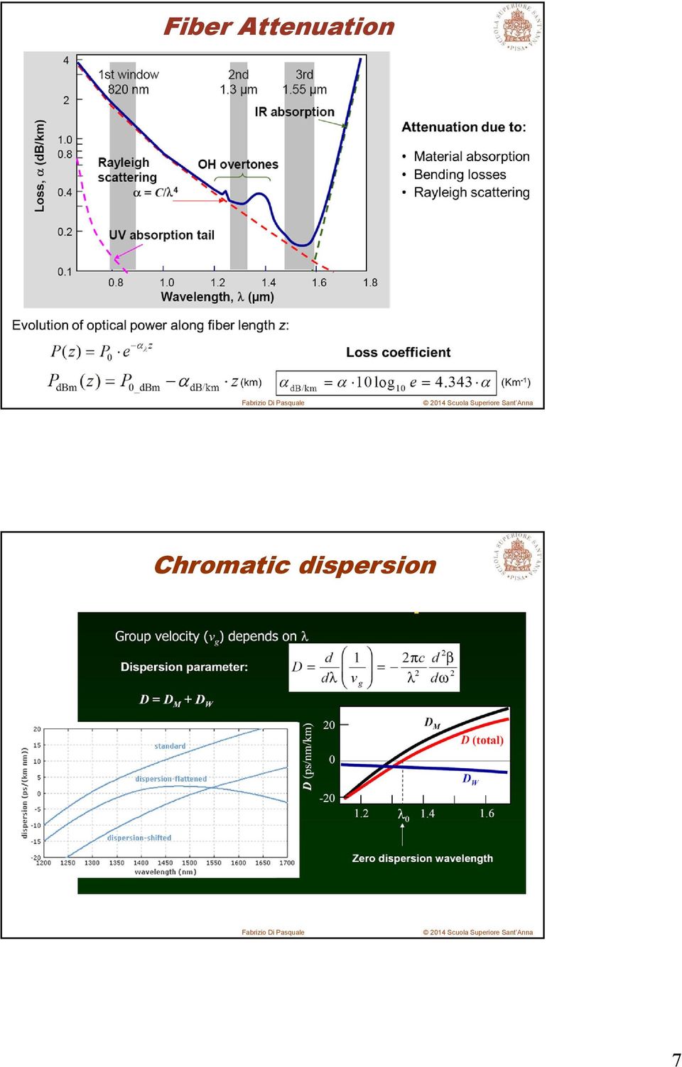
8 Fiber Attenuation Chromatic dispersion 7
9 Optical Fiber Sensors Basics Fiber-transmission and fiber-sensing systems Intensity, polarization, phase and frequency modulated sensors Individual-, multiplexed-, and distributed- sensors Principle of Photonic Sensing Intensity (Polarization) Measurand strain, speed, acceleration, rotation, pressure, acoustic wave, flow, temperature, electric field, magnetic field, electric current, gas, liquid, radiation, etc. E cos( 2 t ) Phase (Frequency) Transducing Effect Elastic-optic effect Thermal expansion Raman scattering Brillouin scattering Fluorescence etc. Optical Measurement Intensity Polarization Phase Frequency 8
 Phase (Frequency) Transducing Effect Elastic-optic effect Thermal expansion Raman scattering Brillouin scattering Fluorescence etc.")
10 Principle of Photonic Sensing Transmission Source Detector Voltage Current Magnetic field Temperature Acceleration, etc. Reflection Source Sensor Sound O 2 in Blood Micro wave power Temperature, etc. Detector Principle of Photonic Sensing Interferometer Source Detector Phase change Coupler Temperature Pressure Strain Magnetic field Sound, etc. Polarimeter Source Polarizer Polarization rotation Current Magnetic field, etc. Faraday effect Power Meter Source Loss change SoundMicro bending) Gas concentration Evanescent wave Radiation, etc. 9

11 Why Fiber Optic Sensors? Light properties in fiber are sensitive to environmental disturbance Optical fiber easily to be configured into host material or structure and not degrade the host Optical fibers are not sensitive to EMI Multiplexed OFS (WDM, TDM, SDM) Distributed sensing (long sensing distances) No electric power requirement at the sensing point High temperature values can be reached Multiplexed and Distributed Sensors Example of Multiplexed Sensor Source Detector Sensor Sensor Sensor Strain Temperature Pressure Sound, etc. Example of Distributed Sensor OTDR pulse Source Detector Scattering: Rayleigh Raman Brillouin Temperature Strain Lateral force Faults Water, oil, etc. 10

12 Approaches for Multiplexed Fiber Sensors Time Division Multiplex TDM) Wavelength Division Multiplex WDM) Broadband Source Optical A B C D E Filter Pulse Sensor A B C D E Sensor A B C D E Time Wavelengthdemultiplexer A B C D E Examples of Fiber Sensors FBG-based sensors Distributed backscattering-based sensors Raman scattering based distributed sensors Brillouin scattering based distributed sensors Rayleigh scattering based distributed sensors 11

13 Fiber Bragg Grating Sensors Periodic refractive index variations within the optical fiber core lead to light reflection at specific wavelength FBG couples the forward propagating core modes to backward modes at the wavelength B corresponding to resonance condition: (n is the effective index of the core mode and is the period) B 2n Typical structure of a uniform Fiber Bragg Grating FBG for strain & temperature sensing Physical Mechanisms Changes induced in the periodic refractive index variations of the FBG will lead to wavelength variations in the reflected light Temperature and strain variations induce changes in the refractive index periodicity of the FBG 0 Loss in db R e fle c tio n T ra n s m is s io n Strain & temperature cross-sensitivity W a v e le n g th in n m P e : strain optic coefficient : thermal expansion coefficient n : thermo-optic coefficient 12

14 Introduction to distributed optical fiber sensors Distributed fiber sensors allow the measurement of physical properties along fiber length (temperature, strain, etc.) based on optical reflectometry Optical Time Domain Reflectometry (OTDR) Optical Frequency Domain Reflectometry (OFDR) Coherent Optical Frequency Domain Reflectometry (C-OFDR) Optical Low Coherence Reflectometry (OLCR) Optical Time Domain Reflectometry OTDR Optical Frequncy Domain Reflectometry OFDR PD 13
 Coherent Optical Frequency Domain Reflectometry (C-OFDR) Optical Low Coherence Reflectometry (OLCR) Optical")
15 Optical time-domain reflectometry Laser Pulse width determines the spatial resolution (e.g. 10 ns 1 m sp. res.) Detector OTDR z To increase SNR at the receiver: Use higher peak power limited by nonlinear effects Use longer pulses degrades the spatial resolution Dynamic range limited by receiver sensitivity Low SNR at long distances Trade off between distance range and spatial resolution To overcome the limitations Use receiver with higher sensitivity (e.g. coherent detectors) Use of optical pulse coding Spreading signal in time domain More optical input power It avoids to use high peak power pulses (nonlinearities) It allows to improve the SNR with no impact on the spatial resolution Scattering phenomena used in DOFS Distributed optical fiber sensors based on optical-time domain reflectrometry (OTDR) Laser Detector OTDR Intensity ROTDR Raman scattering (Anti-stokes) Rayleigh scattering Laser frequency Brillouin scattering Raman scattering (stokes) BOTDR BOTDA 2-waves interaction Stimulated Brillouin scattering Temperature dependent wavelength Temperature and strain dependent 14

16 Spontaneous Raman Scattering and Phonons Raman scattering is generated by light interaction with resonant modes of the molecules in the medium (vibrational modes) Raman Stokes Raman Anti-Stokes Phonons interact with photons in inelastic scattering Stokes line photon energy is given to phonon Anti-Stokes line phonon gives energy to photon Spontaneous Raman Scattering and Phonons The high energy of vibrational modes induce a large Raman frequency shift ( 13 THz in silica fibers) For each molecular vibration two Raman components are observed: At different increasing temperature thermal excitation increases both Raman S and AS (asymmetry between Raman S and AS!) 15

17 Spontaneous Raman Scattering and Phonons Transition rates and propagation equations due to thermal excitation: Stokes Anti-Stokes N 0 is the incident photon flux (proportional to pump intensity) S and AS are the Raman Stokes and Anti-Stokes capture coefficients N is the Bose-Einstein thermal population factor: h: Plank constant K B : Boltzman constant R : vibration frequency T: absolute temperature W AS W S at high T W AS /W S 0 for T 0 K Raman based distributed temperature sensors pump BS AS S T dependence of phonon population T dependence of SRS light Ratio R(T) : P AS / P S (or P AS / P BS ) is usually used Raman temperature sensitivity: 0.8% K -1 16
 : P AS / P S (or P AS / P BS ) is usually used Raman temperature sensitivity: 0.")
18 Spontaneous Raman Scattering (Stokes) (anti-stokes) T Suitable for Temperature Sensing only 12.5 THz (100 nm) Advantages Easy detection High sensitivity Disadvantages Low backscattered power High input power required Sensitivity: 0.8 % /K Brillouin Scattering optical fiber acoustic wave optical fiber acoustic wave pump [ ] pump [ ] v a v a stokes [ - B ] probe [ - B ] Doppler shift Spontaneous Brillouin Scattering probe's gain Stimulated Brillouin Scattering Acoustic wave works as a diffraction grating Stokes wave s frequency is down-shifted by Doppler shift Probe s gain profile is called Brillouin gain spectrum (BGS) 17
![8 % /K Brillouin Scattering optical fiber acoustic wave optical fiber acoustic wave pump [ ] pump [ ] v a v a stokes [ - B ] probe [ - B ] Doppler shift](/docs-images/41/6369081/images/page_18.jpg "Spontaneous Brillouin Scattering probe's gain Stimulated Brillouin Scattering Acoustic wave works as a diffraction grating Stokes wave s frequency is")
19 Utilization of BGS for Sensors Brillouin Gain Spectrum (BGS) Brillouin Frequency Shift : v B ~ 11 GHz scanning Brillouin line width v B ~ 30 MHz freq. Brillouin frequency shift 2nVa B n: refractive index V a : acoustic wave velocity p : pump wavelength p probe pump Brillouin frequency shift and intensity change linearly against 1 tensile strain and temperature CP T 0.36 % C B C PB C B PB C BT C PB T T B 4 1 CP 910 % B 1 C 1.07 MHz C BT 1 C MHz B Stimulated Brillouin Scattering A pulsed pump and a CW signal are counter-propagating along a single mode optical fiber pump probe P probe (0) L P probe (L) The probe power at z = 0 is maximum when the frequency difference between pump and signal is equal to the Brillouin frequency shift f = B ( 10 GHz) B is a linear function of the temperature T and strain with the coefficients: C T 1.1 MHz/ C, C MHz/ T C B C T 18
 L P probe (L) The probe power at z = 0 is")
20 Stimulated Brillouin Scattering Generation of a pressure wave by electrostriction The two counter-propagating waves generate an acoustic wave through electrostriction effect The acoustic wave induces energy transfer from pump (lower wavelength) to signal (longer wavelength) Limitations in conventional time domain techniques Use of a pulsed lightwave Pulse width is set to be shorter than acoustic dumping time Gain spectrum obtained is flattened Spatial resolution in BOTDR is limited to ~ 1m Integration is required to obtain S/N ratio: only static sensing - Separating pump from Brillouin line: FBGs, coherent detection 19

21 Optical time-domain reflectometry Optical Time Domain Reflectometry Overview of OTDR Dynamic range, dead-zones and resolution OTDR signal analysis OTDR measurements Use in optical communication systems 20
22 Typical OTDR Scheme Pulse widths between 5 ns and 1 s (0.5 m to 100 m spatial resolutions) Circulator, 3 db coupler, optical filters for detecting backscattered light Pin or APD photoreceiver, 1310 nm or 1550 nm, 1620 nm wavelengths OTDR principles Analog-to-digital-converter (ADC) is the interface from analog to digital signals The ADC sampling rate determines the spatial resolution of adjacent data samples (50 MHz sampling rate corresponds to a data spacing of ~ 2 meter) It is not practical to increase the resolution by increasing the sampling rate Interleaved processing schemes are usually used to improve the spatial resolution High bandwidth is required in the signal processing to avoid smoothing of the final results As the backscattered signal is usually weak averaging is used to improve the SNR 21
23 ADC interleaved sampling For good shape resolution, pulses should be short ADC sampling rate should be high Common use of interleaved data acquisition (longer acquisition time necessary) Example of OTDR trace Time delay with respect to pulse launch is converted into distance: T 2L g Round trip propagation delay T: ~ 10 s/km 8 c 3 10 m / s 8 g 2 10 m / s n 1.5 One-way OTDR diagrams: 5log 10 (P) X-axis accuracy: exact timing, group index, cabling factor ~ 0.01% T acc 22
24 Main features of OTDR traces Distributed Rayleigh backscattering gives rise to straight lines in OTDR traces Non-reflective events give rise to positive or negative steps - fusion splices - bends Reflective events give rise to positive spikes - mechanical splices - connectors - cracks Fresnel reflection at fiber end connector is about 4% of incident light Time averaging SNR improved with time averaging Longer acquisition time Noise amplitude depends on number of acquired samples N as: 1/ N noise Not averaged noise N Averaged SNR improves with averaging samples proportionally with SNR specified typically after 3 min averaging time no avg 3 min avg N 23
25 Time averaging Time averaging =N 2 N 24
26 Example of time averaging A 20 km fiber link is tested with an OTDR at 1300 nm. Compute the noise reduction that can be achieved by signal averaging compared to a single shot measurement within the fist second and after 3 min, considering that 10% of the time is needed for processing overhead. s Round trip time for a 20 km fiber: T 10 20km 200s km Number of averages in 1 sec: N 1 1 s Number of averages in 3 min: N min The noise reduction is proportional to the square-root of N: SNR 1s SNR 10log( 3min 10log( N 1s N ) 5log(4500) 18.3dB 3min ) 5log(810000) 29.5dB Dynamic Range DYNAMIC RANGE: difference between initial backscatter level and noise level in one-way decibel Noise level specified typically after 3 mins of measurement time Measurement range dynamic range (measurement range deals with identification of events: 0.5 db splice is usually chosen as the event to be identified). It is the maximum attenuation that can be inserted between the OTDR and an event for which the OTDR is still able to measure the event. 25
27 Attenuation Deadzone Reflective events cause saturation of the receiver, with recovery time inversely proportional to the receiver bandwidth ATTENUATION DEADZONE: distance from start of a reflective event and recovery within 0.5 db of backscatter trace Spatial resolution typically defined as one-way distance from 10% to 90% power increase for a reflective event RISE TIME RESPONSE TIME Trade-off between dynamic range and resolution: s( t) p( t) f ( t) r( t) EXAMPLE Dynamic Range and Resolution Spatial resolution: ability to detect two different events with a given distance spacing Received signal as convolution of the probing pulse p(t), backscattering impulse response of the fiber f(t) and impulse response of the receiver r(t) Longer pulses higher dynamic range less spatial resolution 26
28 Fiber attenuation and Scattering Attenuation due to: Material absorption (intrinsic+extrinsic) Bending losses Rayleigh scattering R M MB mb Evolution of optical power along fiber length z: Pz ( ) Pe z 0 P ( z) P z In db: dbm 0_dBm db/km Loss coefficient 10log e db/km 10 Rayleigh Scattering Rayleigh scattering: Microscopic variations of refractive index n with a spatial scale << than signal cause scattering of lightwave signal in all directions power loss Rayleigh scattering absorption coefficient in Silica fibers: s c 4 C: constant 3 rd window: s = R ~ 0.1 db/km, absorption is dominated by Rayleigh scattering Signal backscattering: A fraction of scattered signal is collected by fiber NA in backward propagating direction Rayleigh back-scattering coefficient : S R m4.5 for SMF, S10-3 S: capture factor (fiber geometry, NA) ~ /km 27
29 Measuring Distance with Light Pulses (OTDR) Spatial Resolution Optical Time-Domain Reflectometry L t L ct /( 2n) Spatial resolution is basically determined by the pulse-width. In glass (fiber): 10 ns 1 m 1 ns 10 cm 1 ps 0.1 mm c = m/s Analysis of OTDR traces W v g Group velocity Pulse duration =S s s : backscattering coeff. 1/ 4 S: capture factor Scattered power at position z with infinitesimal length interval dz: dps( z) P( z) dz 28
30 Analysis of OTDR traces Integrating on pulse spatial width W we obtain total received power at time T, corresponding to the distance L : W v g For short pulses W << 1 (W<<1/ ) we can simplify the expression at fiber distance L: P ( L) S W P e s s 0 2L S P e s g 0 2L For short pulses the backscattered power is proportional to the pulse duration Backscatter factor : db) 10 log( S W ) 10 log( S ) ( s s g [db/s] Analysis of OTDR traces Backscattered power proportional to pulse duration P ( L) S W P e s s 0 2L W vg BACKSCATTER FACTOR is typically specified for optical fibers: TYPICAL VALUES 29
31 Analysis of OTDR traces Example: 100 km fiber is probed with an OTDR having a peak output power of 13 dbm and the pulsewidth is 10 sec. Calculate the backscattered power returning from the far end of the fiber having attenuation of 0.33 db/km, a scattering coeff. of 0.3 db/km and capture factor S=10-3 at 1300 nm. P ( L) S W P e s s 0 2L W vg 2km Measurement of splice and connector losses OTDR can be used to measure loss from splices, bending and connectors Different Rayleigh backscattering coefficients before and after an event can affect the inserction loss measurement accuracy L2 L1 Least-square-approximation is usually used to determine the slopes and positions of the two lines L1 and L2 30
32 Splice Loss Measurement Least mean square approx of attenuations Backscatter coefficients should be the same for the two fibers Splice Loss Measurement If BS coefficients are not the same, then gain can be seen by OTDR 31
33 Insertion Loss Measurement Air gap of a tiny crack, a mechanical splice, a connector are examples of reflective events. Also misalignement of connectors, mismatch in core dimensions or NA can induce additional losses Inserction loss Position of reflection Extrapolation of reflection point for IL measurement in a reflective event 32
Module 13 : Measurements on Fiber Optic Systems
 Module 13 : Measurements on Fiber Optic Systems Lecture : Measurements on Fiber Optic Systems Objectives In this lecture you will learn the following Measurements on Fiber Optic Systems Attenuation (Loss)
PIPELINE LEAKAGE DETECTION USING FIBER-OPTIC DISTRIBUTED STRAIN AND TEMPERATURE SENSORS WHITE PAPER
 PIPELINE LEAKAGE DETECTION USING FIBER-OPTIC DISTRIBUTED STRAIN AND TEMPERATURE SENSORS WHITE PAPER Lufan Zou and Taha Landolsi OZ Optics Limited, 219 Westbrook Road, Ottawa, ON, Canada, K0A 1L0 E-mail:
Limiting factors in fiber optic transmissions
 Limiting factors in fiber optic transmissions Sergiusz Patela, Dr Sc Room I/48, Th. 13:00-16:20, Fri. 9:20-10:50 sergiusz.patela@pwr.wroc.pl eportal.pwr.wroc.pl Copying and processing permitted for noncommercial
BOTDR Measurement Techniques and Brillouin Backscatter Characteristics of Corning Single-Mode Optical Fibers
 BOTDR Measurement Techniques and Brillouin Backscatter Characteristics of Corning Single-Mode Optical Fibers WP4259 Issued: January 2015 Brillouin Optical Time Domain Reflectometry The Brillouin Optical
Explanation of Reflection Features in Optical Fiber as Sometimes Observed in OTDR Measurement Traces
 Explanation of Reflection Features in Optical Fiber as Sometimes Observed in OTDR Measurement Traces WP1281 Issued: November 2015 Supersedes: 2012 Author: Dr. Russell Ellis ISO 9001 Registered Background
MTS/T-BERD Platforms Very Long Range (VLR) OTDR Module
 OTDR Module") COMMUNICATIONS TEST & MEASUREMENT SOLUTIONS MTS/T-BERD Platforms (VLR) OTDR Module Key Features CWDM/DWDM ready with 1310, 1383, 1490, 1550, and 1625 nm wavelengths FTTx ready with 1310/1490/1550 nm wavelengths
COMMUNICATIONS TEST & MEASUREMENT SOLUTIONS MTS/T-BERD Platforms (VLR) OTDR Module Key Features CWDM/DWDM ready with 1310, 1383, 1490, 1550, and 1625 nm wavelengths FTTx ready with 1310/1490/1550 nm wavelengths
Optical fibre sensors for hydro-geological applications
 Optical fibre sensors for hydro-geological applications L. Schenato National Research Council, Research Institute for Hydro-Geological Protection - Padova Unit - Italy 2 Spoiler alert! Giving away the
Christine E. Hatch University of Nevada, Reno
 Christine E. Hatch University of Nevada, Reno Roadmap What is DTS? How Does it Work? What Can DTS Measure? Applications What is Distributed Temperature Sensing (DTS)? Temperature measurement using only
Fibre Bragg Grating Sensors An Introduction to Bragg gratings and interrogation techniques
 Fibre Bragg Grating Sensors An ntroduction to Bragg gratings and interrogation techniques Dr Crispin Doyle Senior Applications Engineer, Smart Fibres Ltd. 2003 1) The Fibre Bragg Grating (FBG) There are
Removing the Mystery from OTDR Measurements. Keith Foord Product Manager Greenlee Communications
 Removing the Mystery from OTDR Measurements Keith Foord Product Manager Greenlee Communications Why an OTDR? Terminology Theory Standards Key specifications Trade-offs Cleaning and Inspection Measurements
Fiber Optic Specifications
 Fiber Optic Specifications All Fiber Optic shall be Corning Altos Single Mode OS1 Outdoor Loose Tube Gel Free Cable Corning Fiber Products only will be accepted and no substitutions or alternates will
École Supérieure d'optique
 Conference on Education and Training in Optics & Photonics Marseille, 27 th October 2005 An Optical Time Domain Reflectometry Set-Up for Laboratory Work at École Supérieure d'optique École Supérieure d'optique
What are Fibre Optics?
 Fibre Optics Fibre Optics? Fibre optics (optical fibres) are the guiding channels through which light energy propagates. These are long, thin strands of very pure glass about the diameter of a human hair
Measuring of optical output and attenuation
 Measuring of optical output and attenuation THEORY Measuring of optical output is the fundamental part of measuring in optoelectronics. The importance of an optical power meter can be compared to an ammeter
Fiber optic communication
 Fiber optic communication Fiber optic communication Outline Introduction Properties of single- and multi-mode fiber Optical fiber manufacture Optical network concepts Robert R. McLeod, University of Colorado
Fiber Optics: Fiber Basics
 Photonics Technical Note # 21 Fiber Optics Fiber Optics: Fiber Basics Optical fibers are circular dielectric wave-guides that can transport optical energy and information. They have a central core surrounded
Introduction to Optical Link Design
 University of Cyprus Πανεπιστήµιο Κύπρου 1 Introduction to Optical Link Design Stavros Iezekiel Department of Electrical and Computer Engineering University of Cyprus HMY 445 Lecture 08 Fall Semester 2014
Data Transmission. Data Communications Model. CSE 3461 / 5461: Computer Networking & Internet Technologies. Presentation B
 CSE 3461 / 5461: Computer Networking & Internet Technologies Data Transmission Presentation B Kannan Srinivasan 08/30/2012 Data Communications Model Figure 1.2 Studying Assignment: 3.1-3.4, 4.1 Presentation
T = 1 f. Phase. Measure of relative position in time within a single period of a signal For a periodic signal f(t), phase is fractional part t p
, phase is fractional part t p") Data Transmission Concepts and terminology Transmission terminology Transmission from transmitter to receiver goes over some transmission medium using electromagnetic waves Guided media. Waves are guided
Data Transmission Concepts and terminology Transmission terminology Transmission from transmitter to receiver goes over some transmission medium using electromagnetic waves Guided media. Waves are guided
FIBER LASER STRAIN SENSOR DEVICE
 FIBER LASER STRAIN SENSOR DEVICE E. Maccioni (1,2), N. Beverini (1,2), M. Morganti (1,2) F. Stefani (2,3), R. Falciai (4), C. Trono (4) (1) Dipartimento di Fisica E. Fermi Pisa (2) INFN Sez. Pisa (3) Dipartimento
Attaching the PA-A1-ATM Interface Cables
 CHAPTER 4 Attaching the PA-A1-ATM Interface Cables To continue your PA-A1-ATM port adapter installation, you must attach the port adapter cables. The instructions that follow apply to all supported platforms.
Optical Fibers Fiber Optic Cables Indoor/Outdoor
 presents Optical Fibers Fiber Optic Cables Indoor/Outdoor Content Optical fiber function, types optical effects applications production of optical fibre Cable - general types Indoor Indoor / outdoor Outdoor
Optical Fiber Data Center Field Testing. ANSI/BICSI 002-2011 Data Center Design and Implementation Best Practices
 Optical Fiber Data Center Field Testing ANSI/BICSI 002-2011 Data Center Design and Implementation Best Practices Abstract Data Centers are a growing segment of the enterprise market. Regardless of whether
Cabling & Test Considerations for 10 Gigabit Ethernet LAN
 Introduction Current communication data rates in local networks range from 10/100 megabits per second (Mbps) in Ethernet to 1 gigabit per second (Gbps) in fiber distributed data interface (FDDI) and Gigabit
Antennas & Propagation. CS 6710 Spring 2010 Rajmohan Rajaraman
 Antennas & Propagation CS 6710 Spring 2010 Rajmohan Rajaraman Introduction An antenna is an electrical conductor or system of conductors o Transmission - radiates electromagnetic energy into space o Reception
USE OF FIBRE OPTICS INTERNATIONAL STANDARDS FOR CALIBRATION LABORATORY ACCREDITATION INTERNATIONAL ELECTROTECHNICAL COMMISSION
 USE OF FIBRE OPTICS INTERNATIONAL STANDARDS FOR CALIBRATION LABORATORY ACCREDITATION INTERNATIONAL ELECTROTECHNICAL COMMISSION USE OF FIBRE OPTICS INTERNATIONAL STANDARDS FOR CALIBRATION LABORATORY ACCREDITATION
DIRECTIONAL FIBER OPTIC POWER MONITORS (TAPS/PHOTODIODES)
") Features: DIRECTIONAL FIBER OPTIC POWER MONITORS (TAPS/PHOTODIODES) PATENT NUMBERS: CANADA 2,494,133, USA 7095931, 7295731 AND CHINA 1672073 Telcordia GR-468 qualified Available in versions for any wavelength
Features: DIRECTIONAL FIBER OPTIC POWER MONITORS (TAPS/PHOTODIODES) PATENT NUMBERS: CANADA 2,494,133, USA 7095931, 7295731 AND CHINA 1672073 Telcordia GR-468 qualified Available in versions for any wavelength
Fiber Optic Distributed Temperature Sensor (B-DTS)
") Fiber Optic Distributed Temperature Sensor (B-DTS) Low-cost Brillouin BOTDA scattering version For more information about our strain and temperature sensor system and related products, please visit www.ozoptics.com
Fiber Optic Distributed Temperature Sensor (B-DTS) Low-cost Brillouin BOTDA scattering version For more information about our strain and temperature sensor system and related products, please visit www.ozoptics.com
Wavelength Division Multiplexing
 WDM Wavelength Division Multiplexing -CWDM vs DWDM- Fargo, ND 1 Agenda 1. Overview 2. Fiber Cable WDM Characteristics 3. CWDM Course WDM 4. DWDM Dense WDM 5. Applications Best Fit- Future? 6. Summary Fargo,
Optical Fibres. Introduction. Safety precautions. For your safety. For the safety of the apparatus
 Please do not remove this manual from from the lab. It is available at www.cm.ph.bham.ac.uk/y2lab Optics Introduction Optical fibres are widely used for transmitting data at high speeds. In this experiment,
EE4367 Telecom. Switching & Transmission. Prof. Murat Torlak
 FIBER OPTIC COMMUNICATIONS Optical Fibers Fiber optics (optical fibers) are long, thin strands of very pure glass about the size of a human hair. They are arranged in bundles called optical cables and
Modulation Formats for High-Speed, Long-Haul Fiber Optic Communication Systems
 Modulation Formats for High-Speed, Long-Haul Fiber Optic Communication Systems Anjali Singh, Ph.D. Inphi Corporation, 2393 Townsgate Rd #101, Westlake Village, CA 91361 1. Introduction The goal of an optical
Acousto-optic modulator
 1 of 3 Acousto-optic modulator F An acousto-optic modulator (AOM), also called a Bragg cell, uses the acousto-optic effect to diffract and shift the frequency of light using sound waves (usually at radio-frequency).
The Conversion Technology Experts. Fiber Optics Basics
 The Conversion Technology Experts Fiber Optics Basics Introduction Fiber optic technology is simply the use of light to transmit data. The general use of fiber optics did not begin until the 1970s. Robert
Simulation and Best Design of an Optical Single Channel in Optical Communication Network
 International Arab Journal of e-technology, Vol., No., June 11 91 Simulation and Best Design of an Optical Single Channel in Optical Communication Network Salah Alabady Computer Engineering Department,
Distributed Intrusion Monitoring System With Fiber Link Backup and On-Line Fault Diagnosis Functions
 PHOTONIC SENSORS / Vol. 4, No. 4, 14: 354 358 Distributed Intrusion Monitoring System With Fiber Link Backup and On-Line Fault Diagnosis Functions Jiwei XU, Huijuan WU *, and Shunkun XIAO Key Laboratory
Optical Communications
 Optical Communications Telecommunication Engineering School of Engineering University of Rome La Sapienza Rome, Italy 2005-2006 Lecture #2, May 2 2006 The Optical Communication System BLOCK DIAGRAM OF
CABLE ASSET MANAGEMENT PREDICT WITH CERTAINTY. Kuljit Singh BSc Honours MIEE(IET,UK) 5 June 2014
 5 June 2014") CABLE ASSET MANAGEMENT PREDICT WITH CERTAINTY Kuljit Singh BSc Honours MIEE(IET,UK) 5 June 2014 Definitions International Workshop 2014 DTS: Distributed Temperature Sensor DCR: Dynamic Cable Ratings (
CABLE ASSET MANAGEMENT PREDICT WITH CERTAINTY Kuljit Singh BSc Honours MIEE(IET,UK) 5 June 2014 Definitions International Workshop 2014 DTS: Distributed Temperature Sensor DCR: Dynamic Cable Ratings (
Simulation of Gaussian Pulses Propagation Through Single Mode Optical Fiber Using MATLAB . MATLAB
 Iraqi Journal of Science, 213, Vol.4, No.3, pp.61-66 Simulation of Gaussian Pulses Propagation Through Single Mode Optical Fiber Using MATLAB Salah Al Deen Adnan Taha *, Mehdi M. Shellal, and Ahmed Chyad
Dispersion in Optical Fibers
 Dispersion in Optical Fibers By Gildas Chauvel Anritsu Corporation TABLE OF CONTENTS Introduction Chromatic Dispersion (CD): Definition and Origin; Limit and Compensation; and Measurement Methods Polarization
AMPLIFIED HIGH SPEED FIBER PHOTODETECTOR USER S GUIDE
 AMPLIFIED HIGH SPEED FIBER PHOTODETECTOR USER S GUIDE Thank you for purchasing your Amplified High Speed Fiber Photodetector. This user s guide will help answer any questions you may have regarding the
Plastic Optical Fiber for In-Home communication systems
 Plastic Optical Fiber for In-Home communication systems Davide Visani 29 October 2010 Bologna E-mail: davide.visani3@unibo.it Summary Reason for Fiber in the Home (FITH) FITH scenario Comparison of CAT5
Lecture 3: Fibre Optics
 Lecture 3: Fibre Optics Lecture aims to explain: 1. Fibre applications in telecommunications 2. Principle of operation 3. Single- and multi-mode fibres 4. Light losses in fibres Fibre is a transparent
GLOBAL COLLEGE OF ENGINEERING &TECHNOLOGY: YSR DIST. Unit VII Fiber Optics Engineering Physics
 Introduction Fiber optics deals with the light propagation through thin glass fibers. Fiber optics plays an important role in the field of communication to transmit voice, television and digital data signals
A Guide to Acousto-Optic Modulators
 A Guide to Acousto-Optic Modulators D. J. McCarron December 7, 2007 1 Introduction Acousto-optic modulators (AOMs) are useful devices which allow the frequency, intensity and direction of a laser beam
Impedance 50 (75 connectors via adapters)
") VECTOR NETWORK ANALYZER PLANAR TR1300/1 DATA SHEET Frequency range: 300 khz to 1.3 GHz Measured parameters: S11, S21 Dynamic range of transmission measurement magnitude: 130 db Measurement time per point:
VECTOR NETWORK ANALYZER PLANAR TR1300/1 DATA SHEET Frequency range: 300 khz to 1.3 GHz Measured parameters: S11, S21 Dynamic range of transmission measurement magnitude: 130 db Measurement time per point:
EECC694 - Shaaban. Transmission Channel
 The Physical Layer: Data Transmission Basics Encode data as energy at the data (information) source and transmit the encoded energy using transmitter hardware: Possible Energy Forms: Electrical, light,
Field Measurements of Deployed Fiber
 Field Measurements of Deployed Fiber Robert J. Feuerstein Level 3 Communications, 1025 Eldorado Boulevard, Broomfield, Colorado 80021 Robert.Feuerstein@Level3.com Abstract: New generations of ultra-long
Optical Amplifiers. Ericsson
 Optical Amplifiers Ericsson Introduction In any link, optical power pumped and the receiver sensitivity is limited and can only support for a limited distance To over come the losses in the network, either
Bandwidth analysis of multimode fiber passive optical networks (PONs)
") Optica Applicata, Vol. XXXIX, No. 2, 2009 Bandwidth analysis of multimode fiber passive optical networks (PONs) GRZEGORZ STEPNIAK *, LUKASZ MAKSYMIUK, JERZY SIUZDAK Institute of Telecommunications, Warsaw
Optica Applicata, Vol. XXXIX, No. 2, 2009 Bandwidth analysis of multimode fiber passive optical networks (PONs) GRZEGORZ STEPNIAK *, LUKASZ MAKSYMIUK, JERZY SIUZDAK Institute of Telecommunications, Warsaw
Subsea Asset Monitoring using Distributed Fiber Optic Sensing
 Subsea Asset Monitoring using Distributed Fiber Optic Sensing Carlos Borda Omnisens S.A. Subsea Asia Conference June 2014 Agenda Who is Omnisens? Distributed Fiber Optic Monitoring Power Umbilicals Flow
Fundamentals of Optical Communications
 University of Applied Science Departement of Electrical Eng. and Computer Science Fundamentals of Optical Communications Referent: Prof. Dr.-Eng. habilitas Steffen Lochmann S.Lochmann@gmx.net www.prof-lochmannde
Agilent E6020B FTTx OTDR
 Agilent E6020B FTTx OTDR Fast and Cost-effective Fiber Installation for Access Networks Technical Data Sheet Introducing the New FTTx OTDR Agilent's new E6020B FTTx OTDR is a cost-effective, easy to use
E190Q Lecture 5 Autonomous Robot Navigation
 E190Q Lecture 5 Autonomous Robot Navigation Instructor: Chris Clark Semester: Spring 2014 1 Figures courtesy of Siegwart & Nourbakhsh Control Structures Planning Based Control Prior Knowledge Operator
Raman spectroscopy Lecture
 Raman spectroscopy Lecture Licentiate course in measurement science and technology Spring 2008 10.04.2008 Antti Kivioja Contents - Introduction - What is Raman spectroscopy? - The theory of Raman spectroscopy
An advanced Dark Fiber Monitoring System for Next Generation Optical Access Networks
 An advanced Dark Fiber Monitoring System for Next Generation Optical Access Networks Min Cen, Jiajia Chen, Véronique Moeyaert, Patrice Mégret and Marc Wuilpart 18th Annual Workshop of the IEEE Photonics
Technical Datasheet Scalar Network Analyzer Model 8003-10 MHz to 40 GHz
 Technical Datasheet Scalar Network Analyzer Model 8003-10 MHz to 40 GHz The Giga-tronics Model 8003 Precision Scalar Network Analyzer combines a 90 db wide dynamic range with the accuracy and linearity
Different Types of Dispersions in an Optical Fiber
 International Journal of Scientific and Research Publications, Volume 2, Issue 12, December 2012 1 Different Types of Dispersions in an Optical Fiber N.Ravi Teja, M.Aneesh Babu, T.R.S.Prasad, T.Ravi B.tech
Near-field scanning optical microscopy (SNOM)
") Adviser: dr. Maja Remškar Institut Jožef Stefan January 2010 1 2 3 4 5 6 Fluorescence Raman and surface enhanced Raman 7 Conventional optical microscopy-limited resolution Two broad classes of techniques
Adviser: dr. Maja Remškar Institut Jožef Stefan January 2010 1 2 3 4 5 6 Fluorescence Raman and surface enhanced Raman 7 Conventional optical microscopy-limited resolution Two broad classes of techniques
OFS AllWave Zero Water Peak (ZWP) single-mode
 single-mode") The New Standard for Single-Mode Fiber Product Description OFS AllWave Zero Water Peak (ZWP) single-mode optical fiber is the industry s first full-spectrum fiber designed for optical transmission systems
The New Standard for Single-Mode Fiber Product Description OFS AllWave Zero Water Peak (ZWP) single-mode optical fiber is the industry s first full-spectrum fiber designed for optical transmission systems
A continuously tunable multi-tap complexcoefficient microwave photonic filter based on a tilted fiber Bragg grating
 A continuously tunable multi-tap complexcoefficient microwave photonic filter based on a tilted fiber Bragg grating Hiva Shahoei and Jianping Yao * Microwave Photonics Research Laboratory, School of Electrical
Application Note Noise Frequently Asked Questions
 : What is? is a random signal inherent in all physical components. It directly limits the detection and processing of all information. The common form of noise is white Gaussian due to the many random
EE4367 Telecom. Switching & Transmission. Prof. Murat Torlak
 Path Loss Radio Wave Propagation The wireless radio channel puts fundamental limitations to the performance of wireless communications systems Radio channels are extremely random, and are not easily analyzed
Chapter 2 OPTICAL FIBER CHARACTERISTICS AND SYSTEM CONFIGURATIONS
 Chapter OPTICAL FIBER CHARACTERISTICS AND SYSTEM CONFIGURATIONS One attractive aspect of optical fibers is their enormous bandwidth compared to other media, such as radio waves and twisted-pair wires.
BIOMEDICAL ULTRASOUND
 BIOMEDICAL ULTRASOUND Goals: To become familiar with: Ultrasound wave Wave propagation and Scattering Mechanisms of Tissue Damage Biomedical Ultrasound Transducers Biomedical Ultrasound Imaging Ultrasonic
Pump-probe experiments with ultra-short temporal resolution
 Pump-probe experiments with ultra-short temporal resolution PhD candidate: Ferrante Carino Advisor:Tullio Scopigno Università di Roma ƒla Sapienza 22 February 2012 1 Pump-probe experiments: generalities
Interferometric Measurement of Dispersion in Optical Components
 Interferometric Measurement of Dispersion in Optical Components Mark Froggatt, Eric Moore, and Matthew Wolfe Luna Technologies, Incorporated, 293-A Commerce Street, Blacksburg, Virginia 246 froggattm@lunatechnologies.com.
OFDR-Based Distributed Sensing and Fault Detection for Single- and Multi-Mode Avionics Fiber-Optics
 OFDR-Based Distributed Sensing and Fault Detection for Single- and Multi-Mode Avionics Fiber-Optics Roger G. Duncan, Brian J. Soller, Dawn K. Gifford, Steven T. Kreger, Ryan J. Seeley, Alexander K. Sang,
INTRODUCTION FIGURE 1 1. Cosmic Rays. Gamma Rays. X-Rays. Ultraviolet Violet Blue Green Yellow Orange Red Infrared. Ultraviolet.
 INTRODUCTION Fibre optics behave quite different to metal cables. The concept of information transmission is the same though. We need to take a "carrier" signal, identify a signal parameter we can modulate,
Designing Fiber Optic Systems David Strachan
 Designing Fiber Optic Systems David Strachan Everyone knows that fiber optics can carry a huge amount of data. There are more benefits to using fiber optics in broadcast applications than you might realize.
Laser-induced surface phonons and their excitation of nanostructures
 CHINESE JOURNAL OF PHYSICS VOL. 49, NO. 1 FEBRUARY 2011 Laser-induced surface phonons and their excitation of nanostructures Markus Schmotz, 1, Dominik Gollmer, 1 Florian Habel, 1 Stephen Riedel, 1 and
OPTICAL FIBERS INTRODUCTION
 OPTICAL FIBERS References: J. Hecht: Understanding Fiber Optics, Ch. 1-3, Prentice Hall N.J. 1999 D. R. Goff: Fiber Optic Reference Guide (2 nd ed.) Focal Press 1999 Projects in Fiber Optics (Applications
Propagation Channel Emulator ECP_V3
 Navigation simulators Propagation Channel Emulator ECP_V3 1 Product Description The ECP (Propagation Channel Emulator V3) synthesizes the principal phenomena of propagation occurring on RF signal links
Robot Perception Continued
 Robot Perception Continued 1 Visual Perception Visual Odometry Reconstruction Recognition CS 685 11 Range Sensing strategies Active range sensors Ultrasound Laser range sensor Slides adopted from Siegwart
The following terms are defined within the context of the fiber optic industry
 The following terms are defined within the context of the fiber optic industry Adapter A mechanical media termination device designed to align and join fiber optic connectors. Often referred to as coupling,
Fundamentals of modern UV-visible spectroscopy. Presentation Materials
 Fundamentals of modern UV-visible spectroscopy Presentation Materials The Electromagnetic Spectrum E = hν ν = c / λ 1 Electronic Transitions in Formaldehyde 2 Electronic Transitions and Spectra of Atoms
FIA Breakfast Seminar June 2000 TESTING SOLUTIONS FOR NEW FIBRE OPTICS. prepared and delivered by. FIA Breakfast Seminar 21st June 2000 9.15-10.
 Breakfast prepared and delivered by Breakfast Seminar 21st June 2000 9.15-10.30 Optical Test and Calibration 5 Campus Road Listerhills Science Park Bradford BD7 1HR Tel: +44 (0) 1274 393857 Fax: +44 (0)
FIBER OPTIC COMMUNICATIONS. Optical Fibers
 FIBER OPTIC COMMUNICATIONS Optical Fibers Fiber optics (optical fibers) are long, thin strands of very pure glass about the size of a human hair. They are arranged in bundles called optical cables and
Graphical User Interface Capabilities of MATLAB in Centralized Failure Detection System (CFDS)
") INTERNATIONAL JOURNAL OF MICROWAVE AND OPTICAL TECHNOLOGY 128 Graphical User Interface Capabilities of MATLAB in Centralized Failure Detection System (CFDS) Mohammad Syuhaimi Ab-Rahman* and Boonchuan Ng
INTERNATIONAL JOURNAL OF MICROWAVE AND OPTICAL TECHNOLOGY 128 Graphical User Interface Capabilities of MATLAB in Centralized Failure Detection System (CFDS) Mohammad Syuhaimi Ab-Rahman* and Boonchuan Ng
Raman Spectroscopy. 1. Introduction. 2. More on Raman Scattering. " scattered. " incident
 February 15, 2006 Advanced Physics Laboratory Raman Spectroscopy 1. Introduction When light is scattered from a molecule or crystal, most photons are elastically scattered. The scattered photons have the
Radio over Fiber technologies for in-building networks
 Radio over Fiber technologies for in-building networks Davide Visani 29 October 2010 Bologna E-mail: davide.visani3@unibo.it Summary Reason for a Distributed Antenna Systems (DAS) Radio over Fiber technologies
Waves - Transverse and Longitudinal Waves
 Waves - Transverse and Longitudinal Waves wave may be defined as a periodic disturbance in a medium that carries energy from one point to another. ll waves require a source and a medium of propagation.
APPLICATION NOTE POLARIZATION MEASUREMENTS
 OZ OPTICS LTD. APPLICATION NOTE POLARIZATION MEASUREMENTS OZ OPTICS FAMILY OF POLARIZATION MAINTAINING COMPONENTS, SOURCES, AND MEASUREMENT SYSTEMS The information/data furnished in this document shall
FIBER OPTIC SYSTEM TEST PROCEDURES
 FIBER OPTIC SYSTEM TEST PROCEDURES Data Systems Performance Engineering LLC performs three tests in order to determine fiber optic cable adequacy. The order in which the tests are to be performed is not
MINIMIZING PMD IN CABLED FIBERS. Critical for Current and Future Network Applications
 MINIMIZING PMD IN CABLED FIBERS Critical for Current and Future Network Applications David Mazzarese Technical Marketing Manager OFS Sturbridge, Mass. Polarization Mode Dispersion (PMD) is a serious problem
Insertion Losses of Fiber Optical Connectors
 Insertion Losses of Fiber Optical Connectors Martin Strasser, Fiber Optics, HUBER+SUHNER AG, Switzerland H+S Technical Series HUBER+SUHNER Excellence in Connectivity Solutions Table of contents 1 Origins
Incoherent beam combining using stimulated Brillouin scattering in multimode fibers
 Incoherent beam combining using stimulated Brillouin scattering in multimode fibers Timothy H. Russell and Won B. Roh Air Force Institute of Technology, Wright-Patterson AFB, Ohio 45433 timothy.russell@afit.edu;
USER MANUAL FIBER OPTIC ANALOG TRANSMITTER AND RECEIVER MODULE
 USER MANUAL FIBER OPTIC ANALOG TRANSMITTER AND RECEIVER MODULE Table of Contents 1. INTRODUCTION... 3 2. PREFACE... 4 2.1 Transmitter... 4 2.2 Optical fiber... 4 2.3 Receiver... 5 2.4 Advantage of Optical
Data Sheet. HFBR-0600Z Series SERCOS Fiber Optic Transmitters and Receivers
 HFBR-0600Z Series SERCOS Fiber Optic Transmitters and Receivers Data Sheet SERCOS SERCOS is a SErial Realtime COmmunication System, a standard digital interface for communication between controls and drives
CABLE MONITORING SOLUTION
 POWER CABLE MONITORING SOLUTION Kuljit Singh BSc Honours MIEE(IET,UK) Dan Watley Ph. D, B.A MEng (UK), MIEEE, UK 8-9 November 2011 PREDICT WITH CERTAINTY Definition DTS: Distributed Temperature Sensor
AS COMPETITION PAPER 2008
 AS COMPETITION PAPER 28 Name School Town & County Total Mark/5 Time Allowed: One hour Attempt as many questions as you can. Write your answers on this question paper. Marks allocated for each question
Network Analyzer Operation
 Network Analyzer Operation 2004 ITTC Summer Lecture Series John Paden Purposes of a Network Analyzer Network analyzers are not about computer networks! Purposes of a Network Analyzer Measures S-parameters
Experiment 5. Lasers and laser mode structure
 Northeastern University, PHYS5318 Spring 2014, 1 1. Introduction Experiment 5. Lasers and laser mode structure The laser is a very important optical tool that has found widespread use in science and industry,
INTRODUCTION TO COMMUNICATION SYSTEMS AND TRANSMISSION MEDIA
 COMM.ENG INTRODUCTION TO COMMUNICATION SYSTEMS AND TRANSMISSION MEDIA 9/6/2014 LECTURES 1 Objectives To give a background on Communication system components and channels (media) A distinction between analogue
Raman Spectroscopy Basics
 Raman Spectroscopy Basics Introduction Raman spectroscopy is a spectroscopic technique based on inelastic scattering of monochromatic light, usually from a laser source. Inelastic scattering means that
Challenges in DWDM System Spectral Analysis By Laurent Begin and Jim Nerschook
 Challenges in DWDM System Spectral Analysis By Laurent Begin and Jim Nerschook TABLE OF CONTENTS: 1.0 Satisfying the Thirst for Bandwidth 02 2.0 The Solution, DWDM 02 3.0 Resolution 04 4.0 Wavelength Accuracy
Vector Network Analyzer Techniques to Measure WR340 Waveguide Windows
 LS-296 Vector Network Analyzer Techniques to Measure WR340 Waveguide Windows T. L. Smith ASD / RF Group Advanced Photon Source Argonne National Laboratory June 26, 2002 Table of Contents 1) Introduction
Large-Capacity Optical Transmission Technologies Supporting the Optical Submarine Cable System
 Large-Capacity Optical Transmission Technologies Supporting the Optical Submarine Cable System INOUE Takanori Abstract As one of the foundations of the global network, the submarine cable system is required
A wave lab inside a coaxial cable
 INSTITUTE OF PHYSICS PUBLISHING Eur. J. Phys. 25 (2004) 581 591 EUROPEAN JOURNAL OF PHYSICS PII: S0143-0807(04)76273-X A wave lab inside a coaxial cable JoãoMSerra,MiguelCBrito,JMaiaAlves and A M Vallera
Advancements in High Frequency, High Resolution Acoustic Micro Imaging for Thin Silicon Applications
 Advancements in High Frequency, High Resolution Acoustic Micro Imaging for Thin Silicon Applications Janet E. Semmens Sonoscan, Inc. 2149 E. Pratt Boulevard Elk Grove Village, IL 60007 USA Phone: (847)