CAPLAN a comprehensive view
|
|
|
- Isabel Gibson
- 8 years ago
- Views:
Transcription
1 cremer programmentwicklung gmbh CAPLAN a comprehensive view CAPLAN

2 CAPLAN Contents CAPLAN for Surveying and Civil Engineering Project Database Plan Window Engineering Surveying I Engineering Surveying II Processing of Polar Observations Leveling GNSS / Transformations Deformation Analysis CC and CREDIT Picture credits: Fotolia.com: p.2 antiksu; p.3 Peter Atkins; p.4+p.6+p.13 viappy; p.7 Jürgen Fälchle; p.8 Denis Topal; p.10 frogmo9; p.12 djama; p. 14 CandyBox Images; p.16 jim; p.18 corky46; p.19 Jonn Rübcke i-stockfoto: p.5 Brian McEntire; p.9 alohaspirit; p.15 BartCo; p.17 coloroftime; Design: Printed in March subject to change without notice 2

3 CAPLAN for Surveying and Civil Engineering CAPLAN is a surveying CAD program developed and marketed by the company Cremer Programmentwicklung GmbH. Since the company was founded in 1995, our mission has been to provide customers with flexible tools for their everyday work. Our motto is "By surveyors, for surveyors", in other words our program development is based on close cooperation with the users. This ensures that CAPLAN is easy to learn and use despite its comprehensive and extensive functionality. CAPLAN caters for all tasks encountered in surveying civil engineering, for example if you need to carry out surveys using total stations and/or GNSS technology, create inventory plans, construct digital terrain models (DTMs), determine the volume of an excavated pit, verify road construction volumes using cross-sections, set out a road surface, carry out special engineering surveying tasks, process tacheometric (total station) observations and leveling observations, determine the breakthrough accuracy when tunneling, adjust networks with the highest level of precision. A selection of comments from our customers: I really enjoy working with CAPLAN. It is stable and is clear and easy to use it is quite simply a very good program please keep up the good work. Many thanks for the rapid analysis of my requirements and the enhancements you implemented. That is what I call good product support. the software deserves great praise, as it is very intuitive and easy to use Purchasing CAPLAN was a great decision this is confirmed again and again on a daily basis... The extensive range of new features implemented in the Plan Window means that I can soon completely get rid of my old collection of CAD programs. CAPLAN, line-accompanying symbols...simply fantastic!!! We have been using your programs for many years and are really happy with them. One can handle everything with the Cremer programs... CAPLAN is the perfect tool for all these tasks, and many more besides. The program also offers interfaces to all common data transfer formats. The following pages supply detailed descriptions of the solutions provided by CAPLAN and its various modules. 3

4 Project Database Module: CAPLAN The basic CAPLAN module provides an optimized project database component that can be used to carry out all manner of processing and calculations, and a plan output component that can be used for creating plans, maps and (cross and longitudinal) sections. It can be supplemented with individual additional modules so that CAPLAN is perfectly tailored for your particular surveying tasks. The CAPLAN project database usually contains points and lines, and can also be used to save and process alignments, sections (profiles), observations and 3D objects. Complex objects, such as networks and DTMs, can also be handled in the project database. When loading and saving individual files, the data format can be set using the file type option. The CAPLAN module supports all common point and line formats (such as manufacturer-specific total station formats, CSV, DXF, LandXML, NAS, and Google Earth KML). User-defined formats can also be created, which are then permanently available in the program. The integrated view controller can be used to easily switch on the layers that are of interest and switch off the others. The display properties for each layer, such as colors, object sizes and labeling can also easily be amended in a few simple steps. Even the basic CAPLAN module provides an extensive range of tools for editing points and lines, including functions such as select points, shift coordinates, bearing and distance, detail points and offsets from reference lines, polygon rounding using arcs, and transformations using two points. All processing steps can be undone and redone. The results are documented in the CAPLAN.LST file and the template defining the format of this list can be adapted to suit individual requirements. CAPLAN supports several methods for recording line strings in the field. When loading a tacheometric data file, you simply specify for CAPLAN which method was used and where the line codes are defined. Point names can be up to 16 characters long. Each point also has an object type property and can be allocated up to 8 other attributes (e.g. shaft depth, cover size, etc.). The appearance of the lines is also determined by the object type. Project data is displayed in three windows: a point directory, an overview and a detail view. Other views (e.g. longitudinal sections, cross sections etc.) are available in the plan window. 4
, observations and 3D objects.")
5 CAPLAN points and lines displayed in Google Earth To the plan window View controller To the project window Point directory Detail view Overview 5

6 Plan Window Module: CAPLAN The data management and design options in the CAPLAN plan window provide everything that is required of a standard CAD system being used for surveying purposes: a universal layer structure for all drawing elements (symbols, text, polylines, areas and images) as well as freely definable symbols, which can also be imported from DXF files. As in the project part of the program, all the points in the plan window have a point name, an object type, and up to eight other attributes. The vertical positioning of all plan elements is a prerequisite for spatial references and 3D calculations. The DXF interface is available in both directions (import and export) in the plan window. The point information, such as point name, object type and attributes, is converted into block attributes during this process. In addition to the older R12 format, CAPLAN also supports the newer DXF 2004 and DXF 2012 formats, which allow not only the transfer of the full range of colors, but can also save hatched areas and images. A plan is usually the visible document that results from a surveying assignment. While the project only uses standardized representations of features, the plan design allows virtually everything the user could want in terms of display capabilities, including freely-definable text additions and also the hatching of buildings and slopes. Existing planning documents, such as orthophotos or satellite imagery, can also be used to provide a georeferenced background. Useful design functions together with snapping options allow rapid completion of plans. Newly designed symbols and lines can be transferred to the project window via the clipboard. A range of dimensioning functions enables numeric embellishment of plan data. Contour lines and splines can be smoothly rounded in the plan window, in contrast to the project window, which deliberately does not have this functionality for reasons of speed and optimization. Plans can also be converted to other coordinate systems using datum and parameter transformations. For the production of documentation and reports, plans can be furnished with a DIN/ISO compliant frame, a title box and other details such as a legend and a coordinate grid. All plans can be output to printers and plotters directly or together with their associated frames. 6
 in the plan window.")
7 Plan frame with overview and title box within the frame Plan directory Detail view Layer controller Trim line Extend line Dimension lines Dimension distance Dimension areas New rectangle Spline Parallel line Hatch pattern Slope Overview 7

8 Engineering Surveying I Modules: INDIGO MASSEN Digital terrain models (DTMs) allow the calculation of various route planning options without the need to collect additional data. CAPLAN can process data regardless of whether it has been collected terrestrially (with a total station or GNSS), by boat (using echo sounding) or from the air (using photogrammetry or airborne laser scanning). More than 100,000 points can be quickly meshed to form a triangular network (TIN), and the program s special viewing functions (contours, elevation bands and slope shading) can be used to easily identify potential data errors. The local editing functions allow amendments to be made in just seconds, and the amended output is displayed immediately. An even more detailed visual inspection is provided by the spatial representation of the DTM in the VIS-All software developed by our partner company Software-Service John GmbH. Height interpolations using the DTM grid and/or alignment-related longitudinal and cross sections allow accurate planning calculations to be carried out. Cut and fill volumes (calculated using prisms) resulting from the intersection of two DTMs can be displayed graphically in a difference model, which not only provides a clear visual illustration but also allows accurate and transparent verification. If the client requires documentation of volumes between boundary lines, the calculation areas can be compiled and defined by means of cross sections with multiple horizons. The preferred data source is a DTM, but sections recorded directly in the field are also common. The volume calculation can be documented using a series of cross section drawings and a report. If the situation in the cross sections is very complex, the cross-sectional areas at the individual stations can be defined as polygons and processed in the volume calculation using cross sections (based on the Elling method). Furthermore, a surface calculation can also be carried out using cross sections. The INDIGO license offers the following: Generation of a DTM with an outer border, exclusion areas and break lines Loading and saving of datatype 58, LandXML, DXF and Trimble TIN data formats Merging of two terrain models Output to machine control systems Editing with visible and real time update of the terrain model Generation of contours, colored gradients and slope shading 3D visualization using VIS-All Interpolation of freely-defined sections through multiple DTM horizons Interpolation of longitudinal and cross sections Height interpolation at grid points and for individual points within the DTM Volume calculations between two DTMs Preparation of data for check and review calculations (based on the German REB standard) Generation of excavations, mounds, terraces and slopes The MASSEN license offers the following: Volume computations between horizons Up to 99 different horizons (boundary lines) Positions with varying boundary lines Volumes based on cross sections (using the Elling method) Up to 99 positions (closed polylines) Surface calculations based on cross sections Up to 99 positions (open polylines) Curvature corrections Interpolation of zero profiles (where cut changes to fill) Reports sorted by position and station (chainage) Graphic representation of cross sections Cover page with a summary of all positions Preparation of data for check and review calculations (based on the German REB standard) 8
, and the program s special viewing functions (contours, elevation bands and slope shading) can be used to easily")
9 Volume calculation based on cross sections Original terrain Mound Volume model 9

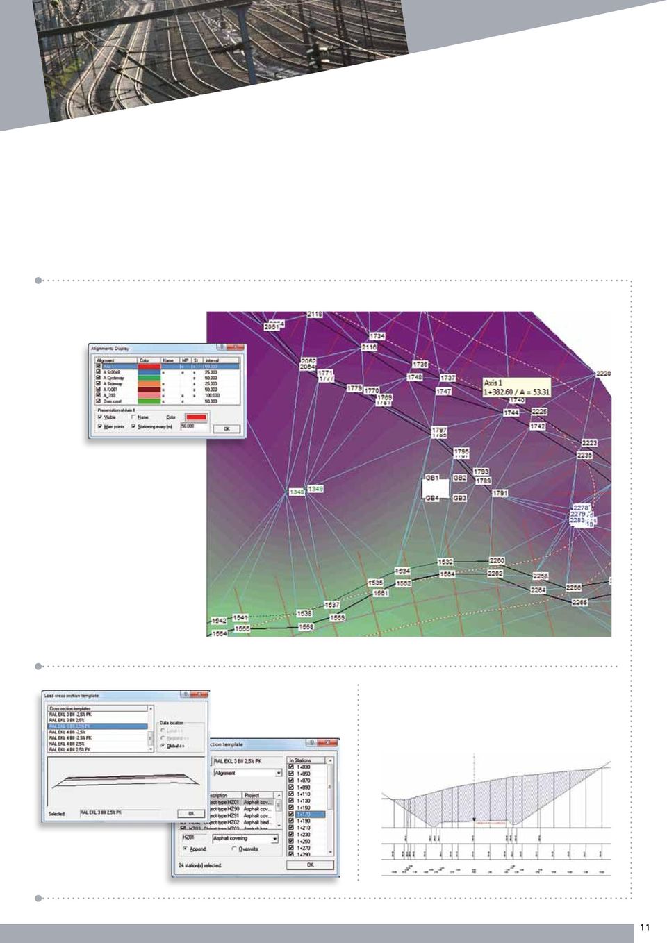
10 Engineering Surveying II Modules: ACHSEN LQPLAN With regard to carrying out volume calculations from cross sections, when constructing roads there are a whole range of positions for which calculations need to be carried out, resulting from the building up of the substrate and the subgrade. The ability to edit cross section designs and constructions directly in the plan window is one of the distinguishing features of CAPLAN. The profile structure is adopted from a cross-section template in which all the profile lines (horizons and Elling lines) are already predefined. CAPLAN represents each alignment with a vertical curve as a triangle in the cross section, so that you can check the suspension of the crosssection templates in the plan immediately. The LQPLAN module can be used to insert cross-section templates individually or simultaneously at several stations. You can design and complete the structures based on the cross-section template and at special stations, as well as integrating the original terrain. For this purpose, LQPLAN provides a range of tools: Add point on left or right hand side of a horizon Insert curve / trench to left or right Free definition of reference point for design construction Insert new horizon / delete horizon Vertically shift / cover a horizon Include intersection points with other profile lines Delete point, move point etc. Create and edit Elling lines Create new profile stations Interpolate intermediate profiles. All design construction operations can be carried out at multiple stations simultaneously if required. Once all the profile lines have been constructed in the plan window, you can transfer the data to the project database and start the volume calculations using the relevant positions. The geometry of road surfaces and profiles is always referenced to an alignment. Normally, the fully-defined alignment is provided by the client. This can be loaded and saved in various formats (e.g. DA 40, LandXML etc.), and manual input is also possible. For special tasks, the ACHSEN module provides additional functionality. The ACHSEN license offers the following: Special transition curves for rail routes (e.g. Bloss and Schuhr curves) Best fit straight line Best fit circle Tangent polygon Spline through specified vertices Alignment-based detail points and setting out Diagnosis of critical points (in 2D and 3D) Intersection between two alignment parallels Perpendicular distances between two alignments Transformation The LQPLAN license offers the following: Creation of profile plans from templates Graphical editing of templates Design and construction of cross sections in the plan window Use of cross-section templates Free definition of cross-section templates Simultaneous editing of multiple profile stations Exchanging of profile data with the project database Interpolation of profiles from points and/or lines Road surfaces with calculations for setting out and performing checks Interpolation of profiles from road surfaces Data exchange interfaces for DA 55, DA 66, LandXML formats etc. The road surface describes the upper surface of a road by means of lane width and crossfall values. There are a range of functions available to assist with the setting out and checking of road surfaces. 10
 are already predefined.")
11 11
12 Processing of Polar Observations Modules: DIRAUS GPUNKT NETZ1L During the processing and evaluation of observation data, CAPLAN always takes the possibility of human error into account. This is in particular the case with regard to the processing of polar or radial (angle and distance) observations, where mistakes such as point mix-ups in the field are unfortunately not uncommon. Surveyors appreciate the automatic plausibility checks that are applied at all stages of the processing, which ensure error detection at an as early stage as possible. The DIRAUS module can be used to process and evaluate raw data from surveying instruments, with all the major manufacturers (Geodimeter, Leica, Sokkia, Stonex, Topcon and Trimble / Zeiss) being supported. Station checks and the subsequent foresight/backsight comparison offer a first opportunity to identify possible point mix-ups. In order to ensure the highest levels of accuracy, new points are calculated in two stages: The first step determines the best possible approximate coordinates, with specific algorithms negating the effects of gross errors and providing remarkably stable results. In the second stage, refined coordinates are determined by carrying out adjustments. The GPUNKT module allows the determination of traverses, as well as the calculation of individual points by means of adjustments applied to redundant measurements. The largely automated determination of new points is also possible, using automatically detected traverses, so that subsequent points will be assigned the best possible coordinates. GPUNKT also caters for the full spectrum of basic surveying tasks, ranging from the calculation of intersections between lines and circles to the carrying out of Helmert transformations and area calculations. Special spatial tasks are solved using 3D objects such as spatial lines, planes, circles, cylinders and spheres. The NETZ1L module can be used to create and adjust 2D plan control networks; for this, it is possible to easily amend the control point conditions and permit all types of network, from completely free networks to fully-constrained networks. In addition to the planning of networks and the forecasting calculations available, breakthrough accuracy prognoses can also be performed when working with tunnel networks. The DIRAUS license offers the following: Field book documentation Setting out documentation Sequential station reduction Processing checks for detecting point name mix-ups Instrument parameters and prism data Hidden point rod Data exchange interfaces for all instrument manufacturers The GPUNKT license offers the following: Orientation / circle reading Traverse calculations Single points and polar points Single point adjustment Processing of polar observations and GNSS baselines Automatic assignment of observation data to control points Recognition of traverses and GNSS traverses Automatic detection of gross errors Detail points and offsets from survey lines and/or polylines Helmert transformations (2D) Intersections between polylines and circles Area computations Computation of building-face points Calculations involving 3D objects Evenness checks pursuant to DIN The NETZ1L license offers the following: Creation and adjustment of any size of plan control networks Free, dynamic and final network adjustment Prognoses for planned control networks Distances, bearings and gyro azimuths Gross error detection Quality assessment of control point coordinates Internal reliability of all observations External reliability of all coordinates Distance analysis with relative error ellipses 12
 being")
13 Visualized observation data Traverse Adjusted 2D plan control network 13

14 Leveling Modules: NIVAUS NETZ1H When very accurate and precise elevations are required, leveling is still the first choice among the various methods of measurement available. The types of leveling range from the simple observation of profiles with a dumpy level to precision leveling using invar leveling staves equipped with barcodes and first order leveling methods used by national surveys. With the NIVAUS module, users can import data from all common automatically-recording instruments (Leica, Topcon, Trimble/Zeiss). Handwritten field book records can also be entered, with support being provided not only for standard leveling but for also for observations made with double scale staves and when working with 3-wire leveling. All checks are carried out as early as possible so as to minimize the risk of point mix-ups. When working with pre-determined control point elevations, NIVAUS automatically compiles leveling runs and loops and distributes any closing errors. Elevation computations carried out for laterally-observed points are so good that they are suitable for many engineering geodesy purposes. In order to provide the basis for evenness checks pursuant to the DIN standard, the leveled points can also be placed in a predefined grid. The NETZ1H module is recommended for elevation calculations requiring the highest possible level of reliability, as this module enables network adjustments to be carried out with a range of control point conditions (free, dynamic and final). For precision networks of the highest order, the height differences are reduced. The normal-orthometric reduction compensates for the non-parallelism of level surfaces, which generally only arises in the north-south direction. The reduction due to gravity anomalies takes local mass inhomogeneities into account, which also affect the level surfaces. The NIVAUS license offers the following: Data import from digital leveling Manual input of field book data Staff calibration (scale, marking line corrections etc.) Use of various staff divisions (e.g. 1/2 cm) Correction for expansion due to temperature Level loop closures with estimation of accuracy Two-peg collimation test Elevation calculations in leveling runs and loops Profile point calculation Grid leveling and evenness checks pursuant to DIN The NETZ1H license offers the following: Creation and adjustment of large leveling networks Normal-orthometric correction Free, dynamic and final adjustments Prognoses for planned leveling networks Gross error detection Quality assessment of control point elevations Internal reliability of all observations External reliability of elevations 14

15 Adjusted vertical network 15

16 GNSS / Transformations Modules: KOTRAN NETZ1R GNSS technology shows its strength in particular with regard to basic networks: it offers homogeneous and high accuracy over the entire project area with relatively low measurement effort. Here, economy and precision meet in perfect harmony. The NETZ1R module extends the options available for performing horizontal and vertical adjustments. With the combined spatial adjustment, it is possible to combine already processed GNSS baselines with classical terrestrial observations (such as total station surveys and leveling) and to integrate them using weighting based on their respective accuracies in order to create a single hybrid spatial network. As a result of the compatibility of all national survey organizations with the WGS / ETRS89 coordinate systems, there are numerous new tasks that can now be solved by CAPLAN with its KOTRAN module. Older coordinate systems can be converted only in approximate terms to the new ETRS89 system when using conformal 3D transformations. For higher accuracy requirements, local inhomogeneities must be taken into account, which can be approximated in many cases by the NTv2 method. CAPLAN offers the common NTv2 approaches, with grid files from respective suppliers being used. The user s own NTv2 grids can also be utilized. The KOTRAN license offers the following: Numerous projections (UTM, Lambert, Stereographic) Transformations between projection zones (zone changes) Transformations to other datums (e.g. ETRS) NTv2 (e.g. BeTA 2007) Import and export of WGS (x, y, z or latitude / longitude) User-defined point data formats Transformation of plans in the plan window Geometrical transformations of point and DXF files (individually or in batches) Meridian convergence and UTM grids Calculation of datum parameters from identical points A range of geoid models (WGS, EGG97, GCG2011 etc.) Control point transformations (Helmert, affine etc.) Distribution of residuals Automatic assignment of control points Parameter transformations without control points Import of GNSS baselines GNSS baseline closure checks Offset corrections for GNSS baselines Calculation of provisional national grid coordinates Recognition of false point names The NETZ1R license offers the following: Combined adjustment of terrestrial survey measurements and GNSS baselines in a national coordinate system Free, dynamic and final adjustments Prognoses for planned spatial networks Distances, bearings and gyro azimuths Level differences, zenith angles and slope distances GNSS baselines Gross error detection Quality assessment of control point coordinates Internal reliability of all observations External reliability of coordinates Distance analysis 16

17 Differences between the conformal transformation DHDN 2001 ETRS89 and the NTv2 approach BeTA 2007 Helmert transformation with distribution of residuals 17

18 Deformation Analysis Module: NETZ2X Horizontal and vertical control surveys of building structures usually consist of an initial survey, made upon completion of the construction, followed by subsequent surveys, carried out at regular time intervals, to monitor possible deformation. Regardless of whether the control is done on a basic network, a structurally-engineered building or a dam, the objects being checked should always be defined using a sufficient number of enduring object points, the position of which can be checked against safe and stable reference points. The NETZ2X license offers the following: Additional functionality for any other current modules in use that are related to adjustments Comparison of two adjusted networks Subdivision into reference and object points Analysis of the reference points with regard to stability Identification and visualization of significant deformations Many documentation procedures are based on a direct comparison of coordinates, which corresponds to a movement analysis. A prerequisite in this regard is that the stability of the reference points is ensured and that a sufficiently accurate determination of the coordinates is performed in every epoch. The movements of the object points over several epochs are preferably illustrated in time-distance diagrams (e.g. settlement measurements), in distance-distance diagrams (e.g. profile movements) or as vector plans (e.g. 2D position shifts). A representation of the movement using sections (in combination with terrain representation) is also possible. The epoch comparison described here is available in the basic CAPLAN module, but the deformation analysis provided in the NETZ2X module goes a crucial step further as it can be used to compare two already adjusted networks. For this, all the points are designated as either reference points or object points, with the reference points being assumed to be stable. The analysis includes the checking of reference points with regard to stability and redesignates non-stable reference points as object points. The changes at all the object points are then documented in a list, together with a statement regarding the statistical significance of the coordinate changes. CAPLAN thereby provides support with regard to interactive enquiries (such as which points have the largest significant deviations? ) and provides comprehensive graphic documentation of the results in diagrams. 18

19 CC and CREDIT Available as a free addition to the CAPLAN license or for individual purchase CC (Cremer Commander) is an Explorer application featuring two directory windows. The right-hand directory window can also be converted into a program window, where shortcuts to other programs can be installed and used to launch the programs. In addition to the clear file management offered by the two directory windows, the comparison and synchronization of two directories (including all subdirectories) is also possible. The CREDIT (Cremer s Editor) program has been specially developed in order to be able to adapt data formats in just a few steps so that they comply with specific data transfer interfaces. A wide range of row and column operations, and also the ability to record sequences of commands as macros, make almost all manual input of data unnecessary. The following is a selection of the special features provided by CREDIT: Search and replace using a table Row filtering (including use of logical statements) and editing Row restructuring, including references to neighboring rows Column-based marking and formatting Column calculations, including references to neighboring rows and columns Macro-recorder for complex operations Syntax and background coloring in order to provide clear visualization of file content Comparison between two files, with interactive editing Definition of named printing configurations 19
 program has been specially developed in order to be able to adapt data formats in just a few steps so that they comply with specific data transfer interfaces.")
20 cremer programmentwicklung gmbh Why use our programs and services? There are many compelling reasons for choosing our products: We have experience in the software development business stretching back more than 20 years, and we place great importance on establishing long term, fruitful relationships with our customers. Our products are independent and are not reliant on other manufacturers of CAD systems. Our extensive, international customer base demonstrates the practical applicability of our software. We are also surveyors and civil engineers, and therefore understand your needs. In terms of support, you can reach the actual developers directly. This allows us to rapidly and competently answer your questions, as well as allowing us to easily make subsequent adjustments to the actual software in order to meet your needs. Your feedback and suggestions contribute to the ongoing development of the software. We react quickly to new requirements, and you can therefore immediately benefit from the resulting program enhancements. We put our time and money into customer assistance and software development, rather than into extensive marketing campaigns. Our prices are realistic and reasonable, so that both you and we benefit in equal measure. Technical details CAPLAN is based in the Windows XP (SP3) / Windows Vista / Windows 7 or newer operating systems, in 32 bit and 64 bit environments. The installation requires about 50 MB of disk space. The amount of RAM required of course depends on the project size 128 MB of free memory provides very good program performance. To enable 3D visualization using the VIS-All application from the company Software-Service John, you need at least 10 GB of disk space, 4GB of RAM and a high quality graphics card. Test version In order to allow you to make a no-risk purchase, we offer an attractively priced test version of CAPLAN which includes the full range of functionality. The test version is only limited in terms of the permitted project size and the duration of use, which is six months. Permanent licenses for the CREDIT (Cremer s Editor) and CC (Cremer Commander) programs are included. If you then order a fully-fledged license during the six month test period, the cost of the test version is refunded. And even in the unlikely event that you do not want to purchase a fully-fledged CAPLAN license, you still have unlimited access to your CREDIT and CC licenses. Training Training sessions can be held at our office or at a location of your choosing. In our experience, it is best to carry out the training not in conjunction with delivery of the software but about 4-6 weeks later. This is because many questions usually arise in the first few weeks of testing and evaluation and these can then be covered during training. Maintenance and support The one year guarantee provided with a purchased copy of the software ensures rectification of any errors reported during that period. This guarantee covers the version of the program purchased, rather than the latest version. We therefore recommend the signing of a CAPLAN support contract when purchasing the software. This includes the provision of regular program updates and gives you access to our CAPLAN support. Authorized distributor: Documentation and help files CAPLAN is delivered with a printed introductory course, which explains the basic concepts using typical surveying projects as examples. More detailed information about the program s functionality is available in the HTML Help that can be accessed directly from the program. The help is context-sensitive (i.e. specific help can be accessed from specific functions), but also serves as an excellent overall reference work due to its extensive cross referencing and indexing. Cremer Programmentwicklung GmbH Türltostraße 16 20, D Pfaffenhofen, Germany Tel: Fax: Mobil: info@cpentw.de,

Available in Base or Survey Standard or Survey Professional series with different modules add-ons to suit your technical requirement and budget.
 World First Leading the Surveying and Civil Engineering software application, civilcad 6 is the world first application of its kind to run in the Plug and Go concept. Delivered pre-installed on a customised
CHAPTER 9 SURVEYING TERMS AND ABBREVIATIONS
 CHAPTER 9 SURVEYING TERMS AND ABBREVIATIONS Surveying Terms 9-2 Standard Abbreviations 9-6 9-1 A) SURVEYING TERMS Accuracy - The degree of conformity with a standard, or the degree of perfection attained
How To Use Gss Software In Trimble Business Center
 Trimble Business Center software technical notes Trimble Business Center Software Makes Processing GNSS Survey Data Effortless Trimble Business Center is powerful surveying office software designed to
Trimble Realworks Software
 TECHNICAL NOTES Trimble Realworks Software A Powerful 3D Laser Scanning Office Software Suite DESIGNED FOR TODAY S MULTIFACETED SCANNING PROFESSIONAL, TRIMBLE REALWORKS IS A POWERFUL OFFICE SOFTWARE THAT
technical notes Trimble business CenTer software trimble BuSineSS Center your Complete office Solution
 Trimble business CenTer software technical notes trimble BuSineSS Center your Complete office Solution trimble Business Center software is your complete office solution for post-processing satellite and
MAGNET Field is a powerful and intuitive field
 MAGNET Field is a powerful and intuitive field application software that enables users to collect survey mapping data and perform construction and road layout using total stations, levels, and GPS. MAGNET
technical notes trimble realworks software
 technical notes trimble realworks software A POWERFUL 3D LASER SCANNING OFFICE SOFTWARE SUITE Designed for today s multifaceted scanning professional, Trimble RealWorks is a powerful office software that
TABLE OF CONTENTS. INTRODUCTION... 5 Advance Concrete... 5 Where to find information?... 6 INSTALLATION... 7 STARTING ADVANCE CONCRETE...
 Starting Guide TABLE OF CONTENTS INTRODUCTION... 5 Advance Concrete... 5 Where to find information?... 6 INSTALLATION... 7 STARTING ADVANCE CONCRETE... 7 ADVANCE CONCRETE USER INTERFACE... 7 Other important
Importing and Opening an Alignment
 Chapter 6 Alignment Files An alignment defines the route of a road, utility line, water way, etc., and is typically comprised of both horizontal and vertical elements. Also, an alignment may include cross-sectional
GEOGRAPHIC INFORMATION SYSTEMS CERTIFICATION
 GEOGRAPHIC INFORMATION SYSTEMS CERTIFICATION GIS Syllabus - Version 1.2 January 2007 Copyright AICA-CEPIS 2009 1 Version 1 January 2007 GIS Certification Programme 1. Target The GIS certification is aimed
Pro/ENGINEER Wildfire 4.0 Basic Design
 Introduction Datum features are non-solid features used during the construction of other features. The most common datum features include planes, axes, coordinate systems, and curves. Datum features do
TechnicalNotes. Terramodel Software for Construction
 TechnicalNotes Terramodel Software for Construction INTEGRATED SOFTWARE FOR IMPROVED CONSTRUCTION PROCESSES Today s construction industry demands high accuracy and maximum efficiency throughout the construction
The Map Grid of Australia 1994 A Simplified Computational Manual
 The Map Grid of Australia 1994 A Simplified Computational Manual The Map Grid of Australia 1994 A Simplified Computational Manual 'What's the good of Mercator's North Poles and Equators, Tropics, Zones
technical notes TRIMBLE SURVEY MANAGER SOFTWARE
 TRIMBLE SURVEY MANAGER SOFTWARE technical notes The Trimble survey manager software is a powerful Field and office software for the collection, processing, and visualization of data collected during precise
Road Rehabilitation and Reconstruction Using AutoCAD Civil 3D
 Road Rehabilitation and Reconstruction Using AutoCAD Civil 3D Contents Introduction... 3 Introduction to Corridor Targets... 3 Surface Targets... 4 Width and Offset Targets... 5 Elevation or Slope Targets...
NJDEP GPS Data Collection Standards For GIS Data Development
 NJDEP GPS Data Collection Standards For GIS Data Development Bureau of Geographic Information Systems Office of Information Resource Management June 8, 2011 1.0 Introduction... 3 2.0 GPS Receiver Hardware
This high level land planning and design system will replace the land
 Performance Planning System () The following is a v1.3 feature analysis, which clarifies differences, between and American Planning Association (APA) Land Based Classification Standards (LBCS) for color
Introduction. www.imagesystems.se
 Product information Image Systems AB Main office: Ågatan 40, SE-582 22 Linköping Phone +46 13 200 100, fax +46 13 200 150 info@imagesystems.se, Introduction Motion is the world leading software for advanced
PLOTTING SURVEYING DATA IN GOOGLE EARTH
 PLOTTING SURVEYING DATA IN GOOGLE EARTH D M STILLMAN Abstract Detail surveys measured with a total station use local coordinate systems. To make the data obtained from such surveys compatible with Google
Autodesk Civil 3D Styles: A Guide to the Fundamentals
 AUTODESK CIVIL 3D WHITE PAPER Autodesk Civil 3D Styles: A Guide to the Fundamentals About the Author: Mark Scacco, PE, is the founder and president of Engineered Efficiency, Inc., a technology consulting
STATE CONTROL SURVEY SPECIFICATIONS FOR PRIMARY CONTROL SURVEYS. Now Obsolete
 STATE CONTROL SURVEY SPECIFICATIONS FOR PRIMARY CONTROL SURVEYS Now Obsolete Caution: This document has been prepared by scanning the original Specifications for Primary Control Surveys - 1984 and using
New Features in TerraScan. Arttu Soininen Software developer Terrasolid Ltd
 New Features in TerraScan Arttu Soininen Software developer Terrasolid Ltd Version 013.xxx Computer ID changes in licenses Send new computer ID to Terrasolid if using: Server pool licenses (server ID and
How To Draw In Autocad
 DXF Import and Export for EASE 4.0 Page 1 of 9 DXF Import and Export for EASE 4.0 Bruce C. Olson, Dr. Waldemar Richert ADA Copyright 2002 Acoustic Design Ahnert EASE 4.0 allows both the import and export
Introduction to GIS (Basics, Data, Analysis) & Case Studies. 13 th May 2004. Content. What is GIS?
 & Case Studies. 13 th May 2004. Content. What is GIS?") Introduction to GIS (Basics, Data, Analysis) & Case Studies 13 th May 2004 Content Introduction to GIS Data concepts Data input Analysis Applications selected examples What is GIS? Geographic Information
Introduction to GIS (Basics, Data, Analysis) & Case Studies 13 th May 2004 Content Introduction to GIS Data concepts Data input Analysis Applications selected examples What is GIS? Geographic Information
Introduction to Trimble Access. The Next Generation of Survey Controller S-0102
 Introduction to Trimble Access The Next Generation of Survey Controller S-0102 Questions we will answer What is Trimble Access? A suite of software applications How do they all fit together? How does it
Data source, type, and file naming convention
 Exercise 1: Basic visualization of LiDAR Digital Elevation Models using ArcGIS Introduction This exercise covers activities associated with basic visualization of LiDAR Digital Elevation Models using ArcGIS.
Digital Terrain Model Grid Width 10 m DGM10
 Digital Terrain Model Grid Width 10 m Status of documentation: 23.02.2015 Seite 1 Contents page 1 Overview of dataset 3 2 Description of the dataset contents 4 3 Data volume 4 4 Description of the data
Survey Ties Guidelines
 North Carolina Board of Examiners for Engineers and Surveyors Survey Ties Guidelines The North Carolina Board of Examiners for Engineers and Surveyors is providing this document to serve as an interpretative
04 / 2012. Panel Design Configurator The modular planning software for low voltage distribution systems
 04 / 2012 Panel Design Configurator The modular planning software for low voltage distribution systems Panel Design Configurator an all-round solution for project planning Panel Design Configurator is
An introduction to 3D draughting & solid modelling using AutoCAD
 An introduction to 3D draughting & solid modelling using AutoCAD Faculty of Technology University of Plymouth Drake Circus Plymouth PL4 8AA These notes are to be used in conjunction with the AutoCAD software
Introduction to CATIA V5
 Introduction to CATIA V5 Release 16 (A Hands-On Tutorial Approach) Kirstie Plantenberg University of Detroit Mercy SDC PUBLICATIONS Schroff Development Corporation www.schroff.com www.schroff-europe.com
RESEARCH PAPERS FACULTY OF MATERIALS SCIENCE AND TECHNOLOGY IN TRNAVA SLOVAK UNIVERSITY OF TECHNOLOGY IN BRATISLAVA
 RESEARCH PAPERS FACULTY OF MATERIALS SCIENCE AND TECHNOLOGY IN TRNAVA SLOVAK UNIVERSITY OF TECHNOLOGY IN BRATISLAVA 2010 Number 29 3D MODEL GENERATION FROM THE ENGINEERING DRAWING Jozef VASKÝ, Michal ELIÁŠ,
Welcome to CorelDRAW, a comprehensive vector-based drawing and graphic-design program for the graphics professional.
 Workspace tour Welcome to CorelDRAW, a comprehensive vector-based drawing and graphic-design program for the graphics professional. In this tutorial, you will become familiar with the terminology and workspace
Model based quality assurance process in a infra construction. Case Riippa-Eskola RU2 double rail project
 Model based quality assurance process in a infra construction project Case Riippa-Eskola RU2 double rail project M. Jaakkola a and P. Toppi a a Destia Ltd, Development of Infra construction, Finland E-mail:
Understand the Sketcher workbench of CATIA V5.
 Chapter 1 Drawing Sketches in Learning Objectives the Sketcher Workbench-I After completing this chapter you will be able to: Understand the Sketcher workbench of CATIA V5. Start a new file in the Part
TRIMBLE ENGINEERING SOLUTION TUNNELS AND MONITORING
 TRIMBLE ENGINEERING SOLUTION TUNNELS AND MONITORING ERIK SCHÜTZ & TOMAS LARSSON TRIMBLE ENGINEERING & CONSTRUCTION GROUP WESTMINSTER, COLORADO, USA DECEMBER 2007 Trimble Engineering & Construction Group,
IP-S3 HD1. Compact, High-Density 3D Mobile Mapping System
 IP-S3 HD1 Compact, High-Density 3D Mobile Mapping System Integrated, turnkey solution Ultra-compact design Multiple lasers minimize scanning shades Unparalleled ease-of-use No user calibration required
How To Create A View Frame In 3D
 12/4/2008-10:00 am - 11:30 am Room:Palazzo O-P (5th) The Secrets of Cutting Plan and Profile Sheets in AutoCAD Civil 3D Michelle Rasmussen - Application Engineer, IMAGINiT Technologies CV304-1P In this
GEOENGINE MSc in Geomatics Engineering (Master Thesis) Anamelechi, Falasy Ebere
 Anamelechi, Falasy Ebere") Master s Thesis: ANAMELECHI, FALASY EBERE Analysis of a Raster DEM Creation for a Farm Management Information System based on GNSS and Total Station Coordinates Duration of the Thesis: 6 Months Completion
Master s Thesis: ANAMELECHI, FALASY EBERE Analysis of a Raster DEM Creation for a Farm Management Information System based on GNSS and Total Station Coordinates Duration of the Thesis: 6 Months Completion
Files Used in this Tutorial
 Generate Point Clouds Tutorial This tutorial shows how to generate point clouds from IKONOS satellite stereo imagery. You will view the point clouds in the ENVI LiDAR Viewer. The estimated time to complete
SURVEYING WITH GPS. GPS has become a standard surveying technique in most surveying practices
 SURVEYING WITH GPS Key Words: Static, Fast-static, Kinematic, Pseudo- Kinematic, Real-time kinematic, Receiver Initialization, On The Fly (OTF), Baselines, Redundant baselines, Base Receiver, Rover GPS
The process components and related data characteristics addressed in this document are:
 TM Tech Notes Certainty 3D November 1, 2012 To: General Release From: Ted Knaak Certainty 3D, LLC Re: Structural Wall Monitoring (#1017) rev: A Introduction TopoDOT offers several tools designed specifically
Leica SmartWorx Viva Software Release Notes
 Leica SmartWorx Viva Software Release Notes Release Details: Version 5.05 Release date 13 March 2014 Available for: Products Field Controllers: CS10, CS15 Total Stations: TS11, TS15, TM50, TS50, MS50 GNSS
IP-S2 Compact+ 3D Mobile Mapping System
 IP-S2 Compact+ 3D Mobile Mapping System 3D scanning of road and roadside features Delivers high density point clouds and 360 spherical imagery High accuracy IMU options without export control Simple Map,
REPORT OF WORK GUIDELINES
 REPORT OF WORK GUIDELINES The following guidelines apply to a report of work submitted under section 56(1) of the Mining Act (http://laws.gnb.ca/en/showdoc/cs/m-14.1). 1 (1) A report of work shall be submitted
Pro/ENGINEER Wildfire 5.0 Introduction to Surface Modeling
 Introduction Several advanced surface types are available as listed below. Variable Section Sweep Boundary Blend Section to Surfaces Blend Surface to Surface Blend A surface is created by sweeping a single
GIS Spatial Data Standards
 GIS Spatial Data Standards Manatee County, FL GIS Section, Information Services Department TABLE OF CONTENTS I. Introduction 2 A. Purpose 2 B. Reference 2 II. Spatial Reference Information 2 A. Projection:
WHAT YOU NEED TO USE THE STATE PLANE COORDINATE SYSTEMS
 WHAT YOU NEED TO USE THE STATE PLANE COORDINATE SYSTEMS N & E State Plane Coordinates for Control Points AZIMUTHS - True, Geodetic, or Grid - Conversion from Astronomic to Geodetic (LaPlace Correction)
AutoCAD 2009. New Icon Quick Reference
 AutoCAD 2009 New Quick Reference Contents Chapter 1 New Quick Reference..................... 1 Toolbars................................... 1 3D Navigation Toolbar........................ 1 CAD Standards
The user forum is an excellent community in which to bounce questions off other professional users, like you.
 INTRODUCTION Thank you for your interest in MicroSurvey Point Prep Point Prep is a simple to use desktop based product designed specifically for the construction layout professional. Point Prep is used
TILOS GETTING STARTED & EXERCISES
 TILOS GETTING STARTED & EXERCISES 1. Release 2010-03 TILOS 7.0 Created by Linear project GmbH Training Support Software Development For further information please contact: ----------------------------------------------------------------------------------------------
Earth Coordinates & Grid Coordinate Systems
 Earth Coordinates & Grid Coordinate Systems How do we model the earth? Datums Datums mathematically describe the surface of the Earth. Accounts for mean sea level, topography, and gravity models. Projections
Visualization of 2D Domains
 Visualization of 2D Domains This part of the visualization package is intended to supply a simple graphical interface for 2- dimensional finite element data structures. Furthermore, it is used as the low
Technical Drawing Specifications Resource A guide to support VCE Visual Communication Design study design 2013-17
 A guide to support VCE Visual Communication Design study design 2013-17 1 Contents INTRODUCTION The Australian Standards (AS) Key knowledge and skills THREE-DIMENSIONAL DRAWING PARALINE DRAWING Isometric
John F. Cotton College of Architecture & Environmental Design California Polytechnic State University San Luis Obispo, California JOHN F.
 SO L I DMO D E L I N GAS A TO O LFO RCO N S T RU C T I N SO G LA REN V E LO PE S by John F. Cotton College of Architecture & Environmental Design California Polytechnic State University San Luis Obispo,
Creating Drawings in Pro/ENGINEER
 6 Creating Drawings in Pro/ENGINEER This chapter shows you how to bring the cell phone models and the assembly you ve created into the Pro/ENGINEER Drawing mode to create a drawing. A mechanical drawing
Lab 3. GIS Data Entry and Editing.
 Lab 3. GIS Data Entry and Editing. The goal: To learn about the vector (arc/node) and raster data types entry and editing. Objective: Create vector and raster datasets and visualize them. Software for
What's New in Heavy Civil Construction Software. Chris Richardson HCC-6898
 What's New in Heavy Civil Construction Software Chris Richardson HCC-6898 Segment Initiatives Make it simple Easy to use Integrated with the Heavy Civil Construction portfolio Workflow improvements Provide
AutoCAD Civil 3D 2010 ESSENTIALS
 AutoCAD Civil 3D 2010 ESSENTIALS SDC PUBLICATIONS Schroff Development Corporation www.schroff.com Better Textbooks. Lower Prices. Visit our website to learn more about this and other books: AutoCAD Civil
Certified Translation from German
 Certified Translation from German Annexes to the Agreements Table of contents Annex 1 Scope of the licence Annex 2 System Requirements Annex 3 Modules Annex 4 Hotline hours Annex 5 Trainings Annex 6 Price
In mathematics, there are four attainment targets: using and applying mathematics; number and algebra; shape, space and measures, and handling data.
 MATHEMATICS: THE LEVEL DESCRIPTIONS In mathematics, there are four attainment targets: using and applying mathematics; number and algebra; shape, space and measures, and handling data. Attainment target
Information Server Documentation SIMATIC. Information Server V8.0 Update 1 Information Server Documentation. Introduction 1. Web application basics 2
 Introduction 1 Web application basics 2 SIMATIC Information Server V8.0 Update 1 System Manual Office add-ins basics 3 Time specifications 4 Report templates 5 Working with the Web application 6 Working
A HYBRID APPROACH FOR AUTOMATED AREA AGGREGATION
 A HYBRID APPROACH FOR AUTOMATED AREA AGGREGATION Zeshen Wang ESRI 380 NewYork Street Redlands CA 92373 Zwang@esri.com ABSTRACT Automated area aggregation, which is widely needed for mapping both natural
What s New V 11. Preferences: Parameters: Layout/ Modifications: Reverse mouse scroll wheel zoom direction
 What s New V 11 Preferences: Reverse mouse scroll wheel zoom direction Assign mouse scroll wheel Middle Button as Fine tune Pricing Method (Manufacturing/Design) Display- Display Long Name Parameters:
CATIA Wireframe & Surfaces TABLE OF CONTENTS
 TABLE OF CONTENTS Introduction... 1 Wireframe & Surfaces... 2 Pull Down Menus... 3 Edit... 3 Insert... 4 Tools... 6 Generative Shape Design Workbench... 7 Bottom Toolbar... 9 Tools... 9 Analysis... 10
Video Tracking Software User s Manual. Version 1.0
 Video Tracking Software User s Manual Version 1.0 Triangle BioSystems International 2224 Page Rd. Suite 108 Durham, NC 27703 Phone: (919) 361-2663 Fax: (919) 544-3061 www.trianglebiosystems.com Table of
Creating 2D Drawings from 3D AutoCAD Models
 Creating 2D Drawings from 3D AutoCAD Models David Piggott CrWare, LP GD205-2P This class explores the various techniques in creating 2D part and assembly drawings from 3D AutoCAD models. As part of the
CATIA V5R21 - FACT SHEET
 CATIA V5R21 - FACT SHEET Introduction What s New at a Glance Overview Detailed Description INTRODUCTION CATIA V5 is the leading solution for product success. It addresses all manufacturing organizations;
Getting Started With DraftSight A Guide For AEC Users
 Getting Started With DraftSight A Guide For AEC Users DraftSight.com Facebook.com/DraftSight Welcome to DraftSight a valuable tool for any AEC professional! DraftSight is more than a free, professional-grade
AutoCAD Civil 3D Profile Views, Data Bands, and Styles
 AutoCAD Civil 3D Profile Views, Data Bands, and Styles Thomas Martin UDS Urbane Daten-Systeme GmbH Roman Börnchen UDS Urbane Daten-Systeme GmbH CI4513 How do I get a profile view that meets my expectations?
com www. IRRIEXPRESS IRRIGATION DESIGN SOFTWARE
 Established 1963 IRRIEXPRESS IRRIGATION DESIGN SOFTWARE Create And Validate Irrigation Designs In Minutes. Design comprehensive irrigation projects with pivots, sprinklers and drip using a simple, intuitive
MGL Avionics. MapMaker 2. User guide
 MGL Avionics MapMaker 2 User guide General The MGL Avionics MapMaker application is used to convert digital map images into the raster map format suitable for MGL EFIS systems. Note: MapMaker2 produces
Design document Goal Technology Description
 Design document Goal OpenOrienteering Mapper is a program to draw orienteering maps. It helps both in the surveying and the following final drawing task. Support for course setting is not a priority because
How SolidWorks Speeds Consumer Product Design
 white paper How SolidWorks Speeds Consumer Product Design inspiration SUMMARY SolidWorks Premium bridges the gap between industrial design and engineering by providing powerful surfacing capabilities,
Geomagic Design. Release Notes. Get to Market Faster with Better Products at a Lower Cost V17
 Geomagic Design Get to Market Faster with Better Products at a Lower Cost Release Notes V17 TABLE OF CONTENTS 1 INTRODUCTION 1 COPYRIGHT 1 2 INSTALLATION 2 SOFTWARE IDENTIFICATION 2 UPGRADING TO GEOMAGIC
 Edinburgh COLLEGE of ART ARCHITECTURE 3D Modelling in AutoCAD - tutorial exercise The screen The graphics area This is the part of the screen in which the drawing will be created. The command prompt area
LONGITUDINAL PROFILE COMPLETION
 LONGITUDINAL PROFILE COMPLETION Course of the trench bottom determine using drawn cross-sections plot (refer to fig. 0630) according to the stationing direction: right-sided... dotted line left-sided...
siemens.com/mobility Sitraffic Office The integrated workstation for traffic engineers
 siemens.com/mobility Sitraffic Office The integrated workstation for traffic engineers A single software system for use by the traffic engineer, the operator and the service technician? Welcome to the
Industrial IT Ó Melody Composer
 Overview Industrial IT Ó Melody Composer Features and Benefits Support of concurrent engineering for Control Systems Operation on Windows NT and Windows 2000 Multiple client/server architecture Off-Line
Total Program's Units
 Associate Degree Program Department of Civil and Architectural Technology Major : Survey Technology First Semester NO 5 6 Code SRV 0 SRV 0 SRV 0 ENG 0 MTH 7 CMT 0 Course Title Land survey Survey drawing
NEW DIGITAL TERRAIN MODELING (DTM) TOOLS FOR CABLE ROUTE PLANNING by Dr. Jose M. Andres Makai Ocean Engineering Inc.
 TOOLS FOR CABLE ROUTE PLANNING by Dr. Jose M. Andres Makai Ocean Engineering Inc.") NEW DIGITAL TERRAIN MODELING (DTM) TOOLS FOR CABLE ROUTE PLANNING by Dr. Jose M. Andres Makai Ocean Engineering Inc. EXISTING CABLE ROUTE PLANNING TOOLS In recent years, methods used for submarine cable
NEW DIGITAL TERRAIN MODELING (DTM) TOOLS FOR CABLE ROUTE PLANNING by Dr. Jose M. Andres Makai Ocean Engineering Inc. EXISTING CABLE ROUTE PLANNING TOOLS In recent years, methods used for submarine cable
Machine Tool Control. Besides these TNCs, HEIDENHAIN also supplies controls for other areas of application, such as lathes.
 Machine Tool Control Contouring controls for milling, drilling, boring machines and machining centers TNC contouring controls from HEIDENHAIN for milling, drilling, boring machines and machining centers
ExpertCAD Release Summary March 2010
 Overview ExpertCAD Release Summary March 2010 ExpertCAD 2010 is major release that includes significant enhancements as well as customer requested software modifications and corrections. This release summary
Title 10 DEPARTMENT OF NATURAL RESOURCES Division 35 Land Survey Chapter 1 Cadastral Mapping Standards
 Title 10 DEPARTMENT OF NATURAL RESOURCES Division 35 Land Survey Chapter 1 Cadastral Mapping Standards 10 CSR 35-1.010 Application of Standards PURPOSE: These minimum standards provide the digital mapper
Guideline for Control Surveys by Differential Levelling
 Guideline for Control Surveys by Differential Levelling Special Publication 1 Intergovernmental Committee on Surveying and Mapping (ICSM) Permanent Committee on Geodesy (PCG) 24 September 2014 Intergovernmental
3 LEVELLING & SURVEYING
 3 LEVELLING & SURVEYING 3.1 General The primary reference at water-level recording stations is a set of stable bench-marks, installed in locations where their level should not change. Upon initial set-up
Create a folder on your network drive called DEM. This is where data for the first part of this lesson will be stored.
 In this lesson you will create a Digital Elevation Model (DEM). A DEM is a gridded array of elevations. In its raw form it is an ASCII, or text, file. First, you will interpolate elevations on a topographic
SESSION 8: GEOGRAPHIC INFORMATION SYSTEMS AND MAP PROJECTIONS
 SESSION 8: GEOGRAPHIC INFORMATION SYSTEMS AND MAP PROJECTIONS KEY CONCEPTS: In this session we will look at: Geographic information systems and Map projections. Content that needs to be covered for examination
Pipeline External Corrosion Analysis Using a 3D Laser Scanner
 Pipeline Technology Conference 2013 Pipeline External Corrosion Analysis Using a 3D Laser Scanner Pierre-Hugues ALLARD, Charles MONY Creaform, www.creaform3d.com 5825 rue St-Georges, Lévis (QC), Canada,
TRIMBLE ATS TOTAL STATION ADVANCED TRACKING SYSTEMS FOR HIGH-PRECISION CONSTRUCTION APPLICATIONS
 TRIMBLE ATS TOTAL STATION ADVANCED TRACKING SYSTEMS FOR HIGH-PRECISION CONSTRUCTION APPLICATIONS BY MARTIN WAGENER APPLICATIONS ENGINEER, TRIMBLE EUROPE OVERVIEW Today s construction industry demands more
ELFRING FONTS INC. MICR FONTS FOR WINDOWS
 ELFRING FONTS INC. MICR FONTS FOR WINDOWS This package contains ten MICR fonts (also known as E-13B) used to print the magnetic encoding lines on checks, and eight Secure Fonts for use in printing check
Advanced Surface Modeling
 This sample chapter is for review purposes only. Copyright The Goodheart-Willcox Co., Inc. ll rights reserved. Chapter dvanced Modeling Learning Objectives fter completing this chapter, you will be able
The following is an overview of lessons included in the tutorial.
 Chapter 2 Tutorial Tutorial Introduction This tutorial is designed to introduce you to some of Surfer's basic features. After you have completed the tutorial, you should be able to begin creating your
Part Number: PMT1080-ENG Rev. 1
 2010 Dassault Systèmes, All Rights Reserved DraftSight and the DraftSight logos are trademarks of Dassault Systèmes or its subsidiaries in the US and/or other countries. Other brand or product names are
Using Spreadsheets, Selection Sets, and COGO Controls
 Using Spreadsheets, Selection Sets, and COGO Controls Contents About this tutorial... 3 Step 1. Open the project... 3 Step 2. View spreadsheets... 4 Step 3. Create a selection set... 10 Step 4. Work with
How To Fuse A Point Cloud With A Laser And Image Data From A Pointcloud
 REAL TIME 3D FUSION OF IMAGERY AND MOBILE LIDAR Paul Mrstik, Vice President Technology Kresimir Kusevic, R&D Engineer Terrapoint Inc. 140-1 Antares Dr. Ottawa, Ontario K2E 8C4 Canada paul.mrstik@terrapoint.com
ME 111: Engineering Drawing
 ME 111: Engineering Drawing Lecture # 14 (10/10/2011) Development of Surfaces http://www.iitg.ernet.in/arindam.dey/me111.htm http://www.iitg.ernet.in/rkbc/me111.htm http://shilloi.iitg.ernet.in/~psr/ Indian
Map Patterns and Finding the Strike and Dip from a Mapped Outcrop of a Planar Surface
 Map Patterns and Finding the Strike and Dip from a Mapped Outcrop of a Planar Surface Topographic maps represent the complex curves of earth s surface with contour lines that represent the intersection
1 Basic concepts of surveying
 1 Basic concepts of surveying The aim of this chapter is to introduce the reader to the basic concepts of surveying. It is therefore the most important chapter and worthy of careful study and consideration.
INDEX. SR NO NAME OF THE PRACTICALS Page No. Measuring the bearing of traverse lines, calculation of included angles and check.
 INDEX SR NO NAME OF THE PRACTICALS Page No 1 Measuring the bearing of traverse lines, calculation of included angles and check. 1 2 To study the essential parts of dumpy level & reduction of levels 3 To