|
|
|
- Lucas Walton
- 7 years ago
- Views:
Transcription


1

2

3

4


5


6
7 ABTQ-31 rev 07 Last review: 14 January 2013 INSTALLATION, OPERATION & MAINTENANCE f ABTECH BUSBAR BOX SIRA99ATEX3177 and IECEx SIR Marking The marking shown is f an apparatus certified BusBar Box. BUSBAR BOX W kv SERIAL No. S / 20 Ex e IIC T Gb Ex tb IIIC T C Db II 2 GD - IP66 (-40ºC=Tamb=+40ºC) SIRA 99ATEX IECEx SIR WARNING!!! ISOLATE ELSEWHERE BEFORE OPENING ENCLOSURE The maximum permitted voltage is 11kV. An alternative version is available f a maximum operating voltage of 8.8 kv. If the bus bar mounting frame is disturbed after manufacture the maximum voltage is automatically de-rated to 8.8 kv The maximum permitted power dissipation is marked on the label and identified by RATING W. The table to the right shows the possible combinations of marking. Alternative markings are Ex e IIC T6 Gb Ex tb IIIC T 65 C Db (-40ºC=Tamb=+60ºC) Power dissipation = 74.7W Ex e IIC T6 Gb Ex tb IIIC T 55 C Db (-40ºC=Tamb=+40ºC) Power dissipation = 74.7W Ex e IIC T5 Gb Ex tb IIIC T 55 C Db (-40ºC=Tamb=+40ºC) Power dissipation = 167.5W F 6 conducts per phase Ex e IIC T6 Gb Ex tb IIIC T 65 C Db (-40ºC=Tamb=+60ºC) Power dissipation = 73.6W Ex e IIC T5 Gb Ex tb IIIC T 56 C Db (-40ºC=Tamb=+45ºC) Power dissipation = 145.8W Ex e IIC T6 Gb Ex tb IIIC T 51 C Db (-40ºC=Tamb=+40ºC) Power dissipation = 132.0W Ex e IIC T5 Gb Ex tb IIIC T 63 C Db (-40ºC=Tamb=+40ºC) Power dissipation = 192.0W Installation Each BUSBAR box requires mechanical suppt from the underside. The mass of a typical BUSBAR box is 270 kg The unsuppted mass of the cables should be added. It is recommended that the enclosure also be secured to a substantial vertical surface. It is recommended that the bus bar closest to the do be selected as the neutral (where applicable) followed by the phases red (Brown), yellow (grey) and blue (black) wking towards the rear of the box. If the wiring system does not include a neutral then the bus bar nearest the do may be used f earthing/grounding not used at all. Two fmats are available :- 1 - BUSBAR box f single ce cables. This design allows f either a through connection (in at the bottom, out at the top) side connection (in and out at bottom only top only). single 2 - BUSBAR box f multi-ce cables. This design permits only single side connection and incpates the use of a trifurcating box to allow the splitting of a multi-ce cable into single ces befe they enter the bus bar chamber. 1 BUSBAR box f single ce cables A.B. Controls and Technology Ltd, Sanderson Street, Lower Don Valley, Sheffield S9 2UA England 1 / 4
8 ABTQ-31 rev 07 Last review: 14 January 2013 INSTALLATION, OPERATION & MAINTENANCE f ABTECH BUSBAR BOX SIRA99ATEX3177 and IECEx SIR a) Mount the enclosure on the suppt frame and secure b) Open and remove the lid. c) Remove the machine screws securing the blank gland plate opposite the first cable entry gland plate to be used. This will allow essential access to the bus bar. d) Check that the bus bar clamp securing nut spring washers are fully compressed. It should not be necessary to adjust these but if necessary the tightening tque is 10Nm minimum, 15Nm maximum. e) Attach the cable glands to the gland plate in accdance with the manufacturer s instructions. f) Prepare the first cable in accdance with the cable gland manufacturer s instructions. (This should be one of the cable ces f the blue phase f attachment to the rearmost bus bar). Leave sufficient length of cable ce and ce insulation to comftably reach the crimp type terminal supplied. Remember to include the length of the crimping barrel. g) Insert the cable through the cable gland and secure the armouring (if applicable) in accdance with the gland manufacturers instructions. If a stuffing gland is used secure the cable by tightening the sealing nut. h) Carefully mark the cable to length so that the conduct will reach the stop on the inside of the crimping lug barrel. The cable ce should have no intentional bends. The cable gland used should be directly below ( above f top entry) the crimping lug barrel. i) Remove the cable from the gland and trim the conduct to length. j) Cut back the conduct insulation. The length of the exposed conduct should be no me than 5mm longer than the internal length of the crimping lug barrel. k) Insert the cable through the appropriate cable gland again and into the barrel of the crimping lug to check f crect length. If armoured cable is used check that the armouring will clamp in the cable gland as intended by the gland manufacturer. l) Once the crect length has been established make careful note of all the cable stripping lengths f repeat use. m) Remove the applicable crimping lug from the bus bar assembly. n) Partially Insert the cable ce through the appropriate cable gland again and push the crimping lug onto the conduct. o) Rotate the crimping lug so that the face which contacts with the bus bar is both facing and parallel to the rear of the box. p) Crimp the barrel onto the conduct using the crect size crimping die set. This may be of the indenting hexagonal type. q) Lift the cable and lug to just below the bus bar assembly and insert the M20 x 55 mm high tensile steel bolt through the hole in the palm of the lug. r) Lift further until the bolt will locate in the fixing hole in the bus bar assembly. s) Push the bolt through the bus bar assembly and secure the lug in place with the nut. Tighten moderately and check again that the cable gland will adequately clamp the cable armour as intended by the gland manufacturer. DO NOT CLAMP THE ARMOUR AT THIS TIME. t) Using the measurement notes taken of the now installed cable prepare each of the other cables. u) Repeat from j), (above), checking f length against the prepared cable and lug assembly, then l), m), n) & o). v) Once all the cables have been installed apply a tque of 185Nm to each connection bolt. w) Replace both of the undrilled (blank) gland plates complete with gaskets and secure the M8 gland plate fixings to 6Nm approx. x) Replace the enclosure lid. The ABTECH BUSBAR BOX is now ready f use. F operation and maintenance see page 4 2 BUSBAR box f multi-ce cables The BUSBAR box f multi-ce cables is generally supplied with a trifurcating box. a) Mount the BUSBAR box assembly complete with trifurcating box on the suppt frame and secure. b) Remove the do from both boxes. c) Fit the cable gland f one of the incoming multi-ce cables to the base gland plate of the trifurcating box. d) Fit the cable glands f each ce of the multi-ce cable to the underside of the gland plate separating the BUSBAR box and the trifurcating box. e) Remove the top plate of the BUSBAR box. A.B. Controls and Technology Ltd, Sanderson Street, Lower Don Valley, Sheffield S9 2UA England 2 / 4
9 ABTQ-31 rev 07 Last review: 14 January 2013 INSTALLATION, OPERATION & MAINTENANCE f ABTECH BUSBAR BOX SIRA99ATEX3177 and IECEx SIR f) Check that the bus bar clamp securing nut spring washers are fully compressed. It should not be necessary to adjust these but if necessary the tightening tque is 10Nm minimum, 15Nm maximum. g) Prepare the first multi-ce cable in accdance with the cable gland manufacturer s instructions. Leave sufficient length of cable ce and ce insulation to comftably reach each of the crimp type phase terminals supplied. Remember to include the length of the crimping barrel f each terminal. h) Insert the multi-ce cable through the cable gland in the base gland plate of the trifurcating box, When sufficient cable has been drawn through thread each ce through its applicable gland in the gland plate separating the BUSBAR box and the trifurcating box. Ensure the crect phase connection befe proceeding further. i) Draw through the remainder of the multi-ce cable and secure the armouring (if applicable) in accdance with the manufacturers instructions. If a stuffing gland is used secure the multi-ce cable by tightening the sealing nut. j) Carefully mark each ce to length so that the conduct will reach the stop on the inside of the applicable crimping lug barrel. (The cable ce should have no intentional bends inside the BUSBAR box. All cable ce bending must be within the trifurcating box. The cable gland used f each ce should be directly below the crimping lug barrel). k) Unscrew the securing nut f the multi-ce cable gland and withdraw the gland and cable until the individual ces are accessible within the BUSBAR box. l) Trim each ce to length as marked. m) Cut back the conduct ce insulation f each ce. The length of the exposed conduct should be no me than 5mm longer that the internal length of the crimping lug barrel. n) Draw the multi-ce back up through the base gland plate of the trifurcating box and secure the gland again. o) Check each individual cable ce f length against its crimping lug. p) Once the crect length has been established f each ce make careful note of all the cable stripping lengths f repeated use. q) Again, unscrew the securing nut f the multi-ce cable gland and withdraw the gland and cable until the individual ces are accessible within the BUSBAR box. r) Remove the applicable crimping lugs from the bus bar assembly. s) Push the appropriate crimping lug onto each conduct and rotate each lug so that the face which contacts with the bus bar is both facing and parallel to the rear of the box. t) Crimp the barrel of each lug onto the conduct using the crect size crimping die set. This may be of the indenting hexagonal type. u) Lift the cable ces together until the lugs are just below the bus bar assembly and insert an M20 x 55mm high tensile steel bolt through the hole in the palm of each lug. v) Lift the cable ces further until the fixing bolts will locate in the bus bar assembly. w) F each cable ce lug push the bolt through the bus bar assembly and secure the lug in place with the nut. Tighten moderately. x) Check that the gland f the multi-ce cable will secure in its mounting hole. Do not secure the gland at this time. y) Using the noted measurements taken earlier from the now installed cable, prepare each of the other cables. z) Remove the bolts securing the assembled cable to the bus bar and withdraw the multi-ce cable and gland until the lugs rest on the gland plate that separates the BUSBAR box from the trifurcating box. aa) Repeat g) above then repeat from q) to s) f each cable. bb) When all cables have been prepared to stage s) continue with stage t), u) & v). Secure the glands f the multi-ce cables now. cc) Tighten all of the cable lug fixing bolts to 185Nm. dd) Replace the top access plate on the BUSBAR box. ee) Replace the enclosure lids. The ABTECH BUSBAR BOX is now ready f use. F operation and maintenance see page 4 A.B. Controls and Technology Ltd, Sanderson Street, Lower Don Valley, Sheffield S9 2UA England 3 / 4
10 ABTQ-31 rev 07 Last review: 14 January 2013 INSTALLATION, OPERATION & MAINTENANCE f ABTECH BUSBAR BOX SIRA99ATEX3177 and IECEx SIR Operation 1. The lid must be secured using all the lid screws provided in der to maintain the IP rating. 2. No attempt must be made to remove the enclosure lid whilst electrical power is connected to the contents of the enclosure. 3. The earthing/grounding facility must be connected to the earth bonding circuit at all times when electrical power is connected to the enclosure. Maintenance Routine maintenance is likely to be a requirement of local health and safety legislation. The laws of the applicable country must be considered and maintenance checks carried out accdingly. Additional checks that are advisable to ensure the efficiency of the ABTECH BUSBAR unit are :- Activity Frequency 1 Check that the lid seal is not damaged and is in place Each time the enclosure is opened 2 Check that all lid fixing screws are in place and secured Each time the enclosure is opened 3 Check that all gland plate fixing screws are in place and secured Each time the enclosure is opened 4 Check that the mounting bolts are tight and free of crosion Annually 5 Check the security of all cable glands Annually 6 Check the enclosure f damage Annually 7 Check that all screw clamp terminals are secure As manufacturers recommendation Earthing balls There is an optional facility f safety during routine maintenance. Special bus bar spacers are available fitted with earthing balls f the connection of ptable earthing equipment. Where these are fitted an acrylic front shield is also fitted f the insertion of a check dead stick. Once the circuit has been confirmed dead the acrylic shield, held in place with 2 off M10 nylon nuts, must be removed and ptable earthing equipment connected to each earthing ball in accdance with the earthing kit manufacturer s instructions. On completion of any routine maintenance, ensure all ptable earthing equipment has been removed pri to refitting the acrylic shield and securing it in place. Chemical Attack The ABTECH BUSBAR units are manufactured from the following materials :- 316 stainless steel Neoprene, EPDM silicone rubber Neoprene bonded ck Glass reinfced polyester Copper High tensile steel. Consideration should be given to the environment in which the BUSBAR unit is to be used to determine the suitability of these materials to withstand any crosive agents that may be present. Static Hazard ABTECH BUSBAR units do not present a hazard from static electricity. Vibration The ABTECH Bus Bar boxes are designed f use in areas subject to nmal industrial levels of vibration. They are not designed f use in areas subject to intentional extreme conditions of vibration. Protection From Feseeable Faults Circuits connected in the enclosure must be externally protected using suitable circuit interruption devices to prevent overloading. Provided the enclosure is crectly installed, there are no feseeable faults. A.B. Controls and Technology Ltd, Sanderson Street, Lower Don Valley, Sheffield S9 2UA England 4 / 4
Terminal Boxes in Glass Fiber Reinforced Polyester (GRP)
") Features Variants options Glass fiber reinforced polyester (GRP) enclosures Suitable for installation in Zones 0, 1, 2, 21 and 22 Certified Ex e, Ex ia and Ex tb 16 enclosure size options Various terminal
Features Variants options Glass fiber reinforced polyester (GRP) enclosures Suitable for installation in Zones 0, 1, 2, 21 and 22 Certified Ex e, Ex ia and Ex tb 16 enclosure size options Various terminal
EX-TECH SAS CP/PB 150 EXPLOSIONPROOF MANUAL CALL POINT/ PUSH BOTTON TECHNICAL MANUAL
 PRODUCT NAME: CP/PB -150- EXPLOSION-PROOF-MANUAL CALL POINT/ PUSH BOTTON DOC NO.: EX-TECH SAS-12-CP-PB150-TM REV01 EXPLOSION-PROOF MANUAL CALL POINT/ PUSH BOTTON II 2GD EPL Gb, Db Ex d IIC T6, IP66 Ex
INSTALLATION OPERATION AND MAINTENANCE INSTRUCTIONS FOR EXHEAT INDUSTRIAL IMMERSION HEATERS (INCLUDING FLAMEPROOF)
") INSTALLATION OPERATION AND MAINTENANCE INSTRUCTIONS FOR EXHEAT INDUSTRIAL IMMERSION HEATERS (INCLUDING FLAMEPROOF) Please read these instructions thoroughly before installation and ensure they are passed
INSTALLATION OPERATION AND MAINTENANCE INSTRUCTIONS FOR EXHEAT INDUSTRIAL IMMERSION HEATERS (INCLUDING FLAMEPROOF) Please read these instructions thoroughly before installation and ensure they are passed
Floodlight Range Installation Guide
 SPARTAN Floodlight Range Installation Guide CML13ATEX3007 IEC Ex CML14.0001 This installation guide provides instructions for installing the Infra-Red and White-Light SPARTAN SPX series of explosion protected
Terminal Boxes Series 8146
 Series > Enclosures in shock-resistant glass fibre reinforced polyester resin > basic enclosure sizes various heights > Fitted according to the customer's requirements > For terminals up to max. 00 mm
Operating Instructions
 Important information: These instructions contain safety information, read and follow them carefully. Dialight will not accept any responsibility for injury, damage or loss which may occur due to incorrect
Operating Instructions
 Operating Instructions Cable Glands Ex d and Ex e with Compound > Contents 1 Contents 1 Contents...2 2 General Information...2 3 General Safety Information...3 4 Designated Use...4 5 Technical Data...4
Technical data sheet TDS0070
 Technical data sheet TDS0070 ATEX Certified II 2 G Ex d IIC T4 Gb IECEx Certified Ex d IIC T4 Gb Ta = -20ºC to +60ºC FEATURES INCLUDE: - ATEX and IECEx Certified explosion proof Exd housing for Premier
Explosion proof enclosures
 1 of 7 Explosion proof enclosures DE8 C 2 of 7 The Ex d enclosures are rugged and designed for harsh environment like: Oil and gas industry Chemical industry Pharmaceutical industry Agribusiness Without
5.2. Overview. The better method to install solderless compression connectors on power cable
 5.2 Overview The better method to install solderless compression connectors on power cable The Thomas & Betts method of installing compression connectors on power cables is designed to provide a high degree
Terminal Box. Specifications TNCN
 Terminal box The /TNCC range comprises many standard sizes of enclosures manufactured in stainless steel 316L for maximum environmental protection. The main body is manufactured from minimum 1,5 mm sheet
Stainless Steel and Mild Steel Enclosures. Stainless Steel and Mild Steel Enclosures
 SX 8 The SX range comprises 14 sizes of enclosure manufactured in either stainless steel or mild steel. 11 sizes are available in depths of 140 or 200mm and 8 sizes are available in depths of 140, 200
PPS-PPQ-BT-PIAS RESIN INSULATORS FOR OIL INSULATED ELECTRICAL MACHINES
 PPS-PPQ-BT-PIAS RESIN INSULATORS FOR OIL INSULATED ELECTRICAL MACHINES BUSHING WITH PLUG CONNECTION WITH OUTER CONE PPS CHARACTERISTICS The PPS bushing can be used as a fixed section for the entry of medium
SELECTION, APPLICATION AND MAINTENANCE
 DIESEL PROTECTION SYSTEMS Automatic Diesel Engine Shut Down System for Safe Area Applications SELECTION, APPLICATION AND MAINTENANCE Series 300 Series 310 SYSTEM DESCRIPTION Suitable for attended engine
Linear Luminaire for Fluorescent Lamps Series EXLUX 6001
 > As wall, ceiling and pendant light fitting or side entry lamp > Version with 2 lamps: 18 W, 36 W and 58 W > Central locking > All-pole disconnection by means of an N/C switch when the lamp is opened
Linear Luminaire with LED Series EXLUX 6402/2
 > Latest LED technology with a high luminous efficacy and a long service life > As pendant light fitting or side entry lamp > Central locking > All-pole disconnection by means of an N/C switch when the
Pressure monitoring equipment for oil-sf 6. bushings, type GOEK
 Pressure monitoring equipment for oil-sf 6 bushings, type GOEK Installation and maintenance guide 5693 827-6 en, Rev. 3, 2002-01-30 This document must not be copied without our written permission, and
Step 1. Item 6. Item 1
 Voltage Regulators QD3/T350 Motor Replacement Kit Kit Number 57A63675100B Service Information S225-50-35 Contents General..................................... 1 Parts Supplied...............................
CDGRD-10. Grounding. Solutions For Comm/Data Applications
 CDGRD-10 Grounding Solutions For Comm/Data Applications Overview & Table of Contents Cooper B-Line s Grounding products for rack & runway provide a complete solution for grounding metal supports. The offering
5800 Temperature Sensor Cable Assembly
 5800 Temperature Sensor Cable Assembly Removal and Replacement Instruction Sheet #60-4702-070 Revision D, January 14, 2013 Overview The 5800 has two refrigeration temperature sensors, one attached to the
AM/FM ANTENNA KIT (TOUR-PAK MOUNT)
") -J077 REV. 008-0-0 AM/FM ANTENNA KIT (TOUR-PAK MOUNT) GENERAL Kit Number 7-98A Models For model fitment information, see the P&A Retail Catalog or the Parts and Accessories section of www.harley-davidson.com
-J077 REV. 008-0-0 AM/FM ANTENNA KIT (TOUR-PAK MOUNT) GENERAL Kit Number 7-98A Models For model fitment information, see the P&A Retail Catalog or the Parts and Accessories section of www.harley-davidson.com
LU6X-130 Instructions and Parts List (including LU6X Basic) Operating Instructions
 Operating Instructions") LORTONE LU6X-130 Item # 061-092 LU6X Basic Item # 061-090 LU6X-130 Instructions and Parts List (including LU6X Basic) Operating Instructions Introduction The LU6X is one the most versatile pieces of equipment
LORTONE LU6X-130 Item # 061-092 LU6X Basic Item # 061-090 LU6X-130 Instructions and Parts List (including LU6X Basic) Operating Instructions Introduction The LU6X is one the most versatile pieces of equipment
Series 8146/5-V37 and Series 8150/5-V37
 www.stahl.de > Clear assignment safe technology easy installation > Intelligent structure only one rotary actuator for frequency-controlled drives ) 20 ms leading auxiliary contact for safe motor disconnection
Trade of Electrician. Three-phase Distribution Boards And Socket Circuits
 Trade of Electrician Standards Based Apprenticeship Three-phase Distribution Boards And Socket Circuits Phase 2 Module No. 2.3 Unit No. 2.3.2 COURSE NOTES Created by Charlie Walsh - Athlone TC Revision
OEM Manual MODEL 2350 ELECTRONIC DUAL CYLINDER SCALE
 OEM Manual MODEL 2350 ELECTRONIC DUAL CYLINDER SCALE Scaletron Industries, Ltd. Bedminster Industrial Park 53 Apple Tree Lane P.O. Box 365 Plumsteadville, PA 18949 USA Toll Free: 1-800-257-5911 (USA &
Depending on which elastic support you have you can secure the V2 power unit to the following seat bracket tubes: EXTERNAL DIAMETER 27.
 ASSEMBLY 1 - EPS V2 POWER UNIT (SOLUTION 5) 1.1 - POSITIONING INSIDE THE SEAT TUBE WITH ELASTIC SUPPORT IN THE SEAT BRACKET TUBE Depending on which elastic support you have you can secure the V2 power
Plug and Socket Devices CES 63 A Series 8579
 www.stahl.de > Switch socket / plug 63 A > Large switch handle with clear switch position indication padlockable in 0- and I-position > Low insertion and withdrawal forces through individually encapsulated
DTS-HAZ DTS-HAZ-DC. Installation Instructions. for use with Self-Regulating, Constant Wattage & Mineral Insulated Electric Heating Cables
 Installation Instructions DTS-HAZ DTS-HAZ-DC for use with Self-Regulating, Constant Wattage & Mineral Insulated Electric Heating Cables 1 PJ944-10 5625-81049 May 2015 2 DTS-HAZ & DTS-HAZ-DC 1 2 3 8 12
IIB+H2 Flameproof Ex d enclosures EJB Aluminium & Stainless steel
 Explosion protection Description Flameproof enclosures BARTEC B or EJB series are designed to be installed in industrial plants, where potential hazardous atmospheres occur. These areas are either classified
Components for System Solutions E9/5. Ex d Enclosure System Made of Light Metal or Stainless Steel, "Flameproof Enclosure" Series 8264. www.stahl.
 > Installation chamber can be fully used > Up to three mounting levels can be used > Saving of weight > Compact > Easy to combine > 26 enclosure versions > 15 window versions www.stahl.de 10303E00 The
POLE MOUNT SYSTEM EX-3 INSTALLATION
 May 2014 POLE MOUNT SYSTEM EX-3 INSTALLATION The Pole Mount System EX-3 is an easy to install and flexible system designed to allow ONE SYSTEMS loudspeaker systems to be mounted to pole structures. The
AM/FM ANTENNA RELOCATION KIT
 -J0 REV. 008-09-0 AM/FM ANTENNA RELOCATION KIT GENERAL Kit Number 766-09 Models This kit is used to relocate a fender-mounted AM/FM antenna to a Detachable Tour-Pak on specific model motorcycles. For model
CHAPTER 5 PARTS. This chapter describes assemblies / subassemblies / parts considered replaceable at on-site field installation.
 CHAPTER 5 PARTS PARTS BY PICTORIAL This chapter describes assemblies / subassemblies / parts considered replaceable at on-site field installation. NOTE: The following is a breakdown description of the
majestic install ation guide barcelona three sided enclosure 24mm surface mounted wall channels and underframe to base
 majestic install ation guide barcelona three sided enclosure 24mm surface mounted wall channels and underframe to base These Instructions are for a left and right handed unit. The diagrams show a left
David O Brien, CMP Products (David.OBrien@cmp-products.com)
") David O Brien, CMP Products (David.OBrien@cmp-products.com) 1) Main Function of Cable Glands 2) Common Issues with Cable Glands 3) Compliance / Standards, changing times 4) How do we select Cable Glands?
David O Brien, CMP Products (David.OBrien@cmp-products.com) 1) Main Function of Cable Glands 2) Common Issues with Cable Glands 3) Compliance / Standards, changing times 4) How do we select Cable Glands?
SEISMIC VELOCITY TRANSDUCER T1-40
 SEISMIC VELOCITY TRANSDUCER T1-40 Measurement of Omnidirectional Absolute Vibrations Certified according to ATEX 94/9/CE directive OPERATION Transducer T1-40 serves for seismic measurement of the absolute
CUSTOM AUXILIARY FORWARD LIGHTING KIT
 -J0 REV. 0--0 CUSTOM AUXILIARY FORWARD LIGHTING KIT GENERAL Kit Number -0, 0000 Models This Custom Auxiliary Lighting Kit adds lamps and turn signals to 00 and later FLHX model motorcycles. Additional
INSTRUCTIONS: LocknCharge Laptop Carts
 INSTRUCTIONS: LocknCharge Laptop Carts www.lockncharge.com Extra Tools required: Hammer, Philips head screwdriver, medium adjustable spanner. (Allen key supplied) (Panel colours for illustration purposes
VOYAGER 570G. 744A Sprayer Control
 VOYAGER 570G 744A Sprayer Control U S E R M A N U A L U S E R M A N U A L Table of Contents CHAPTER 1 - INTRODUCTION...1 SYSTEM CONFIGURATIONS...1 KIT CONTENTS...3 CONTROL HOUSING ASSEMBLY...5 CHAPTER
CETAC Z-Drive Assembly
 CETAC Z-Drive Assembly Replacement Guide Manual Part Number 610144 Rev 1, 2012 CETAC Technologies, Printed in USA Overview This guide describes the necessary steps to replace the Z-drive assembly on your
LV MCC LOW VOLTAGE SWITCHGEAR MOTOR CONTROL CENTRE PRODUCT GUIDE
 LV MCC LOW VOLTAGE SWITCHGEAR MOTOR CONTROL CENTRE PRODUCT GUIDE 380/415/690 Volt AC 50/65/80/100 ka 1. Product Guide Low Voltage Motor Control Centre CONTSTRUCTION Continuous "poured in place" gasket
A good connection. International approvals.
 E X - P L U G S A N D R E C E P T A C L E S A to A Plastic version for Zone and Zone A good connection Providing electrical energy there, where it is most needed even in hazardous areas for the Zones,,
PSS10H/B PSS12H/A ILLUSTRATED PARTS LISTS
 PSS10H/B PSS12H/A ILLUSTRATED PARTS LISTS AC AND DC GENERATOR SCHEMATIC ENGINE GENERATOR ASSEMBLY REF Description QTY PSS10 PSS12 1 Engine, Honda GX620K1VXC2 Code 637220 1 99779-000 GX670VXC2 Code 637220
Compact pressure switch Flameproof enclosure Ex d Model PCA
 Mechatronic pressure measurement Compact pressure switch Flameproof enclosure Ex d Model PCA WIKA data sheet PV 33.31 for further approvals see page 4 Process Compact Series Applications Pressure monitoring
Vario-Series Accessories
 Accessories and spare parts for GMW analogue panel meters and controllers Current Transformers pages 2-9 Shunt Resistors 10-11 Voltage Dividers 12 Power supply for indicator/controllers 13 Blanking Plates
ELECTRONICS G H I J K L M
 ELECTRONICS TM LASER INSTALLATION INSTRUCTIONS PARTS KIT Parts Kit includes the following: A- (1) Universal Mounting Bracket A B- (1) Red L.E.D. Laser Alert Light C- (1) Piezo Beeper w/ O Ring Tape D-
400 Series Buccaneer BUCCANEER POWER. bulgin
 bulgin BUCCANEER FOR POWER Contact Retainer Sealing Gasket O Ring Contacts Locking Ring Retaining Nut Panel Body Contacts Contact Carrier O Ring Main Body Cable Gland Collet Gland Nut Sealed to IP68 when
OASIS-PLUS 120V READ ALL INSTRUCTIONS BEFORE OPERATING READ ALL INSTRUCTIONS BEFORE OPERATING OZONE IS A POWERFUL OXIDIZER AND MUST BE USED WITH CARE
 OASIS-PLUS 120V INFORMATION & OPERATING INSTRUCTIONS READ ALL INSTRUCTIONS BEFORE OPERATING READ ALL INSTRUCTIONS BEFORE OPERATING OZONE IS A POWERFUL OXIDIZER AND MUST BE USED WITH CARE 56041852 WARNING:
Technical Data. Dimensions
 0102 Model Number Features Comfort series 5 mm flush Usable up to SIL 2 acc. to IEC 61508 Accessories BF 18 Mounting flange, 18 mm EXG-18 Quick mounting bracket with dead stop Technical Data specifications
Digital inductive conductivity transmitter
 Digital inductive conductivity transmitter Optimal solution for conductivity measurements in difficult fluids (polluted, dirty,...) PEEK/PPA version for CIP applications Large range of process connections
MGB Chrome Bumper Conversion
 MGB Chrome Bumper Conversion Installation Instructions For 1974 1/2-1980 MGB This kit requires cutting, welding, and painting. Professional installation recommended. Note: Every MGB body is slightly different
Material: Weight: Bearing Life: Shaft Loads: Operating Temp.: Storage Temp.: Shock: Vibration: Bump: Humidity: Enclosure Rating: Cable: Cable Glands:
 Oil & Gas / Heavy Industry EX-Proof Stainless Steel Shaft Encoder - Ø 68 mm Shaft - Ø 10 mm to Ø 5/8 inch Resolution up to 10,000 ppr IP 66 (IP 67 option) ATEX certified EX-Proof IECEx certified EX-Proof
AMPSEAL* Automotive Plug Connector and Header Assembly
 AMPSEAL* Automotive Plug Connector and Header Assembly Application Specification 24 SEP 97 Rev E All dimensions are given in millimeters unless otherwise specified. All dimensional tolerances are +0.2
New method, replacement of window and window lift, front door
 SERVICE INFORMATION Number: 831-1646 Year: 1996 Month: Market: FEBRUARI ALL New method, replacement of window and window lift, front door Cars concerned All Saab 900 M94- Background A new method of removing
Roll-Up Door Maintenance Guide
 R Roll-Up Door Maintenance Guide Cable Replacement on Two Spring Type Balancer Page 1 Panel Replacement - Removable Roller Cover Type Bottom Panel Page 1 Panel Replacement - Removable Roller Cover Type
Standard Buccaneer - USB
 IP68 rated USB version 2.0 performance Plug and play capability Visual mating indication Shielded system Single and double ended cables Screw coupling PCB versions Dust and waterproof sealing when mated
Cross-beam scanning system to detect slim objects. 100 mm 3.937 in
 891 Object Area Sensor General terms and conditions... F-17 Related Information Glossary of terms... P.1359~ Sensor selection guide...p.831~ General precautions... P.1405 PHOTO PHOTO Conforming to EMC
Manual for GlobePharma Mini-Press II Rotary Tablet Press
 1 of 13 Preparing the Rotary Press 1. Make sure the rotary press is unplugged. 2. Open the bottom cabinet of the rotary press and take out the grey tool kit, and the beige box of punches and dies. 3. Take
IECEx Certificate of Conformity
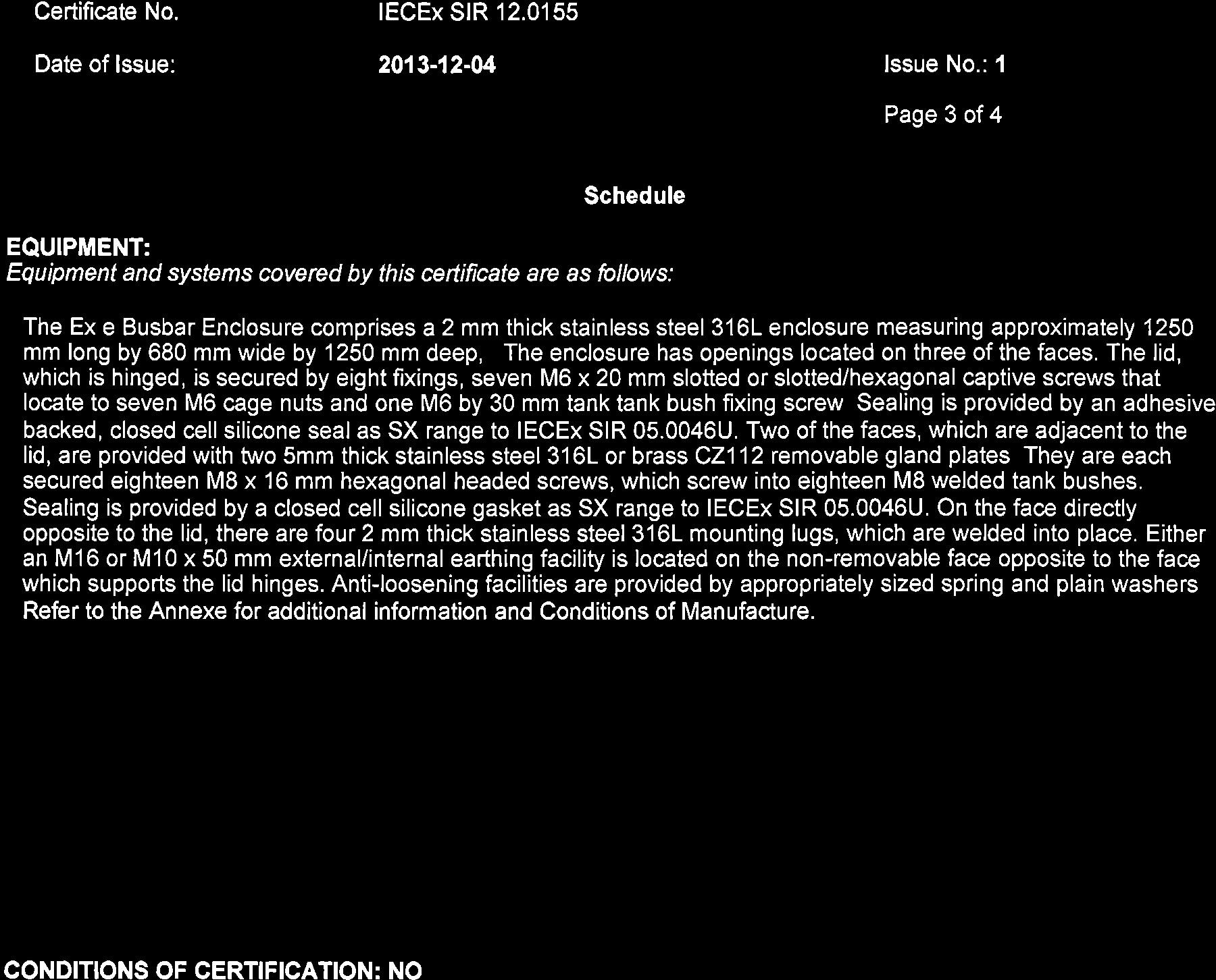
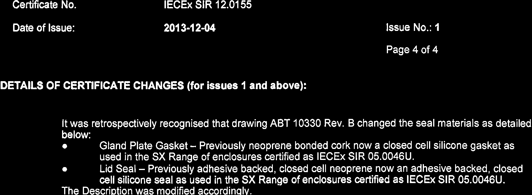
 IECEx Certificate of Conformity INTERNATIONAL ELECTROTECHNICAL COMMISSION IEC Certification Scheme for Explosive Atmospheres for rules and details of the IECEx Scheme visit www.iecex.com Certificate No.:
Installation Instructions:
 Portable Guardrail System Model Numbers: 7900060, 7900061, 7900062, 7900063 Installation Instructions: Portable Guardrail System This instruction is intended to meet the Manufacturer s Instructions requirement
ELECTRIC METERING COMMERCIAL & INDUSTRIAL
 ELECTRIC METERING COMMERCIAL & 1.0 INDEX 1.0 INDEX 2.0 SCOPE 3.0 GENERAL REQUIREMENTS 4.0 METER LOCATIONS 5.0 UNDERGROUND TERMINATIONS 6.0 METERING TRANSFORMER ENCLOSURES 7.0 SINGLE CUSTOMER METER INSTALLATIONS
WE-350 Series ¼ Turn Electric Actuator
 WE-350 Series ¼ Turn Electric Actuator Operation and Installation Manual Pg 1 (Rev. 020113) Table of Contents 1.0 General 1.1 Pre-Installation Inspection 1.2 Storage 1.3 Features & General Information
20000068 WIRELESS REMOTE ASSEMBLY, 24VDC, 1 TRANS,1 REC
 20000068 WIRELESS REMOTE ASSEMBLY, 24VDC, 1 TRANS,1 REC Fitment to MP-25 620 CR 4841, Haslet, TX 76052 Ph 817.439.1108 Fax 817.636.5675 www.machine-technologies.com Kit contents 1 Transmitter 2 button,
Directory chapter 02 - DIN Power (to 6 A) Types D, E, F, FM, 2F, F9, interface connectors I/U 02. 01. Technical characteristics types D and E... 02.
 Types D, E, F, FM, 2F, F9, interface connectors I/U 02. 01. Technical characteristics types D and E... 02.") Directory chapter 02 - () Types D, E, F, FM, 2F, F9, interface connectors I/U Page Technical characteristics types D and E.............................. 02.10 Type D connectors.................... 02.11
Directory chapter 02 - () Types D, E, F, FM, 2F, F9, interface connectors I/U Page Technical characteristics types D and E.............................. 02.10 Type D connectors.................... 02.11
Assembly Instruction CAI- Connector with universal Endbell
 CANNON STANDARD Seite 1 von 17 CAI- Connector with universal Endbell Shell size 10 to 36 with APK contact / Trident T2P - contact Illustration and assembly exemplary of CAI Layout 20-0306 with APK / Trident
VW Caddy W21-760-3503 INSTALLATION INSTRUCTIONS
 Unit 626 Kilshane Avenue, North West Business Park, Ballycoolin, Dublin 15, Ireland Telephone: +353 1 8612 632, Fax: +353 1 8612 647, email: sales@driveriteltd.com www.driveriteltd.com VW Caddy W21-760-3503
EXPLOSION-PROOF EMERGENCY LIGHTING FIXTURE FOR FLUORESCENT LAMP EVF-..-EL SERIES
 EXPLOSION-PROOF EMERGENCY LIGHTING FIXTURE FOR FLUORESCENT LAMP EVF-..-EL SERIES Gas explosion protection II 2G Ex d IIC T6 Gb (suitable for Zone1 and Zone 2) Dust explosion protection II 2D Ex tb IIIC
33.6W Power over Ethernet Waterproof Adapter PoE Plus Single Port Injector for Outdoor Application
 33.6W Power over Ethernet Waterproof Adapter PoE Plus Single Port Injector for Outdoor Application Features Compliant with the IEEE802.3at Standard -40 to +60 C Temperature Range Diagnostic LEDs Full Protection
STB Series Enclosures
 STB Series Enclosures Features/Applications: The STB series of sheet steel enclosures are designed to meet the requirement for distribution and lighting junction boxes. Available in 14 sizes with standard
Triac Printed Circuit Board Replacement
 Technical Service Bulletin: Triac Printed Circuit Board Replacement TRONIC 5000C Pro Models: WH17, WH27, WH36 Introduction Fig. 1 ELECTRICITY IS EXTREMELY DANGEROUS. TAKE EXTRA PRECAUTIONS AND ENSURE ALL
Unified requirements for systems with voltages above 1 kv up to 15 kv
 (1991) (Rev.1 May 2001) (Rev.2 July 2003) (Rev.3 Feb 2015) Unified requirements for systems with voltages above 1 kv up to 15 kv 1. General 1.1 Field of application The following requirements apply to
3.1.1 Full Type Tests & Routine Tests according to Clause 8 2 & 8 3. 4.0 Instructions For Installation, Operation & Maintenance
 SPECIFICATION FOR LOW VOLTAGE SWITCHBOARD SEN I N D E X Description 10 STANDARD TECHNICAL REQUIREMENTS 11 Standards 12 General Operating Conditions 13 General Description Of Switchboard 131 Structure 132
Sealed Industrial Ethernet Circular IP67 Cat. 5e RJ45 Connector System
 Revised Sept--22-2009 Sealed Industrial Ethernet Circular IP67 Cat. 5e RJ45 Connector System Description The sealed circular RJ45 connector system is designed for use in harsh environments. The connector
JANUS INTERNATIONAL CORPORATION INSTALLATION INSTRUCTIONS Pantheon Mini Operator
 JANUS INTERNATIONAL CORPORATION INSTALLATION INSTRUCTIONS Pantheon Mini Operator The Janus Pantheon mini operator does not typically require the provision of any additional site requirements other than
OVEN PARTS For Models:GSC308PJB05, GSC308PJQ05, GSC308PJT05, GSC308PJS05 (Black) (White) (Biscuit) (Black Stainless)
 (White) (Biscuit) (Black Stainless)") OVEN PARTS 30" BUILT IN ELECTRIC COMBO SENSOR/SC (GOLD LINE) 3 05 Litho In U.S.A. (cre) 1 Part No. Rev.A OVEN PARTS 1 Literature Parts 4455994 Installation Instructions Use & Care Guide 8300346 Microwave
OVEN PARTS 30" BUILT IN ELECTRIC COMBO SENSOR/SC (GOLD LINE) 3 05 Litho In U.S.A. (cre) 1 Part No. Rev.A OVEN PARTS 1 Literature Parts 4455994 Installation Instructions Use & Care Guide 8300346 Microwave
Awning Instructions. Full Cassette 1.5m to 6m
 Awning Instructions Full Cassette 1.5m to 6m English Full Cassette Manual & Electric Instructions Contents Warning 1.5m - 3.5m Awnings 8 x Expansion bolts ** 2 x brackets 1 x Awning 1 x Winder 4.0m -
RAY-MAX Integrated Solar Power Strip
 RAY-MAX Integrated Solar Power Strip 600008, 600009, 600010, 600208, 600209, 600210 Owner s Manual NEXTRONEX, INC. Revision Date: 10/27/14 Contents 1. Safety Instructions... 3 2. General Equipment Warnings...
Outdoor 33.6W Dual Port Passive Power-over-Ethernet Midspan For External Security Cameras and Wireless Access Points
 Outdoor 33.6W Dual Port Passive Power-over-Ethernet Midspan For External Security Cameras and Wireless Access Points Features SELV Compliant No Detection Passive Injector Gigabit Compatible Full Protection
Signaling Lights. LH Series Surface Mount Indicators. Part Numbers. Jumbo Dome (one color) Jumbo Dome (two color)
 Jumbo Dome (two color)") Innovative indicators in a slim & stylish design. uces installation space. LH Series Surface Mount Indicators Key features of the LH series include: Direct mounting on surfaces such as panels, aluminum
Innovative indicators in a slim & stylish design. uces installation space. LH Series Surface Mount Indicators Key features of the LH series include: Direct mounting on surfaces such as panels, aluminum
Rosemount 5300 and 5400 Series Terminal Compartment Spare Part Instruction
 Manual Supplement Rosemount 5300 and 5400 Series Rosemount 5300 and 5400 Series Terminal Compartment Spare Part Instruction Introduction..................................... page S-1 Safety Messages.................................
Table of Contents. Overview 1. Pump Disassembly 2. Control Disassembly / Reassembly 7. Pump Reassembly 13. Adjustment Procedures DR Control 19
 Table of Contents Overview 1 Pump Disassembly 2 Control Disassembly / Reassembly 7 Pump Reassembly 13 Adjustment Procedures DR Control 19 Adjustment Procedures DRG Control 20 Adjustment Procedures DFR
Technical Information
 Technical Information This section of the catalogue provides technical information that will help specify, install and maintain Surelock McGill devices and components. The topics are listed below: Blast
Installation Instructions DTS-HAZ DTS-HAZ-DC. for Use with Self-Regulating & Constant Wattage Heating Cables
 Installation Instructions DTS-HAZ DTS-HAZ-DC for Use with Self-Regulating & Constant Wattage Heating Cables PJ944-9 5625-81049 May 2013 1 2 DTS-HAZ Self-Regulating & Constant Wattage Heating Cables Junction
INSTALLATION INSTRUCTIONS MULTI-MOUNT KIT Part Number: 75330 Application: Warn HP PowerPlant P/N 71800
 INSTALLATION INSTRUCTIONS MULTI-MOUNT KIT Part Number: 75330 Application: Warn HP PowerPlant P/N 71800 Your safety, and the safety of others, is very important. To help you make informed decisions about
LSA-PLUS Series 2 Connection and Disconnection Modules and Accessories
 LSA-PLUS Series 2 Connection and Disconnection Modules and Accessories 2015 PRODUCT CATALOG 2ND EDITION LSA-PLUS Series 2 Connection and Disconnection Modules and Accessories A technically and commercially
IntelliChlor Flow-Temperature Switch Replacement Kit Installation Guide
 IntelliChlor Flow-Temperature Switch Replacement Kit Installation Guide Technical Support Sanford, North Carolina (8 A.M. to 5 P.M.) Moorpark, California (8 A.M. to 5 P.M.) Phone: (800) 831-7133 Fax: (800)
MUSTANG II IFS COMPLETE PARTS PACKAGE
 MUSTANG II IFS COMPLETE PARTS PACKAGE Your Southern Rods & Parts Mustang II IFS Parts Package contains the following items: 1 pr) Upper Control Arms (2023) 1) Upper Arm Bolt Kit (MP-001-A) 1 pr) Lower
Char-Lynn Hydraulic Motor. Repair Information. 10 000 Series. October, 1997
 Char-Lynn Hydraulic Motor October, 1997 Repair Information Geroler Motor Two Speed 001 27 Retainer inside bore of valve plate bearingless motors only 4 15 16 3 6 35 Parts Drawing 25 2 2 1 19 17 36 40 47
2 & 5-Wire Overfill Sensors
 2 & 5-Wire Overfill Sensors Optic overfill sensors detect the presence of liquid at a preset level. The new Civacon Universal 2 & 5-Wire Sensor is fully compatible with all our current Sensors and Monitors,
Installation Instructions 6028.801
 DAZZLE Installation Instructions 08.80 Spread Lavatory Faucet with Speed Connect Drain* Congratulations on purchasing your American Standard faucet with Speed Connect drain, a feature found only on American
Precision Miniature Load Cell. Models 8431, 8432 with Overload Protection
 w Technical Product Information Precision Miniature Load Cell with Overload Protection 1. Introduction The load cells in the model 8431 and 8432 series are primarily designed for the measurement of force
SERVICE SERVICE COMPACT MANUAL. Mod. 3000 92X Mod. 3000 93X Mod. 3000 94X. Part 2
 SERVICE COMPACT SERVICE 000 MANUAL Mod. 000 9X Mod. 000 9X Mod. 000 94X Part Forward This Service Handbook is intended to assist with servicing and fault-finding in Caravans and Motor Caravans equipped
BUILT-IN DISHWASHER INSTALLATION INSTRUCTIONS
 BUILT-IN DISHWASHER INSTALLATION INSTRUCTIONS PLEASE READ COMPLETE INSTRUCTIONS BEFORE YOU BEGIN LEAVE INSTALLATION INSTRUCTIONS AND USER'S GUIDE WITH OWNER ALL ELECTRIC WIRING AND PLUMBING MUST BE DONE
DirectCommand Installation DirectCommand 3-Channel Spreader Kit
 Note: Indented items indicate parts included in an assembly listed above Part Name/Description Part Number With Switch Box Quantity With Remote Switch Display Cable Kit 4100814 1 1 Power Control Relay
Machine devices, jig devices
 Machine devices, jig devices 853 K0697 Rolled thread studs DIN 6379 Material: Tempered steel. KIPP Rolled thread studs DIN 6379 Order No. D L B1 B2 Approx. weight g Surface finish: Thread rolled. Class
Trillium 40 Axis Spring Tensioner Wire Replacement Instructions
 Trillium 40 Axis Spring Tensioner Wire Replacement Instructions 1 Overview The objective is to replace the broken axis spring tensioner wire. This requires the following tasks: 1. Remove the seismometer
SIMRAD SD10 Sailboat Drive
 INSTALLATION MANUAL SIMRAD SD10 Sailboat Drive 20222683/A English Simrad SD10 Sailboat Drive About this document Rev. A First issue 2007 Navico AS. All rights reserved. No part of this work covered by
POSEIDON 2-29, 2-25 & 2-22 POSEIDON 2-29, 2-25 & 2-22 XT
 POSEION 2-29, 2-25 & 2-22 POSEION 2-29, 2-25 & 2-22 XT Repair Manual Index A. Safety precautions 3 B. Technical data 4 C. Structure 5-6. Service / Repair 7-23 E. Tools 24 F. Function 25-26 G. Electric
PowerLine. Single Pole Connectors
 PowerLine Single Pole Connectors Ten 47 Limited Unit 2B Frances Industrial Park Kirkcaldy, Scotland, UK KY1 2XZ Tel: +44 (0)1592 655725 Fax: +44 (0)1592 651049 Email: sales@ten47.com INTRODUCTION BACKGROUND
RMM2 Heat-Tracing Remote Monitoring Module for the Raychem NGC Control System Installation Instructions
 Heat-Tracing Remote Monitoring Module for the NGC Control System Installation Instructions Tools Required 3 mm slotted screwdriver 3/8 hex key (for -4X only) Approvals Nonhazardous locations Type NM LISTED