Study about the rapid manufacturing of complex parts of stainless steel and titanium
|
|
|
- Griffin Brown
- 7 years ago
- Views:
Transcription
 Laura Castillo Copy no. No. of copies Number of pages Number of appendices Customer Projectname Projectnumber All rights reserved.")
1 TNO report with the collaboration of AIMME Study about the rapid manufacturing of complex parts of stainless steel and titanium Date November 16, 2005 Author(s) Laura Castillo Copy no. No. of copies Number of pages Number of appendices Customer Projectname Projectnumber All rights reserved. No part of this publication may be reproduced and/or published by print, photoprint, microfilm or any other means without the previous written consent of TNO. In case this report was drafted on instructions, the rights and obligations of contracting parties are subject to either the Standard Conditions for Research Instructions given to TNO, or the relevant agreement concluded between the contracting parties. Submitting the report for inspection to parties who have a direct interest is permitted TNO
2 2 / 31 Contents 1 Introduction Technologies D Printing. ProMetal Selective Laser Melting. (SLM) MCP Laser Forming.Trumpf LaserCusing. Concept Laser Benchmark model Overhang Warpage Building angles Wall thickness Critical geometries: narrow and high details Critical geometries: small through holes and Z- bonus Critical geometries: curved areas Mechanical properties Analysis and results Building parameters and general observations Dimensional accuracy Building time Mechanical properties Conclusions Literature... 31
3 3 / 31 1 Introduction Rapid manufacturing is the use of additive fabrication technology to directly produce useable products or parts. Geometric freedom, use of multiple materials, elimination of tooling, mass customization and lowered costs are some of the advantages of these processes. However a great accuracy, good mechanical properties and low prototype time[i1] are needed to be a competitive manufacturing process. Since the origin of rapid manufacturing as an evolution of rapid prototyping many companies are developing processes and materials in this direction and applications fields are increasing as soon as new improvements are being reached. Technology is advancing so fast that an updated of the state of the art is necessary. The objective of this project is to test available and under development technologies for the rapid manufacturing of complex metal parts in order to know the currently state of the art Getting to know advantages and limitations of these processes will make it possible to find potential manufacturing applications and to select the most suitable process for any customer needs. For the performance of [I2]this project, several companies on different technologies will be asked to build the same part in metal as benchmarking. Parts will be built in steel or titanium alloys. Steel was the first commercially available material from many companies due its main application as rapid tooling, while titanium in many cases is still under development Accuracy, detail capability and geometry limitations will be measured to test the quality of the parts. Tensile and hardness test will be performed on building materials to determine mechanical properties. Building time will be considered as the total amount of machine hours and secondary operations. Post processing like support removal and finishing processes will not be taken into account.


4 4 / 31 2 Technologies 2.1 3D Printing. ProMetal The ProMetal 3D printing process is an indirect technology, which consists in jetting a binder onto a metal powder bed. Parts are built up layer by layer to near net shape. Upon completion, the green part is loaded into a sintering furnace that fuses the tool steel powder into a form that has 60 percent density, while burning off the binder. In a second furnace cycle, this porous structure is infiltrated with molten bronze via capillary action to reach full density. Figure 1 Courtesy of ProMetal 2.2 Selective Laser Melting. (SLM) MCP SLM is a direct process based on a principle in such manner that the powder is applied in very thin layers on a building platform and melted due to the thermal influence of a laser beam. In each layer the laser beam generates the outline of the part that is being built by melting the powder particles, before the building platform is lowered and coated with a new layer of powder Figure 2 Courtesy of MCP


5 5 / Laser Forming. Trumpf In this process, like in MCP, the laser beam melts on the powder layer. Adjacent melting traces and stacked layers are welded together and the build platform is lowered by the set layer thickness. These steps are repeated until the entire component is complete. Figure 3 Courtesy of Trumpf 2.4 LaserCusing. Concept Laser Like the previous direct processes, this method fused layer for layer single component metallic powder to produce an almost 100% component density. A patented exposure strategy allows the generation of solid and large-volume components without any deformation. A special surface post-treatment process, called micro blasting, directly after the construction process ensures the highest surface quality and hardness. Figure 4 Courtesy of Concept laser GmbH


6 6 / 31 3 Benchmark model This picture shows a 60*100*81 mm part which has been designed specifically to study the following features: Figure 5 Benchmark model 3.1 Overhang Many technologies have difficulties in building an overhang plane due to the process definition of layered wise production in a powder bed. Some of the processes can solve this problem by using support structures, which afterwards have to be removed by post machining. This solution will increase production time and the need of secondary operations. The benchmark part has been designed with a table shape whereby the overhang plane at the interior side is a building challenge. Figure 6 Overhang plane


7 7 / 31 Warpage Warpage is the excessive distortional change in a processed part after it has been removed out of the powder bed at the end of the process. The term warpage is employed when a whole part is being bowed. The main cause for warpage is inhomogeneous shrinkage. Both shrinkage and warpage will depend on the material properties, part geometry and process conditions. Wall thickness transitions also exert influence on the heat transfer within a part. To evaluate this phenomenon the part has been designed with a table shape where there is a wall thickness transition from 10 to 5 mm. Figure 7 "Table" shape 3.2 Building angles Due layers construction some technologies have difficulties in building features with a specific angle. In some of them supports may be needed. To study this capability an open book shape has been designed. The sheets are placed in angles of 0, 15, 30, 45, 60, 75 and 90 degrees. Figure 8 "Open book" shape


8 8 / Wall thickness Laser spot limits usually minimal wall thickness. In this part, elements with 2, 1 and 0.5 mm wall thickness have been designed to study this limitation. The open book s sheets have a 2 mm wall thickness and the two first circular and square towers have been designed hollow with 1 and 0.5 mm thickness. 3.4 Critical geometries: narrow and high details There is a risk that the internal stresses will induce cracks where there are layer defects in high parts. Square and circular towers with heights of 30, 20, 10, 5 and 2.5 mm and different dimensions or diameters have been designed to analyze the risk of cracking. There are also towers with 1 and 0.5 mm diameter, which in some cases, may not be built due to minimal spot laser. Figure 9 High and narrow details 3.5 Critical geometries: small through holes and Z- bonus. In layer production technologies, part orientation is a very important building factor. Building features in XY plane is[i3] easier than making then in XZ or YZ plane due to layer slicing in Z direction. In some cases surfaces will become thicker than planned. On the other hand, small holes may not be built due to minimal spot laser. To test detail capability through holes of 4, 3, 2, 1, and 0.5 mm diameter and 10 mm length have been placed at the top plane (XY). At the right and left plane (YZ) holes of 10, 4, 3, 2, and 1 mm with 5 mm length can be found. At the front plane (XZ) there is a through hole of 8 mm diameter and 100 mm length. Figure 10 Holes in different directions
9 9 / Critical geometries: curved areas For layers production technologies it may be difficult to build curved areas due to layer slicing. Two elliptical areas with different dimensions have been placed at the top plane (XY) to test this capability. Figure 11 Curved areas 3.7 Mechanical properties Some of the open book s sheets will be used to obtain specimens for a tensile and hardness test to determine mechanical properties.
10 10 / 31 4 Analysis and results 4.1 Building parameters and general observations Due to the complex design of the benchmark model, it has been very difficult to find companies, which accepted this building challenge. Following technologies and materials have participated in the study. Steel Alloy Technology Equipment Company Alloy Name LaserCusing Selective Laser Melting M3 Linear MCP Realizer SLM Concept Laser GmbH MCP Tooling Technologies LTD 3DP Printing R2 ProMetal CL 20ES AISI 316L Stainless Steel / DIN 1,4404 S4 (60% Stainless steel + 40% bronze) Similar to commercial alloy AISI 316L Stainless Steel / DIN 1,4404 AISI 420 Stainless steel / DIN Titanium Alloy Technology Equipment Company Alloy Name Laserforming Trumaform 250 Trumpf TiAl 6 V4 Similar to commercial alloy

 Layer")


11 11 / 31 ProMetal For the benchmark model the following build parameters were used: Material: S4 (60% Stainless/ 40% Bronze) Layer thickness: 100 µm. 616 layers. Mode: printed 1 way Due to the ProMetal process it was necessary to add a support for bronze infiltration. This support will be machined before testing. Figure 12 ProMetal part with supports Figure 13 Left and right plane Figure 14 Back and top plane


12 12 / 31 Overhang, angle planes and logo were positive built without supports, but some features like the small holes and cylinders were missing at the top plane. Small through holes were positive built at right and left plane but not at front plane. Figure 15 ProMetal benchmark features Figure 16 Logo and through holes at right plane


13 13 / 31 MCP For the benchmark model following build parameters were used: Material: Stainless Steel 316L Layer thickness: 75 µm MCP had to add supports to build overhang, trough holes, logo and angle planes below 45 degrees. The part also needs to be removed from the building platform. Figure 17 MCP part with supports at left and front plane Figure 18 Right and back plane Figure 19 Top plane


14 14 / 31 The effect of Z-bonus and warpage is remarkable[i4] at front plane Figure 20 Warpage and Z-bonus All features at top plane were positive built. Figure 21 MCP benchmark features


15 15 / 31 Concept Laser For the benchmark model following build parameters were used: Material: Stainless Steel 316L Layer thickness: 30 µm Finishing process: Micro blasting Concept Laser built the part rotated over 135 degrees and used supports which were removed after building. Figure 22 Concept Laser building orientation Due this building orientation, warpage and Z-bonus cannot be studied. In some critical geometries the effects of the supports can be noticed due this building orientation. There is also a deviation from the vertical plane in the angle plane supposed to be built at 90 degrees, in one of the book s sheets. Figure 23Effects of the building orientation


16 16 / 31 It was also necessary to add a support structure to the file to build the overhang plane. Holes were made to reduce support-building time. Due this added support, holes are not through. Through holes at front plane were positive built. Figure 24 Concept Laser part with support Figure 25 Right and back plane Logo and all details at top plane were positive built. Figure 26 Concept Laser benchmark features


17 17 / 31 Trumpf For the benchmark model following build parameters were used: Material: TiAl 6 V4 Layer thickness: 50 µm Trumpf had to add supports to build overhang, trough holes and angle planes below 45 degrees. No supports were needed to build the logo. Figure 27 Trumpf benchmark model with supports Figure 28 Right and back plane Figure 29 Top and bottom plane


18 18 / 31 There is a thickness defect at angle planes and warpage at front and back plane. Figure 30 Thickness defect and warpage Logo and most of the critical geometries at top plane were positive built but some geometries like tetrahedrons were missing. Figure 31 Benchmark details
19 19 / Dimensional accuracy Testing procedure A digital calliper was used to test accuracy. All dimensions were averaged after five times measurements. Each critical dimension has been analysed separately and compare between technologies. Parts have been scanned and compared with the stl file. A table with the deviation average and standard deviation by company is included at the end of this study. Main dimensions Figure 32 Main dimensions Nominal Values ProMetal MCP Concept Laser Trumpf A ,60 0,40 100,04-0,04 99,99 0,01 99,68 0,32 B 60 59,89 0,11 60,06-0,06 60,09-0,09 61,40-1,40 C 81 80,91 0,09 80,23 0,77 80,99 0,01 80,13 0,87 D 25 25,40-0,40 24,71 0,29 25,04-0,04 24,92 0,08 E 10 10,27-0,27 9,90 0,10 10,10-0,10 F 5 5,25-0,25 5,20-0,20 5,32-0,32
20 20 / 31 Main dimensions 1,50 1,00 Deviation 0,50 0,00-0, Prometal MCP Concept Laser Trumpf -1,00-1,50 Nominal Values Tetrahedrons Tetrahedrons 2,00 1,50 1,00 Deviation 0,50 0,00-0, Prometal MCP Concept laser Trumpf -1,00-1,50-2,00 Nominal values Figure 33 Tetrahedrons
21 21 / 31 Nominal Values ProMetal MCP Concept laser Trumpf L1 5 5,60-0,60 5,21-0,21 5,17-0,17 5,40-0,40 W1 5 5,70-0,70 5,15-0,15 5,28-0,28 5,42-0,42 T1 1 1,80-0,80 1,10-0,10 1,27-0,27 1,40-0,40 I ,80 0,20 30,12-0,12 29,96 0,04 30,17-0,17 L2 4 5,08-1,08 4,18-0,18 4,20-0,20 4,32-0,32 W2 4 4,85-0,85 4,15-0,15 4,20-0,20 4,30-0,30 T2 1 1,70-1,20 0,60-0,10 0,75-0,25 0,85-0,35 I ,40-0,40 20,20-0,20 20,01-0,01 20,01-0,01 L3 2 3,41-1,41 2,08-0,08 2,20-0,20 2,41-0,41 W3 2 3,60-1,60 2,05-0,05 2,20-0,20 2,39-0,39 I ,40-0,40 10,14-0,14 10,01-0,01 10,20-0,20 L4 1 1,70-0,70 1,05-0,05 1,23-0,23 1,35-0,35 W4 1 1,90-0,90 1,04-0,04 1,25-0,25 1,27-0,27 I4 5 5,50-0,50 4,98 0,02 4,94 0,06 5,12-0,12 L5 1 0,90-0,40 0,60-0,10 0,77-0,27 W5 1 0,78-0,28 0,55-0,05 0,77-0,27 I5 3 2,60-0,10 2,62-0,12 2,56-0,06 Cylinders Cylinders 0,50 0,40 0,30 0,20 Deviation 0,10 0,00-0,10-0,20-0,30-0,40-0, Nominal values Prometal MCP Concept laser Trumpf Figure 34 Cylinders
22 22 / 31 Nominal Values ProMetal MCP Concept laser Trumpf D1 5 5,25-0,25 5,10-0,10 5,20-0,20 5,30-0,30 C1 1 1,30-0,30 1,15-0,15 1,30-0,30 1,40-0,40 H ,81 0,19 30,01-0,01 30,04-0,04 29,89 0,11 D2 4 4,20-0,20 4,15-0,15 4,18-0,18 4,27-0,27 C2 0,5 0,85-0,35 0,60-0,10 0,88-0,38 0,90-0,40 H ,92 0,08 20,02-0,02 20,06-0,06 19,97 0,03 D3 2 2,04-0,04 2,16-0,16 2,23-0,23 H ,01-0,01 10,08-0,08 9,98 0,02 D4 1 1,28-0,28 1,02-0,02 1,20-0,20 1,15-0,15 H4 5 4,92 0,08 5,08-0,08 4,99 0,01 D5 0,5 0,58-0,08 0,70-0,20 H5 2,5 2,45 0,05 2,49 0,01 Angles Figure 35 Angles Nominal Values ProMetal MCP Concept Laser Trumpf A1 0 0,21-0,21 0,16-0,16 0,09-0,09 0,21-0,21 A ,44-0,44 14,20 0,80 14,97 0,03 15,62-0,62 A ,31-0,31 29,90 0,10 29,97 0,03 30,3-0,30 A ,51-0,51 44,90 0,10 44,85 0,15 45,47-0,47 A ,09-1,09 59,60 0,40 59,93 0,07 59,87 0,13 A ,79-1,79 74,80 0,20 74,93 0,07 74,95 0,05 A ,19-1,19 89,43 0,57 88,58 1,42 89,73 0,27
23 23 / 31 Angles 2,00 1,50 1,00 Deviation 0,50 0,00-0,50-1, Prometal MCP Concept laser Trumpf -1,50-2,00 Nominal values Thickness Thickness 0,50 0,40 0,30 Deviation 0,20 0,10 0,00-0,10-0,20 PROMETAL MCP CONCEPT LASER Trumpf -0,30-0,40-0,50 Nominal value Nominal Values PROMETAL MCP CONCEPT LASER Trumpf S1 2 2,06-0,06 1,96 0,04 2,05-0,05 2,11-0,11 S2 2 2,5-0,50 1,91 0,09 2,2-0,20 2,32-0,32 S3 2 2,4-0,40 2,2-0,20 2,28-0,28 2,42-0,42 S4 2 2,5-0,50 2,12-0,12 2,25-0,25 2,22-0,22 S5 2 2,4-0,40 2,07-0,07 2,21-0,21 2,28-0,28 S6 2 2,3-0,30 2,06-0,06 2,23-0,23 2,36-0,36 S7 2 2,25-0,25 2,05-0,05 2,22-0,22 2,37-0,37
24 24 / 31 Holes Holes 0,50 0,40 0,30 Deviation 0,20 0,10 0,00-0,10-0, Prometal MCP Concept Laser Trumpf -0,30-0,40-0,50 Nominal Values Holes XY (top) YZ (right) YZ (left) Nominal Values ProMetal MCP Concept Laser Trumpf B1 4 3,81 0,19 3,83 0,17 3,84 0,16 3,87 0,13 B2 3 2,77 0,23 2,91 0,09 2,828 0,17 2,85 0,15 B3 2 1,74 0,26 1,91 0,09 1,869 0,13 1,68 0,32 B4 1 0,76 0,24 0,949 0,05 0,836 0,16 B5 0,5 0,498 0,00 0,4 0,10 R1 10 9,89 0,11 9,85 0,15 9,987 0,01 9,5 0,50 R2 4 3,88 0,12 3,93 0,07 3,81 0,19 3,61 0,39 R3 3 2,96 0,04 2,73 0,27 2,76 0,24 2,66 0,34 R4 2 1,88 0,12 1,84 0,16 1,8 0,20 1,7 0,30 R5 1 0,98 0,02 0,83 0,17 0,81 0,19 0,67 0,33 E1 10 9,71 0,29 9,8 0,20 9,85 0,15 9,59 0,41 E2 4 3,67 0,33 3,88 0,12 3,76 0,24 3,71 0,29 E3 3 2,84 0,16 3,01-0,01 2,84 0,16 2,68 0,32 E4 2 1,79 0,21 1,81 0,19 1,82 0,18 1,79 0,21 E5 1 0,68 0,32 0,84 0,16 0,82 0,18 0,79 0,21 XZ F1 8 7,71 0,29 8,06-0,06 7,81 0,19 7,76 0,24


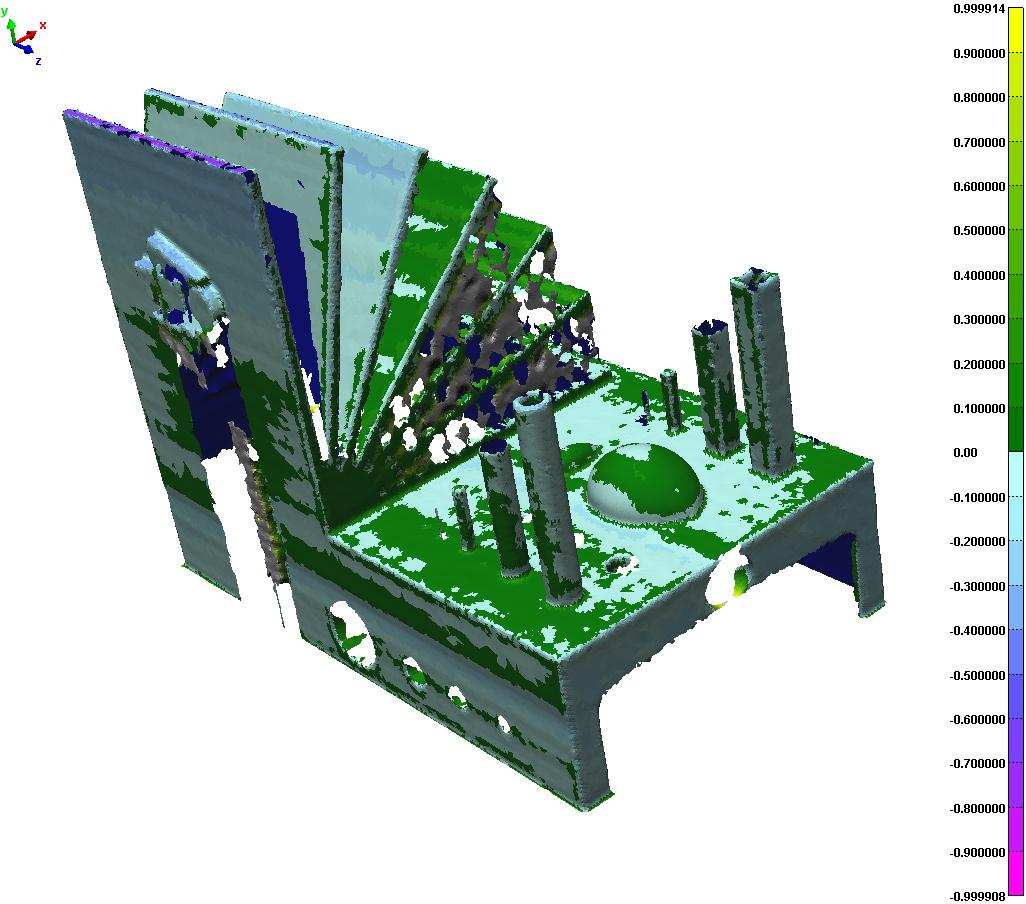
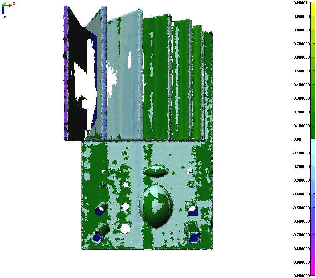
25 TNO and AIMME report Scan accuracy results ProMetal MCP 25 / 31


26 26 / 31 Concept Laser Trumpf: Average and standard deviation ProMetal MCP Concept Laser Trumpf Average Deviation 0,44 0,14 0,16 0,30 Standard Deviation 0,39 0,15 0,18 0,21
27 27 / Building time Building time was considered as the total amount of machine hours and secondary operations but no finishing processes. Time required to remove supports and part from the building platform has not been considered. Following values were provided by companies and have not been checked by the technicians of the project. Building time Time (h) ProMetal MCP Concept Laser Companies Trumpf Secondary operations Machine time Figure 36 Building time
28 28 / Mechanical properties Hardness test Hardness Vickers test was made according to UNE EN ISO /98 Equipment used was durometer: Wolper V-Testor 2 con I 0 = 8.2 HV 5 Tensile test According to the standard ISO 6892, specimens were prepared from cutting some of the book s sheets of the part, with the following dimensions. Figure 37 Tensile test piece drawing
29 29 / 31 Steel Alloy Technology Company Alloy Name Similar to commercial alloy: Hardness (Vickers) Conversion to Hardness (Rockwell C) Material data Sheet Hardness Tensile strength (MPa) Material Data Sheet Tensile strength (MPa) Elongation at Break Material Data Sheet Elongation at Break Laser Cusing Concept Laser Selective Laser Melting 3D Printing MCP ProMetal CL 20ES AISI 316L Stainless Steel / DIN 1,4404 Stainless steel + bronze AISI 316L Stainless Steel / DIN 1,4404 AISI 420 Stainless steel / DIN ,6 19,54 ( HRC ) 20 ( HRC ) 648, , ,4 237 (Vickers) 626, , ,8 23,25 ( HRC ) ( HRC ) 358, ,56 2,3 Titanium Alloy Technology Company Alloy Name Similar to commercial alloy: Hardness (Vickers) Material data Sheet Hardness Tensile strength (MPa) Material Data Sheet Tensile strength (MPa) Elongation at Break Material Data Sheet Elongation at Break Laser Forming Trumpf TiAl 6 V4 415,6 420 (Vickers) 1165, ,59 5,8-6,2
30 30 / 31 5 Conclusions Due to the complex design of the benchmark model, it has been very difficult to find companies, which accepted this building challenge. Therefore the effort of the companies, which have accepted this job, is very appreciated. In this report has been checked [I5]that it is possible to build complex parts in stainless steel and titanium, and advantages and limitations of the technologies studied can be extended to complex production parts. Excepted the ProMetal benchmark model built by 3DP printing technique, all models required supports for building. These supports structures are very difficult to be removed, especially in benchmark models built by Trumpf using Laserforming and MCP (Selective Laser Melting technique). In this case, it is also difficult to remove the MCP benchmark model from the platform. Concept Laser benchmark model was built in another orientation and the supports needed were removed by provider. The remaining supports can be machined without difficulty. Dimensional accuracy was very good in MCP and Concept laser benchmark models with the best average and standard deviation for MCP. However in this model, the Z- bonus effect, which means that holes are not round due to layer construction at Z-axis, and warpage is remarkable. There was also warpage in the Trumpf model. All critical geometries were positive built in MCP and Concept Laser models, and some of them were missing in Trumpf and ProMetal models. Building time was considered as the total amount of machine hours and secondary operations but no finishing processes. Time required to remove supports and parts from the building platform has not been considered. Building time values were provided by companies and have not been checked by the technicians of the project. To determine mechanical properties, tensile and hardness test have been performed on building materials. Tensile strength, elongation and hardness obtained have been compared with material data sheets provided by companies, reaching in most cases the expected values.
31 31 / 31 6 Literature Castle Island Co., Worldwide Guide to Rapid Prototyping, Arlington, MA CRIF Material Technologies. State of the art report, 2. Rapid Tooling and mould making. June 2003 K.W Dalgarno, R.D Goodridge Compression testing of layer manufactured metal parts: the RAPTIA compression benchmark. Rapid Prototyping Journal. Volume 10. Number pp T.A. Grimm Rapid Prototyping Benchmark: 3D Printers. October 2003 N. P. Karapatis, J.-P. S. Van Griethuysen, R. Glardon Direct Rapid Tooling: A Review of current research Laboratory For Production Management & Processes. ICAP. Mechanical Engineering Department. Swiss Federal Institute Of Technology W.P.M Kruf. Design for Rapid manufacturing Functional SLS parts. August 2005 J-P. Kruth, B. Vandenbroucke, J. Van Vaerenberght, P. Mercelis Benchmarking of different SLS/SLM processes as rapid manufacturing techniques M. Mahesh, Y.S Wong, J.Y.H. Fuh, H.T Loh Benchmarking for comparative evaluation of RP systems and processes. Rapid Prototyping Journal. Volume 10. Number pp A.M Ramos, C. Relvas, J.A Simoes Vacuum casting with room temperature vulcanizing rubber and aluminium moulds for rapid manufacturing of quality parts: a comparative study. Rapid Prototyping Journal. Volume 9. Number pp M. Shellabear. Benchmark study of accuracy and surface quality in RP Models. RAPTEC., Task 4.2, Report 2. June 1999 M.Shellabear Model manufacturing processes-state of the art in rapid prototyping. RAPTEC, Task 4.2 Report 1. February 1998 T.Wholers Wholers Report 2005
BENCHMARKING OF DIFFERENT SLS/SLM PROCESSES AS RAPID MANUFACTURING TECHNIQUES
 Benchmarking of different SLS/SLM es as rapid manufacturing techniques BENCHMARKING OF DIFFERENT SLS/SLM PROCESSES AS RAPID MANUFACTURING TECHNIQUES J.-P. Kruth, B. Vandenbroucke, J. Van Vaerenbergh, P.
Chapter 5 POWDER-BASED RAPID PROTOTYPING SYSTEMS
 Chapter 5 POWDER-BASED RAPID PROTOTYPING SYSTEMS 5.1 3D SYSTEMS SELECTIVE LASER SINTERING (SLS) 5.1.1 Company 3D Systems Corporation was founded by Charles W. Hull and Raymond S. Freed in 1986. The founding
Rapid Prototyping. Training Objective
 Training Objective After watching the program and reviewing this printed material, the viewer will understand the principles and practical applications of Rapid Prototyping. Basic concepts are explained
Material data sheet. EOS StainlessSteel GP1 for EOSINT M 270. Description, application
 EOS StainlessSteel GP1 for EOSINT M 270 A number of different materials are available for use with EOSINT M systems, offering a broad range of e-manufacturing applications. EOS StainlessSteel GP1 is a
* This work is an official contribution of the National Institute of Standards and Technology and
 Variability in the Geometric Accuracy of Additively Manufactured Test Parts A.L. Cooke and J.A. Soons National Institute of Standards and Technology * Gaithersburg, MD, USA Abstract This paper describes
Material data sheet. EOS Aluminium AlSi10Mg. Description
 EOS Aluminium AlSi10Mg EOS Aluminium AlSi10Mg is an aluminium alloy in fine powder form which has been specially optimised for processing on EOSINT M systems This document provides information and data
Material data sheet. EOS CobaltChrome MP1. Description
 EOS CobaltChrome MP1 EOS CobaltChrome MP1 is a cobalt-chrome-molybdenum-based superalloy powder which has been optimized especially for processing on EOSINT M systems. This document provides information
The creation of tooling using the selective laser sintering process. Scott Schermer S.C. Johnson
 The creation of tooling using the selective laser sintering process Scott Schermer S.C. Johnson 1 TOOLING utilizing traditional rapid prototyping machines to produce metal inserts. 2 LaserForm ST-100?
Holes & Selective Laser Sintering
 SLS is one of the most accurate 3D printing processes. The process has a layer thickness of 0.1mm. This is the thickness with which a new layer is added to each part. In any direction therefore the maximum
GLOBAL MANUFACTURING. ARAUJO, Anna Carla AUG, 2015 Mechanical Engineering Department POLI/COPPE/UFRJ
 GLOBAL MANUFACTURING ARAUJO, Anna Carla AUG, 2015 Mechanical Engineering Department POLI/COPPE/UFRJ Workpiece Presentation Powder Metallurgy and Additive Manufacturing [#7] Powder Metallurgy PM parts can
Material data sheet. EOS MaragingSteel MS1. Description
 EOS MaragingSteel MS1 EOS MaragingSteel MS1 is a steel powder which has been optimized especially for processing on EOSINT M systems. This document provides information and data for parts built using EOS
D-M-E MoldFusion 3D Metal Printing. Mold tooling technology for complex applications conformal cooling, rapid tooling and beyond
 D-M-E MoldFusion 3D Metal Printing Mold tooling technology for complex applications conformal cooling, rapid tooling and beyond PAGE 61 Build The Unmachineable You ve seen it before the part demands cooling
Additive manufacturing (aka 3D printing) of metallic materials Industrial applications and efficiency of technology
 of metallic materials Industrial applications and efficiency of technology") Additive manufacturing (aka 3D printing) of metallic materials Industrial applications and efficiency of technology MANU Future digital manufacturing technologies and systems P6 Next Generation Manufacturing
Additive manufacturing (aka 3D printing) of metallic materials Industrial applications and efficiency of technology MANU Future digital manufacturing technologies and systems P6 Next Generation Manufacturing
RAPID PROTOTYPING. Learning Objectives: By the end of the lecture the student should be able to: Explain the fundamentals of Rapid Prototyping
 RAPID PROTOTYPING Learning Objectives: By the end of the lecture the student should be able to: Explain the fundamentals of Rapid Prototyping Outline and explain differences of Rapid Prototyping Technologies
Material data sheet. EOS Aluminium AlSi10Mg_200C. Description
 EOS Aluminium AlSi10Mg_200C All information in this data sheet refers to the alloy EOS Aluminium AlSi10Mg_200C. This alloy is formed when the powder EOS Aluminium AlSi10Mg is processes at a building platform
Outline of a quality system and standard for the certification of conformity
 Outline of a quality system and standard for the certification of conformity Although still in early steps, novel Additive Manufacturing (AM) processes are growing in expectations as enabling technology
How To Design A 3D Print In Metal
 DMLS / SLM Metal 3D Printing. An introductory design guide for our 3d printing in metal service. v2.2-8th July 2015 Pricing considerations. Part Volume. One of the biggest factors in the price for DMLS
Rapid prototyping. CAD / lecture. October 5, 2010. TO&I Vermelding onderdeel organisatie
 1 Rapid prototyping is: Rapid prototyping is an additive (layered) digital fabrication technology Layers of material are added forming the final 3d physical model The digital data of the virtual 3d model
Solid shape molding is not desired in injection molding due to following reasons.
 PLASTICS PART DESIGN and MOULDABILITY Injection molding is popular manufacturing method because of its high-speed production capability. Performance of plastics part is limited by its properties which
Additive Manufacturing: Processes and Standard Terminology
 Additive Manufacturing: Processes and Standard Terminology Gary Coykendall Copyright Edmonds Community College 2012; Permission granted for use and reproduction for educational purposes only. Abstract
Tool Design and Concurrent Engineering using Rapid Tooling Construction Methods
 Section Number 3563 Tool Design and Concurrent Engineering using Rapid Tooling Construction Methods Nicole Hoekstra Engineering Technology Department Western Washington University Abstract Prior to rapid
Unit 6: EXTRUSION. Difficult to form metals like stainless steels, nickel based alloys and high temperature metals can also be extruded.
 1 Unit 6: EXTRUSION Introduction: Extrusion is a metal working process in which cross section of metal is reduced by forcing the metal through a die orifice under high pressure. It is used to produce cylindrical
COMPARISON OF POLYJET PRINTING AND SILICON MOULDING AS RAPID PLASTIC MOULDING SOLUTIONS. R. Singh
 International Journal of Automotive and Mechanical Engineering (IJAME) ISSN: 2229-8649 (Print); ISSN: 2180-1606 (Online); Volume 6, pp. 777-784, July-December 2012 Universiti Malaysia Pahang DOI: http://dx.doi.org/10.15282/ijame.6.2012.9.0063
21. - 22. 11. 2012, Plzeň, Czech Republic, EU
 PRO-BEAM TECHNOLOGY - HEAT TREATMENT OF METALS Václav HOŠEK a, Filip VRÁBLÍK a, Uwe CLAUß b, Pavel STOLAŘ a a ECOSOND s.r.o., Čerčany, Czech Republic, EU, ecosond@ecosond.cz b pro-beam AG & Co.KgaA, Neukirchen,
Rapid Manufacturing of Dental Prostheses by means of Selective Laser Sintering/Melting
 Rapid Manufacturing of Dental Prostheses by means of Selective Laser Sintering/Melting J.-P. Kruth 1, B. Vandenbroucke 1, J. Van Vaerenbergh 1, I. Naert 2 1) K.U.Leuven, Dept. of Mechanical Engineering,
Sinterstation. Pro Direct Metal SLM System
 Sinterstation Pro Direct Metal SLM System Jim Dier SLS and SLM Systems, Upper Midwest 3D Systems, Inc. 18 July 2008 Introduction Product overview Systems Sinterstation Pro DM100 SLM System Sinterstation
Metal Injection Molded Parts
 Metal Injection Molded Parts Metal Injection Molding (MIM) is a powder metallurgy process. he difference between MIM and conventional powder metallurgy is that in MIM, metal powder along with binders is
Laser beam sintering of coatings and structures
 Laser beam sintering of coatings and structures Anne- Maria Reinecke, Peter Regenfuß, Maren Nieher, Sascha Klötzer, Robby Ebert, Horst Exner Laserinstitut Mittelsachsen e.v. an der Hochschule Mittweida,
ID@GT prepared by Gabe Landes for T. Purdy 2009
 Rapid prototyping is the automatic construction of physical objects using solid freeform fabrication. The first techniques for rapid prototyping became available in the late 1980s and were used to produce
NetShape - MIM. Metal Injection Molding Design Guide. NetShape Technologies - MIM Phone: 440-248-5456 31005 Solon Road FAX: 440-248-5807
 Metal Injection Molding Design Guide NetShape Technologies - MIM Phone: 440-248-5456 31005 Solon Road FAX: 440-248-5807 Solon, OH 44139 solutions@netshapetech.com 1 Frequently Asked Questions Page What
Assessing new support minimizing strategies for the additive manufacturing technology SLM. M. Cloots*, A.B. Spierings*, K. Wegener.
 Assessing new support minimizing strategies for the additive manufacturing technology SLM M. Cloots*, A.B. Spierings*, K. Wegener * Inspire-institute for rapid product development irpd, Lerchenfeldstrasse
VeMet, Utrecht, NL «Solution in Wear Protection» 26.10.2011 Dipl.-Ing. Wolfgang Leichnitz. Quit
 VeMet, Utrecht, NL «Solution in Wear Protection» 26.10.2011 Dipl.-Ing. Wolfgang Leichnitz Quit Theory and Practice of Wear Definition In materials science, wear is the erosion of material from a solid
Description of mechanical properties
 ArcelorMittal Europe Flat Products Description of mechanical properties Introduction Mechanical properties are governed by the basic concepts of elasticity, plasticity and toughness. Elasticity is the
Naue GmbH&Co.KG. Quality Control and. Quality Assurance. Manual. For Geomembranes
 Naue GmbH&Co.KG Quality Control and Quality Assurance Manual For Geomembranes July 2004 V.O TABLE OF CONTENTS 1. Introduction 2. Quality Assurance and Control 2.1 General 2.2 Quality management acc. to
As published in PIM International
 As published in PIM International www.pim-international.com 64 Powder Injection Moulding International September 2012 Rapid prototyping of highperformance ceramics opens new opportunities for the CIM industry
Fokus: PLAST Lund 4-5 maj Lunds Tekniske Högskola
 Fokus: PLAST Lund 4-5 maj Lunds Tekniske Högskola Production of injection moulds using AM technology - LaserCUSING Martin Nielsen, Product Manager Concept-Laser Agenda Who is Signcom Our Customers What
EXPERIMENTAL AND NUMERICAL ANALYSIS OF THE COLLAR PRODUCTION ON THE PIERCED FLAT SHEET METAL USING LASER FORMING PROCESS
 JOURNAL OF CURRENT RESEARCH IN SCIENCE (ISSN 2322-5009) CODEN (USA): JCRSDJ 2014, Vol. 2, No. 2, pp:277-284 Available at www.jcrs010.com ORIGINAL ARTICLE EXPERIMENTAL AND NUMERICAL ANALYSIS OF THE COLLAR
Numerical Analysis of Independent Wire Strand Core (IWSC) Wire Rope
 Wire Rope") Numerical Analysis of Independent Wire Strand Core (IWSC) Wire Rope Rakesh Sidharthan 1 Gnanavel B K 2 Assistant professor Mechanical, Department Professor, Mechanical Department, Gojan engineering college,
Numerical Analysis of Independent Wire Strand Core (IWSC) Wire Rope Rakesh Sidharthan 1 Gnanavel B K 2 Assistant professor Mechanical, Department Professor, Mechanical Department, Gojan engineering college,
Choosing optimal rapid manufacturing process for thin-walled products using expert algorithm
 Choosing optimal rapid manufacturing process for thin-walled products using expert algorithm Filip Górski, Wiesław Kuczko, Radosław Wichniarek, Adam Dudziak, Maciej Kowalski, Przemysław Zawadzki Poznan
TUTOR NOTES. How to use this pack. Rapid prototyping in schools. Definition
 TUTOR NOTES How to use this pack This pack is aimed at students studying for both Intermediate 2 and Higher Product Design. Students of other subjects might find it useful, and a Curriculum Map has been
DESIGN OF MANUFACTURING SYSTEMS BY RAPID PROTOTYPING TECHNOLOGY APPLICATION
 Annals of the University of Petroşani, Mechanical Engineering, 14 (2012), 104-111 104 DESIGN OF MANUFACTURING SYSTEMS BY RAPID PROTOTYPING TECHNOLOGY APPLICATION JOZEF NOVAK-MARCINCIN 1 Abstract: Rapid
4 Thermomechanical Analysis (TMA)
") 172 4 Thermomechanical Analysis 4 Thermomechanical Analysis (TMA) 4.1 Principles of TMA 4.1.1 Introduction A dilatometer is used to determine the linear thermal expansion of a solid as a function of temperature.
172 4 Thermomechanical Analysis 4 Thermomechanical Analysis (TMA) 4.1 Principles of TMA 4.1.1 Introduction A dilatometer is used to determine the linear thermal expansion of a solid as a function of temperature.
AISI CHEMICAL COMPOSITION LIMITS: Nonresulphurized Carbon Steels
 AISI CHEMICAL COMPOSITION LIMITS: Nonresulphurized Carbon Steels AISI No. 1008 1010 1012 1015 1016 1017 1018 1019 1020 1021 1022 1023 1024 10 1026 1027 1029 10 1035 1036 1037 1038 1039 10 1041 1042 1043
How To Build A 3D Model From Scratch
 SERVICES AND CAPABILITIES 1. Rapid prototyping What is rapid prototyping? Rapid prototyping (RP) or more recently Free Form Fabrication refers to the fabrication of a physical, three-dimensional part of
TARIFF CODE and updates standard
 TARIFF CODE and updates standard No HS CODE AHTN CODE PRODUCT DESCRIPTION PRODUCT TYPE STANDARDS IDENTIFIED 7207 Semi finished products of iron or non alloy steel Containing by weight less than 0.25% of
3D Printed Injection Molding Tool ("PIMT") Guide. Objet Ltd.
 Guide. Objet Ltd.") 3D Printed Injection Molding Tool ("PIMT") Guide Objet Ltd. 2 Injection molding is a high speed, automated and versatile process that can produce high precision complex three dimensional parts from a fraction
3D Printed Injection Molding Tool ("PIMT") Guide Objet Ltd. 2 Injection molding is a high speed, automated and versatile process that can produce high precision complex three dimensional parts from a fraction
Think precision, Think HSS REAMING
 Think precision, Think HSS REAMING SUMMARY REAMING TOOLS 2 Zoom on a reamer 3 Which HSS for maximum efficiency? 4 Coatings for the best performance 5 Vocabulary 6 Choose the right design 7 Types of bevel
3D Printing and Structural Analysis: Is There an Alternative to FE Analysis for Quick Design Info & for FEM Validation?
 Orange County Chapter 3D Printing and Structural Analysis: Is There an Alternative to FE Analysis for Quick Design Info & for FEM Validation? FW Palmieri, Ph.D. 3/24/2014 Copyright 2014 Raytheon Company.
JIS G3472 Electric Resistance Welded Carbon Steel Tubes for Automobile Structural Purposes
 JIS G3472 Electric Resistance Welded Carbon Steel Tubes for Automobile Structural Purposes 1. Scope This Japanese Industrial Standard specifies the electric resistance welded carbon steel tubes, hereinafter
Metal Additive Manufacturing principes en toepassingen
 Metal Additive Manufacturing principes en toepassingen Henk Buining Henk.Buining@tno.nl T 0888 66 55 83 2 High-tech Systems & Materials Afdeling: Equipment for Additive Manufacturing 15 medewerkers op
Additive Manufacturing applications in Aerospace, Automotive, Robotics and beyond
 Additive Manufacturing applications in Aerospace, Automotive, Robotics and beyond JGIF 2015 Tokio, 9th of November 2015 Joachim Zettler Airbus Apworks GmbH Airbus APWorks Founded in 2013 A perfectly harmonized
Verification Experiment on Cooling and Deformation Effects of Automatically Designed Cooling Channels for Block Laminated Molds
 International Journal of Engineering and Advanced Technology (IJEAT ISSN: 2249 8958 Volume-4 Issue-5 June 2015 Verification Experiment on Cooling and Deformation Effects of Automatically Designed Cooling
Structural Integrity Analysis
 Structural Integrity Analysis 1. STRESS CONCENTRATION Igor Kokcharov 1.1 STRESSES AND CONCENTRATORS 1.1.1 Stress An applied external force F causes inner forces in the carrying structure. Inner forces
FLAME CuTTIng te la P is utting B c
 FLAME CUTTING Both Oxy-LPG and Oxy-acetylene processes are acceptable for sectioning all thicknesses of BISPLATE. With these processes, the following techniques are recommended: Gas pressure to be the
PRELIMINARY BROCHURE. Uddeholm Ramax HH
 PRELIMINARY BROCHURE Uddeholm Ramax HH Uddeholm Ramax HH Uddeholm Ramax HH provides several benefits: The product offers uniform hardness in all dimensions combined with excellent indentation resistance.
DIESEL EFFECT PROBLEM SOLVING DURING INJECTION MOULDING
 RESEARCH PAPERS FACULTY OF MATERIALS SCIENCE AND TECHNOLOGY IN TRNAVA SLOVAK UNIVERSITY OF TECHNOLOGY IN BRATISLAVA 2014 Volume 22, Special Number DIESEL EFFECT PROBLEM SOLVING DURING INJECTION MOULDING
A Review on Selective Laser Sintering: A Rapid Prototyping Technology
 A Review on Selective Laser Sintering: A Rapid Prototyping Technology K.R. Bakshi, A. V. Mulay (Department of Production and Industrial Engineering, College Of Engineering, Pune, India) Abstract: The components
Advanced Manufacturing Choices
 Advanced Manufacturing Choices MAE 195-MAE 156 Spring 2009, Dr. Marc Madou Class 8: Rapid Prototyping By Dr. Miodrag Micic, mmicic@mpbio.com Two Ways for Fabrication: Substractive manufacturing Additive
T A B L E T 1 T E S T S A N D I N S P E C T I O N C A B L E P C U T A N D P C U T - A
 T A B L E T 1 1 of 7 Tests & Inspection Cable PCUT & PCUT-A (Table T1) T E S T S A N D I N S P E C T I O N C A B L E P C U T A N D P C U T - A No. Test Scale MOC Requirements G 20:10:001:01 Defined Test
Selective Laser Sintering of Duraform TM Polyamide with Small-Scale Features
 Selective Laser Sintering of Duraform TM Polyamide with Small-Scale Features Vinay Sriram, Kristin Wood, David Bourell and Joseph J Beaman Department of Mechanical Engineering Laboratory of Freeform Fabrication
A SCULPTEO GUIDE TO COST EFFICIENCY THROUGH SHORT SERIES MANUFACTURING HOW SCULPTEO S BATCH CONTROL 3D PRINTING COMPARES TO INJECTION MOLDS
 A SCULPTEO GUIDE TO COST EFFICIENCY THROUGH SHORT SERIES MANUFACTURING VS HOW SCULPTEO S BATCH CONTROL 3D PRINTING COMPARES TO INJECTION MOLDS INTRODUCTION Ordering multiple objects directly on our website
WPI Rapid Prototype Guidelines --Read entire document before submitting an order--
 WPI Rapid Prototype Guidelines --Read entire document before submitting an order-- It will be assumed that you have read these guidelines. If you do not follow the guidelines during submission, you will
NASA FACULTY FELLOWSHIP PROGRAM MARSHALL SPACE FLIGHT CENTER THE UNIVERSITY OF ALABAMA
 2002 NASA FACULTY FELLOWSHIP PROGRAM MARSHALL SPACE FLIGHT CENTER THE UNIVERSITY OF ALABAMA Development of Processing Parameters for Organic Binders Using Selective Laser Sintering Prepared By: Academic
TECHNICAL BULLETIN TECHNICAL DESCRIPTION DESCRIPTION OVERVIEW PROGRAMS. Data Sheet. Pilkington Toughened Safety Glass
 Data Sheet Pilkington Toughened Safety Glass Introduction Pilkington has manufactured and marketed toughened glass for over 60 years. Its properties and performance have been proven in countless applications,
Additive manufacturing met metaal Trends & ontwikkelingen en de kansen voor de maakindustrie
 Additive manufacturing met metaal Trends & ontwikkelingen en de kansen voor de maakindustrie Bert Thuis bert.thuis@nlr.nl Nationaal Lucht- en Ruimtevaartlaboratorium National Aerospace Laboratory NLR Overview
Tutorial: Rapid Prototyping Technologies
 1. Introduction Tutorial: Rapid Prototyping Technologies Rapid prototyping (RP) is a new manufacturing technique that allows for fast fabrication of computer models designed with three-dimension (3D) computer
Effective Cooling Method for Spin Casting Process
 Effective Cooling Method for Spin Casting Process Yong-Ak Song, Sehyung Park, Yongsin Kwon Korea Institute of Science and Technology KIST, CAD/CAM Research Center P.O. Box 131, Cheongryang, Seoul, Korea
STAVAX SUPREME. Stainless tool steel
 STAVAX SUPREME Stainless tool steel General Demands placed on plastic mould tooling are increasing. Such conditions require mould steels that possess a unique combination of toughness, corrosion resistance
Stress Strain Relationships
 Stress Strain Relationships Tensile Testing One basic ingredient in the study of the mechanics of deformable bodies is the resistive properties of materials. These properties relate the stresses to the
CHAPTER 2 INJECTION MOULDING PROCESS
 CHAPTER 2 INJECTION MOULDING PROCESS Injection moulding is the most widely used polymeric fabrication process. It evolved from metal die casting, however, unlike molten metals, polymer melts have a high
Renishaw 2008. apply innovation TM. Calibrating 5-axis machines to improve part accuracy. 5Align
 Calibrating 5-axis machines to improve part accuracy 5Align Productive Process Pyramid TM Understanding and tracking machine behaviour Process verification Thermal compensation In-cycle process control
Development of Metal Injection Molding Process for Aircraft Engine Part Production
 Development of Metal Injection Molding Process for Aircraft Engine Part Production IKEDA Shuji : Manager, Engine Technology Department, Research & Engineering Division, Aero-Engine & Space Operations SATOH
Ningbo Yinzhou Keao Prototyping & Mould Factory Services include : CNC machining prototypes,
 Ningbo Yinzhou Keao Prototyping & Mould Factory Services include : CNC machining prototypes, STEREOLITHOGRAPHY (SLA) Selective Laser Sintering (SLS) RTV MOLDING AND CAST URETHANE PROTOTYPES Tel : +86 574
Sheet metal operations - Bending and related processes
 Sheet metal operations - Bending and related processes R. Chandramouli Associate Dean-Research SASTRA University, Thanjavur-613 401 Table of Contents 1.Quiz-Key... Error! Bookmark not defined. 1.Bending
WWER Type Fuel Manufacture in China
 WWER Type Fuel Manufacture in China Yang Xiaodong P.O. Box 273, CJNF, YiBin City, Sichuan, China, [Fax: (+86)8318279161] Abstract: At CJNF, a plan was established for implementation of technical introduction
Quality Regulations for Profiles
 Quality Regulations for Profiles September 2010 Quality Regulations for Profiles Page 2/42 Contents Preface... 4 1. Terms and Definitions... 5 1.1 Third parties... 5 1.2 Independent laboratories... 5 1.3
Brief Report on machines available in the 3D Printers market and their characteristics
 Brief Report on machines available in the 3D Printers market and their characteristics by AJIU Asociaciòn de investigacion de la industria del juguete, conexas y afines, Contenido 1. 3D PRINTING... 3 2.
RAMAX S Prehardened stainless holder steel
 T O O L S T E E L F A C T S RAMAX S Prehardened stainless holder steel Wherever tools are made Wherever tools are used This information is based on our present state of knowledge and is intended to provide
3D Lightyear. User s Guide. SLA File Preparation Software. Addendum for 3D Lightyear Version 1.3 Software
 3D Lightyear SLA File Preparation Software User s Guide Addendum for 3D Lightyear Version 1.3 Software 2002 by 3D Systems. All rights reserved. Specifications subject to change without notice. The 3D Logo
Installation guide for the SafeLine type anchorage device. Tested in compliance with EN 795: 1996. No.: SE-...
 Installation guide for the SafeLine type anchorage device Tested in compliance with EN 795: 1996 No.: SE-... Version: 09.10.2008 SE 67 Subject to technical alterations! Contents 1. General information
ILV. Laser Welding: Line Scanners for Beam Shaping and Guiding. Alfred G. Arlt. Sulzbacher Str. 4 65824 Schwalbach/Taunus DIPL.-ING. ALFRED G.
 Laser Welding: Line Scanners for Beam Shaping and Guiding Alfred G. Arlt Ingenieurbüro für Lasertechnik +Verschleißschutz (ILV) Sulzbacher Str. 4 65824 Schwalbach/Taunus aga@ilv-arlt.de lt History of ILV:
COURSE: ADVANCED MANUFACTURING PROCESSES. Module No. 5: OTHER PROCESSES
 COURSE: ADVANCED MANUFACTURING PROCESSES Module No. 5: OTHER PROCESSES Lecture No-2 Rapid Prototyping Technology (RPT) Background: In this age of fast growth (rapid technology age), customer demands are
Rapid Prototyping Technologies. May, 2016
 Rapid Prototyping Technologies May, 2016 WE HAVE ALL THE NECESSARY TOOLS TO ENSURE THE FINAL SUCCESS OF YOUR PROTOTYPE. Andaltec can help you in all the steps, from the design to fully finished prototype
Theoretical and Experimental Contributions Regarding the Optimization of Rapid Prototyping Technologies
 TECHNICAL UNIVERSITY OF CLUJ-NAPOCA FACULTY OF MACHINE BUILDING Theoretical and Experimental Contributions Regarding the Optimization of Rapid Prototyping Technologies Doctoral thesis ABSTRACT Scientific
Unmatched Metal Hardness Testing
 Unmatched Metal Hardness Testing The Equostat 3 hardness tester can be connected both to the portable Equotip 3 platform and directly to a PC, with graphic user guidance Hardness Measurements made easy
INJECTION MOLDING COOLING TIME REDUCTION AND THERMAL STRESS ANALYSIS
 INJECTION MOLDING COOLING TIME REDUCTION AND THERMAL STRESS ANALYSIS Tom Kimerling University of Massachusetts, Amherst MIE 605 Finite Element Analysis Spring 2002 ABSTRACT A FEA transient thermal structural
Bachelor s thesis: Process parameters in laser sintering process
 Lappeenranta University of Technology Faculty of Technology LUT Mechanical BK10A0400 Bachelor s thesis and seminar Bachelor s thesis: Process parameters in laser sintering process Lappeenranta 26.10.2009
ProMetal Rapid Manufacturing
 ProMetal Rapid Manufacturing Rapid Metal Casting for Defense Applications CTMA 2005 Jeffrey McDaniel ProMetal Rapid Casting Technology Introduction Technology Applications In the News: ProMetal A Division
Die casting Figure M2.3.1
 Die casting Die casting is a moulding process in which the molten metal is injected under high pressure and velocity into a split mould die. It is also called pressure die casting. The split mould used
MIT 2.810 Manufacturing Processes and Systems. Homework 6 Solutions. Casting. October 15, 2015. Figure 1: Casting defects
 MIT 2.810 Manufacturing Processes and Systems Casting October 15, 2015 Problem 1. Casting defects. (a) Figure 1 shows various defects and discontinuities in cast products. Review each one and offer solutions
GK Packing System Welding Instructions
 GK Packing System Welding Instructions Roxtec GmbH Neuer Höltigbaum 1-3, 22143 Hamburg GERMANY Tel +49 (040) 657398-0, Fax +49 (040) 657398-50 EMAIL info@de.roxtec.com, www.roxtec.de Welding instructions
ME 111: Engineering Drawing
 ME 111: Engineering Drawing Lecture # 14 (10/10/2011) Development of Surfaces http://www.iitg.ernet.in/arindam.dey/me111.htm http://www.iitg.ernet.in/rkbc/me111.htm http://shilloi.iitg.ernet.in/~psr/ Indian
MANUFACTURING THE FUTURE
 Paul Miller 803-554-3590 paul.miller@3dsystems.com MANUFACTURING THE FUTURE PAUL MILLER DIRECTOR OF SALES WWW.3DSYSTEMS.COM NYSE:DDD 2013 3DSYSTEMS A 3D PRINTER FOR YOU RESULTING IN UNMATCHED 3D PRINTER
Metal Injection Molding (MIM) of components made of Titanium and its alloys
 of components made of Titanium and its alloys") Metal Injection Molding (MIM) of components made of Titanium and its alloys 1 Presentation content Introduction to Metal Injection Molding (MIM) Technology - explaination Products - examples Company brief
Metal Injection Molding (MIM) of components made of Titanium and its alloys 1 Presentation content Introduction to Metal Injection Molding (MIM) Technology - explaination Products - examples Company brief
NON-DESTRUCTIVE TESTING OF PIPELINES. L. Annila. Abstract
 NON-DESTRUCTIVE TESTING OF PIPELINES L. Annila Abstract This paper shall present different, contemporarily available non-destructive testing (NDT) methods of pipelines and compare them to each other from
LASER CUTTING OF STAINLESS STEEL
 LASER CUTTING OF STAINLESS STEEL Laser inert gas cutting is the most applicable process type used for cutting of stainless steel. Laser oxygen cutting is also applied in cases where the cut face oxidation
Removing chips is a method for producing plastic threads of small diameters and high batches, which cause frequent failures of thread punches.
 Plastic Threads Technical University of Gabrovo Yordanka Atanasova Threads in plastic products can be produced in three ways: a) by direct moulding with thread punch or die; b) by placing a threaded metal
Fabrication additive par procédé de fusion laser sur lit de poudre :vers la production de série. Confidentiel
 Fabrication additive par procédé de fusion laser sur lit de poudre :vers la production de série Dr. Stéphane Abed CEO Part 1 : Our company Part 2 : What is our understanding of Additive manufacturing?
Impact testing ACTIVITY BRIEF
 ACTIVITY BRIEF Impact testing The science at work Impact testing is of enormous importance. A collision between two objects can often result in damage to one or both of them. The damage might be a scratch,