WARNING RISK OF ELECTRIC SHOCK DO NOT OPEN
|
|
|
- Polly Bridges
- 10 years ago
- Views:
Transcription
1
2

3 One-Channel Video Transmitter WARNING RISK OF ELECTRIC SHOCK DO NOT OPEN WARNING: TO REDUCE THE RISK OF ELECTRIC SHOCK, DO NOT REMOVE COVER (OR BACK). NO USER-SERVICEABLE PARTS INSIDE. REFER SERVICING TO QUALIFIED SERVICE PERSONNEL. COMPLIANCE NOTICE OF FCC: THIS EQUIPMENT HAS BEEN TESTED AND FOUND TO COMPLY WITH THE LIMITS FOR A CLASS A DIGITAL DEVICE, PURSUANT TO PART 15 OF THE FCC RULES. THESE LIMITS ARE DESIGNED TO PROVIDE REASONABLE PROTECTION AGAINST HARMFUL INTERFERENCE WHEN THE EQUIPMENT IS OPERATED IN A COMMERCIAL ENVIRONMENT. THIS EQUIPMENT GENERATES, USES, AND CAN RADIATE RADIO FREQUENCY ENERGY AND IF NOT INSTALLED AND USED IN ACCORDANCE WITH THE INSTRUCTION MANUAL, MAY CAUSE HARMFUL INTERFERENCE TO RADIO COMMUNICATIONS. OPERATION OF THIS EQUIPMENT IN A RESIDENTIAL AREA IS LIKELY TO CAUSE HARMFUL INTERFERENCE, IN WHICH CASE USERS WILL BE REQUIRED TO CORRECT THE INTERFERENCE AT THEIR OWN EXPENSE. WARNING: CHANGES OR MODIFICATIONS NOT EXPRESSLY APPROVED BY THE PARTY RESPONSIBLE FOR COMPLIANCE COULD VOID THE USER S AUTHORITY TO OPERATE THE EQUIPMENT. THIS CLASS OF DIGITAL APPARATUS MEETS ALL REQUIREMENTS OF THE CANADIAN INTERFERENCE- CAUSING EQUIPMENT REGULATIONS. The information in this manual is believed to be accurate as of the date of publication. IDIS, Co., Ltd. is not responsible for any problems resulting from the use thereof. The information contained herein is subject to change without notice. Revisions or new editions to this publication may be issued to incorporate such changes. WEEE (Waste Electrical & Electronic Equipment) Correct Disposal of This Product (Applicable in the European Union and other European countries with separate collection systems) This marking shown on the product or its literature, indicates that it should not be disposed with other household wastes at the end of its working life. To prevent possible harm to the environment or human health from uncontrolled waste disposal, please separate this from other types of wastes and recycle it responsibly to promote the sustainable reuse of material resources. Household users should contact either the retailer where they purchased this product, or their local government office, for details of where and how they can take this item for environmentally safe recycling. Business users should contact their supplier and check the terms and conditions of the purchase contract. This product should not be mixed with other commercial wastes for disposal. i

4 User s Manual Important Safeguards 1. Read Instructions All the safety and operating instructions should be read before the appliance is operated. 2. Retain Instructions The safety and operating instructions should be retained for future reference. 3. Cleaning Unplug this equipment from the wall outlet before cleaning it. Do not use liquid aerosol cleaners. Use a damp soft cloth for cleaning. 4. Attachments Never add any attachments and/or equipment without the approval of the manufacturer as such additions may result in the risk of fire, electric shock or other personal injury. 5. Water and/or Moisture Do not use this equipment near water or in contact with water. 6. Placing and Accessories Do not place this equipment on an unstable cart, stand or table. The equipment may fall, causing serious injury to a child or adult, and serious damage to the equipment. Wall or shelf mounting should follow the manufacturer's instructions, and should use a mounting kit approved by the manufacturer. This equipment and cart combination should be moved with care. Quick stops, excessive force, and uneven surfaces may cause the equipment and cart combination to overturn. 7. Power Sources This equipment should be operated only from the type of power source indicated on the marking label. If you are not sure of the type of power, please consult your equipment dealer or local power company. 8. Power Cord Operator or installer must remove power and TNT connections before handling the equipment. 9. Lightning For added protection for this equipment during a lightning storm, or when it is left unattended and unused for long periods of time, unplug it from the wall outlet and disconnect the antenna or cable system. This will prevent damage to the equipment due to lightning and power-line surges. 10. Overloading Do not overload wall outlets and extension cords as this can result in the risk of fire or electric shock. 11. Objects and Liquids Never push objects of any kind through openings of this equipment as they may touch dangerous voltage points or short out parts that could result in a fire or electric shock. Never spill liquid of any kind on the equipment. 12. Servicing Do not attempt to service this equipment yourself. Refer all servicing to qualified service personnel. 13. Damage requiring Service Unplug this equipment from the wall outlet and refer servicing to qualified service personnel under the following conditions: A. When the power-supply cord or the plug has been damaged. B. If liquid is spilled, or objects have fallen into the equipment. C. If the equipment has been exposed to rain or water. D. If the equipment does not operate normally by following the operating instructions, adjust only those controls that are covered by the operating instructions as an improper adjustment of other controls may result in damage and will often require extensive work by a qualified technician to restore the equipment to its normal operation. E. If the equipment has been dropped, or the cabinet damaged. F. When the equipment exhibits a distinct change in performance this indicates a need for service. 14. Replacement Parts When replacement parts are required, be sure the service technician has used replacement parts specified by the manufacturer or that have the same characteristics as the original part. Unauthorized substitutions may result in fire, electric shock or other hazards. 15. Safety Check Upon completion of any service or repairs to this equipment, ask the service technician to perform safety checks to determine that the equipment is in proper operating condition. 16. Field Installation This installation should be made by a qualified service person and should conform to all local codes. 17. Correct Batteries Warning: Risk of explosion if battery is replaced by an incorrect type. Dispose of used batteries according to the instructions. 18. Tmra A manufacturer s maximum recommended ambient temperature (Tmra) for the equipment must be specified so that the customer and installer may determine a suitable maximum operating environment for the equipment. 19. Elevated Operating Ambient Temperature If installed in a closed or multi-unit rack assembly, the operating ambient temperature of the rack environment may be greater than room ambient. Therefore, consideration should be given to installing the equipment in an environment compatible with the manufacturer s maximum rated ambient temperature (Tmra). 20. Reduced Air Flow Installation of the equipment in the rack should be such that the amount of airflow required for safe operation of the equipment is not compromised. 21. Mechanical Loading Mounting of the equipment in the rack should be such that a hazardous condition is not caused by uneven mechanical loading. 22. Circuit Overloading Consideration should be given to connection of the equipment to supply circuit and the effect that overloading of circuits might have on over current protection and supply wiring. Appropriate consideration of equipment nameplate ratings should be used when addressing this concern. 23. Reliable Earthing (Grounding) Reliable grounding of rack mounted equipment should be maintained. Particular attention should be given to supply connections other than direct connections to the branch circuit (e.g., use of power strips). ii

5 One-Channel Video Transmitter Table of Contents Chapter 1 Introduction In This Manual Features Typical Applications... 2 Chapter 2 Installation Package Contents Front Panel... 5 Factory Reset Rear Panel INIT Program Installation... 7 Chapter 3 Operation & Basic Configuration Lookup Look Up Devices (LAN) Manual Connect (WAN) Setup IP Address Setup Video Setup Camera/Audio Setup Remote Setup Apply Setup File Make Setup File Test Alarm In/Out Test Reset Soft Reset Factory Reset Management Upgrade System Log Chapter 4 Remote Setup Quick Setup System General Date/Time User/Group Network IP Address DVRNS Port Filtering & Bandwidth iii

6 User s Manual 4.4 Video Camera Live Monitoring Webcasting Audio Input/Output Event Alarm In Motion Detection Video Loss Video Blind System Event Event Action Chapter 5 Web Monitoring Appendix LED Indicators Troubleshooting Connector Pin Outs Map of Screens Specifications iv

7 One-Channel Video Transmitter Chapter 1 Introduction 1.1 In This Manual This manual is intended for users of the one-channel network video transmitter and includes instructions for using and managing the transmitter on the network. 1.2 Features This network video transmitter compresses live video from analog cameras and transfers the video over Ethernet connections. The transmitter can be accessed, configured and managed by using the INIT (Integrated Network Installation Tool) program. It has a built-in web server allowing you to monitor live video remotely using a web browser. The RASplus program provided with the transmitter also allows remote management, monitoring and recording. This transmitter offers the following features: Auto detection for NTSC and PAL Dual streaming for monitoring and recording M MPEG-4 and M-JPEG compression Four levels of video compression and various video compression resolutions Two-way audio communication Pre- and post-event buffering and video stream buffering to enhance reliability of network recording Remote monitoring via web browser or remote software Automatic HTML code generation for webcasting on a user s website Up to 20 simultaneous connections to the transmitter Enhanced security using IP address filtering and password protected multiple user levels Convenient firmware upgrades via either the USB port or the network Firmware duplication and autorecovery functions to enhance system stability Management of multiple transmitters via Ethernet connections Event detection functions: alarm-in, motion, video loss, video blind Power sources: 12 VDC, 24 VAC, PoE (Power over Ethernet) RS485 interface for controlling a PTZ camera 1-channel alarm in and out 1-channel audio in and out 1
 program.")
8 User s Manual 1.3 Typical Applications Remote Monitoring (I) Remote Monitoring (II) 2
 Remote")
9 One-Channel Video Transmitter Remote Recording Webcasting 3

10 User s Manual Control Center 4

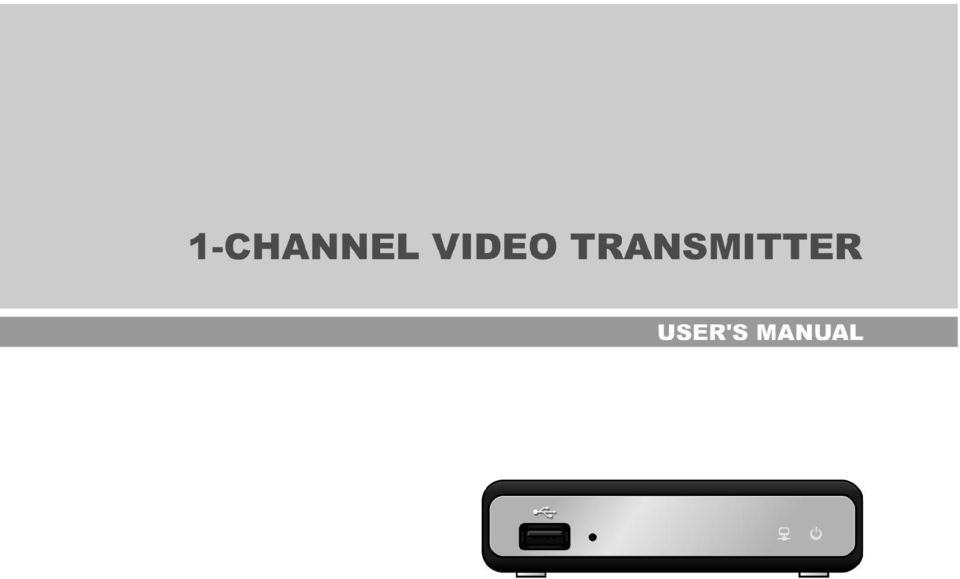
11 One-Channel Video Transmitter Chapter 2 Installation 2.1 Package Contents Network Video Transmitter DC Adapter (12V) Power Cord Installation CD (INIT, RASplus) User s Manual (This Document) RASplus User s Manual Rack-mount Kits 2.2 Front Panel USB Port Factory Reset Switch Network LED Power LED USB Port: Connect a USB flash drive to upgrade the software. Refer to Chapter 3 Operation & Basic Configuration; 3.5 Management, Upgrade for details on software upgrades. Factory Reset Switch: Use to return all settings to the original factory settings. See below for details. Network LED: Displays network connection status. Refer to Appendix A LED Indicators for details. Power LED: Displays system operating status. Refer to Appendix A LED Indicators for details. Factory Reset This switch will only be used on the rare occasions that you want to return all the settings to the original factory settings. CAUTION: When performing a Factory Reset, you will lose any settings you have saved. Disconnect the power adapter from the transmitter. Poke a straightened paperclip into the factory reset switch hole. Connect the power while holding the reset switch Release the switch when the Network and Power LEDs blink together. The transmitter resets to factory defaults and restarts after completing the factory reset. You can perform a factory reset while the transmitter is turned on by poking a straightened paperclip into the factory reset switch hole and releasing the reset switch. A factory reset also can be performed remotely by running the INIT program and selecting the Reset Factory Reset menu. The transmitter restarts after completing the factory reset. Refer to Chapter 3 Operation & Basic Configuration; 3.4 Reset, Factory Reset for details on remote factory resetting. 5

12 User s Manual 2.3 Rear Panel Network Port Audio Out Audio In Video In Video Termination Resistance Switch RS485 Port DC 12V Out Alarm Output GND Alarm Input Power In Network Port: Connect a Cat5 cable with an RJ-45 jack. Refer to Chapter 3 Operation & Basic Configuration; 3.2 Setup, IP Address Setup for details on network connection setup. When using a PoE switch, the transmitter can be supplied with power over Ethernet. (Refer to the PoE switch manufacturer s manual for details.) Audio Out: Connect to an amplifier. (Line-out) Audio In: Connect to an audio source. (Line-in or Microphone) Video In: Connect coaxial cables from the video sources (NTSC or PAL). Video Termination Resistance Switch: Push down the video termination resistance switch to turn it on. RS485 Port: Connect to a PTZ camera. Connect TX+/RX+ and TX-/RX- of the PTZ camera to the + and (respectively) of the transmitter. Refer to Chapter 3 Operation & Basic Configuration; 3.2 Setup, Camera/Audio Setup and the PTZ camera manufacturer s manual for configuring the RS485 connection. DC 12V Out: Connect the power wires from the camera (12 VDC). The camera can be supplied power from the transmitter when using 12 VDC power. Connect + and of the camera to the + and (respectively) of the transmitter. Alarm Output: Connect an alarm-out device to the NO (Normally Open) and C (Common) connectors. NO is a relay output which sinks 125 VAC and 30 VDC. GND: Connect to the ground side of the alarm inputs. Alarm Input: Connect alarm-in devices. Mechanical or electrical switches can be wired to the AI (Alarm-In) and GND (Ground) connectors. The maximum voltage should not exceed 5V. The threshold voltage for NC (Normally Closed) is above 4.3V and for NO (Normally Open) is below 0.3V, and it should be stable at least 0.5 seconds to be detected. Power In: Connect two wires from the power adapter (12 VDC or 24 VAC). The transmitter starts booting as soon as power is applied. NOTES: The transmitter does not have amplified audio output, so you will need a speaker with an amplifier. To make connections on the Alarm Connector Strip, press and hold the button and insert the wire in the hole below the button. After releasing the button, tug gently on the wire to make certain it is connected. To disconnect a wire, press and hold the button above the wire and pull out the wire. Camera and audio surveillance may be prohibited by laws that vary by region. Check the laws in your area before using this product for surveillance purposes. CAUTION: The transmitter restarts after the power adaptor is disconnected from the transmitter when switching the power source from 12 VDC or 24 VAC to PoE. 6
 Audio Out: Connect to an amplifier.")
13 One-Channel Video Transmitter CAUTION: The network connector is not designed to be connected directly with cable or wire intended for outdoor use. WARNING: ROUTE POWER CORDS SO THAT THEY ARE NOT A TRIPPING HAZARD. MAKE CERTAIN THE POWER CORD WILL NOT BE PINCHED OR ABRADED BY FURNITURE. DO NOT INSTALL POWER CORDS UNDER RUGS OR CARPET. THE POWER CORD HAS A GROUNDING PIN. IF YOUR POWER OUTLET DOES NOT HAVE A GROUNDING PIN RECEPTACLE, DO NOT MODIFY THE PLUG. DO NOT OVERLOAD THE CIRCUIT BY PLUGGING TOO MANY DEVICES INTO ONE CIRCUIT. 2.4 INIT Program Installation The INIT (Integrated Network Installation Tool) program should be installed in your computer to operate the transmitter. Computer system requirements for installing the INIT program are: Operating System: Microsoft Windows XP or Microsoft Windows Vista CPU: Intel Pentium IV (Celeron) 2.4GHz or faster RAM: 512 MB or more VGA: AGP, Video RAM 8MB or more (1024x768, 24bpp or higher) CAUTION: If an older version of INIT software is installed on your computer, you should uninstall the older version first. 1. Insert the installation CD. 2. Run the setup.exe file in the INIT folder, and install the software following the instructions. 3. Click Accept. NOTE: Installing.NET Framework is required for INIT to operate properly. This installation step will be skipped if.net Framework is installed on your computer. 4. Click Install. NOTE: Visual C++ Runtime Libraries must be installed for INIT to operate properly. This installation step will be skipped if Visual C++ Runtime Libraries are installed on your computer. 7
 program should be installed in your computer to operate the transmitter.")
14 User s Manual 5. Click Next. 6. Select Everyone to allow all users logged onto the computer with any user account to run the program, or Just me to allow only the user who is logged onto the computer with the current user account. Then, click Next. 7. Click Next. The progress bar shows the installation progress. 8. After the software is installed, set the language option by selecting either Select language when starting or Always start using the language below. NOTES: To properly display the selected language, your PC s operating system should be set to support the selected language. In order to change the language after selecting the Always start using the language below option, the software must be reinstalled. 8

15 One-Channel Video Transmitter 9. Clicking Close completes the installation. 9

16 User s Manual Chapter 3 Operation & Basic Configuration After installing the INIT software, you will find the shortcut icon on the desktop. Run the program by double clicking the icon. The following Main screen appears, and you can connect to a transmitter and change its settings. Selecting the Multiselection option allows you to select multiple transmitters and change their settings at the same time. NOTES: You will need the RASplus program for integrated remote management and monitoring of multiple transmitters. Refer to the RASplus user s manual for installing and operating the program. Do not change the IP address of your computer manually while running the INIT program. If you do, the network connection between the transmitter and your computer will be cut off. NOTES: The Multiselection option is NOT available for some functions. If your computer has more than one network adaptor, the following screen appears when running the INIT program. Select which network adaptor to communicate with the transmitter. 10

17 One-Channel Video Transmitter 3.1 Lookup You can find transmitters that are networked via LAN or WAN. When the transmitter is networked via LAN, you can find it in the lookup list. When the transmitter is networked via WAN, you can find it by entering the transmitter s IP address. Click the Lookup icon on the Main screen, and the Lookup menu appears. Look Up Devices (LAN) Select Look Up Devices (LAN) in the Lookup menu, and a list of all transmitters networked via LAN is displayed on the Main screen. Manual Connect (WAN) Select Manual Connect (WAN) in the Lookup menu. Enter the IP address or name of the transmitter to find in the IP Address field and click the Connect button. The transmitter information is displayed on the Main screen. Selecting the Use DVRNS box allows you to enter the name registered on the DVRNS server instead of the IP address. You must enter the DVRNS server address and port number in the DVRNS Server field. Refer to Chapter 4 Remote Setup; 4.3 Network, DVRNS for details. NOTE: When the transmitter is networked by using a NAT (Network Address Translation) device, you cannot find the transmitter in a WAN environment. In this case, run the INIT program in a LAN environment. 11
 Select Manual Connect (WAN) in the Lookup menu. Enter the IP address or name of the transmitter to find in the IP Address field and click the Connect button.")
18 User s Manual 3.2 Setup You can change a transmitter s settings. Select a transmitter to change settings and click the Setup icon on the Main screen. The Setup menu appears. You can also display the Setup menu by selecting a desired transmitter and clicking the right mouse button on the Main screen. NOTE: The Multiselection option for selecting transmitters is not available for IP address Setup, Video Setup, Camera/Audio Setup, Remote Setup and WebGuard. IP Address Setup You can change the IP address of a transmitter. Select a transmitter from the Main screen and select IP Address Setup from the Setup menu. Type: Choose the type of network configuration from: Manual, DHCP and ADSL (with PPPoE). Enter the proper settings for network connection. Refer to Chapter 4 Remote Setup; 4.3 Network, IP Address for details. DNS Server: Enter the IP address of the DNS server. If you set up the DNS server, the domain name can be used instead of the IP address of the server during the DVRNS server, time server and SMTP server setup. Setup DVR Name Service: Check the box to use the DVRNS (DVR Name Service) function. When you select it, the Finish button changes to Next. Clicking the Next button allows you to set up the DVRNS settings. Refer to Chapter 4 Remote Setup; 4.3 Network, DVRNS for details. Video Setup You can set up the image transfer conditions and test network bandwidth. Select a transmitter from the Main screen and select Video Setup from the Setup menu. 12

19 One-Channel Video Transmitter Drawing Mode Setup: Click to select drawing mode for the monitoring screen in the setup screen. Normal Drawing: Depends on the CPU performance of your PC and displays image in low speed (Dib Draw Mode). Fast Drawing (Default): Displays images in normal speed (Direct Draw Mode). Fast Drawing (YUV420/RGB32): Depends on the performance of the video card installed in your PC and displays images in high speed (Direct Draw Mode). Overlay Drawing (YUV420/RGB32/RGB565): Displays images in high speed (Direct Draw Overlay Mode). Image transfer conditions (Compression, Resolution, Quality, Frame Rate): You can set up the compression, resolution, quality and frame rate for transferring images to a remote site. Clicking the Apply button after setting up the image transfer conditions will apply the settings and transfer video based on the preset conditions. Clicking the Close button closes the setup screen. Network Bandwidth Test: You can check if enough bandwidth is available to transfer images with the desired image transfer settings. Click the Network Bandwidth Test button after setting the desired image transfer conditions. The program performs a test of the network bandwidth when transferring images with the current settings. The button changes to Stop, and the test results are displayed in the Bandwidth field as Enough or Not Enough. Clicking the Stop button stops the test. 13
: Displays images in high speed (Direct Draw Overlay Mode).")
20 User s Manual NOTES: If the image cannot be displayed properly because of your PC s specifications, lower the drawing mode level during Drawing Mode Setup. When you select the Fast Drawing mode during Drawing Mode Setup, the drawing speed might decrease when the monitoring screen is not located on the primary monitor. Depending on the type of video card installed in your PC, the Overlay Drawing mode may not be supported during Drawing Mode Setup. Video cards with an ATI chipset are recommended. When using dual monitors, selecting the Overlay Drawing mode during the Drawing Mode Setup setting will display the image only on the primary monitor. Simultaneous connections to the transmitter might cause a decrease in frame rate. The transmitter will be disconnected from other network connections while performing a network bandwidth test. Do NOT use other network connections on your computer while performing a network bandwidth test. Otherwise, the test might be interrupted. Camera/Audio Setup You can adjust image color, control audio in/out and control a PTZ camera. Select a transmitter from the Main screen and select Camera/Audio Setup from the Setup menu. Drawing Mode Setup: Click to select the drawing mode for the monitoring screen of the setup screen. Refer to the Video Setup section for details. Color Control: Click the target icons to adjust the brightness, contrast, saturation and hue of the image. Clicking the icon cancels the image processing operation and reloads the original image. Clicking the Apply button applies the settings. Audio Control: Select the check boxes to enable audio in or out and set the volume. You can select between Microphone or Line-in for audio in. Clicking the Apply button applies the settings. PTZ Camera: Select the PTZ camera model connected to the transmitter and set the ID, baud rate, data bit, stop bit and parity by referring to the PTZ camera manufacturer s instructions. Clicking the Apply button activates the settings and allows you to control the PTZ camera by using control icons in the bottom right corner of the screen. 14

21 One-Channel Video Transmitter NOTES: The Color Control adjustments are not meant to correct an improperly set camera. You will not be able to control a PTZ camera if it is not correctly connected to the RS485 port. See Chapter 2 Installation; 2.2 Rear Panel Connectors, RS485 Port and the PTZ camera manufacturer s manual for configuring the RS485 connection. Advanced menu control features will be enabled when a PTZ camera supports such features as Speed, Auto Pan, Tour, etc. Depending on the PTZ camera specifications, some Advanced menu features may not be active. Remote Setup You can change all settings of the transmitter remotely. See Chapter 4 Remote Setup for details. WebGuard You can monitor live video images from the transmitter on the web browser program, WebGuard. See Chapter 5 Web Monitoring for details. Apply Setup File You can apply saved settings of one transmitter to other transmitters. Select the other transmitters to change settings from the Main screen and select Apply Setup File from the Setup menu. Include Network Setup: You can select whether or not network settings (IP address, port number, DVRNS) will be included when the settings are applied. Select File: Click the button and select the desired setup file to apply to other transmitters. Clicking the OK button displays the next setup screen. A list of selected transmitters is displayed. Clicking the Start button applies the settings to the listed transmitters. The Status field displays the result as Success or Fail after completing the procedure, and the reason for the failure is displayed in the Remarks field. NOTE: The Multiselection option for selecting transmitters is available for the Apply Setup File setup. The Include Network Setup option is not available when more than one transmitter is selected. Make Setup File You can create a setup file of the current transmitter settings and save it as a.dat file format. Select transmitters to create a setup file from the Main screen and select Make Setup File from the Setup menu. When the screen to designate a folder path appears, select the folder to save the setup files in. 15
22 User s Manual A list of selected transmitters is displayed. Click the Start button, and the current settings of the listed transmitters are saved as.dat files named after the name and MAC address of each transmitter in the designated folder. The Status field displays the result as Success or Fail after completing the procedure and the reason for the failure is displayed in the Remarks field. 3.3 Test You can check the status of the alarm-in and alarm-out devices connected to a transmitter. First, check that the alarm-in and alarm-out devices are connected to the transmitter properly. Select a transmitter and click the Test icon on the Main screen. The Test menu appears. Alarm In/Out Test Alarm In: Select to test whether or not the alarm-in device is working properly. Select the proper alarm-in type. Click the Start button, and then trigger the connected alarm-in device within five seconds. The system displays whether or not the alarm in detection has succeeded. Alarm Out: Select to test whether or not the alarm-out device is working properly. Click the Start button. The alarm out is activated for three seconds when the device works properly. 3.4 Reset You can restart transmitters or reset transmitter settings. Select the transmitters to reset and click the Reset icon on the Main screen. The Reset menu appears. Soft Reset You can restart the transmitters. Select the transmitters and click Soft Reset in the Reset menu. 16
23 One-Channel Video Transmitter A list of selected transmitters is displayed. Clicking the Start button starts the soft reset process for the listed transmitters. The Status field displays the result as Success or Fail after completing the procedure and the reason for the failure is displayed in the Remarks field. Factory Reset You can return all settings of transmitters to the original factory settings. Select the transmitters and click Factory Reset in the Reset menu. Click the OK button. You can select whether or not network settings (IP address, port number, DVRNS) will be included when the factory reset is done. A list of selected transmitters is displayed. Clicking the Start button starts the factory reset on the listed transmitters. The Status field displays the result as Success or Fail after completing the procedure and the reason for the failure is displayed in the Remarks field. The transmitters restart after completing the factory reset. 3.5 Management You can upgrade transmitters or display their system logs. Select the transmitters to manage and click the Management icon on the Main screen. The Management menu appears. NOTE: The Multiselection option for selecting transmitters is not available for System log. Upgrade You can upgrade transmitters. Select the transmitters and click Upgrade in the Management menu. 17
24 User s Manual Click the Select File button and select the desired upgrade file. Click the OK button. A list of selected transmitters is displayed. Clicking the Start button starts upgrading the listed transmitters. The Status field displays the result as Success or Fail after completing the procedure and the reason for the failure is displayed in the Remarks field. The transmitters restart after completing the upgrade. You also can upgrade a transmitter by using a USB flash drive. Disconnect power from the transmitter and connect a USB flash drive containing the upgrade package file (.rui and autorun.txt) to the transmitter. Connect power to the transmitter, and the transmitter will be upgraded automatically. NOTE: While a transmitter is being upgraded, the Network LED and Power LED flicker sequentially. CAUTIONS: Do NOT alter the upgrade file, or else, the transmitter might not work properly. Do NOT disconnect the power while the transmitter is being upgraded. Doing so might damage the transmitters. System Log You can display the system log of a transmitter. Select the transmitter and click System Log in the Management menu. From: Click to set the search starting date and time. When First is selected, it will search from the first log. To: Click to set the search ending date and time. When Last is selected, it will search through the last log. Find: Click to display log entries within the selected period. A maximum of 100 logs can be displayed per page. Print: Click to print the log information. Save: Click to save the log information on the screen as a text file. Move Buttons: Click the or button to move to the previous or next page. Close: Click to close the log screen. 18
25 One-Channel Video Transmitter Chapter 4 Remote Setup Remote Setup allows you to change all settings of the transmitter. (You can also change the settings by using the RASplus program.) Select a transmitter to change settings and click the Setup icon on the Main screen. Select Remote Setup from the Setup menu and the Remote Setup screen appears. NOTE: The Multiselection option for selecting transmitters is not available for the remote setup. Clicking a menu in the left of the Remote Setup screen displays the current settings for that menu on the right side of the screen. Clicking submenus under each menu allows you to change the settings. Clicking the OK button closes the Remote Setup screen and applies the changes. 4.1 Quick Setup The Quick Setup allows you to change a transmitter s basic system, network, video and audio settings. When you click the Quick Setup menu on the Remote Setup screen, the current Quick Setup settings are displayed on the right side of the screen. Refer to the explanations below for details of each submenu setup. 19
26 User s Manual 4.2 System You can change a transmitter s system information, import or export all settings, and add users or groups. When you click the System menu on the Remote Setup screen, the current System settings are displayed on the right side of the screen. General Language: Choose the language to be used during remote setup. Name: Enter the transmitter s name (up to 31 characters including spaces). Note: Enter additional information about the transmitter. HW Version, SW Version: These fields display the transmitter s hardware and software versions. Setup Load Default Setup : Click to return all except network related settings to the original factory settings. Import Setup : Click to apply the settings saved as a.dat file format to the transmitter. A setup screen appears allowing you to select the setup file. You can select whether or not network settings (IP address, port number, DVRNS) will be included when the setup is applied. Export Setup : Click to save the current transmitter settings as a.dat file format. A setup screen appears allowing you to name the setup file. Date/Time Date/Time: Change the system date/time, date/time format and time zone and turn daylight saving time on or off by checking the box. Clicking the Apply button applies the changes immediately. Time Sync Automatic Sync: Check the box to automatically synchronize the time with a time server. Enter the IP address or the domain name of the time server and set the time interval for synchronization. Run as Server: Check the box to run the transmitter as a time server. NOTE: You can use the domain name instead of the IP address of the time server during the Time Sync setting if you set up the DNS Server when setting up network. 20
27 One-Channel Video Transmitter User/Group User/Group: Click the buttons to change the settings for a group or a user allowed to control the transmitter remotely. Add Group: Click to add a group. Enter the desired group name and set authority levels for the group to control the transmitter remotely. Add User: Click to add a user. Enter the desired user name and select the group that the user will belong to. Enter a password to be assigned to the user. Change: Select a group and click the button to change authority levels assigned to the group, or select a user and click the button to change the user s password. Delete: Select a group or user and click the button to delete the group or user. Allow Anonymous Login: Check the box to use the webcasting feature. Refer to 4.4 Video Webcasting for details. Allow Anonymous PTZ Control: Check the box to allow remote control of a PTZ camera on a website by using the webcasting feature. NOTES: The User/Group changes are permitted only to the users in the Administrator group. The authority levels that can be assigned are: Upgrade: The user can upgrade the software. Setup: The user can set up the system. Color Control: The user can control brightness, contrast, hue and saturation for cameras. PTZ Control: The user can control a PTZ camera. Alarm-Out Control: The user can reset the output during an alarm. System Check: The user can view and check the remote system status. 4.3 Network You can change the network settings and set up DVRNS and IP filtering functions. When you click the Network menu on the Remote Setup screen, the current Network settings are displayed on the right side of the screen. 21
28 User s Manual IP Address Type: Select the type of network configuration. Manual: Select when the transmitter is using a static IP address for network connection, and set up LAN parameters manually. DHCP: Select when the transmitter is networked via DHCP (Dynamic Host Configuration Protocol). Click the OK button, and a temporary IP address is automatically assigned to the transmitter. The transmitter periodically will be issued a new IP address automatically. ADSL: Select when the transmitter is networked via ADSL. Enter the ID and password for ADSL connection, and click the OK button. A temporary IP address is automatically assigned to the transmitter. The transmitter periodically will be issued a new IP address automatically. DNS Server: Enter the IP address of the DNS server. If you set up the DNS server, the domain name of the server can be used instead of the IP address when the DVRNS, time and SMTP servers are set up. Ask your Internet service provider for the IP Address of the DNS Server. NOTES: Ask your network provider for details about the network connection type and connection information for the transmitter. If the transmitter is configured for a DHCP or ADSL network, it is best to use the DVRNS function because the transmitter s IP address might change frequently. Ask your Internet service provider for information about the IP Address of the DNS Server. DVRNS Check the DVR Name Service box to use the DVR Name Service function. DVRNS Server: Enter the IP address or domain name of the DVRNS server. Port: Set up the port number of the DVRNS server. Use NAT: Check the box when using NAT (Network Address Translation). DVR Name: Enter the transmitter s name to be registered on the DVRNS server. Check whether or not the name is available by clicking the Check button. Help Desk: Choosing the OK button registers the transmitter on the DVRNS server. Proper DVRNS settings will display the help desk information of the DVRNS server. NOTES: The DVRNS (DVR Name Service) allows you to connect to the transmitter using either the dynamic IP addresses or the domain name. For the DVRNS feature to work properly, the transmitter should be registered on the DVRNS server, and the DVRNS server settings in the INIT program for the transmitter should match the settings registered on the DVRNS server. Any changes on the DVRNS server might cause improper operation. When LAN settings have been changed, set up the DVRNS settings after saving your LAN changes by clicking the OK button. 22
29 One-Channel Video Transmitter NOTES: You will need to get the IP address or domain name of the DVRNS server from your network administrator. You can use the domain name instead of IP address if you set up the DNS server during the IP Address setup. When using a NAT (Network Address Translation) device, refer to the NAT manufacturer s instructions for the proper network settings. The transmitter s name you entered in the DVR Name field should be checked by clicking the Check button, otherwise the DVRNS changes will not be saved. When entering no name or a name already registered on the DVRNS server, an error message displays. Port Set up Admin, Watch, Record, Audio and WebGuard port numbers for connections to the transmitter from remote software or the WebGuard program. Check the Use HTTPS box to enhance the security of WebGuard pages by using the HTTPS protocol when running the WebGuard program. NOTES: The transmitter restarts automatically after changing the port settings. Do NOT use the same port number for more than one function, or else, the transmitter cannot be connected with RASplus or WebGuard. CAUTION: When changing the port settings, you must change the port settings on RASplus too. Filtering & Bandwidth IP Filtering: Check the box to use the IP filtering function. You can allow or block connections to the transmitter by designating IP addresses. Allow List: Check the box to add or remove IP addresses allowed to connect to the transmitter. When clicking the Add button, a screen appears allowing you to enter IP addresses. Selecting an IP address in the list and clicking the Remove button deletes the selected IP address. Clicking the Remove All button deletes all IP addresses. Deny List: Check the box to add or remove IP addresses to block connection to the transmitter. When clicking the Add button, a screen appears allowing you to enter IP addresses. Selecting an IP address in the list and clicking the Remove button deletes the selected IP address. Clicking the Remove All button deletes all IP addresses. While adding IP addresses to Allow List or Deny List, selecting the Host option allows you to add one IP address at a time. Selecting the Group option allows you to add continuous IP address numbers in one action by designating a range of IP addresses to add. 23
30 User s Manual Network bandwidth limit: Check the box to limit the network bandwidth and set the desired maximum bandwidth. NOTES: If you want to use the time synchronization, DVRNS and sending functions, the IP addresses of the time server, DVRNS server and the SMTP server must be allowed when you allow or block connection to the transmitter in the Allow List or Deny List. Any connection to the transmitter from the IP address in Deny List will NOT be allowed. 4.4 Video You can set camera features and image transfer parameters for both remote monitoring and webcasting. When you click the Video menu on the Remote Setup screen, the current Video settings are displayed on the right side of the screen. Camera PTZ Product / ID: Select a PTZ camera connected to the transmitter and assign an ID to the PTZ camera. Baud Rate, Data Bit, Stop Bit, Parity: Set up baud rate, data bit, stop bit and parity by referring to the PTZ camera manufacturer s instructions. NOTE: You will not be able to control a PTZ camera if it is not connected to the RS485 port properly. See Chapter 2 Installation; 2.3 Rear Panel Connectors, RS485 Port and the PTZ camera manufacturer s manual for configuring the RS485 connection. Live Monitoring Select the desired Compression, Resolution, Quality and Frame Rate for transferring images to a remote site. Allow dynamic configuration: Check the box to allow the image transfer settings to be changed dynamically based on the settings of the other device that is receiving images from the transmitter. NOTE: Simultaneous connections to the transmitter might cause the frame rate to decrease. 24
31 One-Channel Video Transmitter Webcasting You can stream live video from the transmitter to a website. Copy the HTML Code displayed on the screen and paste it in your web page code. NOTE: To use the webcasting service, you must check the Allow Anonymous Login option during 4.2 System User/Group setup. 4.5 Audio You can set up audio in and out. When you click the Audio menu in the Remote Setup screen, the current Audio settings are displayed on the right side of the screen. Input/Output Audio In: Check the box to enable audio in and select the proper audio-in device. You can also adjust the volume. Audio Out: Check the box to enable audio out. You can also adjust the volume. NOTE: The transmitter does not have amplified audio output, so you need to use a speaker with an amplifier. 25
32 User s Manual 4.6 Event You can set up event detection and actions to be taken. When you click the Event menu on the Remote Setup screen, the current Event settings are displayed on the right side of the screen. Alarm In Check the Alarm In box to set up an alarm-in event. When the transmitter senses an input on the alarm input connector, it considers it as an event. Enter the alarm-in device s name and select the alarm-in type. Event Action: Check the box for each action the transmitter will take whenever it detects an alarm-in event. Alarm Out: Select to trigger an alarm-output signal. Send Select to send an . Selecting a camera in the Image Attachment field attaches the event detected image file (.JPG) when sending an . Remote Callback: Select to send a message to remote sites and select the desired remote sites. Move PTZ to: Select the desired preset number to move a PTZ camera to the previously saved preset location. You must set up preset locations of PTZ cameras during 3.2 Setup Camera/Audio Setup. NOTE: You must properly configure the settings related to each event action during the 4.6 Event Event Action setup to enable event actions. Motion Detection Check the Motion Detection box to set up a motion detection event. When the transmitter detects a motion in a configured motion detection zone, it considers the motion as an event. Sensitivity: Set the motion sensitivity for daytime and nighttime independently. Minimum Blocks for Detection: Adjust the minimum number of detection blocks (1 to 192) that must be activated to be considered as a motion event for daytime and nighttime independently. 26
33 One-Channel Video Transmitter Motion Zone: Click the Setup button and a motion detection zone setup screen appears. Define the area of the image that you want to set up a motion detection zone by using the motion detection zone icons. (Select) or (Clear): Click to select or clear blocks for motion detection. or (One or All block): Click to select or clear one or all blocks at a time. (Area): Click to select or clear several blocks of an area. Motion Ignoring Interval: Select the motion ignoring dwell time from the drop-down list. The transmitter will not log or send notifications of motion events occurring during the preset interval range. You can control excessive event logging and remote notifications of motion detection events by adjusting the motion ignoring dwell intervals. Daytime: Set up the daytime range. The transmitter will consider the remaining time range as the nighttime. Event Action: Check the box for each action the transmitter is to take when it detects a motion detection event. Alarm Out: Select to trigger an alarm-output signal. Send Select to send an . Selecting a camera in the Image Attachment field attaches the event detected image file (.JPG) when sending an . Remote Callback: Select to send a message to remote sites and select the desired remote sites. Move PTZ to: Select the desired preset number to move a PTZ camera to the previously saved preset location. You must set up preset locations of PTZ cameras during 3.2 Setup Camera/Audio Setup. NOTE: You must properly configure the settings related to each event action during the 4.6 Event Event Action setup to enable event actions. Video Loss When the transmitter has lost video, it considers the video loss as a video loss event. Event Action: Check the box for each action the transmitter will take whenever it detects a video loss event. Alarm Out: Select to trigger an alarm-output signal. Send Select to send an . Remote Callback: Select to send a message to remote sites and select the desired remote sites. NOTE: You must properly configure the settings related to each event action during the 4.6 Event Event Action setup to enable event actions. 27
34 User s Manual Video Blind Check the Video Blind box to set up a video blind event. When the transmitter detects that more than 70% of a camera is blinded by anything, it considers the video blind as an event. Sensitivity: Adjust the sensitivity for the video blind. Activation Time: Adjust the duration that a video blind should last to be considered a video blind event. The transmitter will not consider any video blind as a video blind event if it is shorter than the preset time. Use Ignoring Time: Set up the event ignoring time. The transmitter will ignore video blind events occurring during the preset time. Event Action: Check the box for each action the transmitter will take whenever it detects a video blind event. Alarm Out: Select to trigger an alarm-output signal. Send Select to send an . Selecting a camera in the Image Attachment field attaches the event detected image file (.JPG) when sending an . Remote Callback: Select to send a message to remote sites and select the desired remote sites. Move PTZ to: Select the desired preset number to move a PTZ camera to the previously saved preset location. You must set up preset locations of PTZ cameras during 3.2 Setup Camera/Audio Setup. NOTES: Video blind events might NOT be detected for a camera with a very noisy image especially when set for low Sensitivity values. You must properly configure the settings related to each event action during the 4.6 Event Event Action setup to enable event actions. System Event Check the System Event box to set up a system event. The transmitter checks and reports the system and alarm-in status. System: Select the check interval. The transmitter sends an when the system is operating. Alarm In: Select the check interval. The transmitter sends an when there is no alarm-in event status change. NOTE: You must properly configure the settings during the 4.6 Event Event Action setup to send an . 28
35 One-Channel Video Transmitter Event Action You can set up event actions to notify the event detection when the transmitter detects events. Alarm Out: Check the box to activate alarm out. Type: Select the type of alarm-out device. Dwell Time: Select the alarm-out dwell time. An alarm out is activated for the preset dwell time after detecting an event. Schedule: Set up the period to enable alarm out. An alarm out can be activated only during this period. Check the box to send an . SMTP Server, Port: Enter the IP address or domain name and port number of the SMTP server. Select Use SSL/TLS if the SMTP server requires SSL (Secure Sockets Layer) authentication. Authentication ID, Password: Enter the ID and password if the SMTP server requires user authentication. Sender, Recipient: Enter the sender s and recipients address. Up to 10 recipients can be added. Remote Callback: Check the box to send a callback message to remote sites. Retry: Select the number of times to try sending a message if it fails to send. Setup: Enter the IP addresses and port numbers of the remote sites to send a message. NOTES: You will need to get the IP address or domain name of the SMTP server from your network administrator. You can use the domain name instead of the IP address if you set up the DNS server when setting up the network. An address must include character to be a valid address. 29
36 User s Manual Chapter 5 Web Monitoring You can monitor live video images from the transmitter on the web browser program, WebGuard. Computer system requirements for using WebGuard are: Operating System: Microsoft Windows 2000, Microsoft Windows XP or Microsoft Windows Vista CPU: Intel Pentium III (Celeron) 600MHz or faster RAM: 128MB or more VGA: 8MB or more (1024x768, 24bpp or higher) Internet Explorer: Version 6.0 or later Start Internet Explorer on your local PC. You can run the WebGuard program by entering the following information in the address field. address:port number (The transmitter s IP address and the WebGuard port number set during the port setup) Or, server address/transmitter s name (The DVRNS server address and the transmitter s name registered on the DVRNS server) NOTES: Enter https instead of http if you have checked the Use HTTPS box during the WebGuard port number setup. Click Continue to this website (not recommended) when the security certificate warning page is displayed. When the WebGuard login page is not displayed, check Internet option settings as follows: Go to Tools, then Internet Options, and then the Security tab Click the Custom level button Set the setting of Reset custom settings to Medium-high (default) or Medium. Go to Tools, then Internet Options, and then the Advanced tab Check the Use TLS 1.0 box under the Security option. You do not need to enter the WebGuard port number if the WebGuard port number is set to 80 (443 when entering https) when running the WebGuard program by entering the IP address and port number. Enter the appropriate port number of the WebWatch program and audio set during the Chapter 4 Remote Setup; 4.3 Network, Port setup. Entering your ID and PASSWORD and clicking the [LOGIN] button logs in. Selecting Save ID saves the ID you entered. NOTES: The port numbers for WEBWATCH and AUDIO should be the same port numbers used for Watch and Audio that were set during the port setup (Chapter 4 Remote Setup; 4.3 Network, Port). WebGuard only works with Microsoft Internet Explorer and will NOT work with Netscape or other web browsers. There might be a problem with the bottom of the WebGuard page being cropped caused by the address or status bars in Microsoft Internet Explorer 7.0. In this situation, it is recommended that websites open windows without address or status bars by changing Internet setting. (Go to Tools, and Internet Options, and then the Security tab Click the Custom level button Select Enable for the Allow websites to open windows without address or status bars option.) 30
37 One-Channel Video Transmitter NOTES: y When running WebGuard in the Microsoft Windows Vista operating system, it is recommended that you start Internet Explorer with elevated administrator permissions. Click the right mouse button on the Internet Explorer icon and select the Run as administrator option from the context menu. Otherwise, some functions of WebGuard might be limited. y There might be a problem with screen display or screen update caused by low image transmission speed when using the Microsoft Windows Vista operating system. In this situation, it is recommended that you disable the Auto Tuning capability of your computer. Run the Command Prompt with elevated administrator permissions (Go to the Start Menu, and Accessories, and then Command Prompt ĺ Click the right mouse button and select the Run as administrator option). Then enter netsh int tcp set global autotuninglevel=disable and press the enter key. Restart your computer to apply the changes. If you want to enable the Auto Tuning capability again, enter netsh int tcp set global autotuninglevel=normal after running the Command Prompt with elevated administrator permissions. Restart your computer to apply the changes. y When running the updated WebGuard for the first time, Internet Explorer might occasionally load the information from the previous version. In this case, delete the temporary Internet files by selecting Tools ĺ Internet Options ĺ General tab, and then run WebGuard again. y You will need to get the appropriate IP address for the transmitter you want to connect to and the WebGuard port number from your network administrator. ཛ Log Out: Click to log out of the WebGuard program. ཛྷ Version: Position the mouse pointer on the WebWatch logo to see the WebGuard program version. ཝ Information: The Information window displays the login information of WebGuard. ཞ Full Display: Clicking the button displays the video in full screen. Pressing the Esc button on a keyboard returns to the previous screen. ཟ Camera Button: The button displays the camera number. འ Image Adjustment: Click image. ཡ PTZ Control: Click to adjust the brightness, contrast, saturation and hue of monitored to control pan, tilt and zoom of the camera from a remote site. 31
38 User s Manual Alarm-Out Control: Click to control an alarm out device at the remote site. Save Image: Click to save the current image as a bitmap or JPEG file format. Setup: Click to set up the image drawing mode and OSD display. You can adjust the display speed by changing the image drawing mode, and select OSD information to be displayed on the screen. Event Status Window: The event status window at the bottom displays a list of events that were detected from the remote site. Alarm In On Alarm In Off Alarm In Bad Motion Detection Video Loss Video Blind Screen Popup Menu: Clicking the right mouse button on the screen displays the screen popup menu. Change Camera Title: Select to change the camera title. Enable Audio: Select to enable audio communication with the remote site and the audio control panel appears. Click the button to send audio to the remote site and speak into the microphone. Click the button to monitor live audio from the remote site through the attached speaker. Clicking both the and buttons allows two-way communication. Clicking the button disables audio communication. Aspect Ratio: Select to change the image aspect ratio displayed on the screen and the option menu appears. Selecting Fit to Screen displays images by fitting them to the screen size. Selecting Original Ratio displays images by fitting them to the screen size while maintaining their original ratio. Selecting Half Size (x0.5) to Quadruple Size (x4) displays the images at the selected image size. Draw Motion Block: Select to display the area that detects motions on the screen in red blocks. Deinterlacing: Select to enhance image display quality of interlaced video on the screen by eliminating horizontal scan lines or noise in areas with motion. Anti-Aliasing Screen: Select to enhance image display quality by eliminating stair stepping (aliasing) effects in the enlarged image. NOTES: The image adjustment for the monitoring screen works only in the pause mode. Aspect Ratio Half Size (x0.5) to Aspect Ratio to Quadruple Size (x4) in the Screen Popup Menu will be enabled when the selected camera screen can display images in those sizes. Draw Motion Block option in the Screen Popup menu is available only when a Motion Detection event is set up during the 4.6 Event, Motion Detection setup. 32
39 One-Channel Video Transmitter Appendix LED Indicators LED Status Description Unlit No power connected to the unit. Power LED Flicker The unit is booting. Lit The unit is operating. Network LED Lit The unit is connected to a network. Power LED & Network LED Flicker sequentially Flicker simultaneously The unit is upgrading the software. The unit is recovering NAND flash memory. Troubleshooting No Power Problem No Live Video Live Video Very Bright Connection to the INIT program is not available because of wrong ID and password. The WebGuard program is not available. Possible Solution Check power cord connections. Confirm that there is power at the outlet. Check camera video cable and connections. Confirm that the camera has power. Check camera lens settings. Check network connections on your PC and a transmitter. Check if a video termination resistance switch is set to ON (downward). If you lost the administrator ID and password, do a factory reset. The factory reset returns all the settings including network settings to the original factory settings. You must customize all settings including network settings after a factory reset. If you cannot launch the login page of the WebGuard program, check Microsoft Internet Explorer s version. WebGuard might not run properly in versions earlier than 6.0. Connector Pin Outs I/O Connector AI GND NO C Alarm Inputs GND (Chassis Ground) Alarm Out (Normally Open) Common 33
40 User s Manual RS485 Connector Master Unit Slave Unit + To TX+/RX+ To TX-/RX- Map of Screens INIT Program 34
41 One-Channel Video Transmitter Remote Setup 35
42 User s Manual Specifications Signal Format Input Input Resolution Compression Compression Resolution Frame Rate (Live/Recording) (images per second) DC 12V Output Alarm Input Alarm Output Network Connectivity Audio Input Audio Output VIDEO NTSC or PAL (auto detect) Composite: 1 input, 1 Vp-p, switch-terminating, 75 Ohms Composite: 720x480 (NTSC), 720x576 (PAL) MPEG-4, M-JPEG (Four levels) NTSC: 704x480, 704x240, 352x240 PAL: 704x576, 704x288, 352x288 NTSC: 30 ips/30 4CIF (Dual streaming) PAL: 25 ips/25 4CIF (Dual streaming) INPUTS/OUTPUTS 12 VDC, Max. 6W 1 TTL, NC/NO programmable, 4.3V threshold, 5 VDC 1 relay out, NO only, 125 VAC, 30 VDC 10/100 Mbps Ethernet 1 line in or Microphone 1 line out CONNECTORS Video Input BNC Audio In/Out Stereo Alarm In/Out Terminal block Ethernet Port RJ-45 RS-485 Serial Port Terminal block DC 12V Out Terminal block USB Port 1 on front panel (2.0) GENERAL Dimensions (W x H x D) 4.7" x 1.1" x 4.3" (119mm x 29mm x 108mm) Shipping Dimensions (W x H x D) 10.4" x 4.1" x 7.5" (265mm x 105mm x 190mm) Unit Weight 0.64 lbs. (0.29Kg) Shipping Weight 2.78 lbs. (1.26Kg) Operating Temperature 32 F to 122 F (0 C to 50 C) Operating Humidity 0% to 90% Power Supply 12 VDC, 24 VAC, PoE (Power over Ethernet) (IEEE 802.3af) Power Consumption Max. 5W Approval FCC, CE Specifications are subject to change without notice. 36 V1.0
esata External Storage
 esata External Storage Operation Manual DA-ES110 Before reading this manual This operation manual contains basic instruction on installing and using esata External Storage, an IDIS product. Users who are
IDIS Solution Suite. Backup Service. Software Manual. Powered by
 Solution Suite Software Manual Backup Service Powered by Before reading this manual This Operation Manual provides instructions for using Solution Suite, a network integration solution enabling remote
IDIS Solution Suite. Backup Service. Software Manual. Powered by
 Solution Suite Software Manual Backup Service Powered by Before reading this manual This Operation Manual provides instructions for using Solution Suite, a network integration solution enabling remote
IP Box Camera ACM-5711. Ver. 081016. Hardware User s Manual
 IP Box Camera ACM-5711 Ver. 081016 Hardware User s Manual 0 0 PRECAUTIONS 1. Read these instructions All the safety and operating instructions should be read before the product is operated. 2. Heed all
Table of Contents. Chapter 5 Backed-up Video Playback & Exportation... 29 5.1 Playing back Backed-up Video... 29 5.2 Exporting Backed-up Video...
 inex Backup Table of Contents Chapter 1 Introduction... 1 1.1 System Diagram... 2 Backup Service Registered on Administration Service... 2 Backup Service Registered on Federation Service... 3 Chapter 2
WARNING RISK OF ELECTRIC SHOCK DO NOT OPEN
 Network Camera WARNING RISK OF ELECTRIC SHOCK DO NOT OPEN WARNING: TO REDUCE THE RISK OF ELECTRIC SHOCK, DO NOT REMOVE COVER (OR BACK). NO USER-SERVICEABLE PARTS INSIDE. REFER SERVICING TO QUALIFIED SERVICE
FB-500A User s Manual
 Megapixel Day & Night Fixed Box Network Camera FB-500A User s Manual Quality Service Group Product name: Network Camera (FB-500A Series) Release Date: 2011/7 Manual Revision: V1.0 Web site: Email: www.brickcom.com
IDIS Solution Suite. Streaming Service. Software Manual. Powered by
 Solution Suite Software Manual Streaming Service Powered by Before reading this manual This Operation Manual provides instructions for using Solution Suite, a network integration solution enabling remote
Table of Contents. Chapter1. Introduction...1. 1.1 Before Installation... 1 1.2 System Requirements... 1
 Table of Contents Chapter1. Introduction...1 1.1 Before Installation... 1 1.2 System Requirements... 1 Chapter2. IVS-110 1-Channel Internet Video Server...2 2.1 Package Content... 2 2.2 Physical Installation...
XPanel V2. Remote Control Panel. User Manual. XILICA Audio Design
 XPanel V2 Remote Control Panel User Manual XILICA Audio Design Important Safety Instructions 1. READ THESE INSTRUCTIONS All the safety and operating instructions should be read before the product is operated.
4-CH Video Server SED-2310Q. Ver. 061031. User s Manual
 4-CH Video Server SED-2310Q Ver. 061031 User s Manual 0 0 PRECAUTIONS 1. Read these instructions All the safety and operating instructions should be read before the product is operated. 2. Heed all warnings
Box Camera Series Hardware Manual
 Encoder Firmware V4.06.09 User s Manual Box Camera Series Hardware Manual D21 (D21F / D21V) D22 (D22F / D22V) E21 (E21F / E21V) E22 (E22F / E22V) E23, E24, E25 2013/08/27 Table of Contents Precautions...
WARNING RISK OF ELECTRIC SHOCK DO NOT OPEN
 Network Camera WARNING RISK OF ELECTRIC SHOCK DO NOT OPEN WARNING: TO REDUCE THE RISK OF ELECTRIC SHOCK, DO NOT REMOVE COVER (OR BACK). NO USER-SERVICEABLE PARTS INSIDE. REFER SERVICING TO QUALIFIED SERVICE
RASplus (Remote Administration System)
") RASplus (Remote Administration System) Digital Video Recorder Software User Guide Document 800-05056 Rev C 11/09 Revisions Issue Date Revisions A 09/09 New document based on 900.0857 rev 6.00 with updates
RASplus (Remote Administration System) Digital Video Recorder Software User Guide Document 800-05056 Rev C 11/09 Revisions Issue Date Revisions A 09/09 New document based on 900.0857 rev 6.00 with updates
Table of Contents. Chapter 1 Overview... 1 1.1 In This Manual... 1 1.2 Speco Central Features... 1 1.3 Product Information... 1
 Speco Central Table of Contents Chapter 1 Overview... 1 1.1 In This Manual... 1 1.2 Speco Central Features... 1 1.3 Product Information... 1 Chapter 2 Installation... 3 Chapter 3 Configuration... 9 3.1
Outdoor-Ready Box. Hardware Manual KCM-5211E, KCM-5311E KCM-5511, KCM-5611. Ver. 2014/10/15
 Outdoor-Ready Box Hardware Manual KCM-5211E, KCM-5311E KCM-5511, KCM-5611 Ver. 2014/10/15 Table of Contents Precautions 3 Safety Instructions... 4 Introduction 6 Package Contents... 6 Physical Description...
LOREX CLIENT Remote Software 4.0
 LOREX CLIENT Remote Software 4.0 Instruction Manual English Version 2.0 MODEL: L20WD800 Series www.lorexcctv.com Copyright 2008 LOREX Technology Inc. Table of Contents Table of Contents Software Installation...
BlackHawk for MAC Software User Guide
 BlackHawk for MAC Software User Guide Products: BLK-DH2 Series and BLK-HD Series DVRs Please read this manual before using your software, and always follow the instructions for safety and proper use. Save
User Manual V1.0. Remote Software
 User Manual V1.0 Notice: The information in this manual was current when published. The manufacturer reserves the right to revise and improve its products. All specifications are therefore subject to change
RASplus (Remote Administration System)
") RASplus (Remote Administration System) Digital Video Recorder Software User Guide Document 900.0857 Rev 1.01 Revisions Issue Date Revisions 1.00 New document. 1.01 Minor changes. Rev 1.01 ii Document 900.0857
RASplus (Remote Administration System) Digital Video Recorder Software User Guide Document 900.0857 Rev 1.01 Revisions Issue Date Revisions 1.00 New document. 1.01 Minor changes. Rev 1.01 ii Document 900.0857
ACS CLIENT SOFTWARE USER MANUAL
 ACS CLIENT SOFTWARE USER MANUAL 1 ACS USER GUIDE 1.1 System Requirement Recommended System Requirement OS CPU VGA RAM HDD WindowXP, Vista Pentium 4, 2Ghz 1024*768, 64MB 24bit color graphic card 1GB 20MB
Table of Contents. Chapter 1 Overview... 1 1.1 In This Manual... 1 1.2 RASplus Features... 1 1.3 Product Information... 1. Chapter 2 Installation...
 Remote Administration System Plus (RASplus) Table of Contents Chapter 1 Overview... 1 1.1 In This Manual... 1 1.2 RASplus Features... 1 1.3 Product Information... 1 Chapter 2 Installation... 3 Chapter
Amcrest 960H DVR Quick Start Guide
 Amcrest 960H DVR Quick Start Guide Welcome Thank you for purchasing our Amcrest 960H DVR! This quick start guide will help you become familiar with our DVR in a very short time. Before installation and
TL-PA201 200Mbps Powerline Ethernet Adapter
 TL-PA201 200Mbps Powerline Ethernet Adapter Rev: 1.0.1 1910010156 COPYRIGHT & TRADEMARKS Specifications are subject to change without notice. is a registered trademark of TP-LINK TECHNOLOGIES CO., LTD.
Business Audio System: Music & Messaging MP3 Player. by Grace Digital Audio. User Guide. Model No. GDI-USBM10
 Business Audio System: Music & Messaging MP3 Player by Grace Digital Audio User Guide Model No. GDI-USBM10 User Guide Contents Introduction 2 Safety & General Use Information 2 Features 3 Set Up & Operation
Table of Contents. 1. Introduction...1. 2. PDU Package...2. 3. Function...3. 4. Installation...5. 5. Web Interface...7
 PDU User Manual Table of Contents 1. Introduction...1 2. PDU Package...2 3. Function...3 4. Installation...5 5. Web Interface...7 1. Introduction The PDU is an Internet ready device designed and is equipped
Ultra Thin Client TC-401 TC-402. Users s Guide
 Ultra Thin Client TC-401 TC-402 Users s Guide CONTENT 1. OVERVIEW... 3 1.1 HARDWARE SPECIFICATION... 3 1.2 SOFTWARE OVERVIEW... 4 1.3 HARDWARE OVERVIEW...5 1.4 NETWORK CONNECTION... 7 2. INSTALLING THE
ANI-9005. Instruction Manual DIGITAL INDOOR/OUTDOOR TV ANTENNA OMNI-DIRECTIONAL WITH AMPLIFIER INTRODUCTION:
 INTRODUCTION: This is a specially designed new concept antenna for digital indoor, outdoor analogue, and terrestrial HDTV broadcasting reception. It is the best solution for home reception and digital
IP Camera (L series) User manual 2013-05 V1.1
 User manual 2013-05 V1.1") Dear users, the configuration for this camera is professional, so please read the user manual carefully before using the camera. IP Camera (L series) User manual 2013-05 V1.1 Statement If the user manual
Dear users, the configuration for this camera is professional, so please read the user manual carefully before using the camera. IP Camera (L series) User manual 2013-05 V1.1 Statement If the user manual
TENVIS Technology Co., Ltd. User Manual. For H.264 Cameras. Version 2.0.0
 TENVIS Technology Co., Ltd User Manual For H.264 Cameras Version 2.0.0 Catalogue Basic Operation... 3 Hardware Installation... 3 Search Camera... 3 Get live video... 5 Camera Settings... 8 System... 8
ibaby Monitor Model: M3s User Manual
 ibaby Monitor Model: M3s User Manual Index 1 Introduction...3 1.1 The package contents...3 1.2 Product Features...3 1.3 Product Specifications...4 2 Appearance and Interface...5 2.1 Appearance...5 2.2
Stand Alone Type. Digital Video Recorder USER S MANUAL. (Real time recording 8 & 16 CH DVR) Revision Date : 2010. 6. 30.
 Revision Date : 2010. 6. 30.") Stand Alone Type Digital Video Recorder USER S MANUAL (Real time recording 8 & 16 CH DVR) Revision Date : 2010. 6. 30. INDEX 1. Front Panel - - - - - - - - - - - - - - - - - - - - - - - - - - - - - - -
Stand Alone Type Digital Video Recorder USER S MANUAL (Real time recording 8 & 16 CH DVR) Revision Date : 2010. 6. 30. INDEX 1. Front Panel - - - - - - - - - - - - - - - - - - - - - - - - - - - - - - -
Unpacking the Product. Rack Installation. Then, use the screws provided with the equipment rack to mount the firewall in the rack.
 About This Guide This guide contains step-by-step instructions for setting up the D-Link DFL-260E/860E Firewall. Please note that the model you have purchased may appear slightly different from those shown
TL-PS310U Single USB 2.0 Port MFP and Storage Server
 TL-PS310U Single USB 2.0 Port MFP and Storage Server Rev: 2.0.0 1910010313 Contents Chapter 1 Introduction... 1 1.1 Product Overview...1 1.2 Network Management...1 1.3 Components and Features...1 1.4 Hardware
User Manual. PePWave Surf / Surf AP Indoor Series: Surf 200, E200, AP 200, AP 400. PePWave Mesh Connector Indoor Series: MC 200, E200, 400
 User Manual PePWave Surf / Surf AP Indoor Series: Surf 200, E200, AP 200, AP 400 PePWave Mesh Connector Indoor Series: MC 200, E200, 400 PePWave Surf AP Series: Surf AP 200-X, E200-X, 400-X PePWave Surf
Evolution Digital HD Set-Top Box Important Safety Instructions
 Evolution Digital HD Set-Top Box Important Safety Instructions 1. Read these instructions. 2. Keep these instructions. 3. Heed all warnings. 4. Follow all instructions. 5. Do not use this apparatus near
CAUTION RISK OF ELECTRIC SHOCK NO NOT OPEN
 Evolution Digital HD Set-Top Box Important Safety Instructions 1. Read these instructions. 2. Keep these instructions. 3. Heed all warnings. 4. Follow all instructions. 5. Do not use this apparatus near
ivms-4200 Client Software Quick Start Guide V1.02
 ivms-4200 Client Software Quick Start Guide V1.02 Contents 1 Description... 2 1.1 Running Environment... 2 1.2 Surveillance System Architecture with an Performance of ivms-4200... 3 2 Starting ivms-4200...
Bullet Camera. Installation Guide. Hangzhou Hikvision Digital Technology Co., Ltd. http://www.hikvision.com
 Bullet Camera Installation Guide Hangzhou Hikvision Digital Technology Co., Ltd. http://www.hikvision.com 1 Thank you for purchasing our product. If there are any questions, or requests, please do not
CX Series. Video Recording Server. Quick Start Guide CX784 / CX788 / CX7816. Version 1.05.00
 CX Series Video Recording Server CX784 / CX788 / CX7816 Quick Start Guide Version 1.05.00 Contents 1.Introduction...1 1.1.Packages Contents...1 1.2.Hardware Features...2 1.3.Functional Features...4 1.4.Hard
Professional Surveillance System User s Manual
 Professional Surveillance System User s Manual \ 1 Content Welcome...4 1 Feature...5 2 Installation...6 2.1 Environment...6 2.2 Installation...6 2.3 Un-installation...8 3 Main Window...9 3.1 Interface...9
Quick Start Guide NVR DS-7104NI-SL/W NVR. www.hikvision.com. First Choice For Security Professionals
 Quick Start Guide NVR DS-7104NI-SL/W NVR NOTE: For more detailed information, refer to the User s Manual on the CD-ROM. You must use your PC or MAC to access the files. www.hikvision.com Quick Start 1.
MJPEG Camera Client User Manual
 MJPEG Camera Client User Manual CONTENTS User Manual 1 WELCOME... 3 1.1Features... 3 1.2Installation Requirements... 3 1.3 Software Installation... 3 2 Software Operation... 5 2.1 Tab bar... 6 2.2 Device
1.3 MEGAPIXEL WIRELESS NETWORK CAMERA SERIES
 1.3 MEGAPIXEL WIRELESS NETWORK CAMERA SERIES ADVANCED NETWORK SETUP Please read instructions thoroughly before operation and retain it for future reference. n812_813_network_v1.3 IMPORTANT SAFEGUARD All
E13. 5MP Cube with Basic WDR, Fixed lens Hardware User s Manual. (PoE) Ver. 2012/10/22
 Ver. 2012/10/22") E13 5MP Cube with Basic WDR, Fixed lens Hardware User s Manual (PoE) Ver. 2012/10/22 Table of Contents 0. Precautions 3 1. Introduction 4 Package Contents... 4 Features and Benefits... 5 Safety Instructions...
E13 5MP Cube with Basic WDR, Fixed lens Hardware User s Manual (PoE) Ver. 2012/10/22 Table of Contents 0. Precautions 3 1. Introduction 4 Package Contents... 4 Features and Benefits... 5 Safety Instructions...
1. Central Monitoring System Software
 1. Central Monitoring System Software 1-1. General information CMS program is an application with which users not only watch and control remote DVRs, but also receive video/audio data or alarm signals
aseries DVR04/DVR08 DIGITAL VIDEO RECORDER Quick Operations Guide
 aseries DVR04/DVR08 DIGITAL VIDEO RECORDER Quick Operations Guide UD.7L0202B1365B01 Thank you for purchasing our product. If there is any question or request, please do not hesitate to contact dealer.
1. Central Monitoring System Software
 1. Central Monitoring System Software 1-1. General information CMS program is an application with which users not only watch and control remote DVRs, but also receive video/audio data or alarm signals
BiPAC 7800NL. Wireless-N ADSL2+ Firewall Router. Quick Start Guide
 BiPAC 7800NL Wireless-N ADSL2+ Firewall Router Quick Start Guide BiPAC 7800NL Wireless-N ADSL2+ Firewall Router Billion BiPAC 7800NL Wireless-N ADSL2+ Firewall Router PLEASE READ THE QUICK START GUIDE
your Gateway Windows network installationguide 802.11b wireless series Router model WBR-100 Configuring Installing
 your Gateway Windows network installationguide 802.11b wireless series Router model WBR-100 Installing Configuring Contents 1 Introduction...................................................... 1 Features...........................................................
IMPORTANT SAFETY INSTRUCTIONS
 IMPORTANT SAFETY INSTRUCTIONS Before you install or use the apparatus, you must read and understand these Important Safety Instructions. At all times when using the apparatus you must follow these Important
HNP6L-ET. 85 Mbps High Speed HomePlug Ethernet Embedded Transient Voltage Surge Suppressor. P/N: 92227001 Rev A 3/07
 HNP6L-ET 85 Mbps High Speed HomePlug Ethernet Embedded Transient Voltage Surge Suppressor 1 Table of Contents Table of Content 2 Safety Messages.3 Chapter1 Introduction.5 1.1 Networking Application Examples..6
CPEi 800/825 Series. User Manual. * Please see the Introduction Section
 CPEi 800/825 Series User Manual * Please see the Introduction Section Contents Introduction...iii Chapter 1: CPEi 800/825 User Guide Overview... 1-1 Powerful Features in a Single Unit... 1-2 Front of the
3.5 EXTERNAL NETWORK HDD. User s Manual
 3.5 EXTERNAL NETWORK HDD User s Manual Table of Content Before You Use Key Features H/W Installation Illustration of Product LED Definition NETWORK HDD Assembly Setup the Network HDD Home Disk Utility
Firmware version: 1.10 Issue: 7 AUTODIALER GD30.2. Instruction Manual
 Firmware version: 1.10 Issue: 7 AUTODIALER GD30.2 Instruction Manual Firmware version: 2.0.1 Issue: 0.6 Version of the GPRS transmitters configurator: 1.3.6.3 Date of issue: 07.03.2012 TABLE OF CONTENTS
BiPAC 7404V series. VoIP/(802.11g) ADSL2+ (VPN) Firewall Router. Quick Start Guide
 ADSL2+ (VPN) Firewall Router. Quick Start Guide") BiPAC 7404V series VoIP/(802.11g) ADSL2+ (VPN) Firewall Router Quick Start Guide VoIP/(802.11g) ADSL2+ (VPN) Firewall Router For more detailed instructions on configuring and using the Billion VoIP/(802.11g)
BiPAC 7404V series VoIP/(802.11g) ADSL2+ (VPN) Firewall Router Quick Start Guide VoIP/(802.11g) ADSL2+ (VPN) Firewall Router For more detailed instructions on configuring and using the Billion VoIP/(802.11g)
1CH VIDEO SERVER INSTALLATION GUIDE. Please read instructions thoroughly before operation and retain it for future reference.
 314Z 1CH VIDEO SERVER INSTALLATION GUIDE Please read instructions thoroughly before operation and retain it for future reference. x931_931a_v1.1 314Z 1CH VIDEO SERVER INSTALLATION GUIDE Please read instructions
DVS Net (Integration)
") DVS Net (Integration) Installation and User s Guide Ver 11.10.x Digital Video Security System Digital Video Recorder www.tuniss.com PLEASE CALL TUNISS COMPUTER AT: 650-401-6138 FOR ANY QUASTIONS REGARDING
DVS Net (Integration) Installation and User s Guide Ver 11.10.x Digital Video Security System Digital Video Recorder www.tuniss.com PLEASE CALL TUNISS COMPUTER AT: 650-401-6138 FOR ANY QUASTIONS REGARDING
DVR-4TL/8TL/16TL Setup Guide
 Package Content DVR-4TL/8TL/16TL Setup Guide Inspect the DVR s packaging. Make sure that the DVR-4TL/8TL/16TL is packed properly. Remove all items from the box and make sure it contains the following items.
Multi-Profile CMOS Infrared Network Camera
 Multi-Profile CMOS Infrared Network Camera Quick Start Guide About multi-profile Multi-profile stands for simultaneously video stream. The Network Camera and Video Server can generate MPEG4 and MJPEG streaming
Network Video Recorder
 Network Video Recorder Quick Guide DR-6216PS-S DR-6232PS-S Powered by Safety Precautions Important Safeguards 1. Read Instructions All the safety and operating instructions should be read before the appliance
IP DSLAM IDL-2402. Quick Installation Guide
 IP DSLAM IDL-2402 Quick Installation Guide Table of Contents Package Contents... 3 Overview... 4 Setup the IDL series IP DSLAM... 5 Safety Instruction... 5 Hardware Installation... 6 WEB Configuration...
Wireless Pan&Tilt Network Camera. User Manual CIPCAMPTIWL V2.0
 Wireless Pan&Tilt Network Camera User Manual CIPCAMPTIWL V2.0 1 Installation Environment Keep away from the places for high-temperature, heat source and direct sunlight; Keep away from water and when get
BPM Series. Metered Rack Mount PDUs. Quick Start Guide. Models Covered:
 WTI Part No.: 13963 Rev.: PM Series Metered Rack Mount PDUs Models Covered: PM-8HS20-1 PM-16VS30-1 PM-24VS30-1 PM-24VS30-D PM-8HS20-2 PM-16VS30-2 PM-24VS30-2 PM-24VS30-Y PM-16VS20-1 PM-24VS20-1 PM-24VS20-D
Digital Satellite Receiver
 USER GUIDE Digital Satellite Receiver Models DSR207, DSR317, DSR505, and DSR530 CONTENTS IMPORTANT SAFETY INSTRUCTIONS...1 DSR BASICS SYMBOLS/ICONS...6 Front Panel...6 Back Panel...7 CONNECTING YOUR DSR...10
IPCam Client User Manual For X10 IP Camera models XX34A, XX36A, XX39A, XX40A
 IPCam Client User Manual For X10 IP Camera models XX34A, XX36A, XX39A, XX40A Contents 1. INSTALLATION... 3 2. SOFTWARE OPERATION... 5 2.1. Login... 5 2.2. For Multi-windows... 6 2.3. System Settings...
mysensors mysensors Wireless Sensors and Ethernet Gateway Quick Start Guide Information to Users Inside the Box mysensors Ethernet Gateway Quick Start
 mysensors Information to Users mysensors Wireless Sensors and Ethernet Gateway Quick Start Guide This equipment has been tested and found to comply with the limits for a Class B digital devices, pursuant
Register your product and get support at. www.philips.com/welcome AS111. User manual
 Register your product and get support at www.philips.com/welcome AS111 User manual Contents 1 Important 4 Safety 4 English 2 Your docking speaker for AndroidTM 5 Introduction 5 What's in the box 5 Overview
C24-CAMANL Video Server/Encoder
 C24-CAMANL Video Server/Encoder User s Guide Table of Contents CHAPTER 1 INTRODUCTION... 1 Overview... 1 Physical Details - Video Server... 2 Package Contents... 3 CHAPTER 2 BASIC SETUP... 4 System Requirements...
JKW-IP. IP Video Entry System. QuikStart Guide
 1210 JKW-IP IP Video Entry System QuikStart Guide This is an abbreviated instruction manual for installation purposes. Please see the JKW-IP Installation Manual and JKW-IP Operation Manual for complete
ZaapTV HD509N. User s Guide. How to use the HD509N set-top box
 ZaapTV HD509N User s Guide How to use the HD509N set-top box Contents 1. Safety... 1 2. Appearance... 4 3. Rear Panel Connection... 5 4. Remote... 7 5 First Time Set-Up... 9 6. Network Settings... 10 6.1
HRG4, HRG8, HRG16 Performance DVRs Getting Started Guide
 HRG4, HRG8, HRG16 Performance DVRs Getting Started Guide Document 800-12006V2 Rev A 07/2012 This document describes the installation and operation procedures for the following Performance Series Honeywell
IP Video 9100A User Guide
 IP Video 9100A User Guide IP VIDEO 9100A PLUS USER MANUAL User Guide IP Video 9100A Manual version: 2.1 Date: June. 30, 2004-1 - VER. 2.10, Caution: Any changes or modifications not approved by the party
ATTENTION RISQUE D ÉLECTROCUTION! NE PAS OUVRIR!
 Quick Start Guide ATTENTION RISQUE D ÉLECTROCUTION! NE PAS OUVRIR! CAUTION: TO REDUCE THE RISK OF ELECTRIC SHOCK, DO NOT REMOVE COVER (OR BACK). NO USER-SERVICEABLE PARTS INSIDE. REFER SER- VICING TO QUALIFIED
Table of Contents. Chapter 1 Introduction... 1 1.1 Features... 1 1.2 System Diagram... 2
 inex Basic Table of Contents Chapter 1 Introduction... 1 1.1 Features... 1 1.2 System Diagram... 2 Chapter 2 Installation... 3 2.1 Product Information... 3 2.2 Installation... 3 2.3 Uninstall... 5 Chapter
Network Video Recorder Quick Operation Guide
 Network Video Recorder Quick Operation Guide UD.6L0202B1283A01 TABLE OF CONTENTS NVR Pre-Installation... 2 NVR Installation... 2 Hard Disk Installation... 2 Front Panel... 4 Rear Panel... 5 Specifications...
NetClient software user manual
 NetClient software user manual 1-1. General information Net Client is an application which provides users not only viewing and controling remote DVRs, but also receiving realtime event data or alarm signals
DIGICLIENT 8.0 Remote Agent Software
 DIGICLIENT 8.0 Remote Agent Software MODEL: D17800 Series Instruction Manual English Version 1.0 Copyright 2007 Digimerge Technologies Inc Table of Contents Table of Contents About the DigiClient 8.0...
Preface Version 1.0 (1808. rev. 2)
") A brand that is integrated into Samsung s network products, stands for a convenient world (Polis) made safe (Polis) through Samsung s superior network performance (Internet protocol). With products, clear
A brand that is integrated into Samsung s network products, stands for a convenient world (Polis) made safe (Polis) through Samsung s superior network performance (Internet protocol). With products, clear
How To Use 1Bay 1Bay From Awn.Net On A Pc Or Mac Or Ipad (For Pc Or Ipa) With A Network Box (For Mac) With An Ipad Or Ipod (For Ipad) With The
 With A Network Box (For Mac) With An Ipad Or Ipod (For Ipad) With The") 1-bay NAS User Guide INDEX Index... 1 Log in... 2 Basic - Quick Setup... 3 Wizard... 3 Add User... 6 Add Group... 7 Add Share... 9 Control Panel... 11 Control Panel - User and groups... 12 Group Management...
1-bay NAS User Guide INDEX Index... 1 Log in... 2 Basic - Quick Setup... 3 Wizard... 3 Add User... 6 Add Group... 7 Add Share... 9 Control Panel... 11 Control Panel - User and groups... 12 Group Management...
Appendix A. CMS(Client Management Software)
") Appendix A. CMS(Client Management Software) A-1. Install CMS for Windows PC CMS is a program for communication between DVR and PC to control signal and video. Insert the enclosed CD, and go to CD-ROM Drive
Appendix A. CMS(Client Management Software) A-1. Install CMS for Windows PC CMS is a program for communication between DVR and PC to control signal and video. Insert the enclosed CD, and go to CD-ROM Drive
Frontier DSL SelfConnect Guide
 Frontier DSL SelfConnect Guide Frontier DSL Self-Installation Guide Table of Contents Getting Started...2 Customer and Computer Requirements...2...3 STEP 1: Install Microfilters...3 STEP 2: Install Your
WLAN600 Wireless IP Phone Administrator s Guide
 WLAN600 Wireless IP Phone Administrator s Guide Trademark Acknowledgement All brand names are trademarks or registered trademarks of their respective companies. Disclaimer This document is supplied by
SAS-IPCAM115 MANUAL IP CAMERA
 SAS-IPCAM115 MANUAL IP CAMERA Table of contents Introduction: Safety precautions: Packaging content: System requirements: Product description: User instructions: Maintenance: Warranty: Disclaimer: Disposal:
THE NEW GENERATION IN TECHNOLOGY. NI-3103A Alarm Clock w/fm Radio ipod & iphone Docking. Operating Instructions
 THE NEW GENERATION IN TECHNOLOGY NI-3103A Alarm Clock w/fm Radio ipod & iphone Docking Operating Instructions Table of Contents Important Safeguards... 3 Parts... 6 Controls... 6 To Set Up... 7 ipod/iphone
IP camera User Manual
 IP camera User Manual Safety Instructions These instructions are intended to assist users with the operation of the IP camera and also to instruct on how to avoid dangerous situations or damage to the
Encoder Firmware V4.06.09 User s Manual. Outdoor PTZ Camera Hardware Manual KCM-8211 2014/01/02
 Encoder Firmware V4.06.09 User s Manual Outdoor PTZ Camera Hardware Manual KCM-8211 2014/01/02 Table of Contents Precautions... 4 Safety Instructions... 6 Introduction... 7 List of Models... 7 Package
Addonics T E C H N O L O G I E S. NAS Adapter. Model: NASU2. 1.0 Key Features
 1.0 Key Features Addonics T E C H N O L O G I E S NAS Adapter Model: NASU2 User Manual Convert any USB 2.0 / 1.1 mass storage device into a Network Attached Storage device Great for adding Addonics Storage
PC-ZViewer User Manual
 PC-ZViewer User Manual For further help, please visit www.zmodo.com Contents Preface... 3 Statement... 3 Intended Reader... 3 Terms in this Manual... 3 Software Introduction... 3 Operating Environment...
DVI DA2 and DVI DA 4 User Guide
 DVI DA2 and DVI DA 4 User Guide This guide describes the installation and operation of the Extron DVI DA2 and DVI DA4 Distribution Amplifiers. Unless stated otherwise, distribution amplifier or the unit
User Guide. SURFboard SB6183. DOCSIS 3.0 Cable Modem
 User Guide SURFboard SB6183 DOCSIS 3.0 Cable Modem 2014 ARRIS Enterprises, Inc. All rights reserved. No part of this publication may be reproduced in any form or by any means or used to make any derivative
Diamond II v2.3 Service Pack 4 Installation Manual
 Diamond II v2.3 Service Pack 4 Installation Manual P/N 460987001B ISS 26APR11 Copyright Disclaimer Trademarks and patents Intended use Software license agreement FCC compliance Certification and compliance
DVR4C Remote Viewer Operation Manual Table of Contents EN 3 1. OVERVIEW...5 1.1 MINIMUM PC REQUIREMENTS...5 2. INSTALLING THE PROGRAM...
 DVR4x4RemoteViewer.book Page 3 Tuesday, February 15, 2005 9:19 AM DVR4C Remote Viewer Operation Manual Table of Contents EN 3 1. OVERVIEW...5 1.1 MINIMUM PC REQUIREMENTS...5 2. INSTALLING THE PROGRAM...5
IEEE 802.11b WLAN PC Card
 IEEE 802.11b WLAN PC Card User s Guide Version: 1.3 August 2001 Please install the Utility/Driver first before inserting the PCMCIA Card. FCC Class B Radio Frequency Interference Statement The manufacturer