Appendix F: TELEMETERING AND TRANSFER TRIP FOR TRANSMISSION GENERATION ENTITIES
|
|
|
- Monica Hall
- 8 years ago
- Views:
Transcription
1 Appendix F: TELEMETERING AND TRANSFER TRIP FOR TRANSMISSION GENERATION ENTITIES Table of Contents APPENDIX F: TELEMETERING AND TRANSFER TRIP FOR TRANSMISSION GENERATION ENTITIES... 1 F.0. NOTIFICATION... 2 F.1. APPLICATIONS... 2 F.2. GENERAL REQUIREMENTS... 3 F2.1. EMS/SCADA Telemetering... 4 F2.2. Protection... 6 F2.3. Business Telephone and Revenue Metering... 9 F2.4. Environmental Considerations F.3. INSTALLATION OF LEC ENTRANCE CABLE IN SUBSTATIONS (RISK - SEE SECTION F.0. NOTIFICATION) F.4. CIRCUIT REQUIREMENTS FOR PROTECTIVE RELAYING AND EMS/SCADA CIRCUITS INSTALLED BETWEEN GENERATION FACILITY STATIONS AND PG&E POWER SUBSTATIONS (RISK - SEE SECTION F.0. NOTIFICATION) F.5. ADDITIONAL DIRECT TRANSFER TRIP (DTT) TELECOMMUNICATION OPTIONS F.5.1. Option 1. All Fiber F.5.2. Option 2. Fiber / Channelized T1 using fiber based HVP protection F5.3. Option 3 - Copper / Channelized T1 using copper HVP F.6. DEFINITIONS F.7. FIGURES AF-1
... 10 F.5.")
2 F.0. Notification PG&E has been notified by two Local Exchange Carriers (LECs) in its territory as follows: The LECs are planning to discontinue DS0 (a basic channel rate in the telecommunications transmission hierarchy corresponding to the capacity of one voice-frequency-equivalent channel) or sub T1 rate Leased Telecommunications circuits in the future. There will be a sunset on maintenance of DS0 and copper infrastructure in the field. This notification has major implications to PG&E and the Generation Facility in regard to available telecommunications options in the near future. For years, PG&E has been using standard communications equipment for SCADA, EMS, and teleprotection that interfaces with DS0 voice grade channels. This notification implies that current telecommunications DS0 4-Wire lease options will not be available in the future and there is substantial risk that any DS0 circuits will not be maintained. The lack of maintenance on these services would render these circuits as unacceptable to meet Transmission Interconnection requirements. To address the discontinued DS0 leases, excessive interconnection delays and the high cost of Local Exchange Carriers (LECs) providing traditional metallic Class A communication circuits, PG&E has approved additional Direct Transfer Trip (DTT) Telecommunication Options (see Section F5.0 of this appendix). These options provide LEC services via point-to-point channelized T1 Lease services (T1 High Cap - B8ZS/ESF) and will require a channel bank at the customer premises and Digital Crossconnect System (DCS) equipment at PG&E s premises to facilitate end-use DS0 channels. The channel bank (recommend using PG&E standard channel bank for compatibility and reduced troubleshooting time) will facilitate using existing standard SCADA, EMS, and teleprotection DS0 equipment interfaces and multiplex them to the T1 circuit. These options will provide the necessary reliability to PG&E s system, yet may increase the risk of 3 rd party generation trips from using IEEE-487 Service Performance Objective Class B, T1 Lease communication circuits. F.1. APPLICATIONS Before a new Generation Facility may be connected to the PG&E Power System, PG&E will specify the protection and telecommunications systems that will be required. These protection and telecommunications systems must be operational and satisfactorily commission-tested before parallel operation may begin. Due to the highly specialized and critical nature of transfer trip equipment, PG&E recommends that all such equipment be owned, installed and maintained as Special Facilities by PG&E, at the customer s expense. AF-2

3 F.2. GENERAL REQUIREMENTS The Generation Entity is responsible for acquiring or providing the communication medium (lines) for transmission of transfer trip signals, alarms/status points, and the telemetry data. Typical requirements are shown in Figure F-1. PG&E should be contacted to determine applicable telecommunications transmission media. Although PG&E may discuss telecommunication options with the Generation Entity, PG&E has the sole right of selecting the final approved telecommunications plan. This plan must fit within PG&E s communications architecture, design parameters, and operational requirements of PG&E s existing telecommunications network. Due to the Notification in Section F.0, PG&E is currently reviewing options for telecommunications. Once these options are vetted and tested, PG&E will look for opportunities to include them as options to meet Generation Interconnection requirements. Current options for telecommunications are included in this section, they include: EMS/SCADA Telemetering PG&E s Grid Control Center Node and the Designated PG&E Electric Control Center o Direct Fiber to PG&E Substation with proper interface provisioning o Licensed Microwave with proper Interface provisioning o DS0 4-Wire Lease Line provisions by Local Exchange Carrier (LEC) (Risk - see Section F.0. Notification) o additional Telecommunication Options via the new Class B, T1 Lease Options (see Section F5.0 of this appendix) Electric System Protection Direct Transfer Trip o Direct Fiber to PG&E Substation with proper interface provisioning o Licensed Microwave with proper interface provisioning o Class A DS0 4-Wire Lease Line provisions by Local Exchange Carrier (LEC) (Risk - see Section F.0.. Notification) o additional Direct Transfer Trip (DTT) Telecommunication Options via the new Class B, T1 Lease Options (see Section F5.0 of this appendix) PG&E has benchmarked with other Utilities in the WECC service territory, many are requiring the direct Fiber Option for Electric System Protection and do not consider LEC lease service as an option. The industry is moving toward standard use of Fiber for Electric System Protection services. The types of circuits which may be required between the Generation Facility and PG&E s facilities fall into the following categories: AF-3

4 F2.1. EMS/SCADA Telemetering Telemetering signals must be transmitted via circuits between the Generation Facility and PG&E Grid Control Center (GCC) Jurisdictions where PG&E EMS/SCADA systems reside (as specified in Section G-1 of this handbook). A typical telemetry installation is shown in Figure F-1. A SCADA telemetering circuit, required to monitor the transfer trip protection circuit(s), is intended to ensure equipment operability and the continuity of the circuit. SCADA and EMS equipment uses standard DS0 interfaces. Due to the LEC discontinuing DS0 service, a channel bank will be required to interface the SCADA and EMS equipment to a T1 (T1 High Cap - B8ZS/ESF) lease. Alarms, including transfer trip channel fail, receive signals, DC Undervoltage and generator breaker status, DTT Cutout status must be transmitted to the Designated PG&E GCC using a circuit at the Generation Entity s expense. Any maintenance support labor costs, incurred by PG&E personnel to assist in the restoration of the Generation Entity s circuits (both EMS/SCADA and protection circuits) will be billed to the Generation Entity for reimbursement. For Generating Facilities 1,000 kw or greater, real-time data must be telemetered to PG&E s Control Center EMS for each generating unit. If the generation is 100MW or more, the Generation Entity will be required to provide a second or alternate EMS circuit to the Designated Electric Control Center. On a case by case basis, PG&E may approve the customer to provide a circuit to the nearest PG&E EMS data node facility. PG&E would then route the alternate data on its infrastructure to Grid Operations (GCC and Transmission Operations Center (TOC)). In some cases, the LEC may install amplifiers or line treatment equipment. This equipment is operated by 110V AC power. It is recommended that an uninterruptible power supply (UPS) be provided and powered by a station DC battery. CPUC tariffs may prevent the local LEC from using customer provided DC power for its termination equipment. F SCADA Telemetering for all Generation Facilities For protection circuits, a minimum number of alarms to be transmitted include the following: Breaker trip, Transfer Trip receive, Channel Failure Hardware Failure Breaker Status Cut-Out position Local/Remote Switch position Remote station Alarm DC Undervoltage Alarm AF-4

5 F EMS/SCADA Telemetering for Generation Facilities 1 MW or Greater For Generating Facilities 1MW or greater, the following real-time data must, at a minimum, be telemetered to PG&E s Control Centers EMS for each generating unit: Unit Auxiliary MW Unit Auxiliary MVar Unit Net MW Unit Net MVar Unit POD MW Unit POD MVar Unit Gross MW Unit Gross MVar High side Transformer MW High side Transformer MVar High side Transformer Voltage Voltage at Low side of Transformer Bank Unit Breaker status (synchronous generators) Automatic Voltage Regulator (AVR) status (if applicable) Power System Stabilizer (PSS) status (applicable for synchronous generators) Generator terminal voltage (kv) (synchronous generators) Customer substation breaker status Capacitor bank circuit breaker status (if switched capacitors are installed) For protection circuits, a minimum number of alarms to be transmitted are shown in the previous section (Section F2.1.1.). Telemetering equipment (a dual-ported RTU for EMS and SCADA) shall be located in the telecommunications equipment room. At the entity s expense, PG&E may supply telemetering equipment at the Generation Entity s site and PG&E's Grid Control Centers. The Generating Entity is responsible for providing and maintaining all telecommunication circuits. For Load Entities that install generation 1 MW or greater to off-set some or all of their load, such as those subject to CPUC Rule 21, telemetering will generally be required. However, the specific need for telemetering and associated requirements will be reviewed individually and will be based on the operational needs of the system. AF-5
 status (applicable for synchronous generators) Generator terminal voltage (kv) (synchronous generators) Customer substation breaker status Capacitor bank circuit breaker")
6 F2.2. Protection PG&E will determine if non-pilot (non-communication aided) protective relays will be adequate for emergency tripping of the Generation Facility and PG&E s station equipment, or if additional systems such as teleprotection assisted current differential,phase comparison or some other type of communication aided protection system along with the type protection equipment and systems are needed 1. The Generation Entity, or its representative, is responsible for specifying the style to meet proper DC voltage, desired mounting configuration, and other substation pertinent hardware specifics. The Generation Entity is also responsible for coordinating and performing complete functional testing of the protective scheme including the end-to-end tests. End-to-end testing is associated with testing of the relay and associated communication circuits between all terminals (protecting an interconnected line) as a system. Should PG&E be required to assist in future maintenance, the Generation Entity will arrange for design and installation of the equipment with necessary isolation and test switches in conformance to the PG&E standards. Common communication assisted protection schemes are noted below: Current differential and phase comparison. Current differentials or phase comparison line relays may be required for line protection 2. The relay may be applied using direct Fiber or Licensed Microwave circuits. Direct Transfer Trip. A direct transfer trip (DTT) system is the typical type of system installed for high-speed tripping of the Generation Facility s station equipment. When a line fault occurs, the DTT equipment provides faster fault clearing and helps to isolate and protect the Generation Facility from damage and maximize public safety. In many cases DTT is the only method for removing the generator from a faulted system. A typical system diagram is provided in Figure F-1. DTT equipment uses standard DS0 interfaces. Due to the LEC discontinuing DS0 service, a channel bank will be required to interface the DTT equipment to a T1 (T1 High Cap - B8ZS/ESF) lease. Elementary diagrams for the typical relay circuit configurations at the Generation Facility, with auto reset and lockout relay schemes, are provided in Figure F-2. Options for Electric System Protection Direct Transfer Trip include: o Direct Fiber to PG&E Substation with Interface provisioning o Licensed Microwave with DS0 provisioning 1 Any communication-assisted protective system must be end-to-end satellite tested (as a system) prior to release for commercial operation and as determined necessary by PG&E for the life cycle of the generation project. End-to-end tests and overall system tests are performed after satisfactory testing of individual devices, components, and trip and control circuits at each of the interconnected terminals prior to initial release for operation. However, there are occasions when PG&E will require the end-to-end tests to be repeated after the original tests are completed. 2 Refer to Table G2-1a. AF-6

7 o Class A DS0 4-Wire Lease Line provisions by Local Exchange Carrier (LEC) (Risk - see section F.0. Notification) o additional Direct Transfer Trip (DTT) Telecommunication Options via the new Class B, T1 Lease Options (see Section F5.0 of this appendix) o Power Line Carrier Fiber Optics Cable (FOC). PG&E recommends the Generation Facility provide Fiber to meet with all PG&E Standards for Fiber Cable Installation. If the Fiber is part of the Special Facilities Agreement (SFA) and/or located on PG&E owned Transmission Towers or Right-of-Ways, the Fiber cable must meet PG&E s Standards. These standards can be provided to the Generation Facility after agreements have been executed between PG&E and the Generation Facility. In the case of fiber optics cable, special consideration should be given to routing. It is recommended not to incorporate it as part of the same transmission line that carries the Generation Facility s power. Special entrance cable specifications for this application are the same as those discussed in the next section. The following considerations shall be applied where fiber optics cable is used for protection 3 : o PG&E will determine whether one level of high speed pilot protection is sufficient or redundant pilot protection is required for interconnection. o If PG&E determines that one level of pilot protection is sufficient for the interconnection, then the communication path may be carried on the transmission line. o Should two levels of pilot protection be required by PG&E, the communication medium route for one level of transmission line protection may be the same as the transmission line that carries the Generation Facility s power; however, the other communication circuit must be on a separate path not prone to common mode failure. o Based on the types and the levels of protection and the required communications mediums, PG&E will determine whether independent channel or equipment are required for direct transfer trip. o PG&E recommends that the ordering information for current differential phase comparison type relays and all high speed protection schemes between all the terminals of a transmission line be coordinated, particularly when the equipment for the remote terminal is procured by the Generating Facility or its representative. Licensed Microwave. Licensed Microwave may be possible for certain Interconnection Projects. A Licensed Microwave option will be estimated 3 Refer to Appendix S and Section G-2 for additional information and regional reliability requirements. AF-7

8 after agreements have been executed with the Generation Facility. Use of Microwave as an option and the selection of Microwave equipment Vendor and product will be at PG&E s sole discretion. Power Line Carrier. Power line carrier protection may be possible in certain interconnection projects. This type of teleprotection is usually associated with distance based relay systems 4. The Generating Facility is responsible for scheduled (route) maintenance of the carrier associated equipment including tuning of the wave trap and associated coupling devices, as necessary 5. Protection circuits must be highly reliable; thus, the following requirements must be met (exception: these requirements may not be possible when using the new Class B, T1 Lease additional Direct Transfer Trip (DTT) Telecommunication Options (see Section F5.0). When using these Class B lease options, the Generator Facility must request the option to use in Section F5.0 and sign an agreement with PG&E to accept the conditions for separation of its generators from PG&E s system. This may include automatic tripping (separation) due to a communications failure as stated in the Operating Procedures Section G4.4.2): Uninterruptible Power Source. In order to ensure operation of the Transfer Trip (TT) circuit even during a fault situation, the TT transmitting and receiving equipment must be supplied with DC battery power from a separate circuit breaker. For a 125 Volt DC station, the DC source shall be equipped with a dedicated 15 amperes circuit breaker 6. The station battery voltage must be decided upon before the TT equipment can be ordered. Class A Service Objective. (Risk - see Section F.0. Notification) A leased circuit must meet the Class A Service Objective (circuit will work before, during and after the fault). This also means that carbon block, gas tube, and/or solid state protectors that arc or short the Tip and Ring to ground for voltages of volts will not be able to be used in the circuit. The LEC must use Mutual Drainage Reactors (MDRs) at their Central Office (CO) or Remote Terminal (Remote CO). A lease service for Protection circuits such as DTT requires the use of a line termination unit, which is a passive data interface and has no loopback capabilities. By requiring a passive service 7, the LEC will provide the line amplifiers at their central office. 4 The application must meet IEEE and PG&E recommended X/R ratios. 5 Signal Amplifiers may also be required for proper transmission of signals. 6 The Generation Entity, or its representatives, are responsible for determining the proper size of the DC circuit breaker. 7 A circuit on which no active devices are placed that require AC power. AF-8

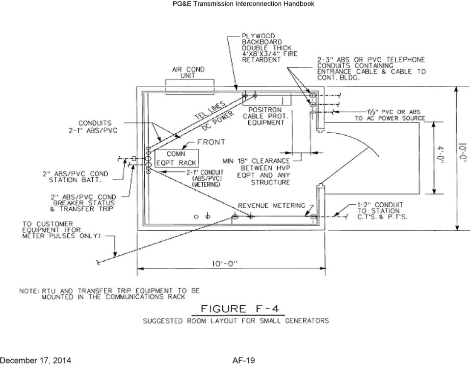
9 F2.3. Business Telephone and Revenue Metering A business telephone is required at the locations of DTT, telemetering, alarm, and metering equipment, so that maintenance and repair work can be performed efficiently. A dedicated 1MB phone line into the metering enclosure is required for the revenue meter. Where a 1MB is not available, and cellular cell signals are acceptable, the use of cellular phone is acceptable. If the revenue meter phone line cannot be dedicated to the meter, the generating or load entity shall obtain prior approval from PG&E s local metering group to arrange for a line shared switch to be used with the meter being the secondary phone user. Refer to Engineering Standard , in Appendix D of this handbook. F2.4. Environmental Considerations. PG&E must review and approve the customer s proposed equipment and room arrangement. See Figure F-4 for the typical room and conduit requirements for a small power plant. A minimum of one 71/2 foot 19-inch relay rack will be required for the teleprotection devices (Section F2.2) and RTU (Section F2.1) (this does not include the telecommunications transmission equipment (Fiber, MW, PLC, etc.). Deviations from PG&E's requirements must be approved by PG&E. Human Environment. Personnel cannot be expected to maintain and repair equipment that is located in an outdoor cabinet or in a small building, which would subject the personnel, or their test equipment to extremes in temperature and/or precipitation. In addition, 36 inches of working space must be provided in front and back of equipment that is powered by volts. Aisles must be a minimum of 36 wide. Equipment Environment. Extreme temperatures and/or excessive moisture can increase the deterioration of equipment components and wiring. Premature failure of vital protection and telemetering equipment could result in severe damage to expensive transformer banks and line conductors, as well as the loss of vital data required for efficient operation of PG&E s Transmission Operating Center and the Designated PG&E Electric Control Center. Therefore, the following requirements shall be met: The equipment room shall have an HVAC system to maintain proper environmental controls All telemetering and transfer trip equipment should be installed in environmentally controlled buildings. The HVAC system should maintain a positive air pressure differential with the surrounding areas. Temperature shall be maintained between 10 C to +30 C with a 5-95% non-condensing relative humidity Maintenance of equipment area. Typically, environmentally controlled buildings are cleaner and easier to keep clean. It should be noted that any failures of vital equipment at the customer premise due to excessive dirt could severely damage station equipment. Labor and material costs AF-9

10 for work performed to repair equipment so damaged will be billed to the Generation Entity. F.3. INSTALLATION OF LEC ENTRANCE CABLE IN SUBSTATIONS (Risk - see Section F.0. Notification) This section provides a notification as general information regarding the High Voltage Protection (HVP) issues. For proper installation and coordination with the LEC, the Generation Facility should refer to IEEE Standard 487 IEEE Recommended Practice for the Protection of Wire-Line Communication Facilities Serving Electric Supply Locations. It is extremely important that the proper cable and protection equipment be installed at substations and other high-voltage electric facilities. The main determinant is the highest expected ground potential rise (GPR). The calculated GPR value will determine what grade of telephone cable high-voltage protection equipment is required as well as the minimum dielectric strength of the cable insulating jacket. The information required to determine the GPR is as follows: Highest calculated line-to-ground fault current and the X/R value. The responsible party shall provide the information. Ground resistance (customer- provides information, after the station ground grid is installed). The Generation Entity must also provide the station ground grid area. Based on the grid area and the GPR, the responsible party will determine the estimated distance from the grid, that the sheath of the entrance telephone cable must not be grounded. This is the distance where the GPR is expected to diminish to a magnitude of 300 volts (working limit). The working limit is the voltage at which gas tube protectors can be used (except for Class A service). The LEC serving the area in which the Generation Facility is located should be contacted early (up to six months) so outside plant facilities can be engineered to serve the Generation Facility location. Failure to do this could result in the postponement of the Generation Facility s operational date and additional cost, if the entrance facility is not installed properly or the wrong materials are used. For example, entrance conduits should be non-metallic. Detailed specifications will be provided by both PG&E and the local LEC. F.4. CIRCUIT REQUIREMENTS FOR PROTECTIVE RELAYING AND EMS/SCADA CIRCUITS INSTALLED BETWEEN GENERATION FACILITY STATIONS AND PG&E POWER SUBSTATIONS (Risk - see Section F.0. Notification) This section provides a notification as general information regarding the High Voltage Protection (HVP) issues. For proper installation and coordination with the LEC, the AF-10

11 Generation Facility should refer to IEEE Standard 487 IEEE Recommended Practice for the Protection of Wire-Line Communication Facilities Serving Electric Supply Locations. The circuits requested for protective relaying purposes require that the LEC service, including entrance circuits entering the terminal sites via the protective relaying circuit dedicated entrance cable, conform to the protection standards determined by the LEC power and PG&E s responsible engineer. Certain independent telephone companies are not tariffed to provide protection equipment for the required circuits. In such a case, the Generation Entity is responsible for the purchase of the necessary protection equipment. Even if the LEC is tariffed to provide the protection equipment, the customer may decide to purchase their own high voltage equipment to save on monthly and installation charges. It should be noted that the customer is responsible for the leased circuits or alternative communication media for circuits. If PG&E personnel are requested to perform work, and it is later determined that the cause of the problem is related to the telephone line, or other customer-owned equipment, PG&E will bill the customer for the labor and travel expenses. PG&E will assist in determining the addresses for the PG&E facilities as well as confirm the circuit ordering specifications. The customer, when placing the service request, should inform the LEC that the circuit will terminate in a high voltage location and if the circuit will terminate at other high voltage locations. Special high voltage protection requirements should be reviewed by the LEC s protection department. The time required for this type of service is typically a minimum of 3-4 months. Ground potential rise data (ground resistance and ground mat area) is required by the LEC. The responsible party shall provide the maximum fault current value and the X/R value. The customer must determine if the high voltage protection equipment will be leased or owned. AF-11

12 F.5. Additional Direct Transfer Trip (DTT) Telecommunication Options The traditional metallic Class A communication configuration as described in the section F2.2 is still available to the interconnector. In addition, the following three new options are allowed, effective July 1, 2012, and are shown here: F.5.1. Option 1. All Fiber Customer Substation Outside Plant Fiber Cable T-1 Conv. Telephone Company Central Office 1 T-1 Conv. T-1 Amp Channel Bank Protection or SCADA Equipment Assorted Telephone Company Telecom Equpiment Channel Bank PG&E Substation T-1 Conv. Outside Plant Fiber Cable Telephone Company Central Office 2 T-1 Conv. T-1 Amp Protection or SCADA Equipment Protection Circuit Over All Fiber Between Substations Automatic trip upon loss of signal is not required. Manual trip may be required This solution uses fiber from PG&E s substation to the telephone company (LEC) facility to the customer s substation (no metallic connections). It provides very high speed (multiple T1 speed) and digital circuit with demultiplexing to the T1 level and uses telephone company-provided multiplexing equipment. One common version of this is a node on SONET ring. This is the preferred solution for protection-related transfer trip. The fiber routing must meet all IEEE Class A circuit requirements and must function prior to, during and after a fault on the line and equipment being protected. AF-12

13 Customer or PG&E Substation Channel Bank This configuration is the preferred option, since it provides the most reliable means of transmitting a protection trip. This configuration does not require a generator trip upon loss of carrier signal. However, to protect the system during loss of channel, PG&E may request the customer to disconnect the generator. F.5.2. Option 2. Fiber / Channelized T1 using fiber based HVP protection T-1 Conv. Outside Plant Fiber Cable T-1 Conv. Outside Plant Copper Cable Telephone Company Central Office 1 Shunt Prot. T-1 Amp Protection or SCADA Equipment Occurs outside 300V ZoI Assorted Telephone Company Telecom Equpiment PG&E Comm Facility Shunt Prot. Outside Plant Copper Cable Telephone Company Central Office 2 Shunt Prot. T-1 Amp Channel Bank Protection or SCADA Equipment Protection Circuit Over Hybrid/Copper Facilities OTT Reciever programmed to trip the generator off line for a communication fail alarm on the Third Party Provided Telco lease line. This solution uses conventional, copper T1 from the telephone company (LEC) to the 300V GPR point outside both PG&E s and the customer s substation. From the 300V GPR point, the circuit is extended using all dielectric fiber optic cable to the substation. This is a commonly used configuration to provide T1 service to cell sites that are co-located on high voltage towers. All outside plant equipment involved in this solution is to be powered from the telephone company s (LEC s) central office. The customer must ensure that the final termination at the substation also has reliable, secure, power as well. Any transfer trip circuits delivered via this method (Option 2) MUST be configured to AF-13

14 trip the generation facility s breaker when the carrier signal is lost for more than 330 milliseconds. The Generation Owner shall agree in writing that they could be subject to nuisance trips (for loss of signal) and not hold PG&E liable for claims of lost generation or other damages. This should be included in a Service Level Agreement. However, this solution is a commonly applied solution and should provide better availability and fewer trips for loss of carrier than Option 3. Customer or PG&E Substation F5.3. Option 3 - Copper / Channelized T1 using copper HVP HVP Outside Plant Copper Cable Telephone Company Central Office 1 Shunt Prot. T-1 Amp Channel Bank Protection or SCADA Equipment Cable Sheath is grounded outside 300 V ZoI (multiple) Assorted Telephone Company Telecom Equpiment Telephone Company Central Office 2 PG&E Comm Facility Shunt Prot. Outside Plant Copper Cable Shunt Prot. T-1 Amp Channel Bank Protection or SCADA Equipment Protection Circuit Over Copper Facilities OTT Reciever programmed to trip the generator off line for a communication fail alarm on the Third Party Provided Telco lease line. This is an all copper (Class B) transfer trip solution. The customer will install independent Class B T1 circuits to the customer s substation and from each of the PG&E substations (if more than one PG&E substation is involved). Each Class B circuit can trip the customer independently. This solution uses traditional T1 metallic delivery in the substation environment (Class B) and any transfer trip circuits delivered via this traditional method (Option 3) MUST be configured to AF-14

15 trip the generation facility s breaker when the carrier signal is lost for more than 330 milliseconds. The Generation Owner shall agree in writing they could be subject to nuisance trips (for loss of signal) and not hold PG&E liable for claims of lost generation or other damages. This should be included in a Service Level Agreement. F.6. Definitions B8ZS North American T1 line code, Bipolar with Eight-zero Substitution (B8ZS) Class A Non-interruptible service performance (shall function before, during, and after the power fault condition), as defined in IEEE Class B Self-restoring interruptible service performance (shall function before and after the power fault condition), as defined in IEEE Demultiplexing Separating slower speed circuits out of a higher speed circuit DS0 - Digital Signal 0 (DS0) is a basic digital signaling rate of 64 kbit/s, corresponding to the capacity of one voice-frequency-equivalent channel. The DS0 rate forms the basis for the digital multiplex transmission hierarchy in telecommunications systems used in North America. DS1 Digital Signal 1 (DS1) is a T-carrier signaling scheme with a rate of Mbit/s widely used in North America. It is a logical bit pattern used over a physical T1 line. The term is often used interchangeably with T1. DTT Direct Transfer Trip EMS Energy Management System ESF Extended Super Frame, is a standard T1 framing standard. GCC Grid Control Center GPR -- A rise in ground potential caused by a substation fault HVP -- High Voltage Protection circuitry prevents fault current from a ground potential rise from traveling on telephone cable pair to a remote ground LEC - Local Exchange Carrier, also referred to as the telephone company Multiplexing Combining several slower speed circuits into a higher speed circuit AF-15
 Class A Non-interruptible service performance (shall function before, during, and after the power fault")
16 SCADA Supervisory Control and Data Acquisition SONET -- Synchronous Optical Network one method for multiplexing and demultiplexing electrical signals onto a fiber cable T1 a multiplexed electrical signal containing 24 individual DSO channels. See DS1. TOC Transmission Operation Center AF-16

17 F.7. Figures Figure F-1 High Level 3rd party Generation Facility interconnection Items 3 rd Party IC customer is responsible for: -Providing needed infrastructure between PG&E and the CoGen Station 1) Order/Install Circuit for SCADA 2) Order/Install Circuit for EMS 3) Order/Install POTS for phone and meter 4) Order/Install Protection Circuits 5) Order/Install ECN lease for CAISO -Provide Required DC power -Provide Racks: Request installation of at least 2 for Telecom only -Order and install EMS/CAISO RIG Transmission Medium UG Fiber or OH Fiber Microwave Telco Lease(s) CLASS B SCADA CKT (customer owned) Lease Type: Class B Service Objective, Type 3, VG6, 4 wire Full Duplex, Data Circuit, 1200 Baud,with Sealing Current HVP (Service being discontinued by LEC) Interconnection Handbook Appendix F Section F5.0: Direct Transfer Trip (DTT) Telecommunications Options Alternate Option: Specified by PG&E CLASS B EMS CKT (customer owned) POTS line (customer owned) Dedicated line for Revenue Meter POTS line (customer owned) Option to Share Phone line with Revenue Meter must be approved by PG&E s local metering group PGE SCADA MODEM PGE SCADA NODE (Transmission or Distribution- Depends on the substation Co-Gen ties into) PGE EMS MODEM PGE EMS NODE LINE SHARING SWITCH Prior approval from PG&E s local metering group required to use Line Sharing switch for Revenue Meter PGE METER SCADA FEP EMS FEP PGE RTSCADA To CAISO NOTE: For Wiring, Schematic, and Arrangement Refer to PG&E Template Dwgs: , , , and Class B Ckt to Nearest PG&E SCADA node (customer owned) see Interconnection Handbook Appendix F Class B Ckt to Nearest PG&E EMS node (customer owned) May require two circutis with redundant routes PGE SCADA MODEM PGE EMS MODEM PGE RTU I/O POINTS For I/O points see PG&E Interconnection Handbook Appendix F, Section F2.1.1 Telemetering for New Generation Facilities 1,000 kw or Greater Protection to Additional Subs (if necessary) EMS Connection see Interconnection Handbook Appendix F ECN Link to CAISO (customer responsibility) CAISO MODEM Port 1 CUSTOMER OWNED RIG HVP (if lease) PGE RELAY(S) Additional PGE SUBSTATION(S) (if necessary) PGE RELAY(S) HVP (if lease) NOTE: PGE Substation Job Scope may require relay upgrades on other lines due to additional loading from Co-gen. SONET, Channel Bank, PLC, and other IT work may be associated with these system protection relay upgrades PGE SUBSTATION Transmission Medium UG Fiber or OH Fiber Microwave Telco Lease(s): Lease Type: Transfer Trip, 4 wire, 0-16 db, VG36, Service Type 4, Class A, C6 conditioning, Passive Termination, HVP (Service being discontinued by LEC) Interconnection Handbook Appendix F Section F5.0: Direct Transfer Trip (DTT) Telecommunications Options Alternate Option: Specified by Teleprotection TELEPROTECTION EQ (LINE PROTECTION) TELEPROTECTION EQ( LINE PROTECTION) [IF NECESSARY] DEMARK (TERMINAL STRIP) - PGE technician to wire teleprotectin equipment to terminal strip for components in rack -third party to wire breaker seal contact, trip ckt, and dedicated DC supply to terminal strip 3 rd Party Generation Facility Figure F-1 High Level View 3 rd Party Generation Facility Interconnection Rev. Date March, AF-17
 Lease Type: Class B Service Objective, Type 3, VG6, 4 wire Full Duplex, Data Circuit, 1200 Baud,with Sealing Current HVP (Service being discontinued by LEC) Interconnection")
18 Figure F-2 GENERATION WITH LOCKOUT RELAY TO TRANSFER TRIP UNIT (+) V DC TCO RC O 86L GENERATION FACILITY BREAKER TRIP COIL 86 L (DEDICATED) 52a or 52bx (-) V DC GENERATION FACILITY EQUIPMENT Legend: 52a Breaker seal a 52bx Breaker seal b auxiliary 86L Lockout relay AF-18

19 AF-19
CUSTOMER REQUIREMENTS AT POWER SUBSTATIONS
 CUSTOMER REQUIREMENTS AT POWER SUBSTATIONS Customer Handout Date Aug 2, 2010 Version 1.0 File Name Customer Requirements At Power Substations Document Id Outside Plant Engineering 1 Table Of Contents 1.0
6. The estimated costs here do not include any applicable ITCC tax
 General Notes and Clarifications: 1. The following estimated costs are based on past experiences and are intended to provide an order of magnitude of the total project cost given the major system components.
Teleprotection Schemes and Equipment. James W. Ebrecht Young Power Equipment Scottsdale, AZ
 * Teleprotection Schemes and Equipment James W. Ebrecht Young Power Equipment Scottsdale, AZ Teleprotection Schemes And Equipment ~ ~ Relay Relay Teleprotection Communications channel Teleprotection Protection
T1 Networking Made Easy
 T1 Networking Made Easy 1 THE T1 CARRIER 3 WHAT DOES A T1 LOOK LIKE? 3 T1 BANDWIDTH 3 T1 PHYSICAL CHARACTERISTICS 4 T1 FRAMING 5 LINE CODE 6 T1 NETWORKING 6 TELCOS 6 PSTN ACCESS WITH A T1 8 SUMMARY OF
Generation Interconnection System Impact Study Report. For. PJM Generation Interconnection Request Queue Position X1-114.
 Generation Interconnection System Impact Study Report For PJM Generation Interconnection Request Queue Position X1-114 Sandyston January 2012 Preface The intent of the System Impact Study is to determine
F2400 FOM II Series Fiber Optic Modem Technical Manual
 F2400 FOM II Series Fiber Optic Modem Technical Manual T1 Revision B Copyright April 2003 VERSITRON, Inc. 83 Albe Drive / Suite C Newark, DE 19702 www.versitron.com A030430283T PROPRIETARY DATA All data
Stand Alone POTS Fiber Optic System. P31372 Station (Subscriber) Unit P31379 Remote (Exchanger) Unit. Description & Installation
 Unit P31379 Remote (Exchanger) Unit. Description & Installation") Stand Alone POTS Fiber Optic System P31372 Station (Subscriber) Unit P31379 Remote (Exchanger) Unit Description & Installation Printed in USA 09/11 TO466 Rev. A Table of Contents Page 1.0 SCOPE 2 2.0 PRODUCT
Stand Alone POTS Fiber Optic System P31372 Station (Subscriber) Unit P31379 Remote (Exchanger) Unit Description & Installation Printed in USA 09/11 TO466 Rev. A Table of Contents Page 1.0 SCOPE 2 2.0 PRODUCT
Hyperlinks are Inactive
 Prepared by: NIB/EOB PLANNING GUIDE FOR SINGLE CUSTOMER SUBSTATIONS SERVED FROM TRANSMISSION LINES 05503 Department: Electric T&D Section: T&D Engineering and Technical Support Approved by: G.O. Duru (GOD)
Failsafe Protection for Utility Critical Infrastructure
 Failsafe Protection for Utility Critical Infrastructure Introduction PUCs maintain a crucial part of the nation s CI that provide essential services to the public, business and government. Reliable CI
Power network telecommunication
 www.siemens.com Power network telecommunication Teleprotection Answers for infrastructure and cities. Binary I/O The best protection against high-voltage grid failures When it comes to managing power networks,
ELECTRICAL ENGINEERING DESIGN CRITERIA APPENDIX F
 ELECTRICAL ENGINEERING DESIGN CRITERIA APPENDIX F TABLE OF CONTENTS Appendix F - Electrical Engineering Design Criteria F.1 Introduction...F-1 F.2 Codes and Standards...F-1 F.3 Switchyard and Transformers...F-1
RIG Acceptance Test (RAT) Procedures
 Procedures") RIG Acceptance Test (RAT) Procedures RIG Acceptance Test (RAT) Procedure 0 Print Date 2 /20/2007 REVISION HISTORY REVISON NO. DATE DESCRIPTION 1.0 Initial Release 0 Update Logo and Links i RIG Acceptance
RIG Acceptance Test (RAT) Procedures RIG Acceptance Test (RAT) Procedure 0 Print Date 2 /20/2007 REVISION HISTORY REVISON NO. DATE DESCRIPTION 1.0 Initial Release 0 Update Logo and Links i RIG Acceptance
SOLUTIONS FOR AN EVOLVING WORLD. T1/E1 and C37.94. Fiber Service Units
 SOLUTIONS FOR AN EVOLVING WORLD T1/E1 and C37.94 Fiber Service Units T1/E1 & C37.94 1 April 2013 Your world is changing and so are we. At RFL, we know your needs change much faster than your infrastructure.
Lightning Arresters P30027 18 KVA P30038 10 KVA. Description & Installation
 Lightning Arresters P30027 18 KVA P30038 10 KVA Description & Installation Printed in USA 09/11 TO330 Rev. B Table of Contents Page 1.0 SCOPE 2 2.0 PRODUCT OVERVIEW 2 2.1 Intended Uses 2 2.2 Lightning
ABB PSPS Erich Steinmann; Generator control-2013
 ABB PSPS Erich Steinmann; Generator control-2013 GENERATOR CONTROL THE MODULAR SOLUTION FOR GENERATORS To make sure that power is efficiently converted into electric energy, it is necessary to supervise
Unified requirements for systems with voltages above 1 kv up to 15 kv
 (1991) (Rev.1 May 2001) (Rev.2 July 2003) (Rev.3 Feb 2015) Unified requirements for systems with voltages above 1 kv up to 15 kv 1. General 1.1 Field of application The following requirements apply to
Introduction To SCADA and Telemetry
 Introduction To SCADA and Telemetry Joe Mullaney Senior I&C Engineer MSE Technology Applications, Inc. Tetragenics Division joe.mullaney@mse-ta.com Overview Definitions What is SCADA? What is Telemetry?
CalMod Design-Build Electrification Services
 SECTION 28 16 00 INTRUSION DETECTION SYSTEM PART 1 - GENERAL 1.1 DESCRIPTION A. This section describes the detailed technical requirements for the Intrusion Detection System (IDS), where the Contractor
OPERATIONS CAPITAL. The Operations Capital program for the test years is divided into two categories:
 Filed: September 0, 00 EB-00-0 Tab Schedule Page of OPERATIONS CAPITAL.0 INTRODUCTION Operations Capital funds enhancements and replacements to the facilities required to operate the Hydro One Transmission
APPENDIX A GENERAL DEFINITIONS & SERVICE FUNCTIONS
 APPENDIX A GENERAL DEFINITIONS & SERVICE FUNCTIONS This Appendix provides the basic definitions and service functions of local communications services under the scope of this contract. The Government requires
Title 20 PUBLIC SERVICE COMMISSION. Subtitle 50 SERVICE SUPPLIED BY ELECTRIC COMPANIES. Chapter 02 Engineering
 Title 20 PUBLIC SERVICE COMMISSION Subtitle 50 SERVICE SUPPLIED BY ELECTRIC COMPANIES Chapter 02 Engineering Authority: Public Utility Companies Article, 2-121, 5-101 and 5-303, Annotated Code of Maryland.
TL 9000 Product Categories R4.2 vs. Likely NACE Codes
 TL 9000 Product Categories R4.2 vs. Likely NACE Codes NOTE: The following list is provided as an aid in selecting NACE codes. It is not an exhaustive list of all possible NACE codes for a given TL 9000
SOLARCARE SERIES PRODUCT AND APPLICATION GUIDE
 SOLARCARE SERIES PRODUCT AND APPLICATION GUIDE for solar energy management LEATEC Delivering Solutions for Energy Management SOLAR ENERGY DATA CENTER BUILDING 4 to8 String Monitoring with 0.% Accuracy
Submit shop drawings for equipment provided under this section Shop drawings shall indicate:
 Section 16435 - SWITCHBOARDS Introduction Part 1 - General Reference The work under this section is subject to requirements of the Contract Documents including the General Conditions, Supplementary Conditions,
FIRE ALARM SYSTEM. A. Shop drawings shall be submitted as follows: 1. Manufacturer's published literature. for aspproval.
 Polk School District Specifications for the New Fire Alarm in the Existing Building Eastside Elementary School FIRE ALARM SYSTEM 1.01 SUBMITTALS A. Shop drawings shall be submitted as follows: 1. Manufacturer's
Fundamentals of Telecommunications
 Fundamentals of Telecommunications Professor of CIS Columbus, OH 43210 Jain@ACM.Org http://www.cis.ohio-state.edu/~jain/ 1 Overview Time Division Multiplexing T1, T3, DS1, E1 T1 Framing Echo Cancellation
Specification Guide. for RVAC. Direct Replacement. AC Medium Voltage. Circuit Breakers
 Specification Guide for RVAC Direct Replacement AC Medium Voltage Circuit Breakers Table of Contents 1.0 General Work Scope...3 2.0 Standards...3 3.0 Supplier Qualifications...4 4.0 Circuit Breaker Element
The following are general terms that we have found being used by tenants, landlords, IT Staff and consultants when discussing facility space.
 The following are general terms that we have found being used by tenants, landlords, IT Staff and consultants when discussing facility space. Terminology: Telco: Dmarc: NOC: SAN: GENSET: Switch: Blade
Telephone Company Lease Line Elimination. Dewey Day Principal Operational Technology Architect Pacific Gas & Electric
 Telephone Company Lease Line Elimination Dewey Day Principal Operational Technology Architect Pacific Gas & Electric Lease Line Elimination What s Happening? Telephone Companies Eliminating Lease Line
FAST TUTORIALS FOR TIME-CHALLENGED TECHNICIANS
 Tech Notes from a Telephone Engineer FAST TUTORIALS FOR TIME-CHALLENGED TECHNICIANS DDS Description: DDS Digital Data Service Long held industry acronym for transporting digital data at rates of: 2.4kbps,
Smart Solutions for Network IP Migration
 for Network IP Migration Network Access Timing and Synchronization Test & Measurement Agenda: Architectures and Topologies Product life cycle Media and Protocol Conversion Application Cases Conclusion
SCADA Controlled Multi-Step Automatic Controlled Capacitor Banks & Filter Banks
 SCADA Controlled Multi-Step Automatic Controlled Capacitor Banks & Filter Banks Introduction SCADA (Supervisory Controlled and Data Acquisition) controlled multi-step metalenclosed automatic capacitor
1.3. The network element must have the ability to be configured in a point to point, point to multi point, and daisy chain configuration.
 DESCRIPTION This work shall consist of furnishing and installing 10/100 Ethernet over Twisted Pair (TWP) Copper Modems in accordance with the contract documents and as directed by the Engineer. MATERIALS
ISIO 200. Binary Input/Output (I/O) Terminal with IEC 61850 Interface
 Terminal with IEC 61850 Interface") ISIO 200 Binary Input/Output (I/O) Terminal with IEC 61850 Interface Compact and Easy ISIO 200 Put your Binary I/Os where you need them ISIO 200 is a simple and versatile binary I/O terminal with IEC 61850
ISIO 200 Binary Input/Output (I/O) Terminal with IEC 61850 Interface Compact and Easy ISIO 200 Put your Binary I/Os where you need them ISIO 200 is a simple and versatile binary I/O terminal with IEC 61850
The Conversion Technology Experts. Media Conversion: Cost-Effectively Integrating T1 into your Fiber Network
 The Conversion Technology Experts Media Conversion: Cost-Effectively Integrating T1 into your Fiber Network Media Conversion: Cost Effectively Integrating T1 into Your Fiber Network Revealing some simple
Co-location Arrangements for Interconnecting Canadian Carriers
 COMPETITOR ACCESS TARI 2nd Revised Page 95 Cancels 1st Revised Page 95 Co-location Arrangements for Interconnecting Canadian Carriers 1. Service Description Co-location is an arrangement whereby Interconnecting
Nexus Technology Review -- Exhibit A
 Nexus Technology Review -- Exhibit A Background A. Types of DSL Lines DSL comes in many flavors: ADSL, ADSL2, ADSL2+, VDSL and VDSL2. Each DSL variant respectively operates up a higher frequency level.
INTELLIGENT DISTRIBUTION NETWORK ANALYSIS AND INFORMATION ARCHITECTURE DESIGN
 INTELLIGENT DISTRIBUTION NETWORK ANALYSIS AND INFORMATION ARCHITECTURE DESIGN Yun CHEN SMEPC,State Grid China daddygirl@126.com ABSTRACT From the background of intelligent distribution network construction,
the amount of data will grow. It is projected by the industry that utilities will go from moving and managing 7 terabytes of data to 800 terabytes.
 Before the Department of Energy Washington, D.C. 20585 In the Matter of Implementing the National Broadband Plan by Studying the Communications Requirements of Electric Utilities To Inform Federal Smart
Deployment of Telecommunications Networks
 Deployment of Telecommunications Networks Definition A telecommunications network is the combination of numerous network elements that are required to support voice, data, or video services in local or
INTERIM MARKET DOCUMENT CHANGE
 INTERIM MARKET DOCUMENT CHANGE Title: MPLS and Alternative Communications for Medium Performance Facilities File #: IESO_IMDC_0169 Version #: 0.2 Part 1 General Information Document Affected: Market Manual
ATTACHMENT G. Network Operating Agreement
 ATTACHMENT G Network Operating Agreement 1. PURPOSE OF NETWORK OPERATING AGREEMENT The purpose of this Agreement is to identify contractual requirements related to Network Integration Transmission Service
ECE 586b Course Project Report. Auto-Reclosing
 ECE 586b Course Project Report Auto-Reclosing Srichand Injeti May 5, 2008 Department Of Electrical and computer Engineering University Of Western Ontario, London Ontario Table of contents 1. Introduction...1
WIRELESS REMOTE MONITORING OF CATHODIC PROTECTION SYSTEMS. John Hawkyard MICorr Deputy General Manager Rawabi Corrosion Technology Co Ltd Al-Khobar
 WIRELESS REMOTE MONITORING OF CATHODIC PROTECTION SYSTEMS John Hawkyard MICorr Deputy General Manager Rawabi Corrosion Technology Co Ltd Al-Khobar INTRODUCTION Cathodic Protection is an electrochemical
Monitoring Underground Power Networks
 Monitoring Underground Power Networks By Mark Stiles Merve Cankaya ABSTRACT Underground electric distribution systems are common in large cities throughout the United States. Power usage for the entire
TERMS AND CONDITIONS
 Virginia Electric and Power Company TERMS AND CONDITIONS XXIV. GENERATOR INTERCONNECTION STANDARD Electric generator interconnection service includes only the ability to interconnect an electric generator
..OR How To Protect your 3-Phase Equipment Investment with 3-Phase Monitors from Time Mark...
 ..OR How To Protect your 3-Phase Equipment Investment with 3-Phase Monitors from Time Mark... TIME MARK CORPORATION 11440 EAST PINE STREET TULSA, OK 74116 USA tel 918 438-1220 fax 918 437-7584 www.time-mark.com
San Diego Gas & Electric Company FERC Order 717 Transmission Function Employee Job Descriptions August 10, 2015. Electric Grid Operations
 San Diego Gas & Electric Company FERC Order 717 Transmission Function Employee Job Descriptions August 10, 2015 Electric Grid Operations Director Electric Grid Operations: Responsible for overall transmission
T1 Backhaul Connectivity Solution All Products :: Application Note
 Telect 1 RU Customer Interface Panel (CIP) Enables Demarcation, Remote Circuit Maintenance and Trouble Isolation at the Backhaul Node The Application: T1 Demarcation and Testing in Backhaul Environments
Network Design. Yiannos Mylonas
 Network Design Yiannos Mylonas Physical Topologies There are two parts to the topology definition: the physical topology, which is the actual layout of the wire (media), and the logical topology, which
Design and Implementation of SCADA System Based Power Distribution for Primary Substation ( Monitoring System)
") Design and Implementation of SCADA System Based Power Distribution for Primary Substation ( Monitoring System) Aye Min Zaw 1, Hla Myo Tun 2 Department of Electronic Engineering, Mandalay Technological
Design and Implementation of SCADA System Based Power Distribution for Primary Substation ( Monitoring System) Aye Min Zaw 1, Hla Myo Tun 2 Department of Electronic Engineering, Mandalay Technological
Supplement No. 13 - Telephone PA P.U.C. - No. 5
 Supplement No. 13 - Telephone PA P.U.C. - No. 5 First Revised Sheet 1 Canceling Original Sheet 1 MILEAGE CHARGES EXCHANGE LINE When one-party and existing two-party line service is furnished at a point
The Industrial Wireless Book - Articles TECHNICAL ARTICLE: USING GPRS TO CONNECT SMALL, OUTLYING STATIONS
 Page 1 of 6 Print this Page Close this Window TECHNICAL ARTICLE: USING GPRS TO CONNECT SMALL, OUTLYING STATIONS Process monitoring and control for electricity distribution grids until now has been available
Colocation Scenario @ MIX
 Colocation Scenario @ MIX INTRODUCTION This white paper describes the colocation scene for ISPs interested to connect to MIX. The intended audience is network operator peering coordinators that have been
Supplement No. 83 - Telephone - PA P.U.C. No. 11. North Pittsburgh Telephone Company Section 13 Original Sheet 1 INTERCOMPANY PRIVATE LINE SERVICE
 Original Sheet 1 I. General PRIVATE LINE SERVICE A. Channels are furnished for intraexchange or interexchange service on a two-point or multi-point basis for a minimum period of one month. B. With reference
SECTION 13421 PROGRAMMABLE LOGIC CONTROLLERS AND COMPUTER CONTROL SYSTEM PART 1 GENERAL. 1.01 Summary. A. Section Includes:
 SECTION 13421 PROGRAMMABLE LOGIC CONTROLLERS AND COMPUTER CONTROL SYSTEM PART 1 GENERAL 1.01 Summary A. Section Includes: 1. The ISS shall furnish all labor, materials, equipment, services and incidentals
EECC694 - Shaaban. Transmission Channel
 The Physical Layer: Data Transmission Basics Encode data as energy at the data (information) source and transmit the encoded energy using transmitter hardware: Possible Energy Forms: Electrical, light,
PG&E Transmission Interconnection Handbook. Section L3: SUBSTATION DESIGN FOR LOAD-ONLY ENTITIES AND TRANSMISSION-ONLY ENTITIES
 Section L3: SUBSTATION DESIGN FOR LOAD-ONLY ENTITIES AND TRANSMISSION-ONLY ENTITIES PURPOSE This section provides substation design information for Load Entities interconnected at transmission voltage
The data can be transmitted through a variety of different communications platforms such as:
 COMMUNICATION NETWORK General Overview of SCADA Communications Without a properly designed communication network system, a SCADA system cannot exist. All supervisory control and data acquisition aspects
- T-Carrier Technologies -
 1 T-Carrier Fundamentals - T-Carrier Technologies - T-Carrier systems provide digitized communication for voice or data traffic across a telephone provider s network. The T-Carrier specification defines
Monthly Charge For each 1/4 mile or fraction thereof:... $1.00
 Original Sheet 1 MILEAGE CHARGES EXTENSION STATION When an extension station, bell, gong, or horn, or PBX station is located in a building separate and apart from that housing the main station, an additional
Communications Network Solutions
 Communications Network Solutions w e s tell.co m Intelligent, customized, integrated solutions CNS Solutions by Westell Infrastructure equipment and services designed to protect and support your critical
Chapter 11: WAN. Abdullah Konak School of Information Sciences and Technology Penn State Berks. Wide Area Networks (WAN)
") Chapter 11: WAN Abdullah Konak School of Information Sciences and Technology Penn State Berks Wide Area Networks (WAN) The scope of a WAN covers large geographic areas including national and international
Chapter 11: WAN Abdullah Konak School of Information Sciences and Technology Penn State Berks Wide Area Networks (WAN) The scope of a WAN covers large geographic areas including national and international
How To Test A Ds1 Signal
 T1 Installation and Maintenance INTRODUCTION T1 also known as Digital Signal level 1(DS1) is a digital technology that was created during the 1960s to carry voice and data services. The original focus
26 3213.13 Diesel Engine Driven Generators Page 1 of 6
 Last Update: December 8, 2014 A. Description of System Consultant s Handbook Page 1 of 6 1. Provide a diesel engine driven electric generating unit, factory assembled, tested and certified to operate at
Section 16935 TELEPHONE AUTOMATIC DIALER SYSTEM
 Section TELEPHONE AUTOMATIC DIALER SYSTEM PART 1 GENERAL 1.01 SYSTEM DESCRIPTION A. Design Requirements: 1. Electronic monitoring system shall interface plant alarms to public telephone system or cellular
Fundamentals of Modern Electrical Substations Part 1: Mission of Electrical Substations and their Main Components
 Fundamentals of Modern Electrical Substations Part 1: Mission of Electrical Substations and their Main Components Course No: E02-010 Credit: 2 PDH Boris Shvartsberg, Ph.D., P.E., P.M.P. Continuing Education
OPERATIONS MANUAL DATA CENTER COLOCATION
 Section I: Introduction and Service Description. OPERATIONS MANUAL DATA CENTER COLOCATION Company means MCI Communications Services, Inc., d/b/a Verizon Business Services, or any affiliated entity designated
Power products and systems. Intelligent solutions for power distribution Zone concept
 Power products and systems Intelligent solutions for power distribution Zone concept Securing continuous power supply ABB is one of the world's leading power and automation technology companies whose products,
2-Pair HDSL1 Adtran Fiber Optic Link System
 ISSUE 2 June 01, 2004 Data Sheet #37 2-Pair HDSL1 Adtran Fiber Optic Link System Contents 1. General. 1 2. Application... 2 3. Housings.. 2 4. Installation 3 5. Provisioning. 5 6. LED Indicators. 6 7.
Federal Wage System Job Grading Standards for Electric Power Controlling, 5407. Table of Contents
 Federal Wage System Job Grading Standards for Electric Power Controlling, 5407 Table of Contents WORK COVERED... 2 WORK NOT COVERED...2 TITLES... 2 GRADE LEVELS... 2 SPECIAL ADDITIONAL RESPONSIBILITIES...
CALNET 3 Subcategory 1.1 Dedicated Access. Table of Contents
 State of California IFB STPD 12-001-A CALNET 3 Subcategory 1.1 Dedicated Access Table of Contents 1.1.2.2.3 Carrier DS0 Service and Features... 1 1.1.2.3.3 Carrier DS1 Service and Features... 4 1.1.2.4.3
Schools and Libraries Universal Service Support Mechanism Eligible Services List
 Schools and Libraries Universal Service Support Mechanism Eligible Services List (WC Docket No. 13-184; CC Docket No. 02-6; GN Docket No. 09-51) The Federal Communications Commission s (FCC s) rules provide
Distributed Temperature Monitoring of Energy Transmission and Distribution Systems
 1 m 40000m0 range 61850 IEC spatial resolution Distributed Temperature Monitoring of Energy Transmission and Distribution Systems Ensuring a Reliable Supply of Electrical Power for Today s World www.en-sure.pro
San Diego Gas & Electric Company FERC Order 717 Transmission Function Employee Job Descriptions June 4, 2015. Electric Grid Operations
 San Diego Gas & Electric Company FERC Order 717 Transmission Function Employee Job Descriptions June 4, 2015 Electric Grid Operations Director Electric Grid Operations: Responsible for overall transmission
SECTION 16999 ELECTRICAL ACCEPTANCE TESTS
 SECTION 16999 ELECTRICAL ACCEPTANCE TESTS PART 1 2. AND 3. COMBINED 1.1 SUMMARY A. Description of Systems 1. Furnish all labor, materials, test equipment, and technical supervision to perform and record
ends of transmission line are used for relay operation [70]. Another type of
![ends of transmission line are used for relay operation [70]. Another type of](/thumbs/27/9771193.jpg "ends of transmission line are used for relay operation [70]. Another type of") 69 CHAPTER-4 TRANSMISSION LINE DIFFERENTIAL PROTECTION USING WIRELESS TECHNOLOGY 4.1 INTRODUCTION The probability of fault occurrence on the overhead lines is much more due to their greater lengths and
69 CHAPTER-4 TRANSMISSION LINE DIFFERENTIAL PROTECTION USING WIRELESS TECHNOLOGY 4.1 INTRODUCTION The probability of fault occurrence on the overhead lines is much more due to their greater lengths and
Business Customer Demarcation Information
 Building Industry Consulting Service (BICS) Business Customer Demarcation Information The intent of this document is to clearly define Communications terminology and deployment with reference to business
Supplement No. 75 - Telephone Pa. P.U.C. No. 5 Palmerton Telephone Section 4 Company Sixth Revised Sheet 1 Canceling Fifth Revised Sheet 1
 Supplement No. 75 - Telephone Pa. P.U.C. No. 5 Company Sixth Revised Sheet 1 Canceling Fifth Revised Sheet 1 EXTENSION STATION MILEAGE CHARGES When an extension station or wired outlet, PBX station or
Primary and Secondary Electrical Distribution Systems
 Primary and Secondary Electrical Distribution Systems Critical Facilities Round Table 12th Quarterly Membership Meeting June 2, 2006 David D. Roybal. P.E. Eaton Electrical Cutler-Hammer Products Utility
NPCC Regional Reliability Reference Directory # 8 System Restoration
 NPCC Regional Reliability Reference Directory # 8 Task Force on Coordination of Operations Revision Review Record: October 21, 2008 Adopted by the Members of the Northeast Power Coordinating Council, Inc.
Rule 5.500 Fast Track Analysis for National Life Insurance Co.
 Rule 5.500 Fast Track Analysis for National Life Insurance Co. For a 500 kw Solar array to be located at 155 Northfield Street in Montpelier, Vermont Green Mountain Power Pam Allen Date: 5/31/13 SECTION
Overview of the Telecommunications Network
 1 Overview of the Telecommunications Network 15 Telecommunication Networks 2 Basic purpose of a telecommunications network: transmit user information in any form to another user of the network. Many forms
OSIRIS Multi-Service Platform
 OSIRIS Multi-Service Platform Overview The Positron OSIRIS TM Multi-Service Platform (MSP) is an integrated access solution for the rapidly expanding optical network (SONET/SDH) broadband markets. It delivers
Chapter 2 - The TCP/IP and OSI Networking Models
 Chapter 2 - The TCP/IP and OSI Networking Models TCP/IP : Transmission Control Protocol/Internet Protocol OSI : Open System Interconnection RFC Request for Comments TCP/IP Architecture Layers Application
Suitable for Emergency, Peak and Prime Power System Applications. Low Voltage Automatic Transfer Switch Systems
 Suitable for Emergency, Peak and Prime Power System Applications Low Voltage Automatic Transfer Switch Systems THE POWER AUTHORITY THE POWER AUTHORITY ASCO s experience and commitment to excellence in
WAN. Introduction. Services used by WAN. Circuit Switched Services. Architecture of Switch Services
 WAN Introduction Wide area networks (WANs) Connect BNs and LANs across longer distances, often hundreds of miles or more Typically built by using leased circuits from common carriers such as AT&T Most
David Payne, P.E. Associate Director February 18, 2014
 David Payne, P.E. Associate Director February 18, 2014 Overview of Texas A&M University State's first public institution of higher education, was opened on Oct. 4, 1876 as the Agricultural and Mechanical
Telemetry system for cathodic protection equipment of underground metal pipelines
 RECOMMENDATION PCRA 009 June 2010 Rev. 0 Committee for Cathodic Protection and Associated Coatings Telemetry system for cathodic protection equipment of underground metal pipelines DISCLAIMER: The present
SPRINT MANAGED NETWORK SERVICES PRODUCT ANNEX ( MNS Terms and Conditions )
") SPRINT MANAGED NETWORK SERVICES PRODUCT ANNEX ( MNS Terms and Conditions ) The following terms and conditions, together with the Sprint Standard Terms and Conditions for Communication Services ( Standard
SPRINT MANAGED NETWORK SERVICES PRODUCT ANNEX ( MNS Terms and Conditions ) The following terms and conditions, together with the Sprint Standard Terms and Conditions for Communication Services ( Standard
Multiplexing. Multiplexing is the set of techniques that allows the simultaneous transmission of multiple signals across a single physical medium.
 Multiplexing Multiplexing is the set of techniques that allows the simultaneous transmission of multiple signals across a single physical medium. The following two factors in data communications lead to
TSG GUIDELINES FOR COMPUTERIZED TELEPHONE SYSTEMS TSG STANDARD 2
 TSG GUIDELINES FOR COMPUTERIZED TELEPHONE SYSTEMS TSG STANDARD 2 March 1990 PREFACE This standard was prepared by the Telephone Security Group (TSG). The charter members of the TSG are: Department of the
SECTION 13850 (28 31 00) FIRE DETECTION AND ALARM SYSTEM
 FIRE DETECTION AND ALARM SYSTEM") SECTION 13850 (28 31 00) FIRE DETECTION AND ALARM SYSTEM ENGINEERING SPECIFICATION INTELLIGENT REPORTING FIRE DETECTION SYSTEM PART 1 GENERAL 1.1 DESCRIPTION A. This specification includes the furnishing,
SECTION 13850 (28 31 00) FIRE DETECTION AND ALARM SYSTEM ENGINEERING SPECIFICATION INTELLIGENT REPORTING FIRE DETECTION SYSTEM PART 1 GENERAL 1.1 DESCRIPTION A. This specification includes the furnishing,
NXU RoIP Link to Eliminate Voice-Grade Leased Line
 NXU RoIP Link to Eliminate Voice-Grade Leased Line Purpose This Application Note will describe a method at which Network Extension Units (NXUs) can be utilized on an existing digital network to eliminate
ESP 120 M1, ESP 208 M1, ESP 240 M1, ESP 415 M1, ESP 277 M1, ESP 480 M1 and M1R variants. Installation instructions ESP M1/M1R mains protectors
 ESP 120 M1, ESP 208 M1, ESP 240 M1, ESP 415 M1, ESP 277 M1, ESP 480 M1 and M1R variants Installation instructions Contents Key points of installation Before installation Installation Installation check
Process Control and Automation using Modbus Protocol
 Process Control and Automation using Modbus Protocol Modbus is the fundamental network protocol used in most industrial applications today. It is universal, open and an easy to use protocol. Modbus has
Trip circuit supervision relay. Type RXTCS
 Trip circuit supervision relay Type RXTCS ABB a global technology leader ABB is a global leader in Power and Automation technologies that enable utility and industry customers to improve performance while
Network+ Guide to Networks 6 th Edition. Chapter 7 Wide Area Networks
 Network+ Guide to Networks 6 th Edition Chapter 7 Wide Area Networks Objectives Identify a variety of uses for WANs Explain different WAN topologies, including their advantages and disadvantages Compare
ADSL or Asymmetric Digital Subscriber Line. Backbone. Bandwidth. Bit. Bits Per Second or bps
 ADSL or Asymmetric Digital Subscriber Line Backbone Bandwidth Bit Commonly called DSL. Technology and equipment that allow high-speed communication across standard copper telephone wires. This can include