Residual Overvoltage Relay SPAU 110 C. Product Guide
|
|
|
- Christal Norton
- 9 years ago
- Views:
Transcription
1
2
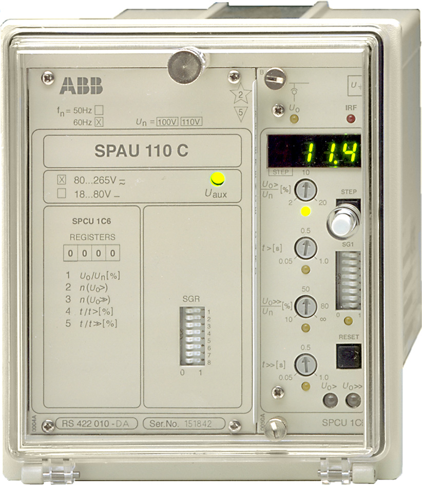
3 Issued: April 1999 Status: Updated Version: C/ Data subject to change without notice Features Definite-time residual overvoltage earthfault protection and supervision Two independent operation stages, e.g. one for signalling and the other for tripping Freely selectable output relay functions Flexible adaptation to different protection applications Numerical display of setting values, measured values, recorded fault values, indications, etc. Built-in pulse-width-modulated galvanically isolating power unit for a wide range of auxiliary voltages Serial interface for bus connection module and fibre-optic substation bus Continuous self-supervision of relay hardware and software for enhanced system reliability and availability Auto-diagnostic fault indication to facilitate repair of a permanent internal relay fault Application The residual overvoltage relay is designed to be used for earth fault protection and supervision in isolated neutral, resistance earthed or reactance earthed systems. In resonant earthed systems relay starting can be used to control the switching device of the neutral resistor. The protection relay can also be used for the earth fault protection of generators and motors and for the unbalance protection of capacitor banks. The protection relay forms an integrated protection scheme, including two-stage earth-fault protection and flexible trip and signal functions. 3
4 Design The residual overvoltage relay is a secondary relay, which is to be connected to the voltage transformers of the object to be protected. When a fault occurs, the residual overvoltage relay can be used for tripping a circuit breaker or just for signalling an earth fault, as required by the protection application. When the energizing voltage exceeds the set start value of the low-set voltage stage U 0 >, the residual overvoltage relay starts. After the set operate time t> the low-set stage operates, if the fault still persists. The high-set voltage stage operates in the same way. When the measured voltage exceeds the set start value U 0 >>, the high-set stage starts, and after the set time t>>, the high-set stage operates, if the fault still persists. Start information from the residual overvoltage relay is obtained as a contact function, which further can be used for controlling other cooperating protection relays such as neutral current measuring earth-fault relays. The relay contains one optically isolated logic input to be controlled by an external control voltage. In the residual overvoltage relay the control input is used as a blocking input. Data communication The relay is provided with a serial interface on the rear panel. By means of a bus connection module type SPA-ZC 17 or SPA-ZC 21 the relay can be connected to the fibre-optic SPA bus. The bus connection module type SPA-ZC 21 is powered from the host relay, whereas the bus connection module SPA- ZC 17 is provided with a built-in power unit, which can be fed from an external secured power source. The relay communicates with higher-level data acquisition and control systems over the SPA bus. Self-supervision The relay incorporates a sophisticated selfsupervision system with auto-diagnosis, which increases the availability of the relay and the reliability of the system. The selfsupervision system continuously monitors the hardware and the software of the relay. The system also supervises the operation of the auxiliary supply module and the voltages generated by the module. When the self-supervision system detects a permanent internal relay fault, the IRF indicator on the relay front panel is lit. At the same time the output relay of the self-supervision system operates and a fault message is transmitted to the higher-level system over the serial bus. Further, in most fault situations, a fault code is shown in the display of the protection relay module. The fault code indicates the type of the fault that has been detected. Auxiliary supply voltage The auxiliary supply of the relay is obtained from an internal plug-in type power supply module. Two auxiliary power module versions are available: type SPTU 240S1 for the supply voltage range V ac/dc and type SPTU 48S1 for the supply voltage range V dc. The power supply module forms the internal voltages required by the protection relay and the I/O module. 4
5 Technical data Table 1: Energizing inputs Terminals Rated voltage U n 100 V 110 V Continuous withstand 2 U n 2 U n Power consumption at rated voltage U n <0.5 VA Rated frequency f n, according to order 50 Hz or 60 Hz Table 2: Output contact ratings Type of contact Tripping Signalling Terminals 65-66, , , 77-78, Rated voltage Thermal withstand capability Breaking capacity for dc, when the control/signalling circuit time constant L/R 40 ms, at the control voltages 250 V ac/dc Carry continuously 5 A 5 A Make and carry for 0.5 s 30 A 10 A Make and carry for 3 s 15 A 8 A 220 V dc 1 A 0.15 A 110 V dc 3 A 0.25 A 48 V dc 5 A 1 A Table 3: Control input, communication and power supply External control input Terminals Control voltage level V dc or V ac Power consumption when input activated 2 20 ma Data communication Transmission mode Fibre-optic serial bus Data code ASCII Selectable data transfer rates 300, 1200, 2400, 4800 or 9600 Bd Fibre-optic bus for plastic fibre cables SPA-ZC 21BB connection module, for glass fibre cables SPA-ZC 21MM powered from the host relay Fibre-optic bus for plastic fibre cables SPA-ZC 17BB connection module with for glass fibre cables SPA-ZC 17MM a built-in power supply unit Auxiliary supply modules Power supply and I/O SPTU 240S V ac/dc modules and voltage SPTU 48S V dc ranges Power consumption under quiescent ~4 W conditions under operating conditions ~6 W 5
6 Technical data (cont d) Table 4: Residual overvoltage relay module SPCU 1C6 Low-set overvoltage stage U 0 > High-set overvoltage stage U 0 >> Start voltage U 0 > 2 100% of U n Start time, typically 70 ms Operate time t> s Reset time, typically 100 ms Drop-off/pick-up ratio, typically 0.96 Operate time accuracy ±2% of set value or ±40 ms Operation accuracy % of U n ±3% of set value 2 20% of U n ±5% of set value Start voltage U 0 >> 2 80% of U n and, infinite Start time, typically 70 ms Operate time t>> s Reset time, typically 100 ms Drop-off/pick-up ratio, typically 0.96 Operate time accuracy ±2% of set value or ±25 ms Operation accuracy 10 80% of U n ±3% of set value 2 16% of U n ±5% of set value Table 5: Tests and standards Test voltages Dielectric test voltage (IEC ) 2.0 kv, 50 Hz, 1 min Impulse test voltage (IEC ) 5 kv, 1.2/50 µs, 0.5 J Insulation resistance (IEC ) >100 MΩ, 500 V dc Interference tests High-frequency (1 MHz) disturbance test 2.5 kv (IEC ), common mode High-frequency (1 MHz) disturbance test 1.0 kv (IEC ), differential mode Fast transients (IEC , class III and 4 kv, 5/50 ns IEC ), power supply inputs Fast transients (IEC , class III and 2 kv, 5/50 ns IEC ), other inputs Electrostatic discharge (IEC and 8 kv IEC ), air discharge Electrostatic discharge (IEC and 6 kv IEC ,), contact discharge Environmental Service temperature range C conditions Transport and storage temperature range C (IEC ) Damp heat test (IEC ) <95%, +40 C, 96 h Relative humidity (IEC ) 93 95%, +55 C, 6 cycles Degree of protection by enclosure when panel mounted IP 54 Weight 3 kg 6
7 Block diagram Fig. 1 Block diagram and sample connection diagram BSPAU110 7
8 Mounting and dimensions Flush mounting ± ±1 Panel cutout dim100 Fig. 2 Flush-mounting relay case (dimensions in mm) Semi-flush mounting a b Raising frame SPA-ZX 111 SPA-ZX 112 SPA-ZX 113 a b SFM100_1 Fig. 3 Semi-flush mounting relay case (dimensions in mm) Mounting in 19 inch cabinets and frames An ancillary mounting plate, height 4U (~177 mm), is recommended to be used when the protection relays are to be mounted in 19 inch frames or cabinets. The ancillary mounting plate type SPA-ZX 104 accommodates three relays, type SPA-ZX 105 two relays and type SPA-ZX 106 one relay. Projecting mounting When projecting mounting is preferred, a relay case type SPA-ZX 110 is used. The relay case for projecting mounting is provided with front connectors. SPA-ZX104 SPA-ZX105 SPA-ZX106 +0,4 482,6 0 (19") SPA-ZX110 SPA-ZX ø ,6 21,5 7 +0, (4U) _6_10 Fig. 4 Mounting cabinets and frames as well as projecting mounting (dimensions in mm) 8
9 Ordering When ordering, please specify: Ordering information Ordering example 1. Type designation and quantity, 5 pieces 2. Order number RS AA 3. Rated values U n =110 V, f n =50 Hz 4. Auxiliary voltage U aux =110 V dc 5. Accessories - 6. Special requirements - Order numbers Residual overvoltage relay without test adapter Residual overvoltage relay including test adapter RTXP 18 The last two letters of the order number indicate the rated frequency f n and the auxiliary voltage U aux of the relay as follows: RS AA, CA, DA, FA RS AA, CA, DA, FA AA equals f n = 50 Hz and U aux = V ac/dc CA equals f n = 50 Hz and U aux = V dc DA equals f n = 60 Hz and U aux = V ac/dc FA equals f n = 60 Hz and U aux = V dc References Additional information Manual Residual overvoltage relay 1MRS MUM EN 9
10 ABB Oy Distribution Automation P.O. Box 699 FI Vaasa, FINLAND Tel Fax
Voltage Regulator SPAU 341 C. Product Guide
 Issued: July 1998 Status: Updated Version: D/25.04.2006 Data subject to change without notice Features Comprehensive voltage regulation for power transformers with on-load tapchangers in distribution substations
Capacitor Protection Relay SPAJ 160 C. Product Guide
 Issued: April 1999 Status: Updated Version: C/19.04.2006 Data subject to change without notice Features One-, two- and three-phase overload stage with definite time characteristic One-, two- and three-phase
Disturbance Recoder SPCR 8C27. Product Guide
 Issued: April 1999 Status: Updated Version: C/26.04.2006 Data subject to change without notice Features Versatile digital disturbance recorder module for recording various phenomena in the electric power
Remote Monitoring and REC 501 Control Unit Product Guide
 Remote Monitoring and Control Unit REC 501 Product Guide Issued: May 1999 Status: Updated Version: B/06.11.2001 Data subject to change without notice Features Remote control and monitoring unit for the
Current and voltage measuring relays
 Current and voltage measuring relays RXIK 1, RXEEB 1 and Page 1 Issued June 1999 Changed since July 1998 Data subject to change without notice RXIK 1 RXEEB 1 (SE980082) (SE980081) (SE970869) Features Application
Trip circuit supervision relay. Type RXTCS
 Trip circuit supervision relay Type RXTCS ABB a global technology leader ABB is a global leader in Power and Automation technologies that enable utility and industry customers to improve performance while
Waveguide Access Point WGA631. Product Guide
 Waveguide Access Point Product Guide Waveguide Access Point Contents 1. Description............................ 3 2. Application............................ 3 3. Technical data... 4 4. Physical interfaces......................
Circulating Current Relay. Type IRXm
 Circulating Current Relay Type IRXm ABB a global technology leader ABB is a global leader in Power and Automation technologies that enable utility and industry customers to improve performance while lowering
Quick Connect. quick - simple - efficient. www.g-mw.de
 Quick Connect quick - simple - efficient www.g-mw.de Phone: +49 9103 7129-0 Fax: +49 9103 7129-207 Innovative connection technology to plug three single-phase current transformers to multifunctional power
Relion 605 series. Self-powered feeder protection REJ603 Product Guide
 Relion 605 series Relion 605 series Relion 605 series Self-powered feeder protection Product Guide Product version: 3.0 Contents 1.... 3 2. Relay functions... 3 3. Protection functions... 4 4. Application...
Arc Protection Relay REA 10_. Product Guide
 Arc Protection Relay REA 10_ Product Guide Issued: 1May 1999 Status: Updated Version: D / 22.06.2005 Data subject to change without notice Features Loop-type sensor fiber, radial sensor fiber or lens-type
Safety technique. Emergency stop module BO 5988 safemaster
 Safety technique Emergency stop module BO 5988 safemaster 0221562 Function diagram Pushbutton on Mains or emergencystop () K1 According to EC Directive for machines 98/37/EG According to IEC/E 60204-1
RM4TG20 three-phase network control relay RM4-T - range 200..500 V
 Characteristics three-phase network control relay RM4-T - range 200..500 V Complementary [Us] rated supply voltage Output contacts Setting accuracy of time delay Delay at power up Measuring cycle Marking
Electronic timer CT-AHD.12 OFF-delayed with 1 c/o (SPDT) contact
 contact") Data sheet Electronic timer CT-AHD.12 OFF-delayed with 1 c/o (SPDT) contact The CT-AHD.12 is an electronic time relay with OFF-delay. It is from the CT-D range. With their MDRC profile and a width of only
Data sheet Electronic timer CT-AHD.12 OFF-delayed with 1 c/o (SPDT) contact The CT-AHD.12 is an electronic time relay with OFF-delay. It is from the CT-D range. With their MDRC profile and a width of only
Pilot-wire differential relay for lines with two or more terminals
 Pilot-wire differential relay for lines with two or more terminals Page 1 Issued: March 2003 Revision: A Data subject to change without notice Pilot-wire differential relay with RXHL 401 Features Phase
Three-phase monitoring relay CM-PFE
 Data sheet Three-phase monitoring relay CM-PFE The CM-PFE is a three-phase monitoring relay that monitors the phase parameter phase sequence and phase failure in three-phase mains. 2CDC 251 005 S0012 Characteristics
Electronic timer CT-VBS.17+18 OFF-delayed without auxiliary voltage, for DC contactors Data sheet
 Characteristics Single-function OFF-delay timer for DC contactors, without auxiliary voltage Width.5 mm CDC 5 6 F3 Approvals A culus E CCC CT-VBS a Circuit diagram b Marker label Marks a CE b C-Tick Order
Features. Display. Measurements. Intelligent. Accuracy. Models. Installation DEIF A/S. Multi-instrument 4921210109D
 7000/7000C/7020 Multi-instrument 4921210109D Features Measurements All 3-phase AC measurements True RMS Replaces analogue meters Demand on each phase current Accuracy U, I and F class 0.5 Other values
Combined overcurrent & earth-fault relay. Type SPAJ 140 C
 Combined overcurrent & earth-fault relay Type SPAJ 140 C ABB a global technology leader ABB is a global leader in Power and Automation technologies that enable utility and industry customers to improve
Low Voltage Products. Switches Automatic Transfer Switches
 Low Voltage Products Switches Automatic Transfer Switches Growing importance of a secure power supply Standby power is an integral part of many industrial and domestic electrical systems. High energy prices,
38 Series - Relay interface modules 0.1-2 - 3-5 - 6-8 A
 38 Series - Relay interface modules 0.1-2 - 3-5 - 6-8 A Common features Instant ejection of relay by plastic retaining clip Integral coil indication and protection circuit EMR Electromechanical Relays
RM17TE 183...528 V AC. Main. Product or component type. Product specific application. Relay monitored parameters 250 V DC 5 A DC
 Characteristics multifunction control relay RM17-TE - range 183..528 V AC Complementary Reset time Maximum switching voltage Minimum switching current Maximum switching current [Us] rated supply voltage
Type: EASY719 DC RC Article No.: 274119. Ordering information Relay outputs Quantity 6 Power supply V DC 24 V DC. Description
 Type: EASY719 DC RC Article.: 274119 Ordering information Relay outputs Quantity 6 Power supply V DC 24 V DC Description 12 digital inputs (4 inputs available as analog inputs) 6 relay outputs LCD display
REA 10_ 1MRS 750929-MBG
 Arc protection relay REA 10_ Issued: May 1999 Status: Updated Version: C/05.07.2002 Data subject to change without notice Features Loop-type sensor fibre, radial sensor fibre or lens-type sensor for arc
Your Advantages For safety application up to PL e / Cat. 4 e.g. SIL 3 Manual or automatic start 0225592. * see variants. Applications.
 Safety Technique SAFEMASTER Emergency Stop Module BG 5924, IP 5924 Your Advantages For safety application up to PL e / Cat. 4 e.g. SIL 3 Manual or automatic start 0225592 BG 5924 IP 5924 Product Description
MasterINTERFACE 39 Series - Relay interface modules
 MasterINTERFACE 39 Series - Relay interface modules Common features Space saving 6.2 mm wide Connections for 16-way jumper link Integral coil indication and protection circuit Secure retention and easy
Positive-guided relay outputs: 3 safety contacts (N/O), instantaneous. 1 auxiliary contact (N/C), instantaneous
, instantaneous. 1 auxiliary contact (N/C), instantaneous") Safety relay for monitoring E-STOP pushbuttons. Approvals Unit features Positive-guided relay outputs: 3 safety contacts (N/O), instantaneous 1 auxiliary contact (N/C), instantaneous Safe separation of
Safety relay for monitoring E-STOP pushbuttons. Approvals Unit features Positive-guided relay outputs: 3 safety contacts (N/O), instantaneous 1 auxiliary contact (N/C), instantaneous Safe separation of
Bulletin 150 Smart Motor Controllers SMC-3 Smart Motor Controller
 Overview/Modes of Operation Bulletin 150 Smart Motor Controller The SMC-3 is a compact, simple to use, solid-state motor controller designed to operate 3-phase motors. It features a built-in overload relay
Substation Automation Products Relion 670/650 series IEC and ANSI Hardware
 Substation Automation Products Relion 670/650 series IEC and ANSI Hardware ABB Group 1MRG014097 October 2013 Relion 670/650 series hardware Contents Relion 670/650 series Relion Hardware Relion Common
ABB 1. Three-phase monitoring relay CM-PFS. Data sheet. Features. Approvals. Marks. Order data. Order data - Accessories. Application.
 1SR 430 824 F9300 Features Monitoring of three-phase mains for phase sequence and failure Powered by the measuring circuit 2 c/o (SPDT) contacts 1 LED for status indication Approvals R: yellow LED - relay
Single-phase (220...240 V) voltage monitoring: Undervoltage Overvoltage Window mode (overvoltage + undervoltage) Voltage fault memory selectable
 voltage monitoring: Undervoltage Overvoltage Window mode (overvoltage + undervoltage) Voltage fault memory selectable") Features 70.11 70.31 70.41 Electronic voltage monitoring relays for single and three-phase applications Multifunctional types, providing the flexibility of monitoring Undervoltage, Overvoltage, Window
Features 70.11 70.31 70.41 Electronic voltage monitoring relays for single and three-phase applications Multifunctional types, providing the flexibility of monitoring Undervoltage, Overvoltage, Window
38 Series - Relay interface modules 0.1-2 - 3-5 - 6-8 - 16 A
 38 Series - Relay interface modules 0.1-2 - 3-5 - 6-8 - 16 A 38 SERIES Common features Instant ejection of relay by plastic retaining clip Integral coil indication and protection circuit EMR Electromechanical
T 3000. Substation Maintenance and Commissioning Test Equipment
 T 3000 Substation Maintenance and Commissioning Test Equipment Multi function system for testing substation equipment such as: current, voltage and power transformers, all type of protection relays, energy
Rack mounted telephone- and leased line modem for industrial applications
 Rack mounted telephone- and leased line modem for industrial applications TR-6 Rack modem for industrial PSTNand /-wire leased line applications The TR-6 is an analogue V. 9 -rack PSTN modem as well as
38 SERIES. Relay interface modules 0.1-2 - 3-5 - 6-8 - 16 A. EMR Electromechanical Relays. Common features. SSR Solid State Relays. 6.
 38 Relay interface modules 0.1-2 - 3-5 - 6-8 - 16 A 38 Common features Instant ejection of relay by plastic retaining clip Integral coil indication and protection circuit 6.2 mm wide EMR - DC, AC or AC/DC
MasterINTERFACE 39 Series - Relay interface modules
 MasterINTERFACE 39 Series - 39 Common features Space saving 6.2 mm wide Connections for 16-way jumper link Integral coil indication and protection circuit Secure retention and easy ejection by plastic
ISL Insulation monitoring devices Continuous monitoring of IT systems from photovoltaic to industrial applications.
 ISL Insulation monitoring devices Continuous monitoring of IT systems from photovoltaic to industrial applications. Ensuring operational continuity To ensure the operational continuity of an electrical
REA 101 Arc protection relay. Operator s manual
 REA 101 1MRS 751003-MUM Issued: 08.04.1998 Version: C/19.10.2000 Checked: Approved: REA 101 We reserve the right to change data without prior notice. Contents: 1. General...5 1.1. Features...5 2. Safety...6
E-STOP relays, safety gate monitors
 Unit features Safety features Gertebild ][Bildunterschrift_NOT_Sch.tuer_Licht Safety relay for monitoring E-STOP pushbuttons, safety gates and light beam devices Approvals Gertemerkmale Positive-guided
Both variants can be used for measuring the positive sequence voltage Up or the negative sequence voltage Un.
 Rev. - 2004-10-22 Page 1(5) General RXTBA 1 is a three-phase phase sequence voltage filter built up by resistors and capacitors. The filter is available in two voltage variants; one for rated voltage 3x110
Relion 605 series. Feeder protection and control / Feeder protection REF601 / REJ601 Product Guide
 Relion 605 series Feeder protection and control / Feeder protection Product Guide Product version: 2.2FP1 Contents 1. Description... 3 2. Relay functions... 3 3. Protection functions... 4 4. Application...
Circuit Breaker LTB D with Motor Drive. Motor Drive. ABB PP/H/HV - Page 1. Ed 2006-04
 Circuit Breaker LTB D with Motor Drive Motor Drive ABB PP/H/HV - Page 1 Ed 2006-04 Technology Traditional technology Traditional spring operating mechanism: Closing mechanism ABB PP/H/HV - Page 2 Tripping
DRTS 33. The new generation of advanced test equipments for Relays, Energy meters, Transducers and Power quality meters
 The new generation of advanced test equipments for Relays, Energy meters, Transducers and Power quality meters Testing all relay technologies: electromechanical, solid state, numerical and IEC61850 Manual
Pluggable interface relays CR-P Pcb relays
 2CDC 293 034 F0004 1 2 4 3 Features 9 different supply s: DC versions: 12 V, 24 V, 48 V, 110 V AC versions: 24 V, 48 V, 110 V, 120 V, 230 V Output contacts: 1 c/o (16 A) or 2 c/o (8 A) Cadmium-free contact
RISH EM 3490 DS Dual Source Energy Meter RISH EM 3490 DS. Application : Product Features:
 Application : RISH Master 3490 DS measures important electrical parameters of Utility (in normal mode) & Generators (in Power back up) in three phase and single phase Network & replaces the multiple analog
Data sheet GIOD.1 Input/output module with CAN bus. ERP no.: 5204183. www.guentner.de. Data sheet GIOD.1 V_3.0
 Data sheet GIOD.1 Input/output module with CAN bus ERP no.: 5204183 www.guentner.de Page 2 / 10 Contents 1 GIOD.1... 3 1.1 Functional description...3 1.2 Connections... 5 1.3 Electrical properties of...
Thermistor motor protection relays CM-MSS.22 and CM-MSS.23
 Data sheet Thermistor motor protection relays CM-MSS.22 and CM-MSS.23 The thermistor motor protection relays CM-MSS.22 and CM-MSS.23 monitor the winding temperature of motors and protect them from overheating,
Power Meter Series 700
 PowerLogic power-monitoring units Power Meter Series 700 Technical data sheet 2007 Functions and characteristics E90463 The PowerLogic Power Meter Series 700 offers all the measurement capabilities required
PNOZsigma - Base units
 PNOZsigma - Base units Register Login Sensors Control and Communication Electronic monitoring relays Safety Relays PNOZ X PNOZsigma PNOZelog PNOZmulti PNOZpower Configurable control systems Programmable
ABB Drives. User s Manual. Pulse Encoder Interface Module RTAC-01
 ABB Drives User s Manual Pulse Encoder Interface Module RTAC-0 Pulse Encoder Interface Module RTAC-0 User s Manual 3AFE 64486853 REV A EN EFFECTIVE:.5.00 00 ABB Oy. All Rights Reserved. Safety instructions
Voltage monitoring relays CM-ESS.2 For single-phase AC/DC voltages
 Data sheet Voltage monitoring relays CM-ESS.2 For single-phase AC/DC voltages The CM-ESS.2 is an electronic voltage monitoring relay that provides reliable monitoring of voltages as well as detection of
TRACTION NETWORK MONITORING AND PROTECTION SYSTEM SMTN-3 CITY ELECTRIC TRANSPORT RAILWAYS METRO INDUSTRY
 TRACTION NETWORK MONITORING AND PROTECTION SYSTEM SMTN-3 CITY ELECTRIC TRANSPORT RAILWAYS METRO INDUSTRY 2 TRACTION NETWORK MONITORING AND PROTECTION SYSTEM Traction network monitoring and protection system,
Telephone- and leased line modem for industrial applications TD-36
 Telephone- and leased line modem for industrial applications TD-36 Modem for industrial PSTN- and leased line applications The TD-36 is an analogue V.34 PSTN modem as well as an industrial 2-wire leased
PD30ETB20xxIS. Photoelectrics, Background Suppression reflective with IR light. Main features. Description
 Photoelectrics, Background Suppression reflective with IR light Main features Description The PD30ET... stainless steel sensors are built with high-quality materials and designed for harsh environments.
Arc Protection Relay REA 101. Operator s Manual
 Arc Protection Relay 1MRS751003-MUM Issued: 08.04.1998 Version: F/23.06.2005 Arc Protection Relay 1. About this manual...5 1.1. Copyrights...5 1.2. Trademarks...5 1.3. Guarantee...5 1.4. General...5 1.5.
ELR: ABB range of front panel residual current relays Protection device according to IEC/EN 60947-2 Annex M
 ELR: ABB range of front panel residual current relays Protection device according to IEC/EN 60947-2 Annex M Tested, certified, reliable Network monitoring and protection The electronic residual current
Type: DILM115(RAC240) Article No.: 239548 Sales text Contactor,55kW/400V,AC operated. Ordering information
 Article No.: 239548 Sales text Contactor,55kW/400V,AC operated. Ordering information") Type: DILM115(RAC240) Article No.: 239548 Sales text Contactor,55kW/400V,AC operated Ordering information Connection technique Description Description Rated operational current Screw terminals 3 pole AC
Type: DILM115(RAC240) Article No.: 239548 Sales text Contactor,55kW/400V,AC operated Ordering information Connection technique Description Description Rated operational current Screw terminals 3 pole AC
48 SERIES Relay interface modules 10 A
 48 Relay interface modules 10 A 1 CO relay interface modules, mm wide Ideal interface for PLC and electronic systems Type 48.P3 1 CO 10 A s Type 48.31 1 CO 10 A s AC coils or DC sensitive coils Supply
ISIO 200. Binary Input/Output (I/O) Terminal with IEC 61850 Interface
 Terminal with IEC 61850 Interface") ISIO 200 Binary Input/Output (I/O) Terminal with IEC 61850 Interface Compact and Easy ISIO 200 Put your Binary I/Os where you need them ISIO 200 is a simple and versatile binary I/O terminal with IEC 61850
ISIO 200 Binary Input/Output (I/O) Terminal with IEC 61850 Interface Compact and Easy ISIO 200 Put your Binary I/Os where you need them ISIO 200 is a simple and versatile binary I/O terminal with IEC 61850
Electronic overload relay EF65, EF96 and EF146
 Data sheet Electronic overload relay EF65, EF96 and EF146 Electronic overload relays offer reliable protection in case of overload and phase-failure. They are the alternative to thermal overload relays.
RISH CON - Hz. Salient Features : Application : Product Features: FREQUENCY TRANSDUCER
 Application : The RISH CON - Hz transducer is used for frequency measurement. The output signal is proportional to measured frequency and is either load independent DC Current or load independent DC Voltage.
Power-monitoring unit PowerLogic System. Technical data sheet. Power Meter Series 800
 Power-monitoring unit PowerLogic System Technical data sheet 2003 Power Meter Series 800 Function and characteristics PB100313 The PowerLogic Power Meter Series 800 offers all the high-performance measurement
Electronic overload relay EF19 and EF45
 Data sheet Electronic overload relay EF19 and EF45 Electronic overload relays offer reliable protection in case of overload and phase-failure. They are the alternative to thermal overload relays. Motor
RM35UA13MW. range 15..600 V. Main. Product or component type. Relay monitored parameters
 Characteristics multifunction voltage control relay RM35-U - range 15..600 V Complementary Reset time Maximum switching voltage [Us] rated supply voltage Supply voltage limits Power consumption in W Main
Voltage monitoring relays CM-ESS.M For single-phase AC/DC voltages
 Data sheet Voltage monitoring relays CM-ESS.M For single-phase AC/DC voltages The CM-ESS.M is an electronic voltage monitoring relay that provides reliable monitoring of voltages as well as detection of
H/L = Power supply. FN = Nominal Frequency. RN = Rated value of output burden. UN = Nominal input voltage. IN = Nominal input current.
 Application : The transducer RISH CON - CA/CV (Fig.1) converts a sinusoidal AC Current or AC Voltage into a load independent DC Current or a load independent DC Voltage proportional to the measured value.
Digital Pressure Measuring Instrument MDR480
 Description The digital panel instrument MDR480 is designed to measure, display, and monitor pressures in industrial applications. The instrument is panel mounted with a front frame dimension of 96 mm
ALARM ANNUNCIATOR ME - 3010 INSTRUCTION MANUAL
 ALARM ANNUNCIATOR ME - 3010 INSTRUCTION MANUAL INTRODUCTION... 2.. TECHNICAL DATA... 3 ACCESSORIES... 5. INSTALLATION... 7 OPERATION... 12. TECHNICAL INFORMATION... 13 MAINTENANCE... 14. CONFIGURATIONS...
Automation System TROVIS 6400 TROVIS 6493 Compact Controller
 Automation System TROVIS 6400 TROVIS 6493 Compact Controller For panel mounting (front frame 48 x 96 mm/1.89 x 3.78 inch) Application Digital controller to automate industrial and process plants for general
VEO. V4PF480Y/277VSYTK02 Art.Nr.: 2104200. V4PF480Y/277VSYTK02P Art.Nr.: 2104210 TECHNICAL DATA
 Monitoring of phase sequence and phase loss Monitoring of asymmetry Temperature monitoring (PTC) Supply voltage 208-480 V AC Supply circuit = measuring circuit 2 change-over contacts Width 45 mm Control
Analog signal converters CC-E I/I Current / current isolators
 ata sheet Analog signal converters CC-E I/I Current / current isolators The CC-E I/I is an isolator for the electrical isolation of current signals without auxiliary supply. It allows the isolation between
KOLMA and IHDA Indoor type Cable Current Transformers Catalogue ABB Power Distribution ABB Transmit 1 KKOLMA 1 GB
 KOLMA and IHDA Indoor type Cable Current Transformers Catalogue ABB Power Distribution ABB Transmit 1 KKOLMA 1 GB KOLMA and IHDA Indoor Type Cable Current Transformers Index Description... 3 Technical
Thermistor motor protection
 Thermistor motor protection CM-E Range Thermistor motor protection Thermistor motor protection relays Benefits and advantages Selection table Operating principle and fields of application for thermistor
Current valve. for AC 24 V pulse/pause control of electrical loads up to 30 kw
 4 937 DESIO Current valve for AC 24 V pulse/pause control of electrical loads up to 30 kw SEA45.1 Use The current valve is used for the control of electric heating elements in heating, ventilation and
Contact expansion modules
 Gertebild ][Bildunterschrift Kontakterweiterungen Contact for increasing the number of available contacts Approvals Zulassungen Unit features Gertemerkmale Positive-guided relay outputs: 4 safety contacts
HSP GmbH Zum Handwerkerhof 2 90530 Wendelstein Tel. 09129 / 2852-0 Fax: 09129 / 2852-11 Web: www.hsshsp.de EMAIL: [email protected] NTG-3000.
 NTG-3000 Transducer Data Sheet Document Version 2.8 Page 1 of 10 Versions / Revisions: Document Creation Author Description version date 2.0 2012-07-25 P. Compensis First official version 2.1 2012-08-24
Permissible ambient temperature Operation Storage, transport
 The Sitras PRO combined DC protective unit and controller is used in the power supply for DC railways in mass transit and main-line systems up 3,000 V DC. It protects DC switch gear and contact line systems
Maximum Demand Control
 Maximum Demand Control There are three terms that appear on the majority of electric company bills: Active energy consumption (kwh) Reactive energy consumption (kvarh) Maximum Demand Traditionally, utility
ABB 1 NEW. Three-phase monitoring relay for grid feeding CM-UFS.1. Data sheet. Features. Approvals. Marks. Order data. Order data - Accessories
 2CDC 251 014 F0t09 Features Monitoring of three-phase mains for grid feeding Type-tested in accordance with DIN V VDE V 0126-1-1: February 2006 Neutral conductor connection configurable Can also be used
Temperature monitoring relays CM-TCS Monitoring relays for monitoring temperatures with a PT100 sensor (2- or 3-wire connection)
") Data sheet Temperature monitoring relays CM-TCS Monitoring relays for monitoring temperatures with a PT100 sensor (2- or 3-wire connection) The temperature monitoring relays CM-TCS monitor overtemperature,
Data sheet Temperature monitoring relays CM-TCS Monitoring relays for monitoring temperatures with a PT100 sensor (2- or 3-wire connection) The temperature monitoring relays CM-TCS monitor overtemperature,
Inductive Sensors Single or Dual Loop Detectors Type LD with teach-in
 Inductive Sensors Single or Dual Loop Detectors Type LD with teach-in Single or Dual loop detector Automatically adjustment of detection level Manual sensitivity for compensations of variations Easy installation
Safety Relays ESM/ESM-F
 Safety Relays ESM/ESM-F More than safety. Safety More than safety. Emil Euchner, the company s founder and inventor of the multiple limit switch, circa 1928. Around the world the Swabian specialists in
Bulletin 150 SMC Flex Smart Motor Controller Specifications
 Specifications Specifications Standard Features Optional Features Installation Setup Communications Power Wiring Control Wiring Keypad Software Starting and Stopping Modes Protection and Diagnostics Metering
Voltage monitoring relays CM-ESS.2 For single-phase AC/DC voltages
 Data sheet Voltage monitoring relays CM-ESS.2 For single-phase AC/DC voltages The CM-ESS.2 is an electronic voltage monitoring relay that provides reliable monitoring of voltages as well as detection of
Product Information Sheet UH36 Hi Pot Tester
 Product Information Sheet UH36 ETL Prüftechnik GmbH Telefon: +49 711 83 99 39-0 E-Mail: [email protected] Carl-Peters-Straße 23 D-70825 Korntal-Münchingen Telefax: +49 711 83 99 39-9 Internet: www.etl-prueftechnik.de
R.C.C.B. s two-pole LEXIC
 87045 LIMOGES Cedex Telephone : (+33) 05 55 06 87 87 Fax : (+ 33) 05 55 06 88 88 R.C.C.B. s two-pole LEXIC 089 06/09/10/11/12/15/16/17/18/ 27/28/29/30/35, CONTENTS PAGES 1. Electrical and mechanical characteristics...
80 Series - Modular timers 16 A. Features 80.01 80.11
 80 Series - Modular timers 16 A Features 80.11 Multi-function and mono-function timer range - Multi-function & multi-voltage 80.11 - On-delay, multi-voltage 17.5 mm wide Six time scales from 0.1s to 24h
Pressure monitoring equipment for oil-sf 6. bushings, type GOEK
 Pressure monitoring equipment for oil-sf 6 bushings, type GOEK Installation and maintenance guide 5693 827-6 en, Rev. 3, 2002-01-30 This document must not be copied without our written permission, and
Relion. Power system protection and automation reference Extending substation life cycle with IEC 61850
 Relion Power system protection and automation reference Extending substation life cycle with IEC 61850 Extending substation life cycle with IEC 61850 A step-by-step power system retrofit approach for optimizing
Panel Meters and Controllers Modular Panel Meter Type EDM 35
 Panel Meters and Controllers Modular Panel Meter Type EDM 35 Modular digital panel meter, 3 1/2-digit Indicating or controlling current, voltage, resistance, temperature, tacho or frequency. Easy programming
JNIOR. Overview. Get Connected. Get Results. JNIOR Model 310. JNIOR Model 312. JNIOR Model 314. JNIOR Model 410
 The INTEG is an Ethernet I/O (digital, analog) device that monitors and controls a small set of process signals. functions as both basic I/O for integration with another application or system AND as a
AS-i 3.0 Gateways, PROFIsafe via PROFIBUS or PROFINET
 safe via BUS or NET AS-i 3.0 Gateways, safe via NET or BUS safe and Safe Link in one device up to 450 devices 2 / 1 Master, NET / BUS Slave AS-i Safety input slaves report via safe AS-i Safety output slaves
Brake module AX5021. Documentation. Please read this document carefully before installing and commissioning the brake module!
 Documentation Brake module AX5021 Please read this document carefully before installing and commissioning the brake module! Version : 1.2 : 2012.03.05 Date Article-no. : TDmlAX-5021-0000-0200 Page 2/8
Contact expander modules
 Gertebild ][Bildunterschrift Kontakterweiterungen Contact expansion module for increasing the number of available contacts Approvals Zulassungen Unit features Gertemerkmale Positive-guided relay outputs:
Type: DILM32 10(24V50HZ) Article No.: 277247
 Article No.: 277247") Type: DILM32 10(24V50HZ) Article No.: 277247 Ordering information Rated operational current AC 3 400 V I e A 32 Max. rating for three phase motors, 50 60 Hz AC 3 230 V Max. rating for three phase motors,
Type: DILM32 10(24V50HZ) Article No.: 277247 Ordering information Rated operational current AC 3 400 V I e A 32 Max. rating for three phase motors, 50 60 Hz AC 3 230 V Max. rating for three phase motors,
49 Series - Relay interface modules 8-10 - 16 A. Features
 Features 1 & 2 Pole relay interface modules 5 µm Gold plate contacts for low level switching capability 49.31-50x0-1 Pole 10 A (screw terminal) 49.52-50x0-2 Pole 8 A (screw terminal) 49.72-50x0-2 Pole
MILLENIUM INSTALLATION MANUAL NTR 735 A. Simple Automation Control Module (MAS)
") MILLENIUM Table of contents 1. INTRODUCTION 1 2. HARDWARE DESCRIPTION 2 3. INSTALLATION 5 4. CONNECTION 6 5. USER SAFETY AND PROTECTION OF EQUIPMENT 8 1. Introduction The MILLENIUM series has been designed
MILLENIUM Table of contents 1. INTRODUCTION 1 2. HARDWARE DESCRIPTION 2 3. INSTALLATION 5 4. CONNECTION 6 5. USER SAFETY AND PROTECTION OF EQUIPMENT 8 1. Introduction The MILLENIUM series has been designed
ABB Drives. User s Manual HTL Encoder Interface FEN-31
 ABB Drives User s Manual HTL Encoder Interface FEN-31 HTL Encoder Interface FEN-31 User s Manual 3AUA0000031044 Rev B EN EFFECTIVE: 2010-04-06 2010 ABB Oy. All Rights Reserved. 5 Safety instructions
Installation manual. Generator Paralleling Controller GPC multi-line 2 4189340225C
 Installation manual Generator Paralleling Controller GPC multi-line 2 Software ver. 1.3X Compact system in one unit - dynamic synchronisation - load sharing - generator protection DEIF A/S 3-phase AC RMS
SURGE PROTECTIVE DEVICES
 SURGE PROTECTIVE DEVICES 1. INTRODUCTION In order to ensure safety of people, protection of equipment and, to a certain extent, continuity of supply, insulation co-ordination aims at reducing the likelihood