IC-W1. WiFi Irrigation Controller. User Manual and Installation Instructions
|
|
|
- Bridget Turner
- 9 years ago
- Views:
Transcription

1 IC-W1 WiFi Irrigation Controller User Manual and Installation Instructions
2 IRRIGATIONCADDY MODEL: IC- W 1 User Manual and Installation Instructions KGControls LLC 2606 Orsobello Place Cedar Park, TX USA [email protected] i
3 Table of Contents Installation... 4 Introduction 4 Features 4 Installation Steps 4 Steps:...5 Mounting on the Wall 5 Connecting Valve Wires 6 Steps:...6 Connecting to the Network 6 Steps:...6 Connecting Expansion Modules 15 Reset to factory defaults 16 Usage Setting the Clock 17 Steps: Setting a Program s Schedule 20 Turn the program ON or OFF Selecting which days to run Start Times Setting zone run times Using the Run Now Program 24 Status Area 25 Turning the system OFF Stopping Individual Zones Calendar 27 Log 28 Settings Firmware Version 31 Clocks 31 Network Settings 32 Zone Blocks 32 Zone Names 33 Authentication 34 2
4 Other 34 Appendix A Firmware Upgrade 36 Steps: Index
5 Chapter 1 Installation Introduction The IrrigationCaddy IC-W1 (IC) is a WiFi enabled irrigation controller. The IC allows the user to control and schedule an irrigation system from any computer with a web browser. No special software or clients are required, just a Web Browser on a computer or internet enabled device. The IC can be used in new installations or as a replacement for an existing sprinkler control system. The IC supports up to 11 different irrigation zones on the main unit, and it can be expanded up to 43 irrigation zones by adding expansion modules (ICExpanders). If your system uses a master valve, one of the outputs will be used as the master valve control, thus allowing only a maximum of 10 zones if using only the main unit, and up to 42 if fully expanded. Out of the box the IC is configured with output #11 set as the master valve output, this can be changed, and the master valve control disabled by disabling the master valve control setting in the Settings -> Other section. Features WiFi Enabled 11 Zones (Expandable to 43) 6 Programs 5 Start Times Complex Scheduling 1 Rain Sensor Port 1 Flow Sensor Port 1 USB Port Manual control from the unit Water usage logging Password protection Ability to name zones Graphical Calendar NTP Time Max zone run time 13 Hrs Power Supply: 24VAC Installation Steps W A R N I N G info NOTE: The IC is an indoor device. Make sure the device is placed indoors in a dry protected area. Exposure to rain and extreme weather conditions will damage the device. 4

6 Steps: 1. Find an appropriate location for the IC, and hold the enclosure in place. 2. Using a pen make marks through the screw mounting holes (A) on the plastic ears protruding from the enclosure. 3. NOTE: If installing on Drywall make sure you use screw anchors 4. Put the device aside, and drill a hole on each one of the marks you made. 5. Put the IC back in place and insert the screws through the mounting holes. Mounting on the Wall Figure 1 Caddy Parts A. WiFi Antenna B. Expansion Port C. Mounting Ear D. Ethernet Port E. USB Port 5
7 F. Flow Sensor Port G. Rain Sensor Port H. Valve wire connector I. Power Connector J. Power light indicator K. Activity Indicator L. LCD Screen Connecting Valve Wires Steps: 1. If this is a replacement installation, first remove the old Sprinkler Control System, and attach the IC to the wall. Make sure the valve cables can reach the IC. 2. Identify the common cable and connect it to the com output. 3. Connect valves 1 through 10, to the corresponding outputs on the IC 4. If your installation includes a master valve, connect the master valve to output #11 ( 11 MV ). 5. Connect the power cable to the IC using the AC1 AC2 (B) outputs using the connector provided. 6. Plug the wall transformer to a power outlet. 7. The IC should now be installed, and ready to be configured. Connecting to the Network When you first apply power to the IC, the IC will boot up and create an AdHoc WiFi network called IrrigationCaddyAP. This AdHoc network will allow you to gain access to the unit, and configure it so that you can connect it to your own WiFi network ( Router ). To access the unit execute the following steps: Steps: 1. Make sure the unit is plugged in. 2. Connect your computer to the newly created IrrigationCaddyAP AdHoc network. 6

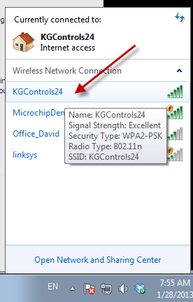
8 On Windows 7: a. Click on the network icon on the taskbar b. Find the IrrigationCaddyAP network, open it, and click on Connect. If IrrigationCaddyAP does not show right away, wait a few seconds until it shows up. You might have to repeat step 2.a to refresh the networks. c. Once you have connected, open a web browser and navigate to (You might have to wait up to 30 seconds before you are able to access the page after connecting to IrrigationCaddyAP. Refresh the page until it connects) 7

9 On MAC OS X: a. Click on the Wireless Signal indicator on the top bar. b. Find the IrrigationCaddyAP network, and select it. 8
 3.")
10 c. Once you have connected, open a web browser and navigate to (You might have to wait up to 30 seconds before you are able to access the page after connecting to IrrigationCaddyAP. Refresh the page until it connects) 3. Now you are connected to the IrrigationCaddy AdHoc network, however the objective should be to connect the IC to your own WiFi network, so that you can access the IC like any other networked device you might own. 4. On the menu bar click on Setup and then Settings 9

11 5. Open Network Settings, and click on the Scan Networks button. 10

12 6. When the scan finishes, it will display a list of available networks. Click on your preferred network to connect to it. 11

13 7. If the network is protected, you will be prompted to enter a passphrase. Enter the passphrase and click on Connect to Network. 8. The IC will then display a reconnection message, and it will reboot. When the IC reboots it will try to reconnect to the new network just selected. Now you need to connect your laptop/pc/portable device to reconnect to the new network so that you can access the IC in the new network. 12

14 9. To go back to the original network once again click on the network icon on the taskbar, and select your preferred network. On Windows 7: 13
15 14
16 On MAC OS X: Connecting Expansion Modules The IC-W1 zone capacity can be expanded to up to 43 zones by adding expansion modules (EXP-800). The expansion modules connect into the Expansion Port for the IC- W1. 15
17 Up to 4 expansion modules can be used by adding an expansion module hub (H-500). Reset to factory defaults To reset the unit to its factory default values press the right button and the left button at the same time, and keep them pressed for 4 seconds. The unit will then reset to factory defaults and restart. The display will say Resetting and Rebooting, at this point you can let the buttons go. 16

18 Chapter 2 Usage Going to the web address will present you with a Web Interface to the IC. The IC is capable of scheduling irrigation times using five different programs, which can be scheduled independently. The IC also provides the user with a Run Now program, which allows the user to execute a one time schedule, immediately after programming. Setting the Clock It is important that you set the IC s clock time to the current time. Steps: 1. Click on Settings. 2. Click on Clocks. Figure 2 Selection Column 17

19 Figure 3 Clock settings 3. Set the time: a. You can use the Sync Clocks button to synch the IC s clock with your computer s clock. b. You can also manually set it by clicking on the field next to the Set Datetime button. 18

20 Figure 4 Modifying the system time c. It is also possible to set the time using NTP (Network Time Protocol). Click on the Use NTP Time checkbox to enable the NTP time feature. NTP will try to connect to the NTP Server listed every few minutes, and update the local clock. A Timezone will also have to be specified. Figure 5 NTP Time Settings 19

21 4. Once the IC s clock has been set, this step does not have to be repeated. Setting a Program s Schedule Turn the program ON or OFF Turn the program ON by checking the ON/OFF radio buttons at the top. Figure 6 Turning programs on and off Selecting which days to run First select the program you would like to configure. Figure 7 Program Selection The IC supports several different programming schemes 20
 or odd numbered days (1, 3, 5 etc).")
22 INDIVIDUAL DAYS With this scheme you set what days of the week you would like to run your sprinklers. The program will then start only on the days you selected. Figure 8 Individual day selection EVEN / ODD DAYS With this scheme you select whether you would like the system to run on only even numbered days (2, 4, 6 etc) or odd numbered days (1, 3, 5 etc). Then you would select the individual week days you would like the system to run on. This way you can tell the system to run on even days, but not on weekends for example. Figure 9 Even / Odd Day Selection 1 If you would like to run even or odd days regardless of what day of the week it is then you would select every day of the week. 21

23 Figure 10 Even / Odd day selection 2 EVERY N DAYS With the Every N Days option you can tell the system to run exactly every specified number of days (i.e. every 3 days). As with the Even / Odd option, you can combine this option with the individual days, and also restrict which days of the week the system should run. For example you can tell the system to run every 2 days except for Mondays, and Wednesdays. Figure 11 Every N Days interval and day selection Every time the program is changed, and saved, the system will reset the time the program last run on, and start counting from the Sunday closest to 31 days prior to the current date. So if you make a change to a program that is set to run every 3 days, no matter what day it was last run, it will start counting from the Sunday closest to the date that falls 31 days prior to today. N O T E Info Odd option. The Even / Odd Days and Every N Days options cannot be combined. Once one is selected the other is disabled. If the Every N Days options has a number of days selected other than -, the Even / Odd option will not be available. Set the Every N Days number of days to - before selecting the Even / 22

24 Start Times The IC provides up to 5 start times per program. The start times are used to run the same program at different times during the day. For example, in certain scenarios it makes sense to water the same areas twice a day, once early in the morning and once later in the day. This can be accomplished by enabling one extra start from start times number 2, 3, 4 or 5. Start time 1 is always enabled, and it is the default start time. In other scenarios, where water runoff is a concern, the programs can be shortened, but more start times can be enabled thus maintaining the total amount of water output desired, while preventing runoff. To select the program s start time click on the text field below the Start Time heading, and a time picker will display. Then select the start time using the sliders. Figure 12 Program start time selection Setting zone run times To set the zone run times, under the Run Times heading, move the slider to the right to increase the amount of time a zone should run. The run time will display on top of the slider as well as to the right of the slider. A. Minimum time boundary Figure 13 Zone run time 23
25 B. Maximum time boundary. The zone cannot be set to run for more than the high time boundary. This limit can be changed from the settings page. C. The slider. D. The amount of time the zone will run. Using the Run Now Program The Run Now program allows you to run the system at the current moment. Just set the duration times on each one of the zones you are interested in running, and click on the Run Now button. This will start the system immediately. 24

26 Status Area The status area is divided in 5 sections. 1. The first section indicates whether the system is ON or OFF, and it allows the user to turn the system ON or OFF. Turning the system OFF means that the scheduler will not run and therefore the programs will never execute. However the device will continue to answer to network requests as usual. Figure 14 System ON OFF 2. The second section indicates the run time remaining for a program and for the zone currently running within that program. It also allows the user to stop the running zone. Figure 15 Time Remaining 3. The third section is a global status area for the zones. ON will display for a zone currently running, WAIT is for a zone that will run in the future after the zones above it have finished running, and OFF indicates the zone has already run, or the zone will not run at all. 25

27 Figure 16 Individual Zone Status 4. The fourth section indicates the rain sensor status. Figure 17 Rain Sensor Status 5. The fifth section indicates flow sensor status. Figure 18 Flow Sensor Status Turning the system OFF During the winter months you may not want to run the system. In that case, you can turn the system OFF by clicking on the OFF button in the System section. When you want 26

28 the programs to run again, you would simply click on the ON button. Note the system would still be powered on, but it will not turn on the sprinklers. Stopping Individual Zones While a program is running, you can stop individual zones by clicking on the Stop Zone button in the System section. If there is a zone waiting to run, that zone will then take over and start. If for some reason you would like to stop the program from continuing to run, you could click on the Stop Zone button for each one of the zones scheduled to run until there are no more zones ready to run. Calendar You can see a visual representation of when then programs will run by clicking on the Calendar link. Figure 19 Calendar link There are three possible calendar views, month, week, and day. By default month will display but you can change the view by clicking on the appropriate button on the top right hand corner of the view. Figure 20 Selecting calendar view The following is an example week view, where you can clearly see Program 1 will run on Monday starting at 6am, Program 2 will run on Wednesday starting at 10am, and Program 3 will start on Thursday at 8pm. 27

29 Figure 21 Calendar view Log If a USB Flash Drive has been inserted into the USB port, and you have a flow sensor connected, the unit will log its water usage to it. The data can then be displayed and plotted by clicking on the Log link. 28
30 Figure 22 Log Link The Log will display a calendar for the current month, and it will select the current day. The chart on the top will show the total water usage for each day. Clicking on the bar for the day, will change the chart on the bottom for the hours for each day, showing the water usage by hour. Figure 23 Log View 29

31 Chapter 3 Settings The settings page can be accessed by clicking on the Settings link. Figure 24 Settings Link Once you access the settings page the system settings are subdivided into sections. Figure 25 Settings sections 30
")
32 Firmware Version This section displays the firmware version the system is currently configured with. Figure 26 Firmware version Clocks It allows the user to set the system clock (see Setting the Clock under Usage) Figure 27 System Time 31

33 Network Settings The section displays the current network system settings and also allows for setting the hostname, DHCP or Static IP address configuration, IP Address (if static was chosen), port number, default gateway, and network mask. W A R N I N G Info Unless you are proficient with network terms, and understand how devices communicate in an Ethernet network, it is recommended that you don t change the default settings. Figure 28 Network settings Zone Blocks This section shows the connected expansion blocks if any. Each expansion block is identified by an ID, and an optional Name. Each block also indicates how many zones it 32

34 has, and whether the block is active or inactive. Once a block is connected to the main unit, the block registers itself with the unit, and the main unit will remember it. If the expander is then disconnected the block will show as INACTIVE in this section. The Nudge button allows the user to identify the expander if more than one expander is connected to the main unit. The ACT led on the expander will flash red rapidly when nudged. Figure 29 Zone Blocks Zone Names This section allows for the setting of the zone names. By default the zones are numbered and the names are empty. By giving a zone a descriptive name it is easier to remember which zone waters what area. Figure 30 Zone names 33

35 Authentication In here you can enable or disable authentication. By default authentication is disabled. By turning authentication ON, and setting a username and password, the next time you try to access the device you will be prompted for a username and password. If the credentials you enter don t match the credentials you specified here, you will not be allowed access to the IC s interface. If you forget the username and password, the only way to access the IC is to reset it to its factory default settings by (See Resetting to Factory Defaults) Figure 31 Authentication Other This section is reserved for other unrelated settings. Use Sensor 1 is intended to be used with a rain sensor. When a rain sensor is plugged into the rain sensor connector, you can use this setting to tell the system whether it should pay attention to the sensor or not. If the Use Sensor 1 setting is checked the system will check for a rain sensor, and if a sensor is present, it will water or stop watering according to the sensor state. If the sensor is wet, the system will not water. Use Flow Sensor should be selected when a flow sensor is available and can be connected to the IC. Units. If a flow sensor is in use, you can select the water usage is reported, in Liters or in Gallons. Units per Pulse. The IC supports pulse based flow sensors. This settings tells the IC how to translate each pulse into units. Does each pulse mean 1 Gallon? Or 2? etc Use #11 as Master Valve provides for the ability to dedicate a zone as a Master Valve. This means that if this setting is checked, every time a regular zone turns on, the #10 zone will also turn on. This zone can also be used to trigger a pump start relay. In systems where a water pump is used, a pump relay can be connected to zone #10 while this setting has been enabled. Every time a zone turns on due to the schedule, the pump relay would get triggered. The Max Zone Run Time setting is intended to globally limit the maximum amount of run time that a zone can be set at. The main purpose of the setting is to prevent programming mistakes and avoid unintended long periods of watering. 34

36 Figure 32 Other settings 35
37 Appendix A Firmware Upgrade To upgrade the firmware on the IC-W1 unit follow these steps: Steps: 1. Download the latest firmware from the IrrigationCaddy website at 2. Extract the contents of the ZIP file to a folder on your computer. 3. Copy the files into a USB Flash Key / Drive. 4. Insert the key into the USB slot in the caddy. 5. Pull the power cable from the unit to turn it OFF 6. Press the OK button while re inserting the power cable into the unit. 7. When you see the Info light next to the LCD blinking rapidly you can stop pressing the OK button. 8. Once the firmware is applied the unit will restart. Next you need to load the.bin file from the user interface. 9. Once the unit is up and running again, go to IC-W1 IP Address>/mpfsupload. 10. There select the.bin file that came with the firmware and click on the Upload button. After that the unit should be on the latest firmware. 36
38 Index Authentication, 34 Calendar, 27 clock, 17, 18, 20 common. See Connecting Valve Wires Connecting Valve Wires, 6 DHCP. See IP Drywall. See Mounting on the Wall Ethernet, 4, 32 even. See EVEN / ODD DAYS Even / Odd Days, 21 Every N Days, 22 indoor, 4, See Installation Steps Installation Steps, 4 IP DHCP, 32 Network, 32 Static, 32 master, 4, 6 Mounting on the Wall, 6 Network Settings, 32 odd. See EVEN / ODD DAYS rain sensor, 26, 34 reset, 16, 22, 34 Run Now, 17, 24 schedule, 4, 17 Settings, 30 Static IP. See IP Zone Names, 33 37

39 38
ETHERNET IRRIGATION CONTROLLER. Irrigation Caddy Model: ICEthS1. User Manual and Installation Instructions
 ETHERNET IRRIGATION CONTROLLER Irrigation Caddy Model: ICEthS1 User Manual and Installation Instructions I R R I G A T I O N C A D D Y M O D E L : I C E T H S 1 User Manual and Installation Instructions
3.5 EXTERNAL NETWORK HDD. User s Manual
 3.5 EXTERNAL NETWORK HDD User s Manual Table of Content Before You Use Key Features H/W Installation Illustration of Product LED Definition NETWORK HDD Assembly Setup the Network HDD Home Disk Utility
3.5 LAN HDD Enclosure User s Manual
 3.5 LAN HDD Enclosure User s Manual NOTE: 1. USB and LAN can t be used at the same time. 2. HDD should be formatted as FAT32. Please check Disk utility section in this manual. 3. For internet FTP usage,
FI8910W Quick Installation Guide. Indoor MJPEG Pan/Tilt Wireless IP Camera
 Model: FI8910W Quick Installation Guide (For Windows OS) (For MAC OS please go to page 17) Indoor MJPEG Pan/Tilt Wireless IP Camera Black White Package Contents IP Camera FI8910W with IR-Cut.x 1 DC Power
Manual. IP Sensor and Watchdog IPSW2210. I P S W 2 2 1 0 M a n u a l P a g e 1. Relay Output. Power input. 12VDC adapter LED Indicators. 2 Dry.
 IP Sensor and Watchdog IPSW2210 Manual Relay Output Power input 12VDC adapter LED Indicators 1 wire 2 Dry Output Green : Power Yellow: Link temperature & humidity contact inputs LED indicator sensor input
Quick Installation Guide
 V2.01 Model: FI9821W Quick Installation Guide Indoor HD Pan/Tilt Wireless IP Camera Black White For Windows OS ------- Page 1 For MAC OS ------- Page 16 ShenZhen Foscam Intelligent Technology Co., Ltd
N300 WiFi Range Extender WN2000RPT User Manual
 N300 WiFi Range Extender WN2000RPT User Manual December 2013 202-11333-01 350 East Plumeria Drive San Jose, CA 95134 USA Support Thank you for selecting NETGEAR products. After installing your device,
WRE6505. User s Guide. Quick Start Guide. Wireless AC750 Range Extender. Default Login Details. Version 1.00 Edition 1, 4 2014
 WRE6505 Wireless AC750 Range Extender Version 1.00 Edition 1, 4 2014 2.4G 5G Quick Start Guide User s Guide Default Login Details LAN IP Address 192.168.1.2 User Name admin www.zyxel.com Password 1234
Ethernet Radio Configuration Guide
 Ethernet Radio Configuration Guide for Gateway, Endpoint, and Repeater Radio Units April 20, 2015 Customer Service 1-866-294-5847 Baseline Inc. www.baselinesystems.com Phone 208-323-1634 FAX 208-323-1834
Installation. The product model shown in this QIG is TD-W8961ND, as an example.
 Installation The product model shown in this QIG is TD-W8961ND, as an example. Please use only wired network connections to configure the router. Power down all your network devices, including your computer(s)
Step by Step Guide for Upgrading Your NetCamPro Camera to Cloud Mode Using an Android Device
 Step by Step Guide for Upgrading Your NetCamPro Camera to Cloud Mode Using an Android Device Table of Contents Introduction...2 Backing Out Cloud Mode...2 Indoor Camera Factory Reset...2 Outdoor Camera
AC750 WiF Range Extender
 Model EX3700 User Manual May 2015 202-11487-01 350 East Plumeria Drive San Jose, CA 95134 USA Support Thank you for selecting NETGEAR products. After installing your device, locate the serial number on
Easy Setup Guide for the Sony Network Camera
 -878-191-11 (1) Easy Setup Guide for the Sony Network Camera For setup, a computer running the Microsoft Windows Operating System is required. For monitoring camera images, Microsoft Internet Explorer
mysensors mysensors Wireless Sensors and Ethernet Gateway Quick Start Guide Information to Users Inside the Box mysensors Ethernet Gateway Quick Start
 mysensors Information to Users mysensors Wireless Sensors and Ethernet Gateway Quick Start Guide This equipment has been tested and found to comply with the limits for a Class B digital devices, pursuant
Quick Start Guide. WRV210 Wireless-G VPN Router with RangeBooster. Cisco Small Business
 Quick Start Guide Cisco Small Business WRV210 Wireless-G VPN Router with RangeBooster Package Contents WRV210 Router Ethernet Cable Power Adapter Product CD-ROM Quick Start Guide Welcome Thank you for
Nighthawk AC1900 WiF Range Extender
 Nighthawk AC1900 WiF Range Extender Model EX7000 User Manual December 2014 202-11469-01 350 East Plumeria Drive San Jose, CA 95134 USA Nighthawk AC1900 WiF Range Extender Support Thank you for selecting
Click Main on the left hand side then click on Password at the top of the page.
 Q: How do I change the password on my router? A: Step 1. Log into the router by entering its IP address into a browser. The default IP address is http://192.168.1.1. The default username is admin with
Quick Start Guide. Cisco SPA232D Mobility Enhanced ATA
 Quick Start Guide Cisco SPA232D Mobility Enhanced ATA Package Contents Analog Telephone Adapter Ethernet Cable Phone Cable Power Adapter Quick Start Guide Product CD-ROM Welcome Thank you for choosing
A6210 WiFi USB Adapter 802.11ac USB 3.0 Dual Band User Manual
 802.11ac USB 3.0 Dual Band User Manual August 2014 202-11373-01 350 East Plumeria Drive San Jose, CA 95134 USA Support Thank you for selecting NETGEAR products. After installing your device, locate the
Home Wi-Fi Gateway Instructions
 Home Wi-Fi Gateway Instructions 1. Connect the gateway. Use the coaxial cable provided by BendBroadband to connect the cable port (A) to your cable outlet. 2. Connect your computer to the cable modem gateway
Chapter 1 Installing the Gateway
 Chapter 1 Installing the Gateway This chapter describes how to set up the wireless voice gateway on your Local Area Network (LAN), connect to the Internet, and perform basic configuration. For information
Quick Installation Guide
 V46.01 Model: FI8918W Quick Installation Guide Indoor Pan/Tilt Wireless IP Camera Black White For Windows OS ------- Page 1 For MAC OS ------- Page 11 ShenZhen Foscam Intelligent Technology Co., Ltd Quick
NETVIGATOR Wireless Modem Setup Guide. (TG789Pvn)
") NETVIGATOR Wireless Modem Setup Guide (TG789Pvn) Configure the NETVIGATOR Wireless Modem Make sure that system meets the following requirement prior to NETVIGATOR Wireless Modem usage: - Subscribers who
NETVIGATOR Wireless Modem Setup Guide (TG789Pvn) Configure the NETVIGATOR Wireless Modem Make sure that system meets the following requirement prior to NETVIGATOR Wireless Modem usage: - Subscribers who
1-Port Wireless USB 2.0 Print Server Model # APSUSB201W. Quick Installation Guide. Ver. 2A
 1-Port Wireless USB 2.0 Print Server Model # APSUSB201W Quick Installation Guide Ver. 2A Section 1 Step 1Connect one end of the Ethernet cable to the RJ-45 port of the Print Server and attach the other
Quick Installation Guide
 V48.01 Model: FI8919W Quick Installation Guide Outdoor Pan/Tilt Wireless IP Camera For Windows OS ------- Page 1 For MAC OS ------- Page 15 ShenZhen Foscam Intelligent Technology Co., Ltd Quick Installation
Link Link sys E3000 sys RE1000
 User Guide High Performance Extender Wireless-N Router Linksys Linksys RE1000 E3000Wireless-N Table of Contents Contents Chapter 1: Product Overview 1 Front 1 Top 1 Bottom 1 Back 2 Chapter 2: Advanced
N300 WiFi Range Extender
 Model EX2700 User Manual July 2014 202-11395-01 350 East Plumeria Drive San Jose, CA 95134 USA Support Thank you for selecting NETGEAR products. After installing your device, locate the serial number on
Networking Guide Redwood Manager 3.0 August 2013
 Networking Guide Redwood Manager 3.0 August 2013 Table of Contents 1 Introduction... 3 1.1 IP Addresses... 3 1.1.1 Static vs. DHCP... 3 1.2 Required Ports... 4 2 Adding the Redwood Engine to the Network...
Powerwifi USB Router in combination with the Powerwifi USB outdoor antenna
 INSTALLATION MANUAL Powerwifi USB Router in combination with the Powerwifi USB outdoor antenna INTRODUCTION The Powerwifi USB Router can be used together with the Powerwifi USB outdoor antenna. This creates
How To Use 1Bay 1Bay From Awn.Net On A Pc Or Mac Or Ipad (For Pc Or Ipa) With A Network Box (For Mac) With An Ipad Or Ipod (For Ipad) With The
 With A Network Box (For Mac) With An Ipad Or Ipod (For Ipad) With The") 1-bay NAS User Guide INDEX Index... 1 Log in... 2 Basic - Quick Setup... 3 Wizard... 3 Add User... 6 Add Group... 7 Add Share... 9 Control Panel... 11 Control Panel - User and groups... 12 Group Management...
1-bay NAS User Guide INDEX Index... 1 Log in... 2 Basic - Quick Setup... 3 Wizard... 3 Add User... 6 Add Group... 7 Add Share... 9 Control Panel... 11 Control Panel - User and groups... 12 Group Management...
AC1200 WiFi Range Extender
 Model EX6200 User Manual February 2014 202-11298-01 350 East Plumeria Drive San Jose, CA 95134 USA Support Thank you for selecting NETGEAR products. After installing your device, locate the serial number
Quick Installation Guide DAP-1360. Wireless N 300 Access Point & Router
 DAP-1360 Wireless N 300 Access Point & Router BEFORE YOU BEGIN Delivery Package Access point DAP-1360 Power adapter DC 12V Ethernet cable (CAT 5E) (brochure). If any of the items are missing, please contact
Powerline 500 WiFi Access Point (XWN5001) Installation Guide
 Installation Guide") Powerline 500 WiFi Access Point (XWN5001) Installation Guide Support Thank you for selecting NETGEAR products. After installing your device, locate the serial number on the label of your product and use
Powerline 500 WiFi Access Point (XWN5001) Installation Guide Support Thank you for selecting NETGEAR products. After installing your device, locate the serial number on the label of your product and use
Experience Next-Generation WiFi
 Do More Experience Next-Generation WiFi Your new WiFi extender supports the 802.11ac networking standard. This new standard offers better speed, improved reliability, and more range than older WiFi networking
Networking. General networking. Networking overview. Common home network configurations. Wired network example. Wireless network examples
 Networking General networking Networking overview A network is a collection of devices such as computers, printers, Ethernet hubs, wireless access points, and routers connected together for communication
FreeAgent DockStar Network Adapter User Guide
 FreeAgent DockStar Network Adapter User Guide FreeAgent DockStar Network Adapter User Guide 2010 Seagate Technology LLC. All rights reserved. Seagate, Seagate Technology, the Wave logo, and FreeAgent are
genie app and genie mobile app
 genie app and genie mobile app User Manual 350 East Plumeria Drive San Jose, CA 95134 USA June 2012 202-10933-02 v1.0 2012 NETGEAR, Inc. All rights reserved No part of this publication may be reproduced,
Quick Start Guide. DVR DS-7200HWI-SH Series DVR. www.hikvision.com. First Choice For Security Professionals
 Quick Start Guide DVR DS-7300HWI-SH Series DVR DS-7200HWI-SH Series DVR NOTE: For more detailed information, refer to the User s Manual on the CD-ROM. You must use your PC or MAC to access the files. www.hikvision.com
Honeywell Internet Connection Module
 Honeywell Internet Connection Module Setup Guide Version 1.0 - Page 1 of 18 - ICM Setup Guide Technical Support Setup - Guide Table of Contents Introduction... 3 Network Setup and Configuration... 4 Setting
Quick Start Guide NVR DS-7104NI-SL/W NVR. www.hikvision.com. First Choice For Security Professionals
 Quick Start Guide NVR DS-7104NI-SL/W NVR NOTE: For more detailed information, refer to the User s Manual on the CD-ROM. You must use your PC or MAC to access the files. www.hikvision.com Quick Start 1.
Powerline 500 WiFi Access Point (XWNB5201) Installation Guide
 Installation Guide") Powerline 500 WiFi Access Point (XWNB5201) Installation Guide Support Thank you for selecting NETGEAR products. After installing your device, locate the serial number on the label of your product and use
Powerline 500 WiFi Access Point (XWNB5201) Installation Guide Support Thank you for selecting NETGEAR products. After installing your device, locate the serial number on the label of your product and use
This section will focus on basic operation of the interface including pan/tilt, video, audio, etc.
 Catalogue Basic Operation... 2 For Internet Explorer... 2 For Other Non-IE Web Browsers... 5 Camera Settings... 6 System... 6 About... 6 PT Setting... 7 Backup and Restore Setup... 8 NTP Setting... 8 System
WAP3205 v2. User s Guide. Quick Start Guide. Wireless N300 Access Point. Default Login Details. Version 1.00 Edition 2, 10/2015
 WAP3205 v2 Wireless N300 Access Point Version 1.00 Edition 2, 10/2015 Quick Start Guide User s Guide Default Login Details Web Address http://zyxelsetup Password www.zyxel.com 1234 Copyright 2014 ZyXEL
Assign a static IP address (192.168.1.100) for your computer. Please refer to T3 in Troubleshooting guide on page 10 if you need assistance.
 for your computer. Please refer to T3 in Troubleshooting guide on page 10 if you need assistance.") Assign a static IP address (192.168.1.100) for your computer. Please refer to T3 in Troubleshooting guide on page 10 if you need assistance. You may need to write down the original settings as a backup.
Assign a static IP address (192.168.1.100) for your computer. Please refer to T3 in Troubleshooting guide on page 10 if you need assistance. You may need to write down the original settings as a backup.
FOR MORE INFORMATION. 125 8880 or from a non-telstra phone 13 2200 and say pre-paid telstra.com/ppmbb visit a telstra store or partner
 FOR MORE INFORMATION 125 8880 or from a non-telstra phone 13 2200 and say pre-paid telstra.com/ppmbb visit a telstra store or partner getting to know your telstra pre-paid 4G WI-FI (760S) LET S GET THIS
PePWave Surf Series PePWave Surf Indoor Series: Surf 200, AP 200, AP 400
 PePWave Surf Series PePWave Surf Indoor Series: Surf 200, AP 200, AP 400 PePWave Surf Outdoor Series: Surf AP 200/400-X, PolePoint 400-X, Surf 400-DX User Manual Document Rev. 1.2 July 07 COPYRIGHT & TRADEMARKS
DNS-312H Network Attached Storage
 This product can be set up using any current web browser, i.e., Internet Explorer 5x, and Netscape Navigator 4x or above. DNS-312H Network Attached Storage Before You Begin 1. If you purchased this storage
EM6230 e-camview HD outdoor IP camera
 EM6230 e-camview HD outdoor IP camera 2 ENGLISH EM6230 e-camview HD outdoor IP camera Table of contents 1.0 Introduction... 3 1.1 Packing contents... 3 1.2 Requirements to access the camera.... 3 1.3 Major
Apple AirPort Extreme (ME918ZP/A) Router Guide (MAC OS version)
 Router Guide (MAC OS version)") Apple AirPort Extreme (ME918ZP/A) Router Guide (MAC OS version) 0 1 Get to know the Apple AirPort Extreme Router... 2 2 Connecting Apple AirPort... 3 A. Setting up Internal Wi-Fi network with the Apple
Apple AirPort Extreme (ME918ZP/A) Router Guide (MAC OS version) 0 1 Get to know the Apple AirPort Extreme Router... 2 2 Connecting Apple AirPort... 3 A. Setting up Internal Wi-Fi network with the Apple
Installation. Note The product model shown in this QIG is TD-W8951ND, as an example.
 Installation The product model shown in this QIG is TD-W8951ND, as an example. Please use only wired network connections to configure the router. Power down all your network devices, including your computer(s)
Energy Communication Unit (ECU)
") Altenergy Power System Energy Communication Unit (ECU) Installation and User Manual (For ECU-3 V3.8) ALTENERGY POWER SYSTEM INC. All rights reserved TABLE OF CONTENTS 1.0 Introduction... 2 2.0 Installation...
Altenergy Power System Energy Communication Unit (ECU) Installation and User Manual (For ECU-3 V3.8) ALTENERGY POWER SYSTEM INC. All rights reserved TABLE OF CONTENTS 1.0 Introduction... 2 2.0 Installation...
Fibe Internet Connection Hub Reference Guide
 Fibe Internet Connection Hub Reference Guide FibeInternet_ConnectionHub_ReferenceGuide_Eng_V7 1 Bell Internet Service Agreement Use of the Bell Internet service is subject to the terms and conditions of
Home Station ADSL. You may also use the following address (regardless of whether you have changed the primary address or not):
:") TABLE OF CONTENTS 1 Introduction 1 2 User interface overview 2 3 LAN and WLAN settings 8 4 Setting the Internet connection 11 5 Settings and status of devices connected to your router 13 6 Configure applications
TABLE OF CONTENTS 1 Introduction 1 2 User interface overview 2 3 LAN and WLAN settings 8 4 Setting the Internet connection 11 5 Settings and status of devices connected to your router 13 6 Configure applications
mysensors mysensors Wireless Sensors and and Cellular Gateway Quick Start Guide Information to Users Inside the Box
 mysensors mysensors Wireless Sensors and and Cellular Gateway Quick Start Guide Information to Users The mysensors wireless products referenced in this Quick Start Guide have been tested to comply with
1. Do I need to upgrade my Broadband at Home modem firmware?
 1. Do I need to upgrade my Broadband at Home modem firmware? Please follow the steps below to ensure you have the most up to date firmware for your Broadband at Home modem. 1. Make sure that you have connected
B890 4G LTE Smart Hub Getting Started Guide
 B890 4G LTE Smart Hub Getting Started Guide HUAWEI TECHNOLOGIES CO., LTD. Thank You for Purchasing the B890 4G LTE Smart Hub! Before You Begin What s in the Box : 1. B890 4G LTE Smart Hub 2. Power adapter
MN-700 Base Station Configuration Guide
 MN-700 Base Station Configuration Guide Contents pen the Base Station Management Tool...3 Log ff the Base Station Management Tool...3 Navigate the Base Station Management Tool...4 Current Base Station
3.5 Mobile LAN Disk. User Guide
 3.5 Mobile LAN Disk User Guide Contents 1. Hardware...2 1.1 Power...2 1.2 Ports...2 1.3 Reset Button...2 1.4 LEDs...2 1.5 Front View...3 1.6 Rear View...3 2. Installation....... 4 2.1 Requirements 4 2.2
Configuring the wireless security of your Linksys Wireless-N router through the web-based setup page
 Contents Configuring the wireless security of your Linksys Wireless-N router through the web-based setup page.. 2 Checking the Linksys router s wireless settings through the web-based setup page and adding
SATO Network Interface Card Configuration Instructions
 SATO Network Interface Card Configuration Instructions Table of Contents 1. Reset of wired/wireless interface card... 3 2. Installing the All-In-One Utility (recommended)... 4 3. Configuring wired/wireless
Sky Broadband upgrading your router software
 Sky Broadband upgrading your router software Why upgrade to the new software? As with all aspects of the services we provide, we have been working to enhance the performance of the software in your wireless
USING THE MODEL V800 VELOCITY CLOCK
 USING THE MODEL V800 VELOCITY CLOCK Velocity Clocks are advanced clocks with many options and features. They can be used to restrict employee punching, allowing employees to punch at the clock during their
Smart Card Authentication. Administrator's Guide
 Smart Card Authentication Administrator's Guide October 2012 www.lexmark.com Contents 2 Contents Overview...4 Configuring the applications...5 Configuring printer settings for use with the applications...5
Router Setup Manual. NETGEAR, Inc. 4500 Great America Parkway Santa Clara, CA 95054 USA 208-10060-01 2006-03-17
 NETGEAR, Inc. 4500 Great America Parkway Santa Clara, CA 95054 USA 208-10060-01 2006-03-17 2006 by NETGEAR, Inc. All rights reserved. Trademarks NETGEAR is a trademark of Netgear, Inc. Microsoft, Windows,
Sensatronics Senturion Environmental Monitor Operations Manual
 Sensatronics Senturion Environmental Monitor Operations Manual Farrall Hall Annex installation Developed by: Zach Andrews Eric Barr Brandon White 1 Opening disclaimer: This is not the official manual of
Ithaca itherm, POSjet & BANKjet Printers Ethernet Adapters Setup Guide
 Ithaca itherm, POSjet & BANKjet Printers Ethernet Adapters 100-05203 Rev A 4/26/04 Contents Contents... 2 Ethernet Connection... 3 Configuration... 4 Locator Program... 4 Installation... 4 Using Locator...
Savvius Insight Initial Configuration
 The configuration utility on Savvius Insight lets you configure device, network, and time settings. Additionally, if you are forwarding your data from Savvius Insight to a Splunk server, You can configure
BEGINNER S SETUP GUIDE for NANOSTATION 2 and other Ubiquity devices using AirOS firmware
 BEGINNER S SETUP GUIDE for NANOSTATION 2 and other Ubiquity devices using AirOS firmware Windows XP Make sure the Nanostation 2 (Nano for short) is connected to your computer s network card with network
Connecting the DG-102S VoIP Gateway to your network
 Contents of Package: DG-102S VoIP Station Gateway Power adapter CD-ROM, including User s Manual Quick Install Guide Requirements: RS-232 Console Cable Two RJ-45 CAT-5 Straight-Through Cables For more information
Chapter 3 Management. Remote Management
 Chapter 3 Management This chapter describes how to use the management features of your ProSafe 802.11a/g Dual Band Wireless Access Point WAG102. To access these features, connect to the WAG102 as described
Quick Start Guide. Hybrid DVR DS-9000 Series Hybrid DVR DS-7600 Series Hybrid DVR. NVR DS-9600 Series NVR
 Quick Start Guide Hybrid DVR DS-9000 Series Hybrid DVR DS-7600 Series Hybrid DVR NVR DS-9600 Series NVR Analog DVR DS-9100 Series DS-8100 Series DS-7300 Series DS-7200 Series NOTE: For more detailed information,
Quick Setup Guide High Power Wireless Ethernet Converter WLI-TX4-G54HP
 Quick Setup Guide High Power Wireless Ethernet Converter WLI-TX4-G54HP This guide is intended to help you quickly and easily install your High Power Wireless Ethernet Converter. For more setup and configuration
RouteFinder SOHO. Quick Start Guide. SOHO Security Appliance. EDGE Models RF825-E, RF825-E-AP CDMA Models RF825-C-Nx, RF825-C-Nx-AP
 RouteFinder SOHO SOHO Security Appliance EDGE Models RF825-E, RF825-E-AP CDMA Models RF825-C-Nx, RF825-C-Nx-AP Quick Start Guide RouteFinder RF825 Series Quick Start Guide RouteFinder SOHO Security Appliance
Epson Stylus CX9475Fax. Start Here
 Epson Stylus CX9475Fax Start Here Unpack Caution: Do not open ink cartridge packages until you are ready to install the ink. Cartridges are vacuum packed to maintain reliability. If anything is missing,
Turn on all of your network devices and then check to see if the LEDs on the Access Point display normally as the diagram below describes.
 Connect to the Access Point with the Ethernet cable or via wireless. The default SSID of the Access Point is TP-LINK_ XXXXXX. The XXXXXX is the last 6 characters of the Access Point s MAC address. Plug
Deployment Guide: Transparent Mode
 Deployment Guide: Transparent Mode March 15, 2007 Deployment and Task Overview Description Follow the tasks in this guide to deploy the appliance as a transparent-firewall device on your network. This
Quick Installation Guide
 Quick Installation Guide (For Windows & Mac OS) Outdoor Wireless IP Camera Package Contents V1.1 IP Camera Power Adapter Resource CD Ethernet Cable Mounting Bracket(except FI8919) Wi-Fi Antenna Quick Installation
N300 WiFi Range Extender
 Model WN3000RP User Manual September 2014 202-11409-01 350 East Plumeria Drive San Jose, CA 95134 USA Support Thank you for selecting NETGEAR products. After installing your device, locate the serial number
ipdatatel Wi-Fi BAT Installation and Configuration Guide
 ipdatatel Wi-Fi BAT Installation and Configuration Guide This guide is for customers who want install the ipdatatel equipment before their programming appointment. This guide covers installing the IPD-Wifi-BAT
TL-PS310U Single USB 2.0 Port MFP and Storage Server
 TL-PS310U Single USB 2.0 Port MFP and Storage Server Rev: 2.0.0 1910010313 Contents Chapter 1 Introduction... 1 1.1 Product Overview...1 1.2 Network Management...1 1.3 Components and Features...1 1.4 Hardware
N750 WiFi DSL Modem Router Premium Edition
 Support Thank you for purchasing this NETGEAR product. After installing your device, locate the serial number on the label of your product and use it to register your product at https://my.netgear.com.
Chapter 1 Connecting the Router to the Internet
 Chapter 1 Connecting the Router to the Internet This chapter describes how to set up the router on your Local Area Network (LAN) and connect to the Internet. It describes how to set up your wireless ADSL
Ethernet Interface Manual Thermal / Label Printer. Rev. 1.01 Metapace T-1. Metapace T-2 Metapace L-1 Metapace L-2
 Ethernet Interface Manual Thermal / Label Printer Rev. 1.01 Metapace T-1 Metapace T-2 Metapace L-1 Metapace L-2 Table of contents 1. Interface setting Guiding...3 2. Manual Information...4 3. Interface
Installation Guide Wireless 4-Port USB Sharing Station. GUWIP204 Part No. M1172-a
 Installation Guide Wireless 4-Port USB Sharing Station 1 GUWIP204 Part No. M1172-a 2011 IOGEAR. All Rights Reserved. PKG-M1172-a IOGEAR, the IOGEAR logo, MiniView, VSE are trademarks or registered trademarks
Installation. If you currently use a modem, disconnect it now - the Modem Router will replace your current modem.
 Installation Note Please use only wired network connections to configure the Modem Router. If you currently use a modem, disconnect it now - the Modem Router will replace your current modem. Connect your
If no telephone is needed, please connect the LINE port of the Modem Router to the wall jack using the telephone line directly.
 Note Please use only wired network connections to configure the Router. Power down all of your network devices, including your computer(s) and the Modem Router. If you currently use a modem, disconnect
Preparing the Computers for TCP/IP Networking
 Configuration Preparing the Computers for TCP/IP Networking Configuring Windows 98, and ME for TCP/IP Networking Verifying TCP/IP Properties Configuring Windows 2000 or XP for IP Networking Install or
Windows 10.1 Tablet (UB-15MS10 and UB-15MS10SA) FAQ December 2014
 FAQ December 2014") Windows 10.1 Tablet (UB-15MS10 and UB-15MS10SA) FAQ December 2014 Navigation... 2 Question 1: What are charms used for?... 2 Question 2: How do I navigate while using a mouse or trackpad?... 3 Question
Windows 10.1 Tablet (UB-15MS10 and UB-15MS10SA) FAQ December 2014 Navigation... 2 Question 1: What are charms used for?... 2 Question 2: How do I navigate while using a mouse or trackpad?... 3 Question
MobileLite Wireless G2 5-in-1 Mobile Companion User Manual
 MobileLite Wireless G2 5-in-1 Mobile Companion User Manual Document No. 480-MLWG2-021315.A00 Kingston MobileLite Wireless Page 1 of 21 Table of Contents Introduction... 3 What s Included:... 3 Getting
Support Package Contents AC1600 WiFi VDSL/ADSL Ethernet cable Trademarks Modem Router Compliance Phone cable Modem router
 Support Thank you for purchasing this NETGEAR product. After installing your device, locate the serial number on the label of your product and use it to register your product at https://my.netgear.com.
Check Your Package Contents. CD-ROM containing Manual and Warranty
 This product can be set up using any current web browser, i.e., Internet Explorer 6 or Netscape Navigator 6.2.3. DVA-G3340S Wireless VoIP Router Before You Begin If you purchased this Router to share your
PART 1 CONFIGURATION 1.1 Installing Dashboard Software Dashboardxxx.exe Administration Rights Prerequisite Wizard
 Omega Dashboard 1 PART 1 CONFIGURATION 1.1 Installing Dashboard Software Find the Dashboardxxx.exe in the accompanying CD or on the web. Double click that to install it. The setup process is typical to
Online Monitoring User Guide
 High Resolution Temperature Sensing Strip Online Monitoring User Guide 888.637.3282 www.nerdata.com Page 1 of 26 Contents The Aurora Online Monitoring System... 3 1. Creating an Account on the Aurora Online
Frequently Asked Questions
 FAQs Frequently Asked Questions Connecting your Linksys router to the Internet 1 What computer operating systems does my Linksys router support? 1 Why can t I connect my computer or device to my router?
Wireless-N Range Extender. User Manual
 Wireless-N Range Extender User Manual Version A1.0, June 19, 2012 Preface This manual provides information related to the installation and operation of this Wireless-N Range Extender. The individual reading
QUICK START GUIDE CX-MC200LE-VZ
 QUICK START GUIDE CX-MC200LE-VZ LTE/EV-DO Business-Grade Modem For use with Juniper Networks CX111 3G/4G Bridge with Enhanced Performance and Reliability GETTING READY TO USE YOUR CX-MC200LE-VZ MODEM Thank
WIRELESS INTERNET TROUBLESHOOTING GUIDE. 320.834.5151 888.236.3574 www.gctel.com. Help Desk 320.834.5155
 WIRELESS INTERNET TROUBLESHOOTING GUIDE 320.834.5151 888.236.3574 www.gctel.com Help Desk 320.834.5155 Table of Contents Check Physical Connection Connection Diagram - Page 1 Power Inserter - Page 2 Identify
10/2011 - English Edition 1. Quick Start Guide. NWA1100N-CE CloudEnabled Business N Wireless Access Point
 10/2011 - English Edition 1 Quick Start Guide NWA1100N-CE CloudEnabled Business N Wireless Access Point Package Contents - 1 x ZyXEL NWA1100N-CE Access Point - 2 x Detachable Antennas - 1 x Power Adapter
Energy Communication Unit (ECU)
") Altenergy Power System Energy Communication Unit (ECU) Installation and User Manual (For ECU-3 V3.7) Version:3.0 ALTENERGY POWER SYSTEM INC. All rights reserved TABLE OF CONTENTS 1.0 Introduction... 2
Altenergy Power System Energy Communication Unit (ECU) Installation and User Manual (For ECU-3 V3.7) Version:3.0 ALTENERGY POWER SYSTEM INC. All rights reserved TABLE OF CONTENTS 1.0 Introduction... 2
DATA PROJECTOR XJ-A147/XJ-A247/XJ-A257 XJ-M146/XJ-M156 XJ-M246/XJ-M256. XJ-A Series. XJ-M Series. Network Function Guide
 DATA PROJECTOR EN XJ-A Series XJ-A147/XJ-A247/XJ-A257 XJ-M Series XJ-M146/XJ-M156 XJ-M246/XJ-M256 Network Function Guide In this manual, XJ-A Series and XJ-M Series refer only to the specific models listed