User Guide for 3 axis TB6560 driver board
|
|
|
- Ashlynn King
- 9 years ago
- Views:
Transcription
1 User Guide for 3 axis TB6560 driver board Product Features: Toshiba TB6560AHQ chip - High power, maximum 3A drive current chipset! 1-1/16 microstep setting - Higher accuracy and smoother operation than standard 1, 1/2 step! Adjustable drive current settings for each axis - 25%,50%,75%,100% of full current can be set for different stepper motors Overload, over-current and over-temperature safety - Full protection for your computer and peripheral equipment! On board current switching - Power output can be set according to specific user requirement! Full closed-type optical isolation to protect the user's computer and equipment Relay spindle interface - Outputs Max. 36V 7.5A for spindle motors or coolant pump (only one device can be powered by this output!) 4 channel inputs interface- Can be used for XYZ limit and emergency stop! Professional design - Two stage signal processing with super anti-jamming! Bipolar constant current chopper drive with non-resonant region - Controls motors smoothly through range without creep effect! Four control inputs (divided into pairs of knives) - Allows setting of limit and emergency stop! Universal architecture - Supports most parallel software MACH3,KCAM4,EMC2 etc! Dip settings: ON 0 OFF Current Setting TQ1 TQ2 Decay Mode Settings DCY2 DCY1 MicroStep Settings M2 M1 100% ON ON Normal 0% FAST ON ON 1 ON ON 75% OFF ON 25% ON OFF 1/2 ON OFF 50% ON OFF 50% OFF ON 1/8 OFF OFF 20% OFF OFF 100% SLOW OFF OFF 1/16 OFF ON

2 Important Notes: Power supply DC 12-34V (not included) *Voltage Selection: 12-16V DC power supply for Nema 17 stepper motors 16-24V DC power supply for Nema 23 stepper motors 24-36V DC power supply for Nema 34 stepper motors (High voltage will burn up the chips or stepper motors!!!) *Ampertage Selection: Output current of the power supply can be calculated by the following expressions: Output current = Rated current of your stepper motors * quantity + 2A (For example, if you want to drive 3 * 3A Nema 23 stepper motors, theoretically 24V 11A DC power supply is recommended, but higher power such as 24V 15A also will be good. If you are not sure about the selection of power supply, please feel free to contact us for help) The power output of 12V shall be applied to the radiator fan of 12V Driver output compatible with 2 or 4 phase, 4,6 or 8 lead stepper motors, 3A max. Suitable for unipolar or bipolar stepper motors. Voltage regulated spindle speed controlled by parallel interface as function of supply voltage.

3 The definition of 1-PIN 25 (25) of Parallel Interface: Pin1 Pin2 Pin3 Pin4 Pin5 Pin6 Pin7 Pin8 Pin9 Pin10 Pin11 Pin12 X Step Y Enable Y Dir Z Dir Z Step Z Enable X Dir Y Step spindle X Home Y Home Z Home 1 Enabl 1 Enabl 1 CW motor 0 - Disabl 0 - Disabl 0 - CCW 1 - ON Pin13 Pin14 Pin15 Pin16 Pin17 Pin18 to Pin25 EStop X Enable Expand Expand Expand GND GND GND 1 Enabl input1 output 1 output2 0 - Disabl The definition of 1-PIN15 (15) of Manual Interface: Pin1 Pin2 Pin3 Pin4 Pin5 Pin6 Pin7 Pin8 Pin9 Pin10 Pin11 Pin12 Pin13 Pin14 Pin15 X Step X Spindle X Dir Y Z Dir Z Step Z VDD GND EStop Y Step Y Dir Z Home Y Home Enable Motor Enable Enable +5V P13(25) P12(25) P11(25) The definition of 4 channel inputs interface: Pin1 Pin2 Pin3 Pin4 Pin5 GND EStop Z Home Y Home X Home Pin13(25) Pin12(25) Pin11(25) Pin10(25) Pin11(15) Pin14(15) Pin15(15)

4 Limit setting for reference: The definition of output Interface: Pin1 Pin2 Pin3 Pin4 Pin5 Pin6 Pin7 Pin8 Pin9 Pin10 Pin11 Pin12 Pin13 Pin14 Pin15 Pin16 Pin17 VDD GND XA+ XA- XB+ XB- YA+ YA- YB+ YB- ZA+ ZA- ZB+ ZB- MO/ V+ GND MO -

5 Instructions of MACH3 Fig.1 Open MACH3 software, select mach3mill, and then click OK. Please refer to Fig.1
6 Fig.2 The interface of MACH3 is displayed as Fig.2. The frequently-used action buttons are listed on the interface. We can configure MACH software at first.
7 Fig.3 Click PORT & PIN sub-menu of config menu. Please refer to Fig.3. Please refer to Fig.4


8 Fig.4 To set up the basic frequency within the above Circle 1. This parameter will affect the rotational speed of the motor. After the setup of basic frequency, select Circle 2 where Configuration Scripting will be defined, please refer to Fig.5. Fig.5

9 To modify the software settings according to the definition of Parallel Interface which is detailed in the above circle. Fig.6 Then select the output signals column, as shown in Fig.6, and set up the corresponding items per the setup described in the circle.

10 Fig.7 After all have been set up, open the G CODE that needs to run, as shown in Fig.7
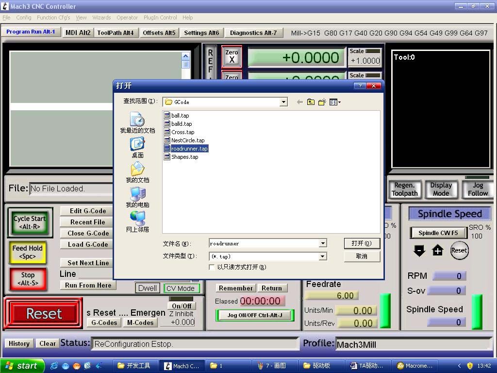
11 Fig.8
12 Fig.9 After G CODE has been opened, you may see the red button RESET flashing. Click RESET to stop the flashing and then press CYCLESTART at the location of Circle 2 *Simple solutions if the driver does not work properly: Please double check the software settings according to the Fig.5 and Fig.6 Please conform the parallel cable has been pluged tightly Please turn off the power supply before changing dip settings Please use stable high quality DC power supply for this driver Problems in Mach3 using, Please refer to the Mach 3 User Manual If problem persist, please feel free to contact us!
Four/Five Axis TB6560 CNC Driver Users Manual
 Four/Five Axis TB6560 CNC Driver Users Manual Revision 2.0. Oct. 16. 2009 1 Content 1. GENERAL INFORMATION... 3 1.1. Scope... 3 1.2. General Description... 3 1.3. Key Features... 3 2. Descriptions of 4/5-AXIS
Three Axis TB6560 CNC Driver Users Manual
 Three Axis TB6560 CNC Driver Users Manual Revision 2.0 Oct. 16. 2009 1 Content 1. GENERAL INFORMATION... 3 1.1. Scope... 3 1.2. General Description... 3 2. Descriptions of 3-AXIS CNC Board... 3 2.1. Photo
MANUAL FOR BREAKOUT BOARD HG06
 MANUAL FOR BREAKOUT BOARD HG06 INFORMATION IS SPECIFIC TO OUR PRODUCTS AND CAN CAUSE DAMAGE IF USED WITH NONE COMPATIBLE PRODUCTS SO PLEASE CHECK WITH YOUR SUPPLIER FOR COMPATIBILITY These drawings are
mach3 cnc Stepper Motor Controller operation instruction ST6560-T3 3axis mach3 cnc
 ST6560-T3 3axis mach3 cnc Stepper Motor Controller operation instruction 1 Content ST6560-T3 3axis...1 I. features of ST6560-T3...3 Ⅱ Applications:...3 Ⅲ Electrical drawing...4 V. Definition on pins of
SYSTEM 45. C R H Electronics Design
 SYSTEM 45 C R H Electronics Design SYSTEM 45 All in one modular 4 axis CNC drive board By C R Harding Specifications Main PCB & Input PCB Available with up to 4 Axis X, Y, Z, & A outputs. Independent 25
SYSTEM 4C. C R H Electronics Design
 SYSTEM 4C C R H Electronics Design SYSTEM 4C All in one modular 4 axis CNC drive board By C R Harding Specifications Main PCB & Input PCB Available with up to 4 Axis X, Y, Z, A outputs. Independent 25
Mach3 Tutorial Setting up a basic three axis milling machine. Based on Mach3 2.0
 Mach3 Tutorial Setting up a basic three axis milling machine. Based on Mach3 2.0 Purpose. The purpose of this tutorial is to help and to guide the user to, step by step, set up and tune the Mach3 CNC controller
XS-3525/8S-3. Preliminary DataSheet Version 2.02
 XS-3525/8S-3 Preliminary DataSheet Version 2.02 X The XS-3525/8S-3 microstepping stepper motor driver is the perfect choice for CNC retrofitting of desktop and small benchtop milling machines. Connect
Mach3 Sample Configuration with 3 Axis and PWM Spindle Speed Using a Single Parallel Port
 1.0 Preface This document is NOT a complete Mach3 tutorial. Users of this document should be familiar with how to run the Mach3 operation and configuration interfaces. We recommend that you review the
Data Sheet. Adaptive Design ltd. Arduino Dual L6470 Stepper Motor Shield V1.0. 20 th November 2012. L6470 Stepper Motor Shield
 Arduino Dual L6470 Stepper Motor Shield Data Sheet Adaptive Design ltd V1.0 20 th November 2012 Adaptive Design ltd. Page 1 General Description The Arduino stepper motor shield is based on L6470 microstepping
Mini Breakout-Board. CNC Interface for LPT Port. Installation Manual Version 4
 Mini CNC Interface for LPT Port Version 4 Product Brief This breakout-board is designed to connect up to four stepper or servo drives to the parallel port of a PC. This requires the use of a CNC controller
Table of Contents Getting Started... 3 The Motors... 4 The Control Board... 5 Setting up the Computer with Mach3... 6 Starting up the Equipment...
 User Manual Table of Contents Getting Started... 3 The Motors... 4 The Control Board... 5 Setting up the Computer with Mach3... 6 Starting up the Equipment... 12 G-Code Example... 13 2 Getting Started
CNC Milling Engraving machine G4030A Instruction manual
 CNC Milling Engraving machine G4030A Instruction manual 1. Safety notes Every machine controlled by computer (PC) can be really dangerous for human life and health. Comply with bolow rules and use Your
DMX-K-DRV. Integrated Step Motor Driver + (Basic Controller) Manual
 Manual") DMX-K-DRV Integrated Step Motor Driver + (Basic Controller) Manual DMX-K-DRV Manual page 1 rev 1.33 COPYRIGHT 2007 ARCUS, ALL RIGHTS RESERVED First edition, June 2007 ARCUS TECHNOLOGY copyrights this document.
DMX-K-DRV Integrated Step Motor Driver + (Basic Controller) Manual DMX-K-DRV Manual page 1 rev 1.33 COPYRIGHT 2007 ARCUS, ALL RIGHTS RESERVED First edition, June 2007 ARCUS TECHNOLOGY copyrights this document.
UIM2901-5A MACH3 breakout board
 User Manual UIM2901-5A MACH3 Breakout Board UIM2901-5A MACH3 Breakout Board UIM2901-5A MACH3 breakout board Features General DB25 interface between PC and user device Fully buffered opto-isolated I/O (Input
PWM Spindle Speed with Mach3, SmoothStepper, PMDX-126 and PMDX-106 or PDMX-107
 1.0 Overview This application note describes one method of configuring Mach3 and the SmoothStepper Plug-In in order to generate the necessary PWM spindle control signals when using a PMDX-126 and either
Micro-Step Driving for Stepper Motors: A Case Study
 Micro-Step Driving for Stepper Motors: A Case Study N. Sedaghati-Mokhtari Graduate Student, School of ECE, University of Tehran, Tehran, Iran n.sedaghati @ece.ut.ac.ir Abstract: In this paper, a case study
Digital I/O: OUTPUT: Basic, Count, Count+, Smart+
 Digital I/O: OUTPUT: Basic, Count, Count+, Smart+ The digital I/O option port in the 4-Series provides us with 4 optically isolated inputs and 4 optically isolated outputs. All power is supplied externally.
CNC-IN http://stores.ebay.com.hk/verycnc Email:[email protected] tel:+8613937119428. Instruction
 SINYU 5 Axis CNC interface board Ver 1.0 Instruction Please read thid instruction before you use the interface board -1- Characters and Features 5 Axis CNC interface board (Ver1.0) with perfect design
Operating and installation instructions. Professional plasma torch height control. Model: MyPlasm THC
 Operating and installation instructions Professional plasma torch height control Model: MyPlasm THC Characteristics of the device: - A miniature casing for panel mounting - Full optical insulation of inputs
STEPPER MOTOR SPEED AND POSITION CONTROL
 STEPPER MOTOR SPEED AND POSITION CONTROL Group 8: Subash Anigandla Hemanth Rachakonda Bala Subramanyam Yannam Sri Divya Krovvidi Instructor: Dr. Jens - Peter Kaps ECE 511 Microprocessors Fall Semester
ModS. SIO. USB analog. computer
 Dedi dicated Electronic Handwheel Instructions Dedi dicated Electronic Handwheel Instructions PCB Version : 1.0 Procedure Version: 1.0 Mach 3 Version: Above 1.84 1 Dedi dicated Electronic Handwheel Instructions
Corsair Link v2.4 Manual. Initial Set-up. Placing devices within the chassis
 Corsair Link v2.4 Manual Initial Set-up Placing devices within the chassis When you first start up Corsair Link, there will be a list of auto-detected devices on the left column. You can drag and drop
Current plugin version: V2.145
 UC100 USB CNC motion controller to use with MACH3 software Current plugin version: V2.145 Contents: 1. Product description and background of working. 2. Installation of the USB drivers and the plugin.
Data sheet GIOD.1 Input/output module with CAN bus. ERP no.: 5204183. www.guentner.de. Data sheet GIOD.1 V_3.0
 Data sheet GIOD.1 Input/output module with CAN bus ERP no.: 5204183 www.guentner.de Page 2 / 10 Contents 1 GIOD.1... 3 1.1 Functional description...3 1.2 Connections... 5 1.3 Electrical properties of...
PoNET kbd48cnc. User s manual
 PoNET kbd48cnc User s manual Version: 16/10/2012 SAFETY INFORMATION! This product is intended for integration by the user into a computer numerical control (CNC) machine. It is the user's responsibility
THRUST CURVE LOGGER V-4.200
 THRUST CURVE LOGGER V-4.200 There are several items that must be addressed prior to actual firing of the motor for data acquisition. These will be required in the Propellant Characterization process: Weigh
Microstep Driver Manual Version 6/13/2006
 Microstep Driver Manual Version 6/13/2006 Embedded Acquisition Systems 2517 Cobden Street Sterling Heights, MI 48310 http://www.embeddedtronics.com email [email protected] copyright 2003-2004 EAS
.OPERATING SUPPLY VOLTAGE UP TO 46 V
 L298 DUAL FULL-BRIDGE DRIVER.OPERATING SUPPLY VOLTAGE UP TO 46 V TOTAL DC CURRENT UP TO 4 A. LOW SATURATION VOLTAGE OVERTEMPERATURE PROTECTION LOGICAL "0" INPUT VOLTAGE UP TO 1.5 V (HIGH NOISE IMMUNITY)
FlyingDream AAT Driver Quick Guide V1.1
 FlyingDream AAT Driver Quick Guide V1.1 1. Introduction: AAT Driver is designed to drive the FlyingDream AAT system. It includes two parts: the TeleFlyLite module and the Driver module. The TeleFlyLite
USER MANUAL V5.0 ST100
 GPS Vehicle Tracker USER MANUAL V5.0 ST100 Updated on 15 September 2009-1 - Contents 1 Product Overview 3 2 For Your Safety 3 3 ST100 Parameters 3 4 Getting Started 4 4.1 Hardware and Accessories 4 4.2
Table 1 Comparison of DC, Uni-Polar and Bi-polar Stepper Motors
 Electronics Exercise 3: Uni-Polar Stepper Motor Controller / Driver Mechatronics Instructional Laboratory Woodruff School of Mechanical Engineering Georgia Institute of Technology Lab Director: I. Charles
Data Acquisition Module with I2C interface «I2C-FLEXEL» User s Guide
 Data Acquisition Module with I2C interface «I2C-FLEXEL» User s Guide Sensors LCD Real Time Clock/ Calendar DC Motors Buzzer LED dimming Relay control I2C-FLEXEL PS2 Keyboards Servo Motors IR Remote Control
MD10C Enhanced 10Amp DC Motor Driver
 MD10C Enhanced 10Amp DC Motor Driver User s Manual Rev2.0 V1.0 February 2013 Information contained in this publication regarding device applications and the like is intended through suggestion only and
Installer guide. Release 2.2
 Installer guide Release 2.2 Important safety notice h r j n l s The following safety regulations must be observed at all times. Failure to observe precautions could result in severe injury or death. jj
Using the Communication Ports on the DG-700 and DG-500 Digital Pressure Gauges
 Using the Communication Ports on the DG-700 and DG-500 Digital Pressure Gauges 1. USB and Serial Communication Ports: Newer DG-700 and DG-500 gauges contain both a USB and a DB-9 Serial Communication Port,
BASLER ACE QUICK INSTALLATION GUIDE
 BASLER ACE QUICK INSTALLATION GUIDE Rev. 01 Quick installation Guide V1 1 Introduction The installation procedures in this guide assume that you want to get your camera operational and begin capturing
CAUTION! THE 7I29 USES VOLTAGE AND POWER LEVELS THAT REPRESENT A HAZARD TO LIFE AND LIMB.
 7I29 MANUAL Rev 1.5 CAUTION! THE 7I29 USES VOLTAGE AND POWER LEVELS THAT REPRESENT A HAZARD TO LIFE AND LIMB. THE 7I29 IS INTENDED FOR USE BY OEMS THAT WILL INTEGRATE IT INTO A SYSTEM WITH INTERLOCKS AND
Golden N Wireless Mini USB Adapter. Model # AWLL6075 User s Manual. Rev. 1.2
 Golden N Wireless Mini USB Adapter Model # AWLL6075 User s Manual Rev. 1.2 Table of Contents 1. Introduction...2 1.1 Package Contents...2 1.2 Features...2 2. Install the Wireless Adapter...3 3. Connect
1115 4G SERIES GOVERNOR. 4-20 ma ANALOGUE DIGITAL SPEED SETTING
 1115 4G SERIES GOVERNOR with 4-20 ma ANALOGUE & DIGITAL SPEED SETTING PO Box 28, 9300AA Roden, The Netherlands Tel: +31 505019888 Fax: +31 505013618 E-mail: [email protected] 1115 4G
ALARMS-xx. Remote Alarm Unit Setup Guide 1 2 3 4 5 6 7 8 9 10 11 12 13 14 15 16 17 18 19 20 21 22 23 24 25 26 27 28 29 30 31 32 RESET ALL
 Remote Alarm Unit Setup Guide 1 2 3 4 5 6 7 8 9 10 11 12 13 14 15 16 17 18 19 20 21 22 23 24 25 26 27 28 29 30 31 32 RESET ALL User s Guide Version 1.0 07/01/2009 Michael Stevens & Partners Ltd. has made
L297 STEPPER MOTOR CONTROLLERS
 L297 STEPPER MOTOR CONTROLLERS NORMAL/WAVE DRIVE HALF/FULL STEP MODES CLOCKWISE/ANTICLOCKWISE DIRECTION SWITCHMODE LOAD CURRENT REGULA- TION PROGRAMMABLE LOAD CURRENT FEW EXTERNAL COMPONENTS RESET INPUT
Troubleshooting and Diagnostics
 Troubleshooting and Diagnostics The troubleshooting and diagnostics guide provides instructions to assist in tracking down the source of many basic controller installation problems. If there is a problem
RPLIDAR. Low Cost 360 degree 2D Laser Scanner (LIDAR) System Development Kit User Manual. 2014-2 Rev.1
 System Development Kit User Manual. 2014-2 Rev.1") RPLIDAR Low Cost 360 degree 2D Laser Scanner (LIDAR) Development Kit User Manual 2014-2 Rev.1 Team Contents: 1. OVERVIEW... 2 ITEMS IN DEVELOPMENT KIT... 2 RPLIDAR... 2 USB ADAPTER... 3 2. CONNECTION AND
RPLIDAR Low Cost 360 degree 2D Laser Scanner (LIDAR) Development Kit User Manual 2014-2 Rev.1 Team Contents: 1. OVERVIEW... 2 ITEMS IN DEVELOPMENT KIT... 2 RPLIDAR... 2 USB ADAPTER... 3 2. CONNECTION AND
Current Cost Data Cable User Guide. Installing and configuring the data cable
 Current Cost Data Cable User Guide Installing and configuring the data cable Contents About the Data Cable... 3 Data Cable Installation Steps... 3 Post Installation Checks... 3 So the driver is installed,
T-BOXN12R. First steps with T-BOXN12R. You can make it wireless. Date: 2004-07-16 Version 1.0
 T-BOXN12R You can make it wireless First steps with T-BOXN12R Date: 2004-07-16 Version 1.0 Content 1. Purpose of this document... 3 2. T-BoxN12R overview... 4 3. First step... 5 3.1. Preparing your workshop
MCB3101 (Class I) WiRobot Serial Bluetooth Wireless Module User Manual
 WiRobot Serial Bluetooth Wireless Module User Manual") MCB3101 (Class I) WiRobot Serial Bluetooth Wireless Module User Manual Version: 1.0.1 Dec. 2005 Table of Contents I. Introduction 2 II. Operations 2 II.1. Theory of Operation 2 II.2. Configuration (PC-PC
MCB3101 (Class I) WiRobot Serial Bluetooth Wireless Module User Manual Version: 1.0.1 Dec. 2005 Table of Contents I. Introduction 2 II. Operations 2 II.1. Theory of Operation 2 II.2. Configuration (PC-PC
User s Manual. For DM542. Fully Digital Stepper Drive. Version 1.0 2012 All Rights Reserved
 User s Manual For DM542 Fully Digital Stepper Drive Version 1.0 2012 All Rights Reserved Attention: Please read this manual carefully before using the drive! 3/F, Block 2, Nanyou Tianan Industrial Park,
PRODUCTIVITY THROUGH INNOVATION 600 CONTROL DIRECT DRIVE TECHNICAL/OPERATION MANUAL
 Rev. D PRODUCTIVITY THROUGH INNOVATION 600 CONTROL DIRECT DRIVE TECHNICAL/OPERATION MANUAL 10 BORIGHT AVENUE, KENILWORTH NEW JERSEY 07033 TELEPHONE: 800-524-0273 FAX: 908-686-9317 TABLE OF CONTENTS Page
Common Error Codes of HP Printers
 Common Error Codes of HP Printers Error Code On Screen Description Solution 12 Printer open The printer top cover is open. 13.1 paper jam or 13.2 paper jam Paper jam at paperfeed area 13.5 paper jam or
Electronic Rotary Table Divider V2.1 Construction
 Electronic Rotary Table Divider V2.1 Construction 2006,2013 Steve Ward ([email protected]) Legal: All documents, code, schematics, firmware etc are offered as an aid to the experienced constructor
To Purchase This Item, Visit BMI Gaming www.bmigaming.com 1-800-746-2255 + 1-561-391-7200. Operation Manual
 Operation Manual 90MAN 01 B Copyright 2008 Patent Pending All Rights Reserved Table of Contents Game Play 3 Game Set up 4 Technical Description 5 Programming 6 10 Error Codes 9 Electronic Components 11
2013 G Miller. 3 Axis Brushless Gimbal Controller Manual
 2013 G Miller 3 Axis Brushless Gimbal Controller Manual P a g e 2 When you receive your 3 axis controller board from dys.hk in the packet will be the following items the sensor 3rd Axis board the main
CONTENTS. Section 1 Document Descriptions... 3. 1.1 Purpose of this Document... 3. 1.2 Nomenclature of this Document... 3
 CONTENTS Section 1 Document Descriptions... 3 1.1 Purpose of this Document... 3 1.2 Nomenclature of this Document... 3 Section 2 Solution Overview... 5 2.1 General Description... 5 2.2 Hardware and Software
The basic set up for your K2 to run PSK31 By Glenn Maclean WA7SPY
 The basic set up for your K2 to run PSK31 By Glenn Maclean WA7SPY I am by no means an expert on PSK31. This article is intended to help someone get on PSK31 with a K2. These are the things I did to get
Transmitter Interface Program
 Transmitter Interface Program Operational Manual Version 3.0.4 1 Overview The transmitter interface software allows you to adjust configuration settings of your Max solid state transmitters. The following
ATS Communication Overview
 ATS Communication Overview Viewpoint ATS 485 Communication link IBM Compatible Slide 1 of 23 Contents 1. Introduction 2. LonWork 3. Modbus Cards 4. Modbus Factory Configuration 5. Modbus Test Software
PANDrive PD-110-42 and TMCM-110-42
 PANDrive PD-110-4 and TMCM-110-4 4mm / NEMA-17 Stepper Motor Mechatronic Module TMCM-110-4 Electronics Manual Version: 1.13 December 3 th, 005 Sternstraße 67 D - 0357 Hamburg, Germany Phone +49-40-51 48
ezsystem elab16m Project 1F: Alarm System (Full Project description)
") ezsystem elab16m Project 1F: Alarm System (Full Project description) ezsystem The aim of ezsystem is to enable Creativity and Innovation at an early age in a Problem Based Learning (PBL) approach. ezsystem
ezsystem elab16m Project 1F: Alarm System (Full Project description) ezsystem The aim of ezsystem is to enable Creativity and Innovation at an early age in a Problem Based Learning (PBL) approach. ezsystem
Discontinued Product For Reference Only
 Data Sheet 29319.12A 2962 DUAL PULSE-WIDTH MODULATED CURRENT CONTROL GROUND IN A SENSE A SINK A SOURCE A THS A V CC SOURCE B SINKB SENSEB IN B THS B 1 2 3 4 5 6 7 8 9 1 11 12 LOGIC LOGIC Dwg. No. D-11
ETEC 421 - Digital Controls PIC Lab 10 Pulse Width Modulation
 ETEC 421 - Digital Controls PIC Lab 10 Pulse Width Modulation Program Definition: Write a program to control the speed of a dc motor using pulse width modulation. Discussion: The speed of a dc motor is
Datasheet of the Easy Servo Drive ES-D808. 24-75VDC, 8.2A Peak, Close-loop, No Tuning. Version 0.1.0. http://www.leadshine.com
 Datasheet of the Easy Servo Drive ES-D808 4-75VDC, 8.A Peak, Close-loop, No Tuning Version 0.1.0 http://www.leadshine.com Features Step and direction control Closed position loop for no loss of movement
EVAL-UFDC-1/UFDC-1M-16
 Evaluation Board for Universal Frequency-to- Digital Converters UFDC-1 and UFDC-1M-16 EVAL-UFDC-1/UFDC-1M-16 FEATURES Full-Featured Evaluation Board for the Universal Frequency-to-Digital Converters UFDC-1
DSO138 oscilloscope program upgrade method
 DSO138 oscilloscope program upgrade method Applicable models: 13801K, 13802K Program upgrade Principle The DSO138 is a SCM STM32F103C8 internal oscilloscope that is preinstalled with a flash bootloader,
Avoidance of dust, oil mist and corrosive gas. Temperature. Service Environment. <80%RH, no condensation, no frosting Vibration 5.
 Brief Introduction ZM-2H606 Driver is a high-performance stepping motor driver newly developed by our company on the basis of servo technology. It has the following advantages: smooth torque-frequency
isppac-powr1220at8 I 2 C Hardware Verification Utility User s Guide
 November 2005 Introduction Application Note AN6067 The isppac -POWR1220AT8 device from Lattice is a full-featured second-generation Power Manager chip. As part of its feature set, this device supports
Pololu DRV8835 Dual Motor Driver Shield for Arduino
 Pololu DRV8835 Dual Motor Driver Shield for Arduino Pololu DRV8835 Dual Motor Driver Shield for Arduino, bottom view with dimensions. Overview This motor driver shield and its corresponding Arduino library
NC-12 Modbus Application
 NC-12 Modbus Application NC-12 1 Table of Contents 1 Table of Contents... 2 2 Glossary... 3 SCADA...3 3 NC-12 Modbus in general... 3 4 Entire system... 4 4.1 PFC to PC connection alternatives...4 4.1.1
IQAN MDM Operation Manual
 IQAN MDM Operation Manual Purpose The primary purpose of this document is to inform a user of the IQAN system on the ease of adjustments of the system. A person can create a much smoother machine control
Six-servo Robot Arm. DAGU Hi-Tech Electronic Co., LTD www.arexx.com.cn. Six-servo Robot Arm
 Six-servo Robot Arm 1 1, Introduction 1.1, Function Briefing Servo robot, as the name suggests, is the six servo motor-driven robot arm. Since the arm has a few joints, we can imagine, our human arm, in
How to use the OMEGALOG software with the OM-SQ2010/SQ2020/SQ2040 Data Loggers.
 How to use the OMEGALOG software with the OM-SQ2010/SQ2020/SQ2040 Data Loggers. OMEGALOG Help Page 2 Connecting Your Data Logger Page 2 Logger Set-up Page 3 Download Data Page 8 Export Data Page 11 Downloading
Magic Poker 2 Manual
 Magic Poker 2 Manual Test Pages : Test Page 1 : TEST INPUT OUTPUT This page is very useful after the wiring of the machine to check if everything is OK. You can see manually the correct connection of any
ServoOne. Specification. Option 2 - Technology. x 11. x 8 X 8. x 10. x 9. x 7. x 6 TTL Encoder / TTL Encoder simulation
 x - + - + x L L L AC SO 4-45 A DC SO 4- A ServoOne Specification x 9 - + - + x 7 x 8 X 8 Option - Technology x 6 TTL Encoder / TTL Encoder simulation Specification ServoOne Specification Option - Technology
Quick Start Guide for High Voltage Solar Inverter DC-AC Board EVM. Version 1.3
 Quick Start Guide for High Voltage Solar Inverter DC-AC Board EVM Version 1.3 Introduction This document talks about the quick start principles for the high voltage solar inverter DC-AC board. From this
Series LC6D/LC6C. To power supply PLC. LC6C dedicated teaching box P.971. Options P.973
 Series LCD To power supply Electric Actuator Series LCC Stepper Motor Driver LCD Series LX Dedicated Stepper Motor Driver and Positioning Driver Series LCD/LCC PLC Positioning unit (Not incl. To be provided
How to setup a serial Bluetooth adapter Master Guide
 How to setup a serial Bluetooth adapter Master Guide Nordfield.com Our serial Bluetooth adapters part UCBT232B and UCBT232EXA can be setup and paired using a Bluetooth management software called BlueSoleil
DCDC-USB. 6-34V 10A, Intelligent DC-DC converter with USB interface. Quick Installation Guide Version 1.0c P/N DCDC-USB
 DCDC-USB 6-34V 10A, Intelligent DC-DC converter with USB interface Quick Installation Guide Version 1.0c P/N DCDC-USB Introduction The DCDC-USB is a small yet powerful DC-DC power supply designed to power
PHD User Manual. Table of Contents
 Table of Contents Overview...2 Install PHD Software...3 Connect PHD Equipment...5 Connect Sensor to the PHD Programmer...6 Run PHD Application...7 Verify Parameters and Program Sensor...10 View Output
EPSON Perfection 1650/1650 PHOTO. Scanner Parts. Scanner Specifications. Basic Specifications. device Effective pixels
 Scanner Parts Start and indicator light Photo Print USB port The has a transparency unit built into the scanner lid and holder for 35 mm film and slides: EPSON Perfection 1650 owners can purchase an optional
USBSPYDER08 Discovery Kit for Freescale MC9RS08KA, MC9S08QD and MC9S08QG Microcontrollers User s Manual
 USBSPYDER08 Discovery Kit for Freescale MC9RS08KA, MC9S08QD and MC9S08QG Microcontrollers User s Manual Copyright 2007 SofTec Microsystems DC01197 We want your feedback! SofTec Microsystems is always on
CNC-STEP. "LaserProbe4500" 3D laser scanning system Instruction manual
 LaserProbe4500 CNC-STEP "LaserProbe4500" 3D laser scanning system Instruction manual 2 Hylewicz CNC-Technik Siemensstrasse 13-15 D-47608 Geldern Fon.: +49 (0) 2831 133236 E-Mail: [email protected] Website:
FUTURELIGHT RDM PC DIRECTOR
 FUTURELIGHT RDM PC DIRECTOR User manual rev. 1.3 Contents INTRODUCTION... 3 ABOUT LIGHTING NORMS... 3 INSTALLATION... 3 Connections... 5 Software upgrade... 5 THE PC SOFTWARE... 5 MENU - ABOUT... 6 MENU
BITMAIN. APW3-12-1600 PSU Series User Guide
 BITMAIN APW3-12-1600 PSU Series User Guide Contents 1 Overview... 3 2 Features... 3 3 Specifications... 4 4 Switching On/Off Remotely... 5 5 Order Information & Wire Type... 6 5.1 Order Information...
Interfacing Analog to Digital Data Converters
 Converters In most of the cases, the PIO 8255 is used for interfacing the analog to digital converters with microprocessor. We have already studied 8255 interfacing with 8086 as an I/O port, in previous
PowerShield SNMP Adaptor
 PowerShield SNMP Adaptor This manual describes the setup and operation of the PowerShield SNMP adaptor for the Sentinel battery monitoring system 6300-079A SNMP User Manual Page 1 of 9 1. Connecting the
SYMETRIX SOLUTIONS: TECH TIP May 2014
 How to Integrate External Control Inputs on Symetrix DSP Hardware This tech tip will explain how to properly integrate the External Control Inputs of Symetrix DSP units (Radius/Edge, xcontrol, Jupiter,
Technical Manual. FAN COIL CONTROLLER COOLING or HEATING ANALOG or PWM Art. 119914 631001A
 COOLING or HEATING ANALOG or PWM Art. 119914 631001A TOTAL AUTOMATION GENERAL TRADING CO. LLC SUITE NO.506, LE SOLARIUM OFFICE TOWER, SILICON OASIS, DUBAI. UAE. Tel. +971 4 392 6860, Fax. +971 4 392 6850
Bluetooth HC-06 with serial port module Easy guide
 1 Bluetooth HC-06 with serial port module Easy guide This manual consists of 3 parts: PART 1. Overview of Bluetooth HC-06 module with serial port. PART 2. Installing Bluetooth HC-06 module with Bolt 18F2550
T7560A,B,C Digital Wall Module
 T7560A,B,C Digital Wall Module HONEYWELL EXCEL 5000 OPEN SYSTEM BEFORE INSTALLATION All wiring must comply with local electrical codes and ordinances or as specified on installation wiring diagrams. Digital
DMX USB PRO. User Manual. www.enttec.com
 DMX USB PRO User Manual www.enttec.com Firmware V1.43 February 2007 Package Contents Your DMX USB PRO package should contain these items: DMX USB PRO (Part No. 70304) Driver for Windows software on the
MICROSENS. Central 48 V DC Power Supplies for PoE-Components. Description. Features
 Central 48 V DC Power Supplies for PoE-Components MICROSENS Description Active network equipment which is supporting the Power-over-Ethernet functions, typically requires a powerful 48 V DC power supply.
4 Troubleshooting Your Projector
 4 Troubleshooting Your Projector If you experience problems with your projector, see the following troubleshooting tips. If the problem persists, contact Dell (see Contacting Dell on page 57). Problem
HDD Docking Station for 2.5 /3.5 SATA HDD with esata Connector User Manual
 Declaration Thank you for purchasing. Please read these instructions carefully before use. Notice Make sure that all cables are connected before turning the power on. Do not use the Docking station in
Analogue addressable devices
 Discovery Analogue addressable devices from Channel Safety Systems Discovery Analogue addressable devices Discovery is a range of high-specification, intelligent fire detectors that are developed to meet
AXIS 5810 A Bluetooth Print Plug. Quick Start
 AXIS 5810 AXIS 5810 A Bluetooth Print Plug Quick Start BLUETOOTH is a trademark owned by its proprietor and used by Axis Communications AB under license 1 AXIS 5810 Regulatory Information Regulatory Information
How to read this guide
 How to read this guide The following shows the symbols used in this Quick start guide with descriptions and examples. Symbol Description Example P oint Reference Caution [ ] This symbol explains information
TECHNICAL DATASHEET Incremental Encoder RI 80-E
 Incremental 30-45 hollow shaft Rugged mechanical design Unbreakable disc Integrated diagnostic system Wide voltage range DC 5-30 V Isolated shaft NUMBER OF PULSES 1024 / 2048 / 2500 / 4096 / 5000 / 10000
How To Control Gimbal
 Tarot 2-Axis Brushless Gimbal for Gopro User Manual V1.0 1. Introduction Tarot T-2D gimbal is designed for the Gopro Hero3, which is widely used in film, television productions, advertising aerial photography,
WICE-SPI Hardware Operation Manual
 Contents 1.Hardware Instruction...1 2. Pin Definition Of WICE-SPI Connector...2 3. Peripheral Circuit Arrangements...3 4. On-Board Programming...4 5. Off-Line Programming...8 1.Hardware Instruction 1.WICE-SPI
WEA-Base. User manual for load cell transmitters. UK WEA-Base User manual for load cell transmitters Version 3.2 UK
 WEA-Base User manual for load cell transmitters 1 Contents 1. Technical data... 3 2. Assembly... 4 2.1 Power supply... 4 2.2 Load cells... 4 2.3 RS-485... 4 2.4 Relays... 5 2.5 Digital input... 5 2.6 Analogue