TAB C-6 KEYLESS ACCESS AND SECURITY SYSTEM GUIDELINE
|
|
|
- Elaine Jordan
- 10 years ago
- Views:
Transcription
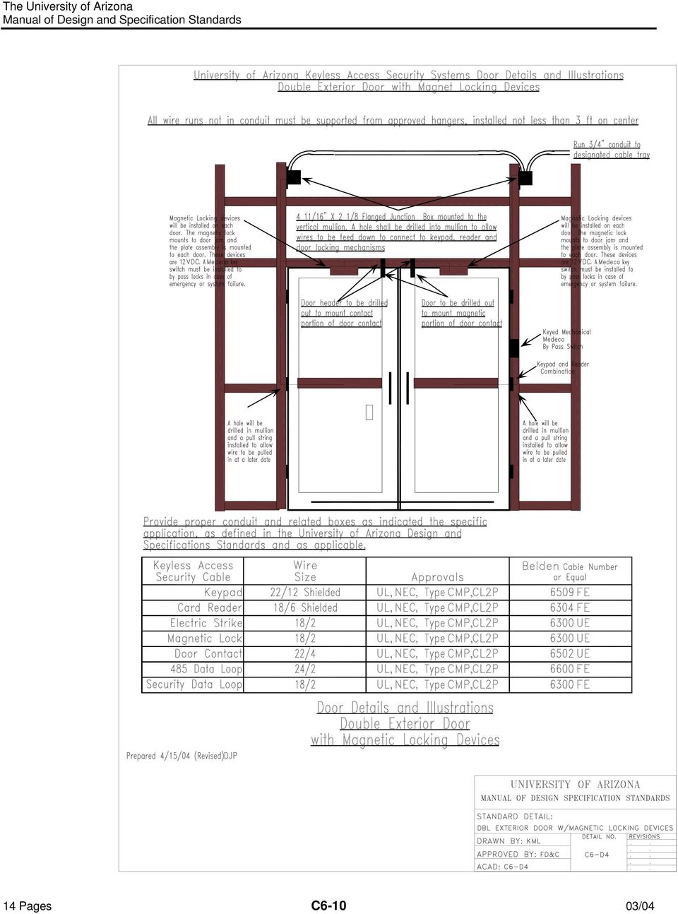
1 TAB C-6 KEYLESS ACCESS AND SECURITY SYSTEM GUIDELINE The University of Arizona has implemented a Keyless Access and Security System program to provide a cost effective, efficient, and maintainable means of providing and managing access into campus buildings for the university community, contractors and visitors. The focus of the system is to address issues of loss prevention, personal safety, and convenience through the use of this standardized technology. The system utilizes the University's CatCard as the "key" since it is universally deployed to all campus constituencies. The principle focus of the program addresses building perimeter access points. Most University facilities are unlocked during normal (and sometimes extended) business hours, during which time keys are not required to enter the building. However, when the buildings are supposed to be closed and locked, it is the program's intent to provide entry through the use of the University of Arizona CatCard rather than with the use of a physical key. In order to equip new university building with this system, project consultants will need to provide a design and produce construction documents that have the following accommodations for a keyless access and security system: RISER - A riser for the building s Keyless Access/Security System. This riser is required to be stacked vertically within a building to permit the Keyless Access/Security System to be wired from floor to floor HEAD END EQUIPMENT - Space and some utilities for the Keyless Access/Security System head end equipment directly adjacent to the riser. This particular equipment exists on only one floor of the building. This equipment also needs to be provided with three duplex 120VAC electrical outlets and one voice/data jack. FIELD DOOR CONTROLLER PANELS - Space and power for Keyless Access field door controller panels at various locations throughout the building as determined by the keyless access system design. These panels will require hardwired, 120VAC power. RACEWAYS - Conduit and junction boxes will need to be provided for routing certain portions of the Keyless Access/Security System local area network. Not all of the keyless access and security system wiring is required to be located in conduit. In very general terms, conduit is required between the equipment that is installed on walls up to accessible, above ceiling space or the building s cable tray. DOOR HARDWARE Designated doors will have hardware that needs to interface and/or be controlled by the Keyless Access system. Doors that have keyless access hardware requirements may either have their hardware specified and provided under the general construction contract (for example in the door hardware package) or have their hardware provided by Amer-X as part of the Keyless Access/Security System installation. DOOR FRAMES - Doorframes - pre-prepared from the manufacturer that can easily accommodate the addition of equipment for electronic operation. These frames typically include a handy box at the top of the doorjamb and a latch strike mud pocket that is deep enough for an electronic strike. Consultant shall coordinate door frame requirements during the design phase of a project. All the Keyless Access/Security System wiring is low voltage; only the head end equipment and field door controller panels require 120VAC. As such, most of the wiring is not required to be located in conduit. The Keyless Access/Security System is not required to be provided with emergency power; each building s system is provided with sufficient battery backup to provide at least four hours of standby operation. In the event a particular installation calls for longer standby power capability, the 120VAC power could be on an emergency circuit. The building Keyless Access/Security System communicates with the main server through phone and data lines; no connection to a hardwired network is necessary. 14 Pages C6-1 03/04

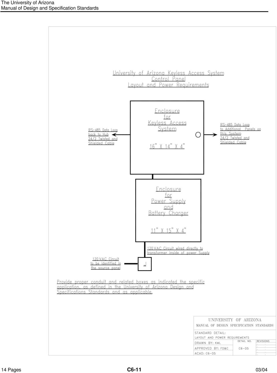
2 The following information is intended to explain the detailed requirements of each portion of the Keyless Access/Security System infrastructure that will need to be provided by under the general construction contract. RISER A minimum 2 riser for each major wing of the building. The riser must serve every occupied floor of a building. One 12 x12 x4 box at each floor (see Notes below). A 1 conduit from the riser box to the building s cable tray Notes: A building may only have one riser, but larger, more complex buildings may have more than one. Amer-X will provide the riser boxes for each floor of the building HEAD END EQUIPMENT Security Control Panel One 16 x16 x4 box for security control panel (see Notes below) One, duplex 12OVAC receptacle for panel power. This receptacle is not required to be on emergency circuit. The circuit for this receptacle is not required to be dedicated. One, voice/data jack with an RJ31X jack. The data side of this jack is used by the keyless access system panel. Notes: Installation of security system wiring and the phone line cord between control panel and voice/data jack is provided by Amer-X. 12OVAC-24VDC transformer and transformer cover for the power receptacle will be provided and installed by Amer-X. Amer-X receives the box for security panel from the equipment manufacturer. Amer-X will provide this box to the electrical contractor for installation during building construction. Keyless Panel and Network Connection One 16 x22 x6 box for keyless access panel and net connection (see Notes below) Two, duplex 12OVAC receptacles - one for keyless access panel power, one for the network connection power. This receptacle is not required to be on emergency circuit. The circuit for this receptacle is not required to be dedicated. One, voice/data jack with an RJ31X jack. The voice side of this jack is used by the security system panel. Notes: Installation of keyless access system wiring and the network connection cord between control panel and voice/data jack is provided by Amer-X. 12OVAC-24VDC transformers and transformer covers for the power receptacles will be provided and installed by Amer-X. Amer-X receives the box for keyless access panel from the equipment manufacturer. Amer-X will provide this box to the electrical contractor for installation during building construction. FIELD DOOR CONTROLLER PANELS Depending on the number and location of controlled doors, keyless access field door controller panels will need to be installed at various locations in the building. At each of these locations, the following equipment is required: One 16 x22 x6 box for the field door controller panel (see Notes below) 12OVAC power hardwired into the box. This circuit is not required to be dedicated or on emergency power. 14 Pages C6-2 03/04
 One, duplex 12OVAC")
3 Notes: The panels can be installed above ceilings, in equipment rooms, or other similar areas. The 16 x22 x6 holds the largest field controller panel. This size box may not be installed at every location, but space should be provided to accommodate the worst case box. Amer-X receives the boxes for the field controller panels the equipment manufacturer. Amer-X will provide these boxes to the electrical contractor for installation during building construction. RACEWAYS All of a building's perimeter access points will need to be provided with wiring pathway that will permit the doors to be controlled electronically. Each building perimeter access point shall be provided with the following equipment: Door Contacts Electronic Locking (either electric strikes or latches, or magnetic locks) Request to Exit Device In addition, certain, designated building entries (as determined by the Keyless Access/Security System design) shall be provided with the following additional keyless access equipment: Card reader PIN pad Raceways will need to be provided from accessible, above-ceiling spaces to this equipment at each door where this equipment is located. Notes If magnetic locks are used on a door, a keyed bypass switch will be required. This is an additional piece of equipment that will also require conduit to the accessible, above-ceiling space. For storefront-type entries, the Keyless Access/Security System wiring can be routed through the storefront mullions. This is a field installation coordination issue that Amer-X addresses with the storefront installers during construction. For all glass entries, a post or bollard will be required to mount some of the keyless access equipment (card reader, PIN pads). This type of installation requires greater consideration during the project s design phase. DOOR HARDWARE Electronic locking requires special hardware for the doors designated to be controlled by the Keyless Access/Security System. In general terms, there are three types of electronic locking hardware: electric strikes, electric latches, and magnet locks. Until the building s design reaches a point where the door types are well defined, it cannot be determined which type of electronic locking hardware will be used. However, the following should be considered: Magnetic locks are generally the most costly way to electronically lock a door. They should only be used when the other two alternatives are not feasible (i.e. double doors that require panic hardware and cannot have a mullion). Electric strikes can be installed in almost all doorframes or mullions and are the most economical way to electronically lock a door. Electronic latches are typically used where the door is required to remain positively latched (i.e. fire doors) in the event of a Keyless Access/Security System failure. DOOR FRAMES Installation of electronic locking on doors is facilitated by having doorframes pre-prepared from the manufacturer for electronic hardware and controls. This entails the following A handy box provided at the top of the door frame, located 6 inches off the latch side of the frame 14 Pages C6-3 03/04

4 KEYLESS ACCESS/SECURITY SYSTEM INSTALLATION As the University's sole source, keyless access and security systems vendor, Amer-X performs the following installation tasks associated with the keyless access and security system: Installation of head end and field panels in boxes installed by the electrical contractor Installation of 24VDC transformers and transformer covers on duplex receptacles installed by the electrical contractor Connection of power source to panels Connection of phone/data lines to jacks installed by the electrical contractor Coordination with construction trades, such as window and door installers, to facilitate installation of peripheral devices Installation of peripheral devices (door contacts, card readers, PIN pads, electric strikes, etc.) Installation of the low voltage Keyless Access/Security System wiring - both in conduits provided by electrical contractor (in walls and vertically through the building) and the data loop local area network wiring between panels and devices (routed similar to telecommunication lines through above ceiling spaces). DESIGN PHASE INVOLVEMENT Please refer to the following process descriptions and flow chart for how Amer-X should be involved in the design process. 14 Pages C6-4 03/04

5 DESIGN PHASE INVOLVEMENT, PROCESS AND FLOW CHART Schematic Design Consultant, User group, and Amer-X meet Introduction of keyless access/security system Review building layout, functions, different building constituencies, and expected building operation. See Note (1) below. Design Development Amer-X develops preliminary system design and budget. Submits copy to Project Coordinator, Consultant, and User group Consultant, User group, and Amer-X meet. Review preliminary design with user and consultant. Make modifications/deletions/additions as determined by refined understanding of building operations Amer-X develops final system design and budget. Submit copy to Project Coordinator, Consultant, and User group. Provides standard door details, riser diagram, door hardware requirements to consultants Construction Documents Amer-X verifies coordination of consultant documentation with final system design Construction Phase Electrical Contractor installs pathways (riser and door conduit) according to specifications Door contractor preps doors and jambs for equipment, according to specifications University establishes purchase order with Amer-X for system installation Amer-X coordinates field device installations with affected contractors Schematic Design Note (1): Amer-X meets with consultants and user group(s) after schematic design to introduce the keyless access/security system program, and describe the system's capabilities and options. This is where the dialog on how the users expect the building to operate from an access point of view begins. A review of the functions that take place in the building, the different user groups/constituencies, and any special concerns about asset protection, special activities (cash handling, pharmaceutical storage, etc.) and access management should also take place at this time. User groups will be asked to think about how they need and/or want the building to be accessed During normal business hours After normal business hours For special events User Groups will also be asked to think about who they need and/or want to be able to access the building when the building is: Normally open Supposed to be closed 14 Pages C6-5 03/04

6 14 Pages C6-6 03/04

7 14 Pages C6-7 03/04

8 14 Pages C6-8 03/04

9 14 Pages C6-9 03/04

10 14 Pages C /04
11 14 Pages C /04
12 14 Pages C /04

13 14 Pages C /04

14 14 Pages C /04

TAB C-6 KEYLESS ACCESS AND SECURITY SYSTEM GUIDELINE
 TAB C-6 KEYLESS ACCESS AND SECURITY SYSTEM GUIDELINE The University of Arizona has implemented a Keyless Access and Security System program to provide a cost effective, efficient, and maintainable means
CONSULTANT PROCEDURES & DESIGN GUIDELINES 28 13 00 ACCESS CONTROL SYSTEM
 GENERAL: To provide minimum standards for Access Control Systems. PART 1 Common Work Results for Access Control System 1.1 Owner will provide server and software for connecting control panels through the
Electrical. This section applies to the design and installation of building power distribution systems.
 Basis of Design This section applies to the design and installation of building power distribution systems. Design Criteria This section contains the architectural, structural and mechanical provisions
UBC Technical Guidelines Section 17900 2015 Edition Secure Access: General Standards Page 1 of 7
 Page 1 of 7 1.0 GENERAL 1.1 Related UBC Guidelines.1 Section 17910, 17920 and 17930.2 Section 17100 Cable Infrastructure Overview, sub sections 1.4.9 and 1.5.3 Section 17110 Communication Rooms, sub section
DIVISION 28 ELECTRONIC SAFETY AND SECURITY
 DIVISION 28 ELECTRONIC SAFETY AND SECURITY CENTRALLY MANAGED ELECTRONIC ACCESS CONTROL, VIDEO SURVEILLANCE, AND INTRUSION ALARM SYSTEMS 1. All questions on equipment approvals in this section shall be
DIVISION 28 ELECTRONIC SAFETY AND SECURITY
 DIVISION 28 ELECTRONIC SAFETY AND SECURITY CENTRALLY MANAGED ELECTRONIC ACCESS CONTROL, VIDEO SURVEILLANCE, AND INTRUSION ALARM SYSTEMS 1. All questions on equipment approvals in this section shall be
DARTMOUTH COLLEGE DESIGN January 3, 2012 & CONSTRUCTION GUIDELINES
 PART 1 DESIGN DIRECTIVES 1.1 OVERVIEW SECTION 13825 SECURITY MANAGEMENT SYSTEMS A. The access control, surveillance, and intrusion detection system implemented for use at Dartmouth College is a Lenel International
DENVER PUBLIC SCHOOLS DESIGN AND CONSTRUCTION STANDARDS This Standard is for guidance only. SECTION 17650 SECURITY SYSTEMS
 PART 0 DESIGN STANDARDS 0.01 GENERAL DESIGN GUIDELINES A. Inspections and observations by the Owner do not relieve the A/E of contract responsibilities. B. Chain of command 1. The DPS Project Manager is
DORMA MODEL PS-406BB POWER SUPPLY INSTALLATION INSTRUCTIONS
 Features: INSTALLATION Install in accordance with NFPA 70. DORMA MODEL PS-406BB POWER SUPPLY INSTALLATION INSTRUCTIONS Up to 1.95 Amps Load Capacity Class 2 Rated Outputs Overload, Over Voltage, and Short
Doc 10. UTM Standards: Card Access Security System
 Doc 10 UTM Standards: Card Access Security System 1. GENERAL... 2 1.1. GENERAL REQUIREMENTS.... 2 1.2. SUMMARY OF WORK INCLUDED... 2 1.3. OVERVIEW... 2 1.4. MANDATORY REQUIREMENTS... 3 1.5. ACCESS CONTROL
ACCESS CONTROL ENTERPRISE SYSTEM (ACES) CARD ACCESS DIVISION 17920.100, ISSUE # 4, JANUARY 21, 2015. http://maps.stanford.
 CARD ACCESS DIVISION 17920.100, ISSUE # 4, JANUARY 21, 2015. http://maps.stanford.") Page 1 of 30 ACCESS CONTROL ENTERPRISE SYSTEM (ACES) CARD ACCESS DIVISION 17920.100, ISSUE # 4, JANUARY 21, 2015 http://maps.stanford.edu/fdg_available ISSUE AUTHOR, DATE APPROVED BY, DATE EFFECTIVE DATE
Page 1 of 30 ACCESS CONTROL ENTERPRISE SYSTEM (ACES) CARD ACCESS DIVISION 17920.100, ISSUE # 4, JANUARY 21, 2015 http://maps.stanford.edu/fdg_available ISSUE AUTHOR, DATE APPROVED BY, DATE EFFECTIVE DATE
SECTION 13850 DETECTION AND ALARM
 SECTION 13850 DETECTION AND ALARM PART 1 GENERAL 1.01 SUMMARY A. Section Includes 1. Control Panel 2 Associated Equipment B. Products Installed But Not Supplied Under This Section 1. Section 16140 - Wiring
PLAN REVIEW GUIDE FOR FIRE ALARM
 PLAN REVIEW GUIDE FOR FIRE ALARM PROJECT NAME: PERMIT # PROJECT ADDRESS: CONTACT PERSON: PHONE Fire alarm system installation information shall be provided on the appropriate architectural and electrical
Minimum Standards for Data/Voice Infrastructure in New Building Construction
 UNIVERSITY OF WATERLOO Minimum Standards for Data/Voice Infrastructure in New Building Construction 12/17/2012 Offices 1. Two Work Area Outlets (WAO) on opposite walls, each with 2 jacks 2. Each WAO shall
Architectural. Access Control System - CAAMS
 Basis of Design The section applies to the design, rough-in, and installation of an "access control" system for building entrances/exits and for specified access control zones within a building. Campus
SECTION 17400 ACCESS CONTROL SYSTEM. CONDITIONS OF THE CONTRACT AND DIVISION 1, as applicable, apply to this Section.
 SECTION 17400 ACCESS CONTROL SYSTEM CONDITIONS OF THE CONTRACT AND DIVISION 1, as applicable, apply to this Section. PART 1 - GENERAL 1.1 RELATED WORK A. 16060 Grounding and Bonding B. 16070 Electrical
Middleborough Police Electronic Security Narrative
 Middleborough Police Electronic Security Narrative 1. PURPOSE The purpose of this document is to define specific security, access control and surveillance requirements for the exterior and interior of
Harris County Fire Code Electronic Lock Procedures
 Harris County Fire Code Electronic Lock Procedures Based on the current adopted edition of the International Building & Fire Code with Harris County Amendments For New Electronic Locking Systems March
Understanding Emergency Power Off (EPO)
") Understanding Emergency Power Off (EPO) White Paper #22 Executive Summary Emergency Power Off (EPO) is the capability to power down a piece of electronic equipment or an entire installation from a single
Understanding Emergency Power Off (EPO) White Paper #22 Executive Summary Emergency Power Off (EPO) is the capability to power down a piece of electronic equipment or an entire installation from a single
2. DESIGN REQUIREMENTS
 2. DESIGN REQUIREMENTS The Smart Lock Security system will give the user the ability to control his or her door lock from the convenience of texting from the user s cell phone. The device can be controlled
Security Systems Intrusion Alarm
 Dufferin-Peel Catholic District School Board STANDARD TEXT GUIDELINE FOR Security Systems for SECONDARY AND ELEMENTARY SCHOOLS Prepared by the Plant Department With Assistance from Vision Dynamics Formatted
This directive establishes Department of Homeland Security (DHS) policy regarding the physical protection of facilities and real property.
 policy regarding the physical protection of facilities and real property.") Department of Homeland Security Management Directives System MD Number: 11030.1 Issue Date: 04/21/2003 PHYSICAL PROTECTION OF FACILITIES AND REAL PROPERTY I. Purpose This directive establishes Department
Department of Homeland Security Management Directives System MD Number: 11030.1 Issue Date: 04/21/2003 PHYSICAL PROTECTION OF FACILITIES AND REAL PROPERTY I. Purpose This directive establishes Department
Section 010103 Summary of Work Contract 11-03 Security System, Network Infrastructure and UPS Power
 Section 010103 Security System, Network Infrastructure and UPS Power Part 1 General 1.1 Summary (Non-inclusive) A. Section Includes: Construction operations required by Contract Documents, defines aspects
SPACE TYPE: AUTOMATED DATA PROCESSING CENTER (ADP) (MAINFRAME)
 (MAINFRAME)") SPACE TYPE: AUTOMATED DATA PROCESSING CENTER (ADP) (MAINFRAME) Construction Criteria The unit costs for ADP Mainframe space types are based on the construction quality and design features in the following
SPACE TYPE: AUTOMATED DATA PROCESSING CENTER (ADP) (MAINFRAME) Construction Criteria The unit costs for ADP Mainframe space types are based on the construction quality and design features in the following
INSIDE TELEPHONE WIRING FOR Business
 Do It Yourself Guide INSIDE TELEPHONE WIRING FOR Business As of March 1, 2015 all single line business customers that have a demarcation point such as but not limited to a Network Interface Device (NID),
2301.1 Scope: Communications and Electronic Systems addressed in this section include:
 Chapter 23 COMMUNICATIONS / ELECTRONIC SYSTEMS SECTION 2301 - GENERAL 2301.1 Scope: Communications and Electronic Systems addressed in this section include: 1. Fire Alarm System 2. Telecommunication and
Engineers Edge, LLC PDH & Professional Training
 510 N. Crosslane Rd. Monroe, Georgia 30656 (770) 266-6915 fax (678) 643-1758 Engineers Edge, LLC PDH & Professional Training Copyright, All Rights Reserved Engineers Edge, LLC An Introduction to Communication
B. Related Sections: 1. Section 26 05 33 - Raceway and Boxes for Electrical Systems.
 SECTION 262726 - WIRING DEVICES PART 1 - GENERAL 1.1 SUMMARY A. Section includes wall switches; wall dimmers; receptacles; multioutlet assembly; and device plates and decorative box covers. B. Related
FIRE ALARM AND DETECTION SYSTEMS SECTION 16721
 PART 1 - GENERAL 1.01 WORK INCLUDED FIRE ALARM AND DETECTION SYSTEMS SECTION 16721 A. Provide a complete fully addressable, power limited, fire detection and evacuation system. The system shall be connected
NC State University Design and Construction Guidelines Division 26 Fire Alarm Systems
 NC State University Design and Construction Guidelines Division 26 Fire Alarm Systems 1.0 Purpose A. The following guideline provides the minimum standards and requirements for fire alarm systems. 2.0
QUESTIONS & ANSWERS. Re: Invitation for Bid #11-208 (West Covina DMV Cabling, Electrical, and Hardware Installation Services)
") STATE OF CALIFORNIA - BUSINESS, TRANSPORTATION AND HOUSING AGENCY DEPARTMENT OF MOTOR VEHICLES ADMINISTRATIVE SERVICES DIVISION P.O. BOX 932382 SACRAMENTO, CA 94232-3820 EDMUND G. BROWN JR., Governor QUESTIONS
STATE OF CALIFORNIA - BUSINESS, TRANSPORTATION AND HOUSING AGENCY DEPARTMENT OF MOTOR VEHICLES ADMINISTRATIVE SERVICES DIVISION P.O. BOX 932382 SACRAMENTO, CA 94232-3820 EDMUND G. BROWN JR., Governor QUESTIONS
INSTALLATION GUIDE. Card Reader & Controller with KIM Swipe Reader for Solitaire 850 / 950 / 850L Learnlok PK2930
 INSTALLATION GUIDE Card Reader & Controller with KIM Swipe Reader for Solitaire 850 / 950 / 850L Learnlok PK2930 Card Reader and Controller Model 3.5 with KIM Swipe Reader Table of Contents 1. Features..................................
INTRUSION DETECTION SYSTEM Section 281600
 PART 1 - GENERAL 1.1 RELATED DOCUMENTS A. Drawings and general provisions of the Contract, including General and Supplementary Conditions and Division 01 Specification Sections, apply to this Section.
CalMod Design-Build Electrification Services
 SECTION 28 16 00 INTRUSION DETECTION SYSTEM PART 1 - GENERAL 1.1 DESCRIPTION A. This section describes the detailed technical requirements for the Intrusion Detection System (IDS), where the Contractor
Building Telecommunications Infrastructure Requirements
 Building Telecommunications Infrastructure Requirements This page identifies specific requirements for the design of telecommunications infrastructure for buildings at Clemson University. (Revised October,
SECTION 16721 FIRE ALARM AND DETECTION SYSTEMS
 SECTION 16721 FIRE ALARM AND DETECTION SYSTEMS The equipment requirements of this section apply to the IUB Campus. The IUPUI Campus has a preferred vendor agreement for fire alarm systems. Contact Pat
Data Center Operational Policy
 POLICY NAME: Data Center Operational Policy Effective Date: Policy Owner: Policy Number: Related Policies: Purpose: Scope: Policy Statement: Definitions: Responsibilities: The policy will become effective
TECHNICAL QUESTIONS AND ANSWERS ITN-DOT-14/15-7009RM TAMPA OPERATIONS CENTER VIDEO SURVEILLANCE/SECURITY ACCESS SYSTEM
 TECHNICAL QUESTIONS AND ANSWERS ITN-DOT-14/15-7009RM TAMPA OPERATIONS CENTER VIDEO SURVEILLANCE/SECURITY ACCESS SYSTEM 1) Does the department have an estimate on the total number of cameras required and
Electrical for Detached Garages: Updated Feb 19, 2016 for 2015 CE Code in force Jan. 1, 2016. Underground branch circuit feeding a detached garage:
 Electrical for Detached Garages: Updated Feb 19, 2016 for 2015 CE Code in force Jan. 1, 2016 * Garage construction requires permits (electrical, building) * Permits must be applied for at the time. * Dial
FITNESS FACILITY WIRING SPECIFICATIONS. NETPULSE Inc. 2331 3rd Street San Francisco, CA 94107 Phone: 415.643.0223
 FITNESS FACILITY WIRING SPECIFICATIONS NETPULSE Inc. 2331 3rd Street San Francisco, CA 94107 Phone: 415.643.0223 CONTENTS: - Scope of work Summary - Equipment list - Technical specifications - Map of data
OPEN ITEMS LIST - CONSTRUCTION Project Name: East Central Middle School - Jackson County CLA#: 11003
 OPEN ITEMS LIST - CONSTRUCTION Project Name: East Central Middle School - Jackson County CLA#: 11003 No. Discipline Sent to Name Item Date Noted Date Resolved How item was resolved Electrical Contractor
Solar Panel Installations
 Solar Panel Installations Page 1 of 6 SINGLE-FAMILY RESIDENTIAL CHECKLIST City of Hayward Development Services Department Revised: 7-09-15 PERMIT REQUIREMENTS Permits are required for all solar panel installations.
Standard Comms Rooms Specification
 Standard Comms Rooms Specification Room Configuration Electrical General Distribution Boards Small Power Lighting Containment Fire Detection General To be defined in the project brief but should meet requirements
EQUIPMENT SPECIFICATIONS
 EQUIPMENT SPECIFICATIONS IC-1600 Intelligent Controller The IC-1600 Intelligent Controller is a fully intelligent panel that has a complete database on board. It operates in conjunction with the Access
Utility Distribution Systems
 Utility Distribution Systems 6/2012 A0011037 1 WARRANTY This equipment is warranted to be free from defects in materials and workmanship, under normal use and service, for a period of 12 months from date
INSTALLATION GUIDELINES for SOLAR PHOTOVOLTAIC SYSTEMS 1
 City of Cotati Building Division 201 W. Sierra Ave. Cotati, CA 94931 707 665-3637 Fax 792-4604 INSTALLATION GUIDELINES for SOLAR PHOTOVOLTAIC SYSTEMS 1 Any PV system on a new structures should be included
DESIGN GUIDELINES. Local Area Network
 DESIGN GUIDELINES Local Area Network The total oversight and management responsibilities for information assurance (IA) and protection of DoDEA s critical infrastructure fall under the purview of the DoDEA
AC-115 Compact Networked Single Door Controller. Installation and User Manual
 AC-115 Compact Networked Single Controller Installation and User Manual December 2007 Table of Contents Table of Contents 1. Introduction...5 1.1 Key Features... 6 1.2 Technical Specifications... 7 2.
Contractors Guide Central Inverter System Installation
 Contractors Guide Central Inverter System Installation Step By Step Procedures 2,200 Watt/VA 6 Step Installation 1. Mount Bottom Cabinet 2. Mount Top Cabinet 3. Install Batteries 4. Install Conduit 5.
FIRE ALARM SYSTEM. A. Shop drawings shall be submitted as follows: 1. Manufacturer's published literature. for aspproval.
 Polk School District Specifications for the New Fire Alarm in the Existing Building Eastside Elementary School FIRE ALARM SYSTEM 1.01 SUBMITTALS A. Shop drawings shall be submitted as follows: 1. Manufacturer's
SECTION 28 05 00 COMMON WORK RESULTS FOR ELECTRONIC SAFETY AND SECURITY
 SECTION 28 05 00 PART 1 - GENERAL 1.1 RELATED DOCUMENTS A. Drawings and general provisions of the Contract, including General and Supplementary Conditions and Division 01 Specifications Sections, apply
No Phone Line System. Quick Start Guide NPL II. 1.0 Installation
 Used in conjunction with EntraGuard Gold Telephone Entry Systems, the provides No Phone Line communication and door or gate control through existing building telephone lines without the need purchase phone
SECTION 13850 (28 31 00) FIRE DETECTION AND ALARM SYSTEM
 FIRE DETECTION AND ALARM SYSTEM") SECTION 13850 (28 31 00) FIRE DETECTION AND ALARM SYSTEM ENGINEERING SPECIFICATION INTELLIGENT REPORTING FIRE DETECTION SYSTEM PART 1 GENERAL 1.1 DESCRIPTION A. This specification includes the furnishing,
SECTION 13850 (28 31 00) FIRE DETECTION AND ALARM SYSTEM ENGINEERING SPECIFICATION INTELLIGENT REPORTING FIRE DETECTION SYSTEM PART 1 GENERAL 1.1 DESCRIPTION A. This specification includes the furnishing,
READ THIS MANUAL BEFORE PROCEEDING WITH THE INSTALLATION. FAILURE TO FOLLOW THE INSTALLATION INSTRUCTIONS MAY VOID YOUR WARRANTY!
 READ THIS MANUAL BEFORE PROCEEDING WITH THE INSTALLATION. FAILURE TO FOLLOW THE INSTALLATION INSTRUCTIONS MAY VOID YOUR WARRANTY! The main power to any existing system must be disconnected prior to the
Policy Title-Aquia Data Center Operational Policy & Procedure. Policy ID - TSD-ADC001. Version - Version: 1.0. Supersedes Version 1.
 Policy Title-Aquia Data Center Operational Policy & Procedure Policy ID - TSD-ADC001 Version - Version: 1.0 Supersedes Version 1.0 Review Date One (1) year from effective date. Policy & Procedure - Provides
Fire Alarm System Plans Submittal Guidelines For New and Existing Systems
 Fire Alarm System Plans Submittal Guidelines For New and Existing Systems SCOPE The Temecula Fire Prevention Bureau (TFPB) has established the following requirements for the submittal of all fire alarms,
HM-W536 Install Guide
 HM-W536 Install Guide 9/13/2013 IMPORTANT SAFETY INSTRUCTIONS Warning - When using electrical devices, basic safety precautions should be followed to reduce the risk of fire, electrical shock or injury.
Element D Services Electrical
 Service and PART 1 - GENERAL 1.01 OVERVIEW A. This Section includes design standards and requirements for electrical service and distribution. This is a design standard and is not intended to be used as
Presenters Brett Weiss, Gabe Martinez, Brian Kroeger.
 1 Presenters Brett Weiss, Gabe Martinez, Brian Kroeger. Topics to be covered: Cable identification Purpose of the various cable types Installation techniques Building Infrastructure Overview of networking
GROWTH MANAGEMENT DEPARTMENT 201 SE 3 rd ST, (Second Floor), Ocala, FL 34471 (352) 629-8421; FAX: (352) 629-8264
, Ocala, FL 34471 (352) 629-8421; FAX: (352) 629-8264") BUILDING CODE GUIDELINES FOR ELECTRICAL INSPECTIONS Building Code compliance is the obligation of design professionals and/or contractors. Plan Review and Inspection Guidelines are intended to be used
BUILDING CODE GUIDELINES FOR ELECTRICAL INSPECTIONS Building Code compliance is the obligation of design professionals and/or contractors. Plan Review and Inspection Guidelines are intended to be used
SECTION 08740 ELECTRO-MECHANICAL HARDWARE
 SECTION 08740 ELECTRO-MECHANICAL HARDWARE PART 1 - GENERAL 1.1 SUMMARY: A. Section Includes: 1. Items known commercially as electro-mechanical hardware, required for special applications at limited doors.
How To Plan Out An Array Of Solar Panels
 CITY OF DOWNEY COMMUNITY DEVELOPMENT, BUILDING AND SAFETY 11111 Brookshire Avenue Downey, CA 90241 562.904.7142 (www.downeyca.org) B SECTION 01/01/2011 EFFECTIVE DATE PHOTOVOLTAIC 032 FORM NUMBER 2013
Fire. The Fire Installers Mate. A guide to fire alarm systems design
 Fire The Fire Installers Mate A guide to fire alarm systems design BS 5839 Part 1:2002 A guide to BS 5839 Part 1:2002 Disclaimer This booklet is not intended to be a comprehensive guide to all aspects
Design Consultant (Electrical Services) Design Deliverables and Responsibilities Allocation (Stage E+)
 Design Deliverables and Responsibilities Allocation (Stage E+)") Design Consultant (Electrical Services) Design Deliverables and Responsibilities Allocation (Stage E+) 1. In addition to the information scheduled below, the pre-tender designer is responsible for: (i)
Design Consultant (Electrical Services) Design Deliverables and Responsibilities Allocation (Stage E+) 1. In addition to the information scheduled below, the pre-tender designer is responsible for: (i)
1. Furnish and install faceplate and modular jacks at each single gang outlet as described below:
 Washington University in St. Louis Building: Communication Specification: Research Voice/Network/Typical 1. Furnish and install faceplate and modular jacks at each single gang outlet as described below:
WIRELESS STATUS MONITOR
 INSTALLATION INSTRUCTIONS WIRELESS STATUS MONITOR (WSM or AUWSM) The most current version of this document is available for download at: http://www.ir-swa.com P/N: M053-032-D Schlage 245 W. Roosevelt Road,
Information and Communication Technology Network Cabling Infrastructure Standard
 Approved on Dec-2005 by Eugene Formato Manager, Communications Services Last Amended Aug-2009 by Jarren Beveridge Network Engineer, Communications Services Scheduled for Review Jan-2010 Information and
Quantec Wiring Instructions
 Approved Document No. DNUQ777 Rev Quantec Wiring Instructions GENERAL Quantec can be compared to a very sophisticated analogue addressable fire alarm system where the integrity of the wiring is of paramount
FLORIDA ATLANTIC UNIVERSITY FIRE ALARM SYSTEM INSTALLATION MANUAL
 FLORIDA ATLANTIC UNIVERSITY FIRE ALARM SYSTEM INSTALLATION MANUAL January, 2003 Environmental Health and Safety Florida Atlantic University 777 Glades Rd. Boca Raton, FL 33431 Phone: 561-297-3129 Fax:
Panic & emergency exit devices
 CFPA-E Guideline CFPA-E No 2:2007 - Appendix Appendix No: 1 Panic & emergency exit devices FOREWORD This Appendix offers technical solutions according to table 8.1 in the European Guide Line ""Panic &
466-1936 Rev E October 2004 ZZZ*(6HFXULW\FRP. Part No: 60-883-95R. CareGard. User Guide
 ) *(6HFXULW\ 466-1936 Rev E October 2004 ZZZ*(6HFXULW\FRP Part No: 60-883-95R CareGard User Guide FCC Notices FCC Part 15 Information to the User Changes or modifications not expressly approved by GE Security
TELECOMMUNICATIONS STRUCTURED CABLING GUIDELINES AND SPECIFICATIONS. University of Chicago IT Services Infrastructure Services October 2011
 TELECOMMUNICATIONS STRUCTURED CABLING GUIDELINES AND SPECIFICATIONS IT Services Infrastructure Services October 2011 Table of Contents 1 Introduction... 4 1.1 Planning and Design... 4 1.2.1 Roles and Responsibilities...
UNIVERSITY OF WASHINGTON Facilities Services Design Guide. Electrical. Metering and Monitoring. Basis of Design
 Basis of Design This section applies to the design, installation and integration of metering and monitoring equipment, including: hardware installed in the electrical service and distribution equipment,
Fire Alarm System Plans Review Checklist Property location Date of Review
 Fire Alarm System Plans Review Checklist Property location Date of Review 1. Is application completed in entirety? 2. Are the plans review fee submitted with the application? 3. Does floor plan include
Simon XT Installation Guide
 Simon XT Installation Guide This is the Installation Guide for the Simon XT control panel (models 600-1054-95R-11 and 600-1054-95R-11-CN). The system can monitor up to 40 sensors including: Door/Window
Georgia Tech Aerospace Server French building Server Room. Server Room Policy Handbook: Scope, Processes and Procedure
 Georgia Tech Aerospace Server French building Server Room Server Room Policy Handbook: Scope, Processes and Procedure Version History Version/Status Release Date Comments 1.1/Draft 1.2 1.3 1.4 1.5 1.6
SECURITY LATCH TM SIMPLE, SAFE & SECURE
 SECURITY LATCH TM SIMPLE, SAFE & SECURE WHAT IS SECURITY LATCH Security Latch is a simple, safe and secure method used to add extra security to your panic doors. Security Latch is designed to increase
Understanding Access Control
 Understanding Access Control To understand access control, we must understand the language of the industry. Terms like alarm inputs, relays, timezones, anti-passback, shunt, and access levels are commonly
Top Commercial / Residential Electrical Requirements *
 Department of Community Development Building Division 4800 West 92 nd Avenue Westminster, Colorado 80031 For Information call (303) 658-2075 Fax (303) 706-3922 www.westminsterpermits.com Top Commercial
800 Communications Circuits
 ARTICLE 800 Communications Circuits INTRODUCTION TO ARTICLE 800 COMMUNICATIONS CIRCUITS This article has its roots in telephone technology. Consequently, it addresses telephone and related systems that
Wireless Networks and Power Quality
 Will installing wireless networking change my back-up power requirements? What data do I need to know in order to determine my wireless network back-up power requirements? What other issues should I consider
DE Frame with C Series Sidelight
 TOOLS REQUIRED Tape measure 6' magnetic level 3' magnetic level Screw gun with clutch adjusted #2 phillips tip #3 phillips tip Screwdriver (used to adjust frame on will using oval slots) Pry Bar Powder
INSTALLATION INSTRUCTIONS
 LIGHTING CONTROL PANELS 4 AND 8 RELAYS INSTALLATION INSTRUCTIONS INSTALLATION OVERVIEW The installation instructions contained in this document are provided as a guide for proper and reliable installation.
TELECOMMUNICATIONS NETWORK STANDARDS AND GUIDELINES FOR THE NEW ADMINISTRATION BULDING
 TELECOMMUNICATIONS NETWORK STANDARDS AND GUIDELINES FOR THE NEW ADMINISTRATION BULDING October 1998 Table of Contents SECTION I: New Construction Programming 1.0 New Construction 1.1 Design Elements..................................
38. ACCESS CONTROL AND ELECTRONIC SECURITY SYSTEM
 38. ACCESS CONTROL AND ELECTRONIC SECURITY SYSTEM 38.1 GENERAL Scope Modification and extension of the existing CDU Cardax security system and CCTV System including: Cardax (FT 3000 series) Access control
System components portfolio overview. Power supplies, electromagnetic locks, electric strikes and system accessories
 System components portfolio overview Power supplies, electromagnetic locks, electric strikes and system accessories Our comprehensive commercial portfolio includes everything you need to hang, protect,
Physical Security. Paul Troncone CS 996
 Physical Security Paul Troncone CS 996 NSTISSI 4011 Building Construction Alarms Access Controls Information Systems Centers Personnel Security Tamper Resistance Goals of Physical Security Safeguard personnel
Scitex FB550 and FB750 Printers. Site Preparation Checklist
 Scitex FB550 and FB750 Printers Site Preparation Checklist 1 2015 Hewlett-Packard Development Company, L.P. The information contained herein is subject to change without notice. The only warranties for
ATTACHMENT F 050R6800016 - CABLE AND WIRING SERVICES FUNCTIONAL AREA I PRICE PROPOSAL FORM Amendment 6
 050R6800016 CABLE AND WIRING SERVICES (Column A) (Column B) (Column C) (Column D) (Column E) (Column F) (Column G) (B+C+D+E)*F= G Item Description PER 100' RUN PER 150' RUN PER 200' RUN PER 300' RUN QUANTITY
SECTION 16720 - FIRE AND SMOKE ALARM SYSTEM. City of San Diego, CWP Guidelines
 PART 1 -- GENERAL 1.1 WORK OF THIS SECTION SECTION 16720 - City of San Diego, CWP Guidelines A. The WORK of this Section includes providing manual and automatic fire alarm and smoke detection systems meeting
INDUSTRIAL AND COMMERCIAL SERVICE TRANSFORMER & METERING INSTALLATION SPECIFICATION
 INDUSTRIAL AND COMMERCIAL SERVICE TRANSFORMER & METERING INSTALLATION SPECIFICATION February 2013 NOTE: If conflict exists between St. Thomas Energy s Conditions of Service and this document, the Conditions
ELECTRICAL INSPECTION BULLETIN (Effective 2000-03-01)
") ELECTRICAL INSPECTION BULLETIN (Effective 2000-03-01) Rule 28-900 Standby Generator Installations Due to the increasing number of standby generator installations being established to maintain continuity
ELECTRICAL INSPECTION BULLETIN (Effective 2000-03-01) Rule 28-900 Standby Generator Installations Due to the increasing number of standby generator installations being established to maintain continuity
DEPARTMENTAL REGULATION
 U.S. DEPARTMENT OF AGRICULTURE WASHINGTON, D.C. 20250 DEPARTMENTAL REGULATION SUBJECT: Service Center Technology Modernization Project (SCTMP) Wiring/Cabling Specifications for Service Center Agencies
OCAD UNIVERSITY 7th FLOOR
 7th FLOOR KEY PLAN AREA IN CONTRACT, 30 RICHMOND STREET WEST CONTENT ISSUED FOR DATE FILE No. ELECTRICAL DRAWINGS RE-PERMIT/TENDER NOVEMBER 04, 015 AE- 15180-DRAW-E001-E005-R01 KEYPLAN AND DRAWING LIST