OPERATION & MAINTENANCE MANUAL. for 5 X 3 MAC - 5 X 4 MAC DOUBLE SUCTION SPLIT CASE PUMPS
|
|
|
- Christian Hodges
- 10 years ago
- Views:
Transcription
1 OPERATION & MAINTENANCE MANUAL for 5 X 3 MAC - 5 X 4 MAC DOUBLE SUCTION SPLIT CASE PUMPS PATTERSON PUMP COMPANY A SUBSIDIARY OF THE GORMAN-RUPP COMPANY PO Box Ayersville Road Toccoa, Georgia Telephone:

2 SAFETY PRECAUTIONS WARNING Do not operate this equipment neither in excess of its rated speed or other than in accordance with the instructions contained in this manual. The equipment has been found satisfactory of the conditions for which it was sold, but its operation in excess of these conditions may subject it to stresses and strains which it was not designed to withstand. For equipment covered by this instruction book, it is important to observe safety precautions to protect personnel from possible injury. Among the many considerations, personnel should be instructed to: avoid contact with rotating parts avoid bypassing or rendering inoperative any safeguards or protective devices avoid extended exposure in close proximity to machinery with high noise levels use proper care and procedures in handling, lifting, installing, operating and maintaining the equipment do not modify this equipment consult factory if modification is deemed necessary do not substitute for repair parts which can be provided by the equipment manufacturer. Safe maintenance practices with qualified personnel are imperative. Failure to heed this warning may result in an accident causing personal injury.

3 TABLE OF CONTENTS SECTION I: SECTION II: SECTION III: SECTION IV: SECTION V: SECTION VI: General Information...1 Storage & Protection...1 Installation 3-1 Location Foundation Mounting Alignment Grouting Piping...6 Operation 4-1 Starting Shutdown Minimum Flow Limitation...9 Maintenance 5-1 Lubrication Stuffing Box Wear Ring Clearance...11 Repairs & Replacement 6-1 To Remove Rotor Disassembly of Rotating Element To Remove Impeller Rings Inspection Assembly...18 Locating Operation Difficulties Recommended Spare Parts...21

4 SECTION I GENERAL INFORMATION This manual covers the installation, operation and maintenance of Patterson Pump horizontal split case pumps. The pump is a centrifugal, single stage, double suction type. When properly installed and when given reasonable care and maintenance, centrifugal pumps should operate satisfactorily for a long period of time. Centrifugal pumps use the centrifugal force principal of accelerating the liquid within a rotating impeller, and then collecting it and converting it to pressure head in a stationary volute. The pump consists of two assemblies: 1. Casing assembly or stationary part 2. Rotating element or moving part This casing is split along the horizontal centerline of the pump shaft, suction and discharge nozzles both being located in the lower half. With this arrangement, it is not necessary to disconnection suction or discharge piping to make repairs to, or replacement of the rotating element. Upper and lower half casings are bolted together and doweled to maintain a smooth volute contour inside the pump. Supporting feet are integrally cast in the lower half casing and are drilled for bolting and doweling to base plate. Bearing brackets form a drip pocket for collecting stuffing box leakage and are provided with drilled and tapped connections for draining. The brackets also contain an overflow hole to release the water before it reaches the shaft, in case drain piping should become clogged. Suction and discharge flanges are drilled and tapped for gauge connections. Pump suction and discharge nozzles are drilled and tapped on the underneath side for complete pump drain. Wear rings are provided to minimize internal bypassing of the liquid being pumped, and to better efficiency, as well as to reduce the replacement of major components (such as casing and impeller). SECTION II STORAGE & PROTECTION All pumps are shop serviced and ready for operation when delivered, but there is occasions when considerable time elapses between the delivery date and the time the pump is put into operation. Equipment, which is not in service, should be kept in a clean, dry area. If equipment is to be stored for long periods of time (six months or more), the following precautions should be taken to insure that the equipment remains in good condition. 1. Be sure that the bearings are fully lubricated. 2. Unpainted-machined surfaces, which are subject to corrosion, should be protected by some corrosive resistant coating. 3. The shaft should be rotated 10 to 15 revolutions by hand periodically in order to spread the lubricant over all the bearing surfaces. Suitable intervals are from one to three months, depending on atmospheric conditions, etc. In order to insure that the pump shaft does not begin to sag, do not leave the shaft in the same position each time. 1

5 Section II Storage & Protection Continued 4. Space heaters on motors and controllers should be connected and fully operable if atmospheric conditions approach those experienced in operation. Consult instruction manuals for other precautions concerning storage of individual components of pumping unit. 5. Fresh lubricant must be applied to bearings upon removal of equipment form storage. 3-1 Location: SECTION III INSTALLATION Several factors should be considered when selecting a location for the pumping unit (pump, base, drive, and coupling). The unit should be accessible for both inspection and maintenance. Headroom should be provided for the use of crane, hoist or other necessary lifting devices. The pump should be located as close as possible to the liquid supply so that the suction line is short and direct. Location should require a minimum of elbows and fittings in the discharge line to minimize friction losses. The unit should be protected against flooding. 3-2 Foundation: The foundation should be sufficiently substantial to absorb vibration and to form a permanent rigid support for the base plate. Concrete is most widely used for foundation. Before pouring the foundation, locate anchor bolts per outline drawing. Allow for 3/4 inch to 1 1/2 inch of grout between foundation and base plate. The top surface of the foundation should be roughened to provide a good bond for the grout. 3-3 Mounting: WARNING!!! Do not attempt to lift entire unit using lugs provided on either pump or motor only. Such action may lead to failure of the lugs and possible damage to the unit or injury to personnel. Lift unit with slings around the base plate, or by attaching cables to the lifting lugs on both the pump and the motor. Coupling halves should be disconnected when mounting the pumping unit on the foundation. Wedges should be used to support the unit at the time of grouting. Wedges should be located adjacent to anchor bolts (one on each side of bolt) and midway between bolts. Adjust the wedges to raise or lower the unit as required to align suction and discharge flanges to piping and to level the base plate. Leveling bolts made of cap screws and nuts are useful when leveling large base plate, but should not replace shims or blocks for supporting the load. After unit has been in operation for about a week, check alignment. After making any required adjustments, dowel pump and motor to base. 2

6 Section III Installation Continued 3-4 Alignment: Complete pump units are aligned at the factory, but all base plates are flexible to some degree, and therefore, cannot be relied upon to maintain alignment. Reliable trouble-free and efficient operation of a unit depends upon correct alignment. Misalignment may be the cause of noisy pump operation, vibration, premature bearing failure, or excessive coupling wear. Factors that may change the alignment of the pumping unit are settling of the foundation, springing of the base plate, piping strains, settling of the building, bearing wear, loose nuts or bolts on the pump or drive assembly, and a shift of the pump or drive on the foundation. When checking coupling alignment, remember, flexible couplings are not intended to be used as universal joints. The purpose of a flexible coupling is to compensate for temperature changes and to permit end movement of the shafts without interference with each other. Two types of misalignment may exist: parallel misalignment and angular misalignment. Limits of misalignments are stated in the coupling manufacturer's instructions, but should be kept to a minimum for maximum life of equipment components. To check coupling alignment, the following procedure should be followed: 1. Set the coupling gap to the dimension shown on the outline drawing. 2. Check for parallel misalignment by placing a straight edge across both coupling halves at four points 90 apart. Correct alignment occurs when the straight edge is level across the coupling halves at all points. 3. Check angular misalignment with a feeler gauge at four points 90 apart. Correct alignment occurs when the same gauge just enters between the halves at all four points. Angular and parallel misalignment are corrected by shifting the motor and adding or removing shims from under the motor feet. After each change, it is necessary to recheck the alignment of the coupling halves. Adjustment in one direction may disturb adjustment already made in another direction. An alternative method for checking coupling alignment is by use of a dial indicator. Proceed as follows: 1. Scribe index lines on coupling halves or mark where the indicator point rests. 2. Set indicator dial to zero. 3. Slowly turn both coupling halves so that the index lines match, or the indicator point is always on the mark. 4. Observe dial reading to determine whether adjustments are needed. Acceptable alignment occurs when total indicator reading does not exceed inches for both parallel and angular alignment. The importance of correct alignment cannot be overemphasized. corrected as required after: Alignment should be checked and 1. Mounting 2. Grouting has hardened 3. Foundation bolts are tightened 4. Piping is connected 5. Pump, driver, or base plate is moved for any reason. 3

7 WARNING!!! The importance of correct alignment cannot be overemphasized. The following procedure should be used for initial installation. 1. Place complete pump assembly on anchor bolts allowing room under the base plate for leveling wedges or shims. Make sure the base plate is level by using the leveling wedges adjacent to the foundation bolts and midway between the bolts. 2. Put nuts on the anchor bolts and tighten evenly, but not too tight. 3. At this point check alignment of the coupling. This should not be more than that recommended by the coupling manufacturer. 4. If misalignment is evident, determine which direction the coupling needs to be moved. 5. Loosen all nuts and add the shims underneath the base plate at the opposite corners. Use the anchor bolts to flex the base plate to bring the coupling into alignment. 6. After the alignment has been made with all anchor bolt nuts tight, the grouting can take place. 7. After grouting is completed, final alignment should be checked to be sure it is within allowable tolerances. Alignment should be checked and corrected as required after: - Mounting - Foundation bolts are tightened - Grouting has hardened - Piping is connected - Pump, driver, or base plate is moved for any reason 4

8

9 3-5 Grouting: Grout compensates for unevenness in the foundation and distributes the weight of the unit uniformly on the foundation. It also prevents lateral shifting of the base plate and reduces vibration. Use a nonshrinking grout. Foundation bolts should be tightened evenly, but not too firmly. Grout the unit as follows: 3-6 Piping: 1. Build a strong form around the base plate to contain the grout. 2. Soak the foundation top thoroughly, and then remove surface water. 3. Pour grout. Tamp liberally while pouring in order to fill all cavities and prevent air pockets. The space between the foundation and base plate should be completely filled with grout. In order to prevent the base plate from shifting, fill under the base plate at least four inches in from all four edges. Wedges may be left in place. 4. After the grout has hardened (usually about 48 hours), thoroughly tighten foundation bolts and check alignment. 5. Approximately 14 days after the grout has been poured or when it is thoroughly dry, apply an oil base paint to exposed edges of the grout to prevent air and moisture form coming in contact with the grout. Connect pipelines after the grout has thoroughly hardened. The suction and discharge piping should be installed with the shortest and most direct runs. Elbows should preferably be of the long radius type. Pipes must line up naturally. The piping must never be pulled into position by the flange bolts. Such action may draw the pump out of alignment. Pipes should be support independently of the pump so as not to put any strain on the pump casing. Suction piping, if not properly installed, is a potential source of faulty operation. Suction lines should be free of air leads, and arranged so there are no loops or high spots in which air can be trapped. Generally, the suction line is larger than the pump suction nozzle, and eccentric reducers should be used. Eccentric reducers are not necessary for bottom suction pumps. If the liquid supply is located below the pump centerline, the reducer should be installed with the straight side up. Most often air enters the suction pipe entrained in the liquid. Installations with a static suction lift preferably should have the inlet of the vertical suction piping submerged in the liquid to four times the piping diameter. A large suction pipe will usually prevent the formation of vortexes or whirlpools, especially if the entrance is flared (Figure 5). A floating vortex breaker (raft) around the suction piping may be provided if a tendency appears for a vortex to form at the liquid surface. A stream of liquid falling into the sump near the intake pipe will churn air into the liquid (Figure 6). The supply line should extend down into the sump. Liquid supply entering a well perpendicular to the intake line tends to rotate the liquid, which interferes with the flow into the suction line (Figure 7). A baffle placed in front of the supply pipe will remedy this situation. A short elbow should never to bolted directly to the pumps suction nozzle. The disturbance in the flow caused by the sharp bend so near the pump inlet may result in noisy operation, loss in efficiency, and capacity, and heavy end thrust. A long sweep or long radius elbow placed as far away from the pump as practicable should be used if a bend is necessary in the suction line. If separate suction lines cannot be used for each pump, then a tapering header with Y-branches should be used (Figure 8A). A straight branch header should never be used. Prior to installing the pump, suction piping and pump should be inspected internally, cleaned and flushed. If a strainer is installed in the suction line, the openings in the screen must be checked and cleaned periodically. The opening must be smaller than the sphere size allowed by the impeller. 6

10

11 Section III 3-6 Piping Continued Discharge piping should be installed with check valve and gate valve, with the check valve being between the pump and the gate valve. The check valve prevents reverse flow and protects the pump from excessive backpressure. The gate valve is used to isolate the pump for maintenance, priming and starting. If a diffuser is used, it should be placed between the pump and check valve. Stuffing box seal connections are usually made form the top of the pump casing. If the liquid being pumped is unsuitable for sealing, then it is preferable to bring fresh, cool water to seal connections from an outside source. Centrifugal separators or other filters may be used to remove abrasive particles from the liquid being pumped if an outside source is not available. After all piping connections have been made, the alignment should be checked again. SECTION IV OPERATION Before bolting the coupling halves together, check the drive rotation to see that it matches the pump rotation. Pump rotation is indicated by an arrow attached to the casing assembly. For a three-phase motor, rotation may be reversed, if necessary, by interchanging any two of the three power leads. Rotation of single-phase motors is fixed by internal wiring. WARNING!!! Prior to startup, check the coupling alignment as covered in the Installation Section. Operation of the pump with the unit misaligned will cause damage to the shaft, bearings, and the coupling. 4-1 Starting: When possible, turn the pump shaft by hand to insure that the parts do not bind Check the bearing lubricant Open the valve in the pump suction line, if fitted Close discharge valve Prime the pump in one of the following ways: 1. If the pump operates under positive pressure, open vent valve on top of the pump casing. After all entrained air has escaped, close the vent valves. Rotate the shaft, if possible, to allow any air trapped in the impeller passages to escape. 2. If the pump operates on a suction lift and a foot valve is included in the system, fill the pump and the suction line with liquid from an outside source. Trapped air should be allowed to escape through the vent valve while filling. 3. If the pump operates on a suction lift and no foot valve is provided, use a vacuum pump or ejector operated by air, steam, water, etc. to evacuate air from the pump case and suction line by connecting the ejector to the priming connection on top of the pump case. 8

12 Section IV Starting Continued Open valves in stuffing box seal lines, if fitted. Start driver. Open discharge valve slowly when the pump is up to speed. CAUTION: Overheating and/or loss of prime will result if the pump is operated against a closed valve for more than a few minutes. WARNING!!! The coupling guard should be in place when the unit is started. Stay clear of any exposed rotating parts while the pump is operating. Contact with rotating parts may result in injury to personnel. Adjust the packing gland until there is a slight leakage from the stuffing box. (See Maintenance on Adjustment of Packing). Mechanical seals need no adjustment. There should be no leakage. NOTE: Should the pump fail to build up pressure or discharge water when the discharge valve is opened, stop the pump and read Section Locating Operating Difficulties. 4-2 Shutdown The pump may be stopped with the discharge valve open without causing damage. However, in order to prevent water hammer effects, the discharge valve should be closed first. 1. Close discharge valve. 2. Stop driver. 3. Close water seal valves. 4. Close valve in the pump suction line, if fitted. If danger of freezing exists, drain the pump completely. 4-3 Minimum Flow Limitation All centrifugal pumps have limitations on the minimum flow at which they should be operated. The most common limitation is to avoid excessive temperature buildup in the pump because of absorption of the input power into the pumped fluid. Other less understood reasons for restrictions are: 1. Increased radial reaction at low flows in single volute casings. 2. Increased NPSHR at low flows. 3. Noisy, rough operation and possible physical damage due to internal recirculation. 4. Increased suction and discharge pulsation levels. The size of the pump, the energy absorbed, and the liquid pumped are among the considerations in determining these minimum flow limitations. For example, most small pumps such as domestic home circulators, service water pumps, and chemical pumps have no limitations, except for temperature buildup considerations while many large, high horsepower pumps have limitations as high as 40-50% of the best efficiency point capacity. The minimum safe flow for this pump is given under Pump Specifications. 9
. Mechanical seals need no adjustment. There should be no leakage.")
13 SECTION V MAINTENANCE 5-1 Lubrication: Couplings: Bearings: Couplings with rubber drive elements do not require lubrication. Most other couplings require some form of lubrication. Consult manufacturer's instructions for recommendations. Frequency of lubrication depends upon operating conditions and environment, therefore, lubrication intervals must be determined by experience. Table I may be used as a general guide for grease relubrication. Lubricants need replacing only because of contamination by dirt or dust, metal particles, moisture or high temperature breakdown. A small amount of grease may be added about every 400 hours of operation. The bearing housing should be about 1/3 full of grease. Oil lubricated units are provided with constant level oilers. Bottles should be kept filled at all times so that there is a visible supply of oil. All lubricants have a tendency to deteriorate in the course of time, therefore, sooner or later it will be necessary to replace the old lubricant with new. Bearings, which are dismantled, are, of course, much more easily cleaned than bearings, which stay in assembled equipment. Solvents may be used more freely and effectively. For cleaning bearings without dismounting, hot light oil at F may be flushed through the housing while the shaft is slowly rotated. Light transformer oils, spindle oils, or automotive flushing oils are suitable for cleaning bearings, but anything heavier than light motor oil (SAE 10) is not recommended. The use of chlorinated solvents of any kind is not recommended in bearing cleaning. Grease Relubrication: (pumps are shipped with grease in bearing housings) 1. Thoroughly clean grease fitting and outside of bearing housing. 2. Remove drain plug. 3. Inject clean, new grease forcing out the old. 4. Start and run the pump for a short time to eject any excess grease. 5. Wipe off all excess grease and replace drain plug. Oil Relubrication: (pumps are shipped without oil in bearing housing) 1. Remove drain plug and allow any residue oil to completely drain. 2. Remove constant level oiler bottle and clean thoroughly. 3. Replace drain plug. 4. Fill bottle, screw it to the lower reservoir of oiler and allow oil to flow into bearing housing reservoir. Repeat this procedure until a supply of oil remains in the bottle. For ball bearings, the oil level should be at about the middle of the lower most ball. For ring oiled sleeve bearings, the oil level should be about 1/8 inch over the lowest point of the oil ring. WARNING!!! Proper lubrication is essential to the pump operation. Do not operate the pump if sufficient lubricant is not present in the bearing housing of if lubricant is contaminated with excessive dirt or moisture. Operation of the unit under these conditions will lead to impaired pump performance, and possible bearing failure. Do not operate the pump with excessive amount of lubricant. Such action will cause bearings to overheat. 10

14 5-2 Stuffing Box: The purpose of a stuffing box is to limit or eliminate leakage of the pump fluid and to prevent air from entering the suction spaces along the pump shaft. Pumps are equipped with packing (limited leakage) or mechanical seals (no leakage). Normally, the pumped liquid is used to lubricate the stuffing box seal. If the liquid is dirty, gritty, or contains material that would gum or jam the seal, use a sealing liquid from an external source. If suction pressure is above atmospheric pressure, seal piping may not be required. For pumps equipped with packing, there must always be a slight leakage from the glands. The amount of leakage is hard to define, but we recommend a steady dripping of liquid through the gland. Stuffing box glands should be adjusted after the pump is started. When leakage is excessive, tighten gland bolts evenly a little at a time. Allow an interval for packing to adjust to new position. Never tighten gland to be leakproof, as this will cause overheating and undue wear on shaft sleeves. Replace stuffing box packing as follows: 1. Shutdown the pump. 2. Take precautions to prevent the driver from being inadvertently started. 3. Remove the gland bolt nuts and gland. 4. Remove and discard old packing rings note location of lantern ring. When repacking stuffing box, lantern ring must be positioned such that the water seal connection is opposite lantern ring. 5. Clean out the stuffing box. 6. Inspect shaft sleeve for wear if it is scored or grooved, it should be replaced. 7. Make sure the stuffing box bushing (if furnished) is set at the bottom of the box. 8. Insert rings of packing and tap lightly to seat against bushing. Be sure rings are of the proper size and length and installed with cuts staggered. Lantern ring must be installed opposite sealing water connection. 9. Install gland and tighten, finger tight. With the pump running, adjust gland as described previously. Care should be taken during the first hour of operation to take up on the packing gradually just enough to maintain the required amount of leakage. If the pump is operated daily, the stuffing box packing should be renewed about every two to three months before it gets hard and scores the shaft sleeves. Mechanical seals should be removed, assembled, and/or adjusted according to the seal manufacturer's instructions. There should be no leakage from the gland if mechanical seals are used, except for a brief run in period. 5-3 Wear Ring Clearance: Running fits between wear rings is given under the pump specifications. When these clearances are doubled, or the capacity of the pump is reduced by 5 to 10%, the rings should be renewed. The purpose of these rings is to keep internal bypassing of the liquid being pumped to a minimum. Clearances should be checked periodically and whenever the pump casing is opened. Check with feeler gauge or by direct measurement. Measure ID of case ring and OD of impeller ring, then compute clearance (ID minus OD). 11

15 TABLE 1 SUGGESTED RE-LUBRICATION INTERVALS FOR VARIOUS ENVIRONMENTAL, OPERATING AND TEMPERATURE CONDTIONS (GREASE LUBRICATED BEARINGS) AMBIENT CONDITIONS OPERATING CONDITIONS BEARING OPERATING TEMPERATURE SUGGESTED GREASING INTERVALS** USE THESE GREASES Dirt Clean Moderate to dirty Moisture Dry Dry Load Light to medium Light to medium Speed Slow to medium Slow to medium Low 0 F (-18 C) 120 F (49 C) 0 F (-18 C) 120 F (49 C) High 120 F (49 C) 200 F (93 C) 120 F (49 C) 200 F (93 C) 2 to 6 months 1 to 2 months 1 to 4 weeks 1 to 7 days High quality NGLI No. 1 or 2 multipurpose bearing greases are generally satisfactory. Consultation with a reputable lubricant supplier is recommended. Extreme dirt Dry Light to medium Slow to medium 0 F (-18 C) 200 F (93 C) Daily flushing out dirt High humidity Direct water Splash Light to heavy Slow to medium 32 F (0 C) 200 F (93 C) 1 to 4 weeks grease at shutdowns Lithium or other corrosion control grease Heavy to very heavy Slow 0 F (-18 C) -20 F (-29 C) 200 F (93 C) 120 F (49 C) 1 to 8 weeks 1 to 8 weeks High viscosity lubrication Light High speed 100 F (38 C) 200 F (93 C) 1 to 8 weeks Channeling (high speed) type grease Possible frost Light to heavy Slow to medium -65 F (-54 C) +250 F (121 C) 1 to 4 weeks grease at shutdown Wide temperature range Diester-type greases (Silicone-Diester- Polyester lubricants) Clean to moderate Dry Light to medium Slow to medium 80 F (27 C) 250 F (121 C) 1 to 8 weeks Good quality high temperature type greases Clean to dirty Dry Light Slow 80 F (27 C) 300 F (149 C) 1 to 4 weeks Synthetic type greases **Suggested starting interval for maintenance program. Check grease conditions for oiliness and dirt and adjust greasing frequency accordingly. Watch operating temperatures as sudden rises may show need for grease or indicate over lubrication on higher speed applications. 12

16 TABLE II RECOMMENDED GREASES Use NLGI Grade 2 grease Such As: COMPANY Texaco GREASE Premium RB No.2 Shell Alvania No. 2 Gulf Gulfcrown No. 2 Texaco Multifak No. 2 Standard Amolith No. 2 Sinclair Litholine Industrial No. 2 Cities Service H 2 Fina Lithium 2 - R WARNING!!! Use of lubricants other than those listed or their equivalent will cause reduced pump performance and reduce bearing life. 13

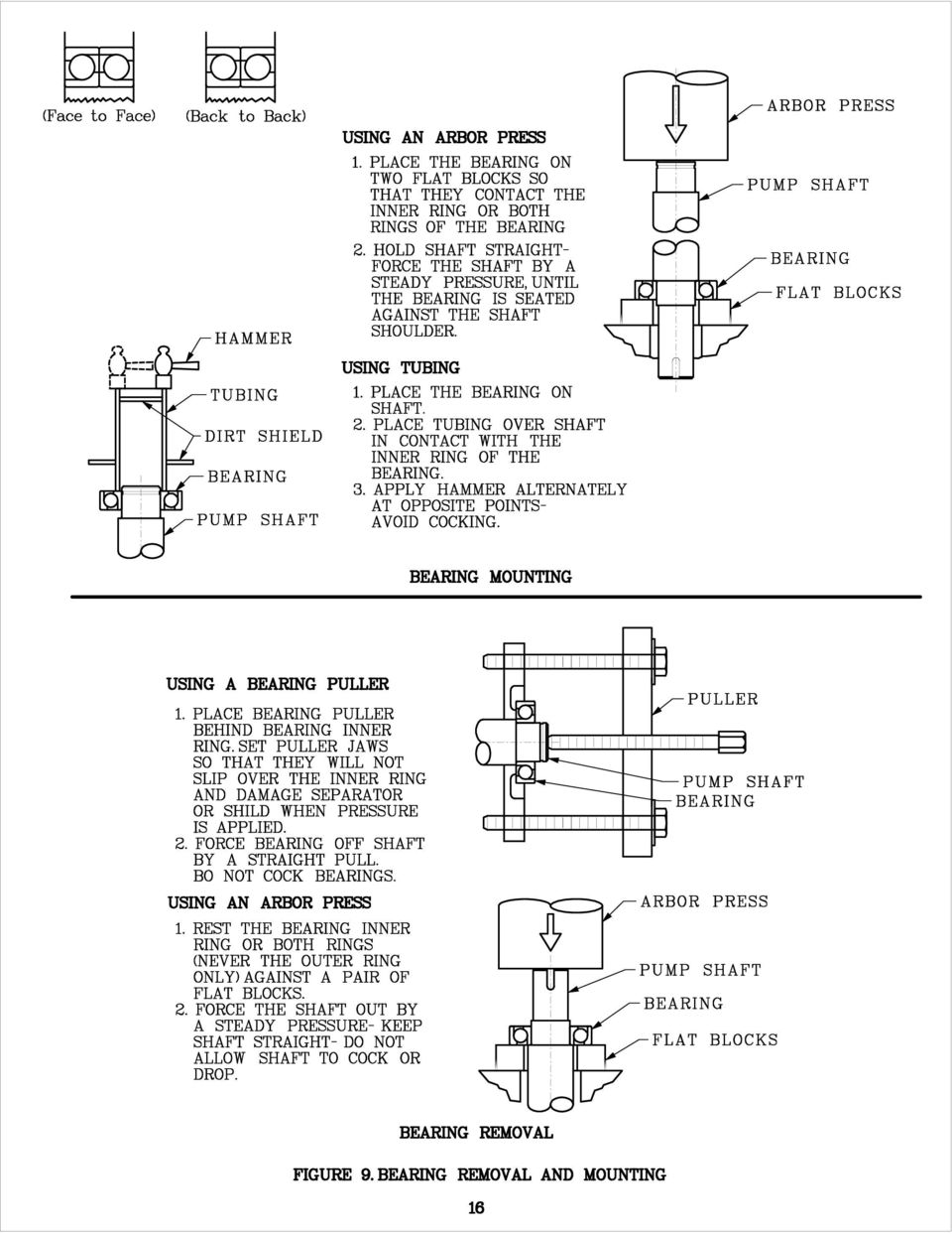
17 SECTION VI REPAIRS AND REPLACEMENT WARNING!!! Whenever any disassembly work is to be done on the pump, disconnect the power source to the driver to eliminate any possibility of starting unit. 6-1 To Remove Rotor: Reference: Pump Assembly Section 1. Remove the coupling guard and disconnect coupling halves. 2. Disconnect any piping from the upper half casing (1B) that will interfere with its removal. 3. Remove bolting from the casing flanges and the bearing caps (41). 4. Use lugs provided, lift upper casing (1B) straight up until clear of impeller. 5. Remove bearings caps (41). 6. Remove glands (17) and gland bolts. 7. Place slings around the shaft near the bearing housing and lift rotating element from lower casing (1A). 8. Place rotating element in a clean, dry work area for necessary disassembly. Case wear rings (7) will be loose on the rotating element. 6-2 Disassembly of Rotating Element: If the bearing assemblies do not require attention, but just the impeller or rings, then work just one side of the unit (impeller may be removed from either end). 1. Remove the pump half coupling. 2. Slide deflectors (40) toward center of pump. 3. Remove fasteners from bearing covers (35) and separate covers from bearing housings (31 & 33). NOTE: On model 5 x 3 MAC the bearing cover (123) at the outboard bearing is held by a retaining ring (172), which must be removed. On this model, then remove the retaining ring (171) holding the outboard bearing (18). 4. Remove bearing housings (31 & 33). NOTE: On model 5 x 3 MAC the bearings (16 x 18) are removed with the housings and a puller should be used. NOTE: Steps 5 7 refer to models other than 5 x 3 MAC. 14
 straight up until clear of impeller. 5. Remove bearings caps (41). 6. Remove glands (17) and gland bolts. 7.")
18 Section VI Disassembly of Rotating Element Continued 5. To allow removal of outboard bearing (18), remove bearing retaining ring (171). 6. Remove bearings (16 & 18). Remove with bearing puller. 7. Remove bearing covers (35) and shoulder rings (78A). 8. Remove deflectors (40). 9. Remove packing (13), lantern ring (29), and stuffing box bushing (63), if applicable. Note the number of packing rings on either side of the lantern ring. The lantern ring (29) must be installed opposite seal water inlet. Note: Follow the seal manufacturers instructions for repair and removal of the mechanical seals. 10. Loosen the set screws in the sleeve nut (20) and unscrew both sleeve nuts form the shaft. 11. To remove the o-ring packing (13A), slide the impeller and sleeves (14) to one side, exposing the o-ring (13A). Remove the o-ring and then slide the impeller and sleeves to the other side to expose and remove the second o-ring. Remove the shaft sleeves (14). The o-rings should be replaced with the new o-rings at the time of reassembly of the pump. 12. Remove the casing wear rings (7). On most pumps, the casing rings may be removed before disassembling the rotating element. 13. Impeller (2) with the impeller rings (8) can now be removed from either end of the shaft. CAUTION: When removing the impeller, note the direction of the vanes. The impeller must be installed with the vanes in the same direction. 6-3 To Remove Impeller Rings: It is not necessary to remove the impeller from the shaft to replace the impeller rings. First remove the rotating element. Remove the locking set screws from the rings. The rings may now be pulled form the impeller, cut off with a chisel, or turned off, if a suitable lathe is available, using original shaft centers. DO NOT CUT INTO THE BODY OF THE IMPELLER! When new rings are installed, drill and tap new holes for the locking set screws do not attempt to use old half holes in the impeller hub. 6-4 Inspection: Visually inspect parts for damage affecting serviceability. Check o-rings and gaskets for cracks, nicks, or tears; packing rings for excessive compression, fraying or shredding, and embedded particles. Replace if defective in any way. Mount the shaft between lathe centers and check eccentricity throughout the entire length. Eccentricity should not exceed.002 inches. Bearing surfaces should be smooth and shoulders square and free of nicks. Measure OD of impeller hub or impeller wear rings and ID of casing wear ring. Compute diametral clearance (ID minus OD) and compare with clearance given under the Pump Specifications. Surfaces must be smooth and concentric. Examine impeller passages for cracks, dents or embedded material. Examine shaft sleeves for wear. 15
 and unscrew both sleeve nuts form the shaft. 11.")
19
20 TABLE IV BEARING DEFECTS (Failures Replace if found) DEFECT (failure) APPEARANCE PROBABLE CAUSE Flaking and cracking Indentations Broken separator (cage) Wear In the early stages the surface of the inner and outer races develop small cracks, which flake. The cracks and flaking ultimately spread over the entire race surface. Indentations or cavities in the inner and outer races. Cracked separator or separator in pieces. Bore and OD of outer ring of bearing galled or braided. 1. Normal fatigue failure. 2. Bearing loads in excess of bearing capacity caused by misalignment. 1. Dirt in the bearings. 2. Excessive impact loading of the bearings such as improper mounting or removal. 1. Poor lubrication. 2. Misalignment of shaft. 3. Excessive shaft deflection. 1. Fit on shaft or in housing too loose. 2. Bearing locked by dirt and turning on shaft or in housing. Fractured ring Hairline cracks or complete ring fracture. 1. Forcing a cocked bearing on or off a shaft. 2. Too heavy a press fit. Discoloration Corrosion Balls and races darker than normal appearances of bearing metal. (Moderate discoloration of balls and races not a reason for discard). Balls and raceways rusted. 1. Inadequate lubrication. 1. Water entering the housing. 2. Condensation inside the housing. 3. Lubricant breaks down into acid (wrong lubricant). 17

21 6-5 Assembly: Assembly is the reverse of the disassembly procedure. The following should prove helpful in reassembling the pump: 1. All parts, inside and out, should be clean. Dirt and grit will cause excessive wear, plus needless shutdown. 2. Make certain that the keys are in their proper position. 3. Reinstall impeller with vanes in the right direction. Pump rotation is defined by viewing from the driver end. Impeller vanes slope must be opposite the pump rotation. 4. To install o-rings (13A). Install o-rings after impeller (2), impeller key (32), and sleeves (14) have been installed on the shaft (6). Take care not to damage the o-rings during assembly by putting tape over the sleeve nut threads on the shaft before installing o-rings. Lightly grease the o-rings and after sliding the impeller and sleeves to one side, put one o-ring in the exposed o-ring groove adjacent to the sleeve nut threads. Remove the tape from these threads and slide the adjacent sleeve, impeller, and opposite sleeve, until the o-ring is covered. Continue sliding until the groove for the opposite o-ring is exposed. Put the second o-ring in place, and after removing the tape from the adjacent threads, slide the impeller and sleeves until both o-rings are covered by the sleeves and the impeller is centered on its position on the shaft. Lock sleeve nuts (20) to the shaft. 5. Make certain that the case rings (7) are in proper position. The half-raised ring should be on the outside and completely in the lower half casing (1A). Be sure the ring is fully seated. 6. Insure that the packing does not block seal water inlet. 7. Before installing the bearing caps (41), slide the completed rotating element to either side in the casing to position the impeller in the center of the casing hydraulic passageways. Install the bearing caps (41). Rotate by hand to insure that the parts do not bind before replacing upper half case (1B). 8. Bearing mounting is simplified by heating the whole bearing, thereby expanding it enough to be slipped on the shaft. This heating is best done by submerging the bearing in a bath consisting of 10 15% soluble oil in water and heated to boiling. This mixture cannot be overheated, is nonflammable, drains off easily permitting convenient handling, and yet leaves an oil film sufficient for rust protection of the bearing surfaces. 18
22 LOCATING OPERATING DIFFICULTIES In the majority of cases, operating difficulties are external to the pump and the following causes should be carefully investigated before undertaking repairs: No Water Delivered Pump not primed indicated by no pressure on discharge. Speed too low indicated by low pressure on discharge. Valve closed indicated by high discharge head. Impeller completely plugged up indicated by low discharge pressure. Abnormally Small Quantities Delivered Air leaks in suction pipe or stuffing boxes. Speed too low. Discharge head higher than anticipated. Impeller partially plugged up. Obstruction in suction line. Mechanical defects: casing rings worn, impeller damaged, casing or seal defective. Insufficient Pressure Speed too low. Might be caused by low voltage or current characteristics different from nameplate reading on the motor. Air in water will cause the pump to make a cracking noise. Mechanical defects: worn casing rings, damaged impeller, defective casing or seal. Intermittent Operation Leaky suction line. Water seal plugged (hence, a leaky stuffing box). Suction lift too high. Air, gas or vapor in liquid. 19
23 Pump Overloads Driver Speed too high. Head lower than rated, hence, pumping too much water. (This is valid for low specific speed pumps). Mechanical defects: stuffing boxes too tight, shaft bent, rotating element binds. Rubbing due to foreign matter in the pump between the case rings and the impeller. Pump Vibrates Misalignment. Foundation not sufficiently rigid. Impeller partially clogged. Mechanical defects: bent shaft, rotating element binds, bearings worn, coupling defective. Suction and discharge pipes not anchored. Pump cavitating from too high a suction lift. Air entrainment in the pump suction due to low submergence. 20
24 RECOMMENDED SPARE PARTS FOR 5 x 3 MAC 5 x 4 MAC PUMPS Reference: Assembly Section INTERMITTENT DUTY Number Description 7 Casing Ring 8 * Impeller Ring 13 * Packing (stuffing box) 13A Packing O-Ring (shaft sleeve) 14 * Shaft Sleeve 65 +* Mechanical Seal (stationary element) 80 +* Mechanical Seal (rotating element) Coupling and its accessories (not shown) Gasket (not shown) Gland Bolts (not shown) CONTINUOUS DUTY Number Description 2 Impeller 6 * Shaft 7 Casing Ring 8 * Impeller Ring 13 * Packing (stuffing box) 13A Packing O-Ring (shaft sleeve) 14 * Shaft Sleeve 16 Bearing (inboard) 18 Bearing (outboard) 20 Shaft Sleeve Nut 32 Impeller Key 40 Deflector 46 Coupling Key 65 +* Mechanical Seal Stationary Element 80 +* Mechanical Seal Rotating Element 171 Bearing Retaining Ring Coupling and its accessories (not shown) All Hardware (not shown) Gasket (not shown) Gland Bolts (not shown) * Determined by Pump Construction + Complete Consists of 65 & 80 21
25
OPERATION & MAINTENANCE MANUAL. for VERTICAL INLINE PUMPS
 OPERATION & MAINTENANCE MANUAL for VERTICAL INLINE PUMPS PATTERSON PUMP COMPANY A SUBSIDIARY OF THE GORMAN-RUPP COMPANY PO Box 790 9201 Ayersville Road Toccoa, Georgia 30577 Telephone: 706-886-2101 SAFETY
BOWIE PUMPS OPERATION - MAINTENANCE
 BOWIE PUMPS OPERATION - MAINTENANCE PUMPING PRINCIPLE: The meshing owieeof the gears cause a slight depression, with the resulting enmeshing of the gears causing a vacuum drawing the fluid being pumped
Owner s Manual. Models: 2S5P & 3S5P OPERATION AND MAINTENANCE OF SELF-PRIMING CENTRIFUGAL TRASH PUMPS PEDESTAL DRIVE
 Owner s Manual Models: 2S5P & 3S5P OPERATION AND MAINTENANCE OF SELF-PRIMING CENTRIFUGAL TRASH PUMPS PEDESTAL DRIVE WARNING!! Installation & Operating Instructions Self-Priming Centrifugal Pump DO NOT
IMPORTANT SAFETY NOTICE
 IMPORTANT SAFETY NOTICE To: Our Valued Customers User safety is a major focus in the design of our products. Following the precautions outlined in this manual will minimize your risk of injury. ITT Goulds
Industrial Process Pump Safety Manual IMPORTANT SAFETY NOTICE
 Industrial Process Pump Safety Manual IMPORTANT SAFETY NOTICE To: Our Valued Customers User safety is a major focus in the design of our products. Following the precautions outlined in this manual will
GT Horizontal Split Casing Pumps
 GT Horizontal Split Casing Pumps 302-054 Operations and Maintenance Manual SUPERSEDES: New EFFECTIVE: March 1, 2009 Plant ID No. 001-3930 SAFETY REQUIREMENTS These operating instructions must be complied
300 SERIES 331, 332, 333, 344, 356 AND 367 MODELS
 Section: MOYNO 500 PUMPS Page: 1 of 8 Date: March 1, 1998 SERVICE MANUAL MOYNO 500 PUMPS 300 SERIES 331, 332, 333, 344, 356 AND 367 MODELS Mechanical Seal Models Packing Gland Models MODELS DESIGN FEATURES
Trouble Shooting. Pump
 Trouble Shooting Pump Trouble Possible Cause Remedy Oil leaking in the area of water pump crankshaft Worn crankshaft seal, bad bearing, grooved shaft, or failure of retainer o-ring. Excessive play on crankshaft
Pump and Valve Components and Maintenance
 Pump and Valve Components and Maintenance Outline: 1. Split case and End Suction pumps, industry in the 21 st century, cost of ownership, and performance tips 2. Split case Pumps features, maintenance,
Oil and Coolant Circulating Heating System. Model - OCSM
 Oil and Coolant Circulating Heating System Model - OCSM Installation & Operation Manual 216280-000 REV 2 Identifying Your System The HOTSTART heating system is designed to heat fluids for use in marine
MAINTENANCE INSTRUCTIONS FOR THE CLEAN-FLO CONTINUOUS LAMINAR FLOW INVERSION / OXYGENATION SYSTEM
 MAINTENANCE INSTRUCTIONS FOR THE CLEAN-FLO CONTINUOUS LAMINAR FLOW INVERSION / OXYGENATION SYSTEM Maintenance is critical to the efficient performance of the CLEAN-FLO system. These maintenance activities
Bearing Failure: Causes and Cures
 Bearing Failure: Causes and Cures bearing.ppt Page 1 Excessive loads usually cause premature fatigue. Tight fits, brinelling and improper preloading can also bring about early fatigue failure. The solution
CORNELL PUMPS IRRIGATION FOOD MUNICIPAL PROCESS INDUSTRIAL
 EFFICIENT BY DESIGN Installation & Care of PUMPS IRRIGATION FOOD MUNICIPAL PROCESS INDUSTRIAL Cornell Pump Company P.O. Box 6334 Portland, Oregon 97228 Phone: (503) 653-0330 Fax: (503) 653-0338 Web: www.cornellpump.com
Series 1510 and 1510/Universal Centrifugal Pumps
 Bell & Gossett INSTRUCTION MANUAL P81673 REVISION F Series 1510 and 1510/Universal Centrifugal Pumps Installation, Operation and Service Instructions INSTALLER: PLEASE LEAVE THIS MANUAL FOR THE OWNER S
Constantemp Double Wall Low pressure steam-water Heater F-340LDW,F-640LDW, F-940LDW and F-1240LDW
 Installation, Operating and Maintenance Instructions 90/4.5.5 Rev. 0 Constantemp Double Wall Low pressure steam-water Heater F-340LDW,F-640LDW, F-940LDW and F-1240LDW Table of Contents SECTION I... 2 INSTALLATION...
STORAGE, INSTALLATION AND MAINTENANCE PROCEDURES
 GATE VALVE O.S. & Y 1.0 Periodic Inspections 1.1 The valve stem packing should be inspected at least monthly. If the stem packing shows signs of leakage, simply tighten the adjusting nuts to compress the
Repair of Hyd-ro-ac Actuators
 Repair of Hyd-ro-ac Actuators OVERHAUL INSTRUCTIONS SS-.2A-1V SS-.5A-1V SS-.5A-2V Read the entire contents of these instructions before installing the actuator and before making any connections to the
TYPE E Main Valve Sizes 3 /8 through 12
 SD 3001F PRINTED IN U.S.A. SD 3001F/0707 A B TYPE E MAIN VALVE C D E TYPE E Main Valve Sizes 3 /8 through 12 The Spence Type E Main Valve is of normally closed, single seat design featuring packless construction,
Hydraulics Trouble Shooting Guide. TS-Guide_R.doc
 Hydraulics Trouble Shooting Guide TS-Guide_R.doc Table of Contents Condensed Table... 1 Valves... 3 Cylinders... 3 Boosters... 4 Fluid Motors... 5 Vane Pumps... 6 Radial Piston Pumps... 9 Hydraulic Systems...
SunMaxx Solar Filling Station Operating Instructions
 SunMaxx Solar Filling Operating Instructions Content 1. Declaration of conformity... 2 2. Introduction... 2 3. Transportation and unpacking... 4 4. Mounting and commissioning... 5 5. End of operation...
SINGLE STAGE INLINE FIRE PUMP
 MODEL 383 SINGLE STAGE INLINE FIRE PUMP INSTRUCTION AND REPAIR MANUAL NOTE! To the installer: Please make sure you provide this manual to the owner of the equip ment or to the responsible party who maintains
Table of Contents. Overview 1. Pump Disassembly 2. Control Disassembly / Reassembly 7. Pump Reassembly 13. Adjustment Procedures DR Control 19
 Table of Contents Overview 1 Pump Disassembly 2 Control Disassembly / Reassembly 7 Pump Reassembly 13 Adjustment Procedures DR Control 19 Adjustment Procedures DRG Control 20 Adjustment Procedures DFR
TECHNICAL SERVICE MANUAL
 TECHNICAL SERVICE MANUAL HEAVY-DUTY PUMPS SERIES 4195 AND 495 SIZES GG - AL SECTION TSM 144 PAGE 1 of 10 ISSUE D CONTENTS Introduction....................... 1 Safety Information.................... 2
OPERATING AND MAINTENANCE INSTRUCTIONS PUMP TYPE 215.10
 OPERATING AND MAINTENANCE INSTRUCTIONS PUMP TYPE 215.10 To Pump model Pump number Our order Your order Order date Reference Item number Destination Plant Before storing, installation, operation or maintenance
ALIGNMENT. Pump and Driver Alignment
 ALIGNMENT Pump and Driver Alignment Alignment Subject: Pump and Driver Alignment In the pump business alignment means that the centerline of the pump is aligned with the centerline of the driver. Although
Chapter 7 Hydraulic System Troubleshooting
 Chapter 7 Hydraulic System Troubleshooting General The following troubleshooting information is provided as a general guide to identify, locate and correct problems that may be experienced with the hydraulic
Troubleshooting for: Premier Supplier of Pumps & Parts
 Premier Supplier of Pumps & Parts Troubleshooting for: 115 Hilton Street West Easton, PA 18042 USA (800)854-0539 fax: (800)926-9508 http://www.processflo.com 4 Operation Pay attention to possible faults.
PUMPS TYPE OF PUMP PRESSURE/FLOW RATING CHARACTERISTICS. Centrifugal Low Pressure/High Flow Flow changes when
 PUMPS Pumps provide the means for moving water through the system at usable working pressures. The operation and maintenance of these pumps are some of the most important duties for many water utility
Tri-Homo Style Operation and Maintenance Instructions
 Tri-Homo Style Operation and Maintenance Instructions One Research Drive Stratford, CT 06615 (203) 375-0063 www.sonicmixing.com 1 Installation and Start-up Do not perform following adjustments without
2007 Hummer H3. 2007 BRAKES Disc Brakes - H3. Fastener Tightening Specifications Specification Application
 2007 BRAKES Disc Brakes - H3 SPECIFICATIONS FASTENER TIGHTENING SPECIFICATIONS Fastener Tightening Specifications Specification Application Metric English Backing Plate Bolts 135 N.m 100 lb ft Brake Hose
Mechanical Installation
 Page -1-1. INTRODUCTION AND PURPOSE 1.1. This specification covers the installation, testing and precommissioning of mechanical equipment. Work is to be performed in conjunction with the manufacturer s
INSTALLATION & OPERATING INSTRUCTIONS
 INSTALLATION & OPERATING INSTRUCTIONS WARNING RISK OF ELECTRIC SHOCK. CONNECT ONLY TO A CIRCUIT PROTECTED BY A GROUND-FAULT CIRCUIT-INTERRUPTER. THE UNIT SHOULD BE INSTALLED BY A QUALIFIED SERVICE REPRESENTATIVE.
Service Instructions Manual 2110.802B Chicago Pump type VOS and VPM non-clog pumps
 Service Instructions Manual 2110.802B Chicago Pump type VOS and VPM non-clog pumps Frames: LL4, OL4, LM4, OM4, OMC6, LMC6, OS6, LS6, LSC8, OS8, LS8, OSC10, OLC10, LLC10 and OLC12 UPON RECEIPT OF PUMP EQUIPMENT:
Installation, Operating and Maintenance Instructions for AEON Metal Seated Gate Valve (MSGV) Water
 Water") 1 Foreword 1.1 Thank you for choosing one of the range of AEON's BS standard valves. For safety purposes, the user shall read this instruction to fully understand the operation of the product. 2 AEON Design
1 Foreword 1.1 Thank you for choosing one of the range of AEON's BS standard valves. For safety purposes, the user shall read this instruction to fully understand the operation of the product. 2 AEON Design
Failure to comply with the following cautions and warnings could cause equipment damage and personal injury.
 1.0 IMPORTANT RECEIVING INSTRUCTIONS Visually inspect all components for shipping damage. Shipping Damage is not covered by warranty. If shipping damage is found, notify carrier at once. The carrier is
SERIES ASM NEOPRENE/EPMD FLANGED SINGLE SPHERE CONNECTOR CONNECTORS. Pressures to 225 PSIG (15.51 barg) Temperatures to 230ºF (110ºC)
 Temperatures to 230ºF (110ºC)") APPLICATIONS Process Industry Weak Acids Alkalies Compressed Air Pulp & Paper MODELS ASM - Flanged Connection OPTIONS Control Rods Oil & Gas Water & Waste Pump suction & discharge Sea water Chemical lines
APPLICATIONS Process Industry Weak Acids Alkalies Compressed Air Pulp & Paper MODELS ASM - Flanged Connection OPTIONS Control Rods Oil & Gas Water & Waste Pump suction & discharge Sea water Chemical lines
Float and Thermostatic Traps Series H, C and X
 Hoffman Specialty Installation & Maintenance Instructions HS-(E) and Thermostatic Traps Series H, C and X Series C & NPT Series C NPT Series X NPT Series C NPT Series H Ratings Maximum Max. Operating NPT
Spicer Axles & Brakes ABIB-0302
 Information Bulletin Bulletin Type: Parts / Service Information Topic: Dana LMS Hub Assembly Procedure Steer and Drive Axles Spicer Axles & Brakes ABIB-0302 Note: Bulletin ABIB-0302 replaces the original
Fire Hydrant Troubleshooting
 Fire Hydrant Troubleshooting Pulsation or chatter during opening and flow of water from hydrant. Loose condition in stem at lower valve plate nut. Tighten lower valve plate nut and secure with SS lock
PBX Series Quick Fit Connector Bimetallic Steam Traps
 6262100/6 IM-P626-01 ST Issue 6 PBX Series Quick Fit Connector Bimetallic Steam Traps Installation and Maintenance Instructions 1. Safety information 2. General product information 3. Installation 4. Commissioning
2100 AD 015 0009 Mirror Elevator Ball Nut Replacement Procedure
 2100 AD 015 0009 Mirror Elevator Ball Nut Replacement Procedure Derek Guenther 1/28/2015 Rev. Purpose The purpose of this document is to describe the procedure necessary to replace one of the ball nuts
Char-Lynn Hydraulic Motor. Repair Information. 10 000 Series. October, 1997
 Char-Lynn Hydraulic Motor October, 1997 Repair Information Geroler Motor Two Speed 001 27 Retainer inside bore of valve plate bearingless motors only 4 15 16 3 6 35 Parts Drawing 25 2 2 1 19 17 36 40 47
BRAKE DRUM AND ROTOR SERVICE INFORMATION
 SERVICE INFORMATION To achieve maximum drum life and optimum performance, proper brake maintenance and brake balance are essential. Consult your truck or trailer manufacturer s maintenance manual for proper
Volkswagen Jetta, Golf, GTI 1999, 2000 2.8 Liter VR6 2V Engine Mechanical, Engine Code(s): AFP 17 Engine-Lubrication (Page GR-17)
: AFP 17 Engine-Lubrication (Page GR-17)") 17 Engine-Lubrication (Page GR-17) Lubrication system components, removing and installing Oil filter housing, disassembling and assembling Oil pan, removing and installing Oil pressure and oil pressure
17 Engine-Lubrication (Page GR-17) Lubrication system components, removing and installing Oil filter housing, disassembling and assembling Oil pan, removing and installing Oil pressure and oil pressure
Maintenance and Service Instruction
 Screw pumps E4 Maintenance and Service Instruction E4 1 IMO AB This instruction is valid for all E4 pump models shown on page 2 Contents Page List of components 2 Exploded view/ordering code 3 Service
KS Vertical In-Line Pump
 KS Vertical In-Line Pump 302-032 Installation, Operation & Maintenance Manual SUPERSEDES: July 1, 2010 EFFECTIVE: August 1, 2012 Plant ID No. 001-1014 SAFETY REQUIREMENTS 1. IMPORTANT! These instructions
Webinar Series. Committee. Disc Brake Wheels Off Inspection and Reline. Presents
 1 APTA Bus Webinar Technical Series Maintenance Committee Webinar Series Presents Disc Brake Wheels Off Inspection and Reline January 21, 2015 2 Introduction Welcome to today s webinar in which we will
HYDRAULIC TABLE CART 500-LB.
 HYDRAULIC TABLE CART 500-LB. OWNER S MANUAL WARNING: Read carefully and understand all MACHINE ADJUSTMENT AND OPERATION INSTRUCTIONS before operating. Failure to follow the safety rules and other basic
VERTICAL TURBINE AND PROPELLER PUMPS
 VERTICAL TURBINE AND PROPELLER PUMPS INTRODUCTION Vertical Turbine and Propeller Pumps Model 7000 Series Turbine Pump Model 800 Series Axial Flow Propeller Pump Model 800 Series Mixed Flow Propeller Pump
System Saver 318 Air Compressor for Mack E-Tech and ASET Engines
 Maintenance Manual 31 System Saver 318 Air Compressor for Mack E-Tech and ASET Engines Revised 08-05 NON-THROUGH DRIVE THROUGH DRIVE Service Notes About This Manual This manual provides service and repair
Installer s Guide 18-AH39D1-13
 18-AH39D1-13 Cased Aluminum "Convertible" Coils 4TXCA018BC3HC** 4TXCA024BC3HC** 4TXCB025BC3HC** 4TXCB026BC3HC** 4TXCB031BC3HC** 4TXCB032BC3HC** ALL phases of this installation must comply with NATIONAL,
This instruction is valid for all ACD pump models shown on page 2
 Screw pumps ACD Maintenance and Service Instruction This instruction is valid for all ACD pump models shown on page 2 Contents Page List of components 2 Exploded view/ordering code 3 Service intervals
DODGE USAF 200/300 Direct Mount Pillow Block Bearings
 DODGE USAF 200/300 Direct Mount Pillow Block Bearings These instructions must be read thoroughly before installation or operation. WARNING: To ensure that drive is not unexpectedly started, turn off and
Drive shaft, servicing
 Volkswagen Passat B6 - Drive shaft, servicing Стр. 1 из 41 40-7 Drive shaft, servicing Drive shafts, overview I - Assembly overview: Drive axle with CV joint VL100 40-7, Drive axle with CV joint VL100,
Pump Maintenance - Repair
 Pump Maintenance - Repair Brian Trombly Mo Droppers Cummins Bridgeway, Gaylord, Mi The basic centrifugal pump consists of two main elements: 1. The rotating element which includes an impeller and a shaft.
M A N U A L 13-10-05
 Documentation The following information sheets illustrate the description below: 12-WW01-4G-E Sectional view of the lance with main dimensions 12-W101-6G-E Sectional view of the head of the lance with
Fuel Injection Pump, Rotary (005-014)
") Fuel Injection Pump, Rotary View Related Topic Page 1 of 30 Fuel Injection Pump, Rotary (005-014) Table of Contents Summary General Information Preparatory Steps Remove Front Gear Train Rear Gear Train
Fuel Injection Pump, Rotary View Related Topic Page 1 of 30 Fuel Injection Pump, Rotary (005-014) Table of Contents Summary General Information Preparatory Steps Remove Front Gear Train Rear Gear Train
Parts Replacement Manual For DODGE TORQUE-ARM Speed Reducers Straight Bore & Taper Bushed
 Parts Replacement Manual For TORQUE-ARM Speed Reducers Straight Bore & Taper Bushed TXT815A - TXT825A SIZES: TXT915A - TXT926A TXT1015A - TXT1024A WARNING: Because of the possible danger to person(s) or
DiscPlus DX195 and DX225 Air Disc Brakes
 Revised 11-04 Technical Bulletin Revised 1 Technical 11-04 Bulletin DiscPlus DX195 and DX225 Air Disc Brakes Inspection, Installation and Diagnostics Air Disc Brake Inspection Intervals and Procedures
Table V. Troubleshooting Checklist for Refrigeration Systems. Air or non-condensable gas in system. Inlet water warm.
 Table V Troubleshooting Checklist for Refrigeration Systems TROUBLE POSSIBLE CAUSE CORRECTIVE MEASURE High condensing pressure. Low condensing pressure. Air or non-condensable gas in system. Inlet water
AC Electric Motors best practice
 If you want to learn more about best practice machinery maintenance, or world class mechanical equipment maintenance and installation practices, follow the link to our Online Store and see the Training
11. COOLING SYSTEM 11-0 COOLING SYSTEM BET & WIN 50
 11 COOLING SYSTEM SERVICE INFORMATION------------------------------------------------ 11-1 TROUBLESHOOTING----------------------------------------------------- 11-1 RADIATOR ------------------------------------------------------------------
KESSEL KTP 500 Submersible Pump with lateral and vertical outlet connection Order Numbers 28710, 28810, 28850
 INSTALLATION AND OPERATING INSTRUCTIONS KESSEL KTP 500 Submersible Pump with lateral and vertical outlet connection Order Numbers 28710, 28810, 28850 Product advantages Automatic float switch as water
VERTICAL AND HORIZONTAL END SUCTION PUMPS INSTALLATION, OPERATION AND MAINTENANCE MANUAL
 GUSHER PUMPS, INC. 115 INDUSTRIAL DRIVE WILLIAMSTOWN, KY 41097 PHONE: 859-824-3100 FAX: 859-824-7428 www.gusher.com VERTICAL AND HORIZONTAL END SUCTION PUMPS INSTALLATION, OPERATION AND MAINTENANCE MANUAL
Fire Pump Applications
 Fire Pump Applications Installation & Maintenance Manual Universal Joint Driveshafts www.cumminsfirepower.com Table of Contents Section 1 General 1.1 Introduction 1.2 Safety Precautions 1.3 Warranty Statement
due to uncertainty. This, in turn, has a direct impact on equipment availability and maintenance costs. Unfortunately, due to misconceptions and
 due to uncertainty. This, in turn, has a direct impact on equipment availability and maintenance costs. Unfortunately, due to misconceptions and pressure from plant operators to get "back on line", it
Tool And Material Checklist
 HOW - TO CV JOINTS CV JOINTS Tool And Material Checklist Screwdriver Metal Shears Breaker Bar or Torque Wrench Assorted Wrenches Wire Evaporating Spray Solvent Pusher Tool Vise Snap Ring or Duckbill Pliers
SEWER CHEWER Wastewater / Sludge Grinder Submersible Gearmotor
 INSTALLATION, OPERATION AND MAINTENANCE MANUAL For SEWER CHEWER Wastewater / Sludge Grinder Submersible Gearmotor Yeomans Chicago Corporation 3905 Enterprise Court P.O. Box 6620 Aurora, IL 60598-0620 Phone:
HYDRAULIC LIFT TABLE CART 2200-LB.
 HYDRAULIC LIFT TABLE CART 2200-LB. OWNER S MANUAL WARNING: Read carefully and understand all MACHINE ADJUSTMENT AND OPERATION INSTRUCTIONS before operating. Failure to follow the safety rules and other
BSM MOTOR DRIVEN CENTRIFUGAL PUMPS
 PRINCIPLE OF OPERATION A hydraulically and dynamically balanced impeller with raised vane sections discharges liquid as a result of the centrifugal force developed in rotation. The head developed is entirely
1/3 HP Submersible Sump Pump with Vertical Float Switch
 1/3 HP Submersible Sump with Vertical Float Switch Item 68476 Specifications Float Switch Operation Height 7.1 IN. ON / 2.8 IN. OFF Electrical Requirements 120V~ / 60Hz / 7.6A Power Length Maximum Capacity
INSTRUCTIONS AND PARTS LIST FOR MODEL 70H & 75H HAND-OPERATED HYDRAULIC PRESS
 INSTRUCTIONS AND PARTS LIST FOR MODEL 70H & 75H HAND-OPERATED HYDRAULIC PRESS SETTING UP THE PRESS FOR OPERATION For shipping convenience, the gauge, pump handle, hoist crank, screw nose and base angles
SAMPLE TEST QUESTIONS STEAMFITTER/PIPEFITTER - ITA WEBSITE
 1 Which tool is used to correct internal hi-low when preparing a 4-in. steel pipe for welding? A. 4-in. grinder with cutting disc. B. Mini-grinder with flapper disc. C. Pencil grinder with cone stone.
Rebuild Instructions for 70001 and 70010 Transmission
 Rebuild Instructions for 70001 and 70010 Transmission Brinn, Incorporated 1615 Tech Drive Bay City, MI 48706 Telephone 989.686.8920 Fax 989.686.6520 www.brinninc.com Notice Read all instructions before
Vickers. Overhaul Manual. Steering. Power Steering Pumps. VT16 & VT17 Series
 Overhaul Manual Vickers Steering Power Steering Pumps VT16 & VT17 Series Revised 3/1/75 M-1538-S Table of Contents Section I. Introduction.....................................................................................
Section 6 Brake Drum Failure Analysis. Brake Drum Wear Conditions. What is Normal Wear? What is Deep or Excessive Wear? WARNING. Deep, Uniform Wear
 Section Brake Drum 6 Failure Analysis WARNING To prevent serious eye injury, always wear safe eye protection when you perform vehicle maintenance or service. Figure 6.1 ASBESTOS AND NON-ASBESTOS FIBERS
Jet Propulsion System
 This repair manual is valid for the following jet pump variants: 0333_ 0 V3 007 3. 033_ 0 V 007 3. 0380_ 3 V 007 3. 0335_ 3 V 007 3. 033_ 66 V 008. 0338_ 66 V 008. Table of Contents Before you begin working
TOPIC: 191004 KNOWLEDGE: K1.01 [3.3/3.5] Which one of the following contains indications of cavitation in an operating centrifugal pump?
![TOPIC: 191004 KNOWLEDGE: K1.01 [3.3/3.5] Which one of the following contains indications of cavitation in an operating centrifugal pump?](/thumbs/17/105210.jpg "TOPIC: 191004 KNOWLEDGE: K1.01 [3.3/3.5] Which one of the following contains indications of cavitation in an operating centrifugal pump?") KNOWLEDGE: K1.01 [3.3/3.5] P21 Which one of the following contains indications of cavitation in an operating centrifugal pump? A. Low flow rate with low discharge pressure. B. Low flow rate with high discharge
KNOWLEDGE: K1.01 [3.3/3.5] P21 Which one of the following contains indications of cavitation in an operating centrifugal pump? A. Low flow rate with low discharge pressure. B. Low flow rate with high discharge
GENERAL INSTALLATION, OPERATION, MAINTENANCE AND TROUBLESHOOTING MANUAL FOR THREE SCREW AND CIG SERIES PUMPS
 GENERAL INSTALLATION, OPERATION, MAINTENANCE AND TROUBLESHOOTING MANUAL FOR THREE SCREW AND CIG SERIES PUMPS WARNING This manual, and the pump specific Product Service Manual, should be read thoroughly
Pump Skid Fabrication for Magnetic Coupling. Rick Soltis Chief Mechanic City of Bedford
 Pump Skid Fabrication for Magnetic Coupling Rick Soltis Chief Mechanic City of Bedford Contents Magnetic Couplings What They Are, How They Work, Where They re Used Fabrication and Manufacturing of Pump
3620 W 11th Streetб Houston, TX 77008 Telephone: 713-635-6291 Email: [email protected] Website: www.kellogg-american.com
 Unpackaging & Handling Be sure to carefully inspect the unit before accepting the shipment. If any damage has occurred document it with the trucking company immediately. Contact your Kellogg Distributor
A.Y. McDonald Mfg. Co. Troubleshooting Submersible and Jet Pumps
 A.Y. McDonald Mfg. Co. Troubleshooting Submersible and Jet Pumps Troubleshooting Submersible Pumps Fuse overload or circuit breaker trips when motor is started 1. Incorrect line voltage. Check the line
Steam Jet Vacuum Pumps
 By: S.G. Ketterer and C.G. Blatchley The use of steam jet ejectors for entraining air or gases at subatmospheric pressures is increasing rapidly, particularly in the range of pressures below mm absolute.
Select Radiators Installation Guide
 Select Radiators Installation Guide Table of Contents Informational Symbols...3 Before You Begin...4 Select Rough-In... 5 Connection Installation...6 Optional Piping Arrangements...7 Conventional Wall
Failure to comply with the following cautions and warnings could cause equipment damage and personal injury.
 1.0 IMPORTANT RECEIVING INSTRUCTIONS Visually inspect all components for shipping damage. Shipping Damage is not covered by warranty. If shipping damage is found, notify carrier at once. The carrier is
2" & 3" Poly Wet Seal Pump Instruction Manual
 Always place the pump as close to the liquid to be pumped as possible. Keep the suction line short and with few bends. Keep the pump and engine on a level foundation. A poor foundation and a heavy suction
Unit: mm(in) Item Standard value Service limit Axle shaft run out - 0.2(0.008)
 Item Standard value Service limit Axle shaft run out - 0.2(0.008)") Rear Wheel/Brake/Suspension 13. Rear Wheel/Brake/Suspension Service Information 13-1 Troubleshooting 13-2 Rear Wheel 13-3 Rear Cushion 13-4 Rear Swing Arm 13-7 Service Information General Safety If the
Rear Wheel/Brake/Suspension 13. Rear Wheel/Brake/Suspension Service Information 13-1 Troubleshooting 13-2 Rear Wheel 13-3 Rear Cushion 13-4 Rear Swing Arm 13-7 Service Information General Safety If the
James M. Pleasants Company
 James M. Pleasants Company SUBMITTAL DATA GAINESVILLE MECHANICAL DECEMBER 20, 2013 PROJECT: GSU: J-183 HUMANITIES LAW BLDG. QUOTE NO:12116 ENGINEER: STEVENS & WILKINSON GASKETED PLATE HEAT EXCHANGER Tag:
Failure to comply with the following cautions and warnings could cause equipment damage and personal injury.
 1.0 IMPPORTANT RECEIVING INSTRUCTIONS Visually inspect all components for shipping damage. Shipping Damage is not covered by warranty. If shipping damage is found, notify carrier at once. The carrier is
FOR ANY QUESTIONS, PLEASE CALL US @ 727.347.9915 M-F 8:00a.m.-8:00p.m. EST. REAR BRAKES 1 AEROSPACE COMPONENTS 727.347.9915
 REAR BRAKES 1 AEROSPACE COMPONENTS 727.347.9915 REAR BRAKES Before getting started, remove all stock braking components. Pre-assembly of parts: Clean the bolts and the threads in the hat with acetone.
jbs nfb INSTALLATION INSTRUCTIONS AND OWNERS MANUAL Mechanical Steering for Inboard, Outboard, and Sterndrive Powered Vessels
 MEMBER INSTALLATION INSTRUCTIONS AND OWNERS MANUAL Part # IS-SH5094, Rev 3, 04/204 www.seastarsolutions.com SH5294 DUAL SH5094 SINGLE jbs nfb Mechanical Steering for Inboard, Outboard, and Sterndrive Powered
DO NOT attempt to repair hub and wheel bearing assembly.
 Page 1 of 6 HUB & WHEEL BEARINGS (WITH PULSE VACUUM HUBLOCK) DO NOT attempt to repair hub and wheel bearing assembly. Removal DO NOT remove hub lock assembly by prying on hub lock legs. This can crack
STEERING SYSTEM - POWER
 STEERING SYSTEM - POWER 1990 Nissan 240SX 1990 STEERING Nissan - Power Rack & Pinion Axxess, Maxima, Pulsar NX, Sentra, Stanza, 240SX, 300ZX DESCRIPTION The power steering system consists of a rack and
OPERATING INSTRUCTIONS. Shortening Filter Model No. 99-A, 102-A, & 107-A Series LIMITED WARRANTY PRODUCT SPECIFICATION
 OPERATING INSTRUCTIONS Shortening Filter Model No. 99-A, 102-A, & 107-A Series TABLE OF CONTENTS PAGE Installation... 2 Operating... 3 Cleaning... 5 Parts List... 6 & 7 Troubleshooting... 8 LIMITED WARRANTY
A Guide to Trouble-Free Cooling Towers
 A Guide to Trouble-Free Cooling Towers A basic understanding of cooling tower operation and maintenance will help keep a cooling water system running in top condition, year after year By David M. Suptic
FIXED DISPLACEMENT HYDRAULIC VANE PUMPS BQ SERIES
 BQ FIXED DISPLACEMENT HYDRAULIC VANE PUMPS BQ SERIES Versatility, power, compactness and low running costs are the main characteristics of B&C vane pumps. All the components subject to wear are contained
FIXED DISPLACEMENT HYDRAULIC VANE PUMPS BQ SERIES
 BQ FIXED DISPLACEMENT HYDRAULIC VANE PUMPS BQ SERIES Versatility, power, compactness and low running costs are the main characteristics of B&C vane pumps. All the components subject to wear are contained
BPW32 DN15, DN20 and DN25 Balanced Pressure Wafer Steam Trap
 1263050/6 IM-P126-07 ST Issue 6 BPW32 DN15, DN20 and DN25 Balanced Pressure Wafer Steam Trap Installation and Maintenance Instructions 1. Safety information 2. General product information 3. Installation
TECHNICAL SERVICE MANUAL
 Electronic copies of the most current TSM issue can be found on the Viking Pump website at www.vikingpump.com TECHNICAL SERVICE MANUAL MAGNETIC DRIVE - CAST IRON & DUCTILE IRON PUMPS SERIES SG & SGN SIZES
2006 HEADSHOK Service Video #1
 LEFTY SPEED DLR DAMPING CARTRIDGE This document explains how to properly remove, disassemble, inspect, reassemble and reinstall the Lefty Speed DLR2 damping cartridge. It is a document to be used in conjunction