Service Instructions Manual B Chicago Pump type VOS and VPM non-clog pumps
|
|
|
- Johnathan Hubbard
- 8 years ago
- Views:
Transcription
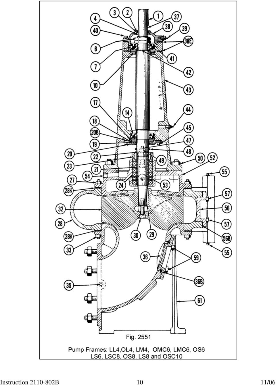
1 Service Instructions Manual B Chicago Pump type VOS and VPM non-clog pumps Frames: LL4, OL4, LM4, OM4, OMC6, LMC6, OS6, LS6, LSC8, OS8, LS8, OSC10, OLC10, LLC10 and OLC12 UPON RECEIPT OF PUMP EQUIPMENT: Check carefully to see that all equipment has been received and is in good condition. If parts are missing, report details immediately to Chicago Pump. If pump is damaged in shipment, note extent of damage on the freight bill and bill of lading and inform the Transportation Company. Do not leave the unit exposed to construction or weather hazards where pump, may be mechanically damaged or motor and ball bearings become wet. This pump is well designed, skillfully built, and rugged, but must be given the same careful attention that is accorded any precision machine. Chicago Pump Company 3905 Enterprise Ct Aurora, IL Ph: Fx: Figure 2544 Instruction B 1

2 INSTALLATION LOCATION: Both pump and motor should be located in a clean, dry place where it will be accessible for inspection or repair and protected against floods. A motor driven unit should be installed in a ventilated spot. A pump should be set as near the source of water supply as possible so that pipe connections are as short, simple, and direct as can be arranged. When units are large the need for head room or hoist facilities should also be considered. FOUNDATION: For permanence and quiet operation, it is important that a pump unit be firmly bolted to a substantial foundation. A properly engineered foundation should: 1. Be constructed of concrete with at least 6 cu. ft. per 100 lb. of pump unit. 2. Be at least 6 in. greater in length and width than the sub-base. 3. Be deep enough to bury the anchorage used. 4. Be "rooted" in a solid concrete floor by one of the following means: (a) When the concrete is newly poured, cast a shallow pit in the floor using a box form, or (b) leave reinforcement bars protrude above the floor level; (c) gouge out holes in an existing concrete floor. The recommended anchorage system is illustrated in Fig whereby anchor bolts are shouldered on loose fitting sleeves of pipe embedded in the concrete foundation. This arrangement permits bolt adjustment to conform accurately with sub-base holes after concrete is poured. Sleeves used should be approximately 2½ diameters larger than the bolts, and bolts should be long enough to permit the base to be raised 3/4 to 1 in. for grouting. The Figure illustrates one method for holding foundation bolts in position when pouring concrete into the form. The cross boards must be accurately drilled and spaced so that anchor bolts line up with the sub-base bolt holes. Plug top and bottom of the sleeves with oakum, as illustrated, before placing foundation bolts into the form. Make certain that sleeves are held rigidly against the square plates and that foundation bolts are accurately located to match sub-base holes before pouring the concrete. After concrete is poured and properly set, the cross boards are removed and the pump unit is ready to be mounted, leveled and grouted. Fig A recommended system of foundation Construction SETTING THE PUMP: Set pump on the foundation over the anchor bolts, but do not bolt down. Raise the pump unit 1" and level carefully for grouting by driving wedges under the pedestal. For leveling pump, place level on face of pump coupling half and face of pump discharge flange. GROUTING THE PUMP: After pump is raised and leveled pour a good quality grout under the pedestal and allow it to set; to prevent distortion, do not tighten down the nuts on the foundation bolts until the grout has properly hardened. Instruction B 2

3 PIPING: To obtain a well designed pipe system, note the following piping recommendations: 1. Make pipe connections to the pump so that there is no pipe strain upon the unit. Support the weight of piping on suitable concrete piers or on supporting pipes with flanged feet. 2. When running a pipe line through a concrete wall leave a generous, grooved, square hole and grout the pipe in only after pump unit is set and all final connections have been made. 3. Pipe lines should not be smaller in size than the connections on the pump, and where runs are long they should be at least a size or two larger. 4. In the suction pipe line include a gate valve near the pump, and employ flexible pipe connections (see Fig. 2089) for ease in making final connections and to prevent pipe strain due to settling of concrete. 5. On the discharge line include a suitable swing check valve and a gate valve near the pump. Note it is common practice, where space does not permit, to mount swing check valve in a vertical position. 6. Provide for drainage of the dry basin by means of an automatic sump pump. 7. The water seal connection (25) on the pump packing should be connected to a clear water supply having a pressure approximately 3 to 5 pounds greater than the discharge pressure of the pump. It should be noted that, as a precaution against contamination, health boards do not permit connecting the water seal line of a sewage pump directly to the city supply. A small water seal pumping unit is commonly used to meet health department requirements and at the same time provide positive seal pressure on the pump packing. Economical consumption of water may be obtained by installing a solenoid valve between the discharge of the seal water pump and the seal water connection at the sewage pump. The solenoid valve should be wired to the circuit of the sewage pump so that it will open when the sewage pump operates. When clear water for sealing is not available, a grease seal (Fig. 2893) may be substituted (see paragraph on lubrication). 8. Install a drain pipe from the connection at packing box drip pocket to the sump. To be readily cleanable; include a union in the line near the pump. Instruction B 3

4 TYPE VOS PUMPS: To install Universal Joint Shafting: (See Fig. 2544, page 1). When installing universal joint shafting, always place the "A" section (with the slip spline) at the bottom, with spline next to the pump. When more than one section is provided, the order of connection is evident from the connection fittings provided and from the installation drawing; the opposite shafting ends are fixed to the pump and motor shafts by means of keyed couplings held with set screws. Connect the shaft sections and align them approximately, fixing the shafting temporarily but firmly to the bearing support beams by clamping the intermediate guide or steady bearings to the beams with a sufficient number of "C" clamps. Caution! One side of the intermediate bearing housing has a drilled drainage hole. Be sure when installing that bearing is installed properly to provide drainage of top side of bearing. When all sections are joined, align each section separately with a level as accurately as possible, starting from the bottom and using metal shims behind the steady bearings where necessary. Although universal joints will compensate for considerable misalignment, for maximum efficiency it is desirable to obtain as exact alignment as possible. (See Fig. 1 and Fig. 2 for proper method of installation.) In making final adjustments, the slip spline should be spaced as near as possible to the mid-point of its slip or end play. Steady bearing are of the self-aligning type, perfect leveling of the bearings is not necessary; and since steady bearings are not provided to stand end-thrust, the shafting weight should be taken by the motor bearings. When alignment is completed, drill holes in. the bearing supports and bolt bearings in place. Remove "C" clamps. SETTING AND ALIGNING THE MOTOR ASSEMBLY: (See Fig. 2544). The motor is mounted on a tripod. Set the tripod over the floor hole; position the universal shafting to the motor coupling, setting the motor assembly so that it is level and the shafting alignment below is maintained. IMPORTANT: The motor must support the weight of the line shafting. The motor coupling half is in a fixed position to carry the weight of the line shaft (see Fig. 2544, page 1). You will note that the coupling half has been provided with two set screws located 90 0 apart. One set screw is directly over the keyway and locks the key in place. The other set screw has been located to line up with a drilled or spotted point on the motor shaft. This set screw MUST seat itself firmly into the cavity provided. CONTROLS: Different types of motors may be used depending upon size or service of the pump and the electrical currents available at the pump location. Since motors may be direct current or single-phase or three-phase alternating current, they may vary considerably according to the system of winding employed, and are specific as to current requirements; a discussion of controls covering all types would be lengthy and is therefore not attempted. In general, always provide a fused or circuit breaker protected disconnect switch in the motor circuit. In addition, a particular system of controls must be used, according to motor characteristics and application, which will satisfy the following requirements: 1. Provide adequate protection against such exigencies as high inrush starting current, low voltage, release and overload protection. 2. Complies with local electrical code requirements and local power company regulations. 3. Is adapted to the make of motor and application of the PUMP. 4. Is safe and convenient for operation or for shutting down to repair pump or motor. 5. Employ high quality equipment with sufficiently high ratings for any reasonable emergency. WIRING: Connect the electric service to the controls and make inter-control electrical connections according to wiring instructions accompanying the switches and motor, using conduit and wire sizes as required by local power companies. Be sure current characteristics of voltage and frequency indicated on the motor nameplate are the same as service provided. ROTATION: Check rotation of the motor; see that it turns in the direction indicated by the rotation arrow on pump casing (28) ; if incorrect refer to motor manufacturer's instructions for reversing. AUTOMATIC FLOAT CONTROL REGULATION: To maintain prime, the float control mechanism should be so regulated that the water level in the wet basin never falls below the level of the top of the pump discharge casing (28). When regulating the high water limit, submergence of the drainage inlet should be avoided. MECHANICAL ALTERNATOR: When a mechanical alternator is used, refer to Fig. 4, for proper installation and setting. Instruction B 4

5 FUSE RECOMMENDATIONS: Be certain fuses are installed and comply in size with the National Electric Code and Local Code recommendations. In general, fuses are sized approximately 200% of the motor ampere rating shown on the motor nameplate; however, fuse size may vary from 150% to 300%, depending on the type of motor. Figure 4 Installation of Mechanical Alternator LUBRICATION MOTOR LUBRICATION: Lubricate the motor according to motor manufacturer's instructions, avoiding over lubrication. PUMP LUBRICATION: 1. Ball Bearings-The pump has two sets of ball bearings lubricated separately through Alemite fittings located on the pump housing. In general pump bearings should be lubricated every six months. Avoid over lubrication. Use a high grade grease equal in consistency to the following: Citgo Lithium EP Grease Seals-See Fig When a grease seal is substituted for a water seal it is very important that grease pressure be constantly maintained on the packing. When a spring loaded grease cup is used for this purpose the cup must be kept loaded at all times with Grease. It is imperative that grease be forced through the packing at a rate of about 1 oz. per day. Instruction B 5

6 TYPE VOS PUMPS: Steady or Intermediate Guide Bearings : See Fig Steady bearings are provided with Alemite fittings for grease lubrication and should be lubricated with grease having the same consistency as the lubricant recommended for the pump. Steady bearings ordinarily need greasing only once every six months. Universal Joint Couplings: See Fig Universal joint bearings and slip splines are provided with Alemite fittings for grease lubrication, and may be lubricated with the same grease recommended for steady bearings. They need greasing only rarely, once a year usually being sufficient. Caution: Pull motor disconnect before lubricating. OPERATION CHECK THE FOLLOWING ITEMS BEFORE STARTING UNIT: 1. Be sure all equipment has been lubricated as per lubrication instructions. 2. Turn the shaft by hand to see that it rotates freely. If it sticks or turns with difficulty refer to the "Repairs" section of these instructions. 3. Verify that current characteristics of voltage and frequency on motor nameplate coincide with the service provided. 4. Verify that all thermal units are closed and the HOA switch (when used) is on "off" position. 5. Verify that gate valves on the suction and discharge lines are open. STARTING: To start the pump throw in the motor disconnect switch. The pump will not operate unless the float switch is closed. If a selector switch is used the pump may be run independent of float control by turning it to "on" or manual position. AFTER STARTING THE UNIT: 1. See that shaft rotates in the direction indicated by the rotation arrow on the pump casing and that pump is delivering water. 2. See that all pipe connections are tight and the check valves functioning. 3. Note operation of automatic control mechanism, observing a complete start-stop cycle; see that the liquid level control starts and stops pump properly as wet basin fills and is emptied by the pump. Check high-low water level adjustment 4. Observe the open line shafting, check for vibrating or "whipping". 5. See that there is the desired water leakage from stuffing box (refer to paragraph "4", under "Maintenance" for details). 6. See that bearings (7 and 14) do not overheat due either to over or under lubrication. 7. Observe operation of pump closely for the first day and at regular intervals for two weeks. A new machine is frequently stiff or initial control regulation may be incorrect; therefore the unit should be watched to note performance. (See "Periodic inspection".) MAINTENANCE: 1. Lubrication-At regular intervals lubricate motor, pump, steady bearings and universal shaft joints as per lubrication instructions. 2. Grease Seal-To be effective grease seals must maintain constant and sufficient grease pressure upon the packing. (See paragraph "2" under "Pump Lubrication".) 3. General Cleanliness-Keep the interior and exterior of motor and controls free from moisture, oil and dirt. When necessary blow out their interiors using a bellows. When switch contacts show signs of wear or pitting they should be replaced. 4. Stuffing box-occasionally observe the packing glands (23) for leakage. A slight leakage of seal water, say 20 drops per minute (large pumps may require more) from the stuffing box when pump is running acts as a lubricant and also keeps packing (24) cool and in good condition. If serious leakage is noted tighten the two gland nuts (49) evenly a few turns only; do not draw glands too tight. After adjusting packing glands turn the shaft by hand to be sure it rotates freely. If serious leakage will not stop, refer to "Repairs" instructions for packing renewal. Instruction B 6

7 PERIODIC INSPECTION: To insure the best operation of the pump make a systematic inspection at least once a week: 1. See that automatic float control responds to rising water level in the basin. 2. See that unit starts when the float switch makes contact and that pump shuts off at the low water level. 3. See that motor comes quickly up to speed and maintains constant rotation rate. LOCATING TROUBLE IF PUMP FAILS TO OPERATE: 1. Check fuses, circuit-breakers, and thermal units, see if blown, tripped or loose. Before replacing a burnt fuse be sure cause for blowing is determined and corrected. Before resetting a tripped thermal unit allow it to cool. 2. Be sure the shaft rotates, try turning by hand. If it is stuck or unusually stiff see that pump is not clogged; that motor, pump or steady bearings are not worn, dry or jammed by corrosion; that the shaft is properly aligned; and that packing glands (23) are not too tightly or unevenly adjusted. 3. See that switch contacts are not corroded, shorted or terminal connections broken anywhere in the circuit. 4. See if the automatic liquid level control mechanism is - functioning. 5. See if motor is shorted or burnt, or if brushes (when present) are stuck or worn. 6. See that wiring hook-up and service provided are correct and that all switches are set for operation. IF NO WATER IS DELIVERED: 1. See if the water level is so low that pump is not primed. 2. Check pump to see if it is air bound by venting casing at plug (26). 3. Check whether the suction pipe or inlet is clogged or gate valve closed. 4. See whether the gate valve in discharge line is shut or check valve is jammed. 5. Check discharge head, see if beyond pump rating. 6. See if pump rotation is reversed. 7. See if the impeller is badly worn. 8. See if the motor speed is too slow. 9. Determine if check valve is checking in the proper direction. IF NOT ENOUGH WATER IS DELIVERED: 1. See if there are air leaks in the suction line or stuffing box. 2. See if motor speed is too slow.. 3. See if the discharge head is higher than anticipated. 4. See if the impeller is worn or plugged up. IF FUSES BLOW OUT: 1. Check fuse rating used to that advised under "Fuse Recommendations". 2. Turn shaft by hand to see that it rotates freely. If it sticks or turns with difficulty see paragraph "2" under LOCATING TROUBLE. 3. Check wiring and controls. Test for loose connections. 4. See that controls are not worn or arcing. 5. See that motor is not grounded or partially burnt out. 6. Observe if motor is overheating from overload or lack of proper ventilation. 7. See if fuse location is in hot ambient condition. Fig 2089 Instruction B 7

8 REPAIRS IF PUMP REQUIRES CLEANING: Handholes are provided both in the volute of the discharge casing (28) and in the suction pedestal (61). By closing suction and discharge gate valves, draining the pump and removing the handhole cover cap screws (57 and 59), easy access to the pump interior is possible. TO DISMANTLE THE PUMP: 1. Open the electric circuit, close all gate valves on suction, discharge and water-seal lines. Drain the pump of water by removing the casing drain plug (58) or lower gauge connection plug (35). 2. Disconnect the bottom end of the lowest shaft section at a flange or yoke (See Fig and shafting instructions). The bottom or "A" section of universal joint shafting is easily swung aside to permit pump removal. Where more than one shaft section is used the remaining sections need not be disturbed. 3. Disconnect suction and discharge piping at the pump flange connections, break the water seal line at the nearest union, and disconnect similarly drip-pocket drain and dry basin drainage lines when used. 4. When extension grease lines are present, disconnect lines serving the pump. 5. Release pump pedestal anchor bolts. 6. The pump is now free and may be dismantled on the spot or hoisted from its location. 7. Remove the gland nuts (49), clamps (22), and glands (23). To remove glands on large type units the bolts and nuts holding gland halves together must first be removed. Pick out the rings of packing (24) and the water seal ring (53) noting carefully the number of packing rings used above and below the water seal ring. 8. Remove pedestal nuts (33A) separating suction pedestal (61) from the discharge casing (28). The pump is thus freed from its mount. 9. Hoist or lift pump off the pedestal, and lay it on its side. 10. Using an Allen wrench, remove the impeller hollow head set screw (31) when furnished, and holding the shaft at the coupling end, remove the impeller screw (30). 11. Remove the discharge casing (28). 12. Remove the pump coupling (retain coupling key-1), and releasing screws (40) remove the bearing cap (38) and bearing cage (41-when present). 13. To remove the impeller (32) insert a long cap screw in place of the impeller screw (30), turn it in as far as it will go. Loosen bearing cap (38) by loosening the cap screws (40). This will allow the impeller to rest against the casing cover (52), also it will prevent chipping the ball bearing (7). Tap on the screw with a hammer to jar the impeller loose. Remove cap screw and slip off the impeller. Retain the impeller key (29). 14. Release casing nuts (27), also bearing cap screws (50), when present. Remove casing cover (52) and bearing housing (43). Retain the water seal ring (53) and deflector ring (48) 15. Unscrew the shaft nuts (6) and pull off the upper bearing (7). Retain the spacer shims (42) under it. 16. Unscrew cap screws (45) and remove the lower bearing retaining plate (20), when present, allowing it to drop down. 17. Pull the shaft (37) out of the bearing housing from the bottom end. 18. If necessary the lower bearing (14) may be removed, but be sure to mark its exact location on the shaft. 19. Clean all parts with kerosene before replacing. TO ASSEMBLE THE PUMP: To rebuild the pump reverse the above procedure, but observe the following precautions: 1. File off all burrs made on machined surfaces. 2. Grease all paper gaskets and use only.012 inch Manila paper. Gaskets are used at the following points: (a) Under bearing cap (38)-paper. (b) Between bearing cage (41-when present) and bearing housing (43)-paper. (c) Between casing cover (52) and discharge casing (28)-paper. (d) Between discharge casing (28) and suction pedestal (61)-paper. (e) Under handhole covers rubber. 3. When felt washers (2, 10, 12, or 19) or grease seals (5 or 16) show signs of wear, replace them. 4. Be sure to set on the lower bearing retaining plate (20, when used), water seal ring (53), and deflector ring (48) before mounting the casing cover (52). 5. Replace spacer shims (42) under the upper bearing (7). The proper clearance between impeller and casing suction face (below it), when impellers are open type, is.010" to.020"; when impellers are closed type the recommended bottom (butt) clearance is.005" to.010". Clearance adjustment is made by varying the shimming (42) under the upper ball bearing (7) ; increasing shim thickness reduces clearance. Instruction B 8
.")
9 6. When wearing rings are used the proper clearance between them is.011". 7. Replace the packing (24). Use only the proper size soft, square, woven asbestos, graphite impregnated packing cut into individual rings; dip them in oil before inserting. Be sure the water seal and packing rings are replaced in the order they were originally found so that the water seal ring (53) is aligned with the water or grease seal inlet (25). The spliced ends of the packing rings should be staggered to insure a perfect seal. ORDERING PARTS: When ordering supplies always furnish pump number indicated on nameplate attached to the pump. State quantity, item number, name or description of part. PARTS LIST 1. Coupling key 27A. Casing nut 50A. Bearing housing stud 2. Felt washer 27B. Casing stud 50B. Bearing housing nut 3. Felt washer retaining plate 28. Discharge casing 52. Casing cover 4. Retaining wire 28K. Discharge casing gasket Grease seal 29. Impeller key 54. Water seal ring Drip pocket drain (plug) 6. Shaft nut 30. Impeller screw 55. Discharge gauge connection (plug) 7. Upper ball bearing 31. Impeller set screw (when furnished) 56. Discharge handhole cover 10. Grease seal 32. Impeller 56B. Handhole cover gasket 11. Top washer plate 33A. Pedestal nut 57. Handhole cover cap screw 12. Felt washer 33B. Pedestal stud 58. Discharge casing drain (plug) 13. Bottom washer plate 35. Suction gauge connection (plug) 59. Suction cover cap screw 14. Lower ball bearing 36. Suction handhole cover 61. Suction pedestal 15. Bearing collar set screw 37. Shaft 62. Grease line (not shown) Impeller wear ring (not 16. Grease seal 38. Bearing cap 66. shown) Pedestal wearing ring (not 17. Retaining wire 38E. Bearing cap gasket 67. shown) 18. Retaining plate 39. Upper grease fitting 68 Motor half coupling 19. Felt washer 40. Bearing cap screw 69 Coupling set screw 20. Bearing retaining plate 40C. Lock washer 70 Coupling sleeve 20B. Bearing retaining plate gasket 41. Bearing cage 71 Pump half coupling 21. Shaft sleeve 42. Spacer shims 72 Motor pedestal 22. Packing gland clamp 43. Bearing housing 73 Motor adapter ring 23. Packing gland 44. Lower grease fitting 24. Packing 45. Retaining plate cap screw 25. Water seal connection (plug) 47. Packing gland bolt 26. Vent plug 48. Deflector ring 49. Packing gland nut Instruction B 9

10 Instruction B 10
11 Instruction B 11

12 GASKET IDENTIFICATION A. Bearing cap gasket B. Bearing cage gasket C. Discharge casing gasket D. Suction handhole cover gasket E. Discharge casing handhole gasket F. Suction studs G. Suction stud nut H. Retaining plate gasket Type VPM (Vertical Pedestal-Mounted) Pumps GENERAL DIRECTIONS: Vertical pedestal non-clog pumps have the same general design as do vertical open-shaft pumps, with the exception that they employ machined pedestals to support the motors and are connected to meters through flexible couplings. The preceding general facts concerning vertical open shaft pumps therefore apply as well to these units. PARTS LIST: Figures 2547 and 2551 with related parts list for open-shaft pumps en pages seven and eight apply equally to pedestal mounted pumps. Additional items are listed below. FLOODING: When pedestal-mounted pumps are installed in basins, suitable means for manual, or preferably automatic, drainage should be provided. MOUNTING THE MOTOR AND SETTING THE COUPLING: Motors are normally shipped unmounted to prevent damage in transit. The meter coupling, if net installed at the factory, should be temporarily installed en the motor shaft. This coupling must be drilled and tapped at two locations, 90 apart, with one set screw hole at the shaft key. At the ether location, an indentation or flat must be made in the meter shaft to assure proper seating of the set screw. Place the coupling disc en the pump half coupling. The meter and meter pedestal or adapter ring are provided with self-aligning tongue-and-groove surfaces. Clean both surfaces before mounting the meter, and check that the meter face fits snugly en the pedestal, then fasten the motor belts. Adjust the coupling to allow metal to metal clearance of about 3'1g " to 1/8". Coupling sleeves should net be pressed too tightly between the coupling faces. If insufficient clearances are provided, the couplings may strike causing noise. Tighten the meter coupling set screws. Two set screws at each location, one en top of each ether, should be used. Instruction B 12

STORAGE, INSTALLATION AND MAINTENANCE PROCEDURES
 GATE VALVE O.S. & Y 1.0 Periodic Inspections 1.1 The valve stem packing should be inspected at least monthly. If the stem packing shows signs of leakage, simply tighten the adjusting nuts to compress the
OPERATION & MAINTENANCE MANUAL. for VERTICAL INLINE PUMPS
 OPERATION & MAINTENANCE MANUAL for VERTICAL INLINE PUMPS PATTERSON PUMP COMPANY A SUBSIDIARY OF THE GORMAN-RUPP COMPANY PO Box 790 9201 Ayersville Road Toccoa, Georgia 30577 Telephone: 706-886-2101 SAFETY
INSTALLATION & OPERATING INSTRUCTIONS
 INSTALLATION & OPERATING INSTRUCTIONS WARNING RISK OF ELECTRIC SHOCK. CONNECT ONLY TO A CIRCUIT PROTECTED BY A GROUND-FAULT CIRCUIT-INTERRUPTER. THE UNIT SHOULD BE INSTALLED BY A QUALIFIED SERVICE REPRESENTATIVE.
BOWIE PUMPS OPERATION - MAINTENANCE
 BOWIE PUMPS OPERATION - MAINTENANCE PUMPING PRINCIPLE: The meshing owieeof the gears cause a slight depression, with the resulting enmeshing of the gears causing a vacuum drawing the fluid being pumped
Wilo SP Series Submersible Sump Pumps ECS. ECS19-15.25 ECS22-15.33 ECS24-15.50 Installation and operating instructions
 Wilo SP Series Submersible Sump Pumps ECS ECS19-15.25 ECS22-15.33 ECS24-15.50 Installation and operating instructions PREINSTALLATION CHECK Inspect this pump before it is used. Occasionally, pumps can
Trouble Shooting. Pump
 Trouble Shooting Pump Trouble Possible Cause Remedy Oil leaking in the area of water pump crankshaft Worn crankshaft seal, bad bearing, grooved shaft, or failure of retainer o-ring. Excessive play on crankshaft
Constantemp Double Wall Low pressure steam-water Heater F-340LDW,F-640LDW, F-940LDW and F-1240LDW
 Installation, Operating and Maintenance Instructions 90/4.5.5 Rev. 0 Constantemp Double Wall Low pressure steam-water Heater F-340LDW,F-640LDW, F-940LDW and F-1240LDW Table of Contents SECTION I... 2 INSTALLATION...
MODEL 300505 INSTALLATION INSTRUCTIONS
 WWW.BURCAM.COM 2190 Boul. Dagenais West TEL: 514.337.4415 LAVAL (QUEBEC) FAX: 514.337.4029 CANADA H7L 5X9 info@burcam.com Your pump has been carefully packaged at the factory to prevent damage during shipping.
Owner s Manual. Models: 2S5P & 3S5P OPERATION AND MAINTENANCE OF SELF-PRIMING CENTRIFUGAL TRASH PUMPS PEDESTAL DRIVE
 Owner s Manual Models: 2S5P & 3S5P OPERATION AND MAINTENANCE OF SELF-PRIMING CENTRIFUGAL TRASH PUMPS PEDESTAL DRIVE WARNING!! Installation & Operating Instructions Self-Priming Centrifugal Pump DO NOT
SEWER CHEWER Wastewater / Sludge Grinder Submersible Gearmotor
 INSTALLATION, OPERATION AND MAINTENANCE MANUAL For SEWER CHEWER Wastewater / Sludge Grinder Submersible Gearmotor Yeomans Chicago Corporation 3905 Enterprise Court P.O. Box 6620 Aurora, IL 60598-0620 Phone:
Char-Lynn Hydraulic Motor. Repair Information. 10 000 Series. October, 1997
 Char-Lynn Hydraulic Motor October, 1997 Repair Information Geroler Motor Two Speed 001 27 Retainer inside bore of valve plate bearingless motors only 4 15 16 3 6 35 Parts Drawing 25 2 2 1 19 17 36 40 47
2100 AD 015 0009 Mirror Elevator Ball Nut Replacement Procedure
 2100 AD 015 0009 Mirror Elevator Ball Nut Replacement Procedure Derek Guenther 1/28/2015 Rev. Purpose The purpose of this document is to describe the procedure necessary to replace one of the ball nuts
WE-350 Series ¼ Turn Electric Actuator
 WE-350 Series ¼ Turn Electric Actuator Operation and Installation Manual Pg 1 (Rev. 020113) Table of Contents 1.0 General 1.1 Pre-Installation Inspection 1.2 Storage 1.3 Features & General Information
Oil and Coolant Circulating Heating System. Model - OCSM
 Oil and Coolant Circulating Heating System Model - OCSM Installation & Operation Manual 216280-000 REV 2 Identifying Your System The HOTSTART heating system is designed to heat fluids for use in marine
300 SERIES 331, 332, 333, 344, 356 AND 367 MODELS
 Section: MOYNO 500 PUMPS Page: 1 of 8 Date: March 1, 1998 SERVICE MANUAL MOYNO 500 PUMPS 300 SERIES 331, 332, 333, 344, 356 AND 367 MODELS Mechanical Seal Models Packing Gland Models MODELS DESIGN FEATURES
ALIGNMENT. Pump and Driver Alignment
 ALIGNMENT Pump and Driver Alignment Alignment Subject: Pump and Driver Alignment In the pump business alignment means that the centerline of the pump is aligned with the centerline of the driver. Although
BICO CHIPMUNK JAW CRUSHER - TYPE WD
 BICO CHIPMUNK JAW CRUSHER - TYPE WD The Bico Chipmunk Jaw Crusher is designed to give long and efficient service. In order to secure the long life and excellent performance that your crusher is capable
GT Horizontal Split Casing Pumps
 GT Horizontal Split Casing Pumps 302-054 Operations and Maintenance Manual SUPERSEDES: New EFFECTIVE: March 1, 2009 Plant ID No. 001-3930 SAFETY REQUIREMENTS These operating instructions must be complied
Table V. Troubleshooting Checklist for Refrigeration Systems. Air or non-condensable gas in system. Inlet water warm.
 Table V Troubleshooting Checklist for Refrigeration Systems TROUBLE POSSIBLE CAUSE CORRECTIVE MEASURE High condensing pressure. Low condensing pressure. Air or non-condensable gas in system. Inlet water
Volkswagen Jetta, Golf, GTI 1999, 2000 2.8 Liter VR6 2V Engine Mechanical, Engine Code(s): AFP 17 Engine-Lubrication (Page GR-17)
: AFP 17 Engine-Lubrication (Page GR-17)") 17 Engine-Lubrication (Page GR-17) Lubrication system components, removing and installing Oil filter housing, disassembling and assembling Oil pan, removing and installing Oil pressure and oil pressure
17 Engine-Lubrication (Page GR-17) Lubrication system components, removing and installing Oil filter housing, disassembling and assembling Oil pan, removing and installing Oil pressure and oil pressure
A.Y. McDonald Mfg. Co. Troubleshooting Submersible and Jet Pumps
 A.Y. McDonald Mfg. Co. Troubleshooting Submersible and Jet Pumps Troubleshooting Submersible Pumps Fuse overload or circuit breaker trips when motor is started 1. Incorrect line voltage. Check the line
KESSEL KTP 500 Submersible Pump with lateral and vertical outlet connection Order Numbers 28710, 28810, 28850
 INSTALLATION AND OPERATING INSTRUCTIONS KESSEL KTP 500 Submersible Pump with lateral and vertical outlet connection Order Numbers 28710, 28810, 28850 Product advantages Automatic float switch as water
OPERATION & MAINTENANCE MANUAL. for 5 X 3 MAC - 5 X 4 MAC DOUBLE SUCTION SPLIT CASE PUMPS
 OPERATION & MAINTENANCE MANUAL for 5 X 3 MAC - 5 X 4 MAC DOUBLE SUCTION SPLIT CASE PUMPS PATTERSON PUMP COMPANY A SUBSIDIARY OF THE GORMAN-RUPP COMPANY PO Box 790 9201 Ayersville Road Toccoa, Georgia 30577
Drive shaft, servicing
 Volkswagen Passat B6 - Drive shaft, servicing Стр. 1 из 41 40-7 Drive shaft, servicing Drive shafts, overview I - Assembly overview: Drive axle with CV joint VL100 40-7, Drive axle with CV joint VL100,
This instruction is valid for all ACD pump models shown on page 2
 Screw pumps ACD Maintenance and Service Instruction This instruction is valid for all ACD pump models shown on page 2 Contents Page List of components 2 Exploded view/ordering code 3 Service intervals
Packaged Terminal Air Conditioner Wall Sleeve Installation
 Installation & Maintenance Data IM 1196 Group: PTAC Part Number: 910141799 Date: October 2013 Packaged Terminal Air Conditioner Installation x 42" PGAN with Top-Mounted Hydronic Heat Note: Installation
OPERATIONS AND MAINTENANCE INFORMATION FOR: THE CANPLAS BACKWATER VALVE THE CHEMTROL BALL SHUT OFF VALVE SUMP PUMPS AND WASTEWATER EJECTOR PUMPS
 OPERATIONS AND MAINTENANCE INFORMATION FOR: THE CANPLAS BACKWATER VALVE THE CHEMTROL BALL SHUT OFF VALVE SUMP PUMPS AND WASTEWATER EJECTOR PUMPS THE LOUISVILLE AND JEFFERSON COUNTY METROPOLITAN SEWER DISTRICT
1.8 CRANKSHAFT OIL SEALS
 SERIES 60 SERVICE MANUAL 1.8 CRANKSHAFT OIL SEALS An oil seal is fitted between each end of the crankshaft and the bores of the flywheel housing and gear case cover to retain the lubricating oil in the
S33 Sump Pump INSTRUCTIONS AND SERVICE MANUAL VERTICAL FLOAT SWITCH S33V1 & S33V1C AUTOMATIC S33P1 & S33PC-1 (CONTROL WITH SERIES PLUG) NOT SHOWN
 NOT SHOWN") S33 Sump Pump INSTRUCTIONS AND SERVICE MANUAL VERTICAL FLOAT SWITCH S33V1 & S33V1C AUTOMATIC S33P1 & S33PC-1 (CONTROL WITH SERIES PLUG) NOT SHOWN AUTOMATIC S33A1 & S33A1C R WARNING risk of electric shock.
S33 Sump Pump INSTRUCTIONS AND SERVICE MANUAL VERTICAL FLOAT SWITCH S33V1 & S33V1C AUTOMATIC S33P1 & S33PC-1 (CONTROL WITH SERIES PLUG) NOT SHOWN AUTOMATIC S33A1 & S33A1C R WARNING risk of electric shock.
INSTRUCTIONS AND PARTS LIST FOR MODEL 70H & 75H HAND-OPERATED HYDRAULIC PRESS
 INSTRUCTIONS AND PARTS LIST FOR MODEL 70H & 75H HAND-OPERATED HYDRAULIC PRESS SETTING UP THE PRESS FOR OPERATION For shipping convenience, the gauge, pump handle, hoist crank, screw nose and base angles
Fire Hydrant Troubleshooting
 Fire Hydrant Troubleshooting Pulsation or chatter during opening and flow of water from hydrant. Loose condition in stem at lower valve plate nut. Tighten lower valve plate nut and secure with SS lock
DiscPlus DX195 and DX225 Air Disc Brakes
 Revised 11-04 Technical Bulletin Revised 1 Technical 11-04 Bulletin DiscPlus DX195 and DX225 Air Disc Brakes Inspection, Installation and Diagnostics Air Disc Brake Inspection Intervals and Procedures
Tri-Homo Style Operation and Maintenance Instructions
 Tri-Homo Style Operation and Maintenance Instructions One Research Drive Stratford, CT 06615 (203) 375-0063 www.sonicmixing.com 1 Installation and Start-up Do not perform following adjustments without
Trash Pumps Models: 56200, 562000, 56201, 562001, 56300, 563000, 56301, 563001
 Trash Pumps Models: 56200, 562000, 56201, 562001, 56300, 563000, 56301, 563001 Specifically designed pumps for heavy duty applications Handles solids with eas and simple to open and clean Standard roll
CORNELL PUMPS IRRIGATION FOOD MUNICIPAL PROCESS INDUSTRIAL
 EFFICIENT BY DESIGN Installation & Care of PUMPS IRRIGATION FOOD MUNICIPAL PROCESS INDUSTRIAL Cornell Pump Company P.O. Box 6334 Portland, Oregon 97228 Phone: (503) 653-0330 Fax: (503) 653-0338 Web: www.cornellpump.com
Table of Contents. Overview 1. Pump Disassembly 2. Control Disassembly / Reassembly 7. Pump Reassembly 13. Adjustment Procedures DR Control 19
 Table of Contents Overview 1 Pump Disassembly 2 Control Disassembly / Reassembly 7 Pump Reassembly 13 Adjustment Procedures DR Control 19 Adjustment Procedures DRG Control 20 Adjustment Procedures DFR
OPERATION AND MAINTENANCE MANUAL 5-1/4 B-84-B-5 FIRE HYDRANT
 OPERATION AND MAINTENANCE MANUAL 5-1/4 B-84-B-5 FIRE HYDRANT INDEX AMERICAN - DARLING 5-1/4 IN. B-84-B-5 FIRE HYDRANT OPERATION AND MAINTENANCE MANUAL OPERATION AND MAINTENANCE REPAIRS Operation and Maintenance...
Installation, Operating and Maintenance Instructions for AEON Metal Seated Gate Valve (MSGV) Water
 Water") 1 Foreword 1.1 Thank you for choosing one of the range of AEON's BS standard valves. For safety purposes, the user shall read this instruction to fully understand the operation of the product. 2 AEON Design
1 Foreword 1.1 Thank you for choosing one of the range of AEON's BS standard valves. For safety purposes, the user shall read this instruction to fully understand the operation of the product. 2 AEON Design
AWWA Butterfly Valve Operation and Maintenance Manual Series 511A & 510A 20 and Smaller
 January 2013 AWWA Butterfly Valve Operation and Maintenance Manual Series 511A & 510A 20 and Smaller Milliken Valve Company 190 Brodhead Avenue, Suite 100 Bethlehem, PA 18017 Phone: (610) 861-8803 Fax:
Pump Maintenance - Repair
 Pump Maintenance - Repair Brian Trombly Mo Droppers Cummins Bridgeway, Gaylord, Mi The basic centrifugal pump consists of two main elements: 1. The rotating element which includes an impeller and a shaft.
Hydraulics Trouble Shooting Guide. TS-Guide_R.doc
 Hydraulics Trouble Shooting Guide TS-Guide_R.doc Table of Contents Condensed Table... 1 Valves... 3 Cylinders... 3 Boosters... 4 Fluid Motors... 5 Vane Pumps... 6 Radial Piston Pumps... 9 Hydraulic Systems...
SINGLE PHASE MOTORS. INSTALLATION AND MAINTENANCE MANUAL March 21, 2006
 SINGLE PHASE MOTORS INSTALLATION AND MAINTENANCE MANUAL March 21, 2006 Irvine, California (800) 474-0520 Indianapolis, Indiana (800) 866-7973 Hamilton, Ontario (800) 809-0330 e-mail: sales@sterlingelectric.com
Fuel Injection Pump, Rotary (005-014)
") Fuel Injection Pump, Rotary View Related Topic Page 1 of 30 Fuel Injection Pump, Rotary (005-014) Table of Contents Summary General Information Preparatory Steps Remove Front Gear Train Rear Gear Train
Fuel Injection Pump, Rotary View Related Topic Page 1 of 30 Fuel Injection Pump, Rotary (005-014) Table of Contents Summary General Information Preparatory Steps Remove Front Gear Train Rear Gear Train
Volkswagen New Beetle 2.0 Liter 4-cyl General, Engine (Engine Code AEG) 17 Engine-Lubrication system (Page GR-17)
 17 Engine-Lubrication system (Page GR-17)") 17 Engine-Lubrication system (Page GR-17) Lubrication system components, removing and installing Oil pan, removing and installing Oil pressure and oil pressure switch, checking Dynamic oil pressure warning
17 Engine-Lubrication system (Page GR-17) Lubrication system components, removing and installing Oil pan, removing and installing Oil pressure and oil pressure switch, checking Dynamic oil pressure warning
DeZURIK 3-20" BAW AWWA BUTTERFLY VALVES WITH TRANSFER MOLDED SEAT
 3-20" BAW AWWA BUTTERFLY VALVES WITH TRANSFER MOLDED SEAT Instruction D10386 August 2013 Instructions These instructions provide installation, operation and maintenance information for BAW Butterfly Valves.
Rebuild Instructions for 70001 and 70010 Transmission
 Rebuild Instructions for 70001 and 70010 Transmission Brinn, Incorporated 1615 Tech Drive Bay City, MI 48706 Telephone 989.686.8920 Fax 989.686.6520 www.brinninc.com Notice Read all instructions before
PLUMBING CARE AND REPAIR
 PLUMBING CARE AND REPAIR No special skills are required for any of the repairs described in this section. Plumbing repairs are seldom dangerous unless leaking water is soaking areas where there are electrical
Mueller B-101 and A-3 Drilling and Tapping Machines
 TM TM Mueller and Drilling and Tapping Machines A guide to selecting Mueller Equipment Mueller TM TM and Drilling and Tapping Machines When it comes to line stopping and drilling and tapping technology
Series 1510 and 1510/Universal Centrifugal Pumps
 Bell & Gossett INSTRUCTION MANUAL P81673 REVISION F Series 1510 and 1510/Universal Centrifugal Pumps Installation, Operation and Service Instructions INSTALLER: PLEASE LEAVE THIS MANUAL FOR THE OWNER S
LU6X-130 Instructions and Parts List (including LU6X Basic) Operating Instructions
 Operating Instructions") LORTONE LU6X-130 Item # 061-092 LU6X Basic Item # 061-090 LU6X-130 Instructions and Parts List (including LU6X Basic) Operating Instructions Introduction The LU6X is one the most versatile pieces of equipment
LORTONE LU6X-130 Item # 061-092 LU6X Basic Item # 061-090 LU6X-130 Instructions and Parts List (including LU6X Basic) Operating Instructions Introduction The LU6X is one the most versatile pieces of equipment
IMPORTANT SAFETY NOTICE
 IMPORTANT SAFETY NOTICE To: Our Valued Customers User safety is a major focus in the design of our products. Following the precautions outlined in this manual will minimize your risk of injury. ITT Goulds
Chapter 7 Hydraulic System Troubleshooting
 Chapter 7 Hydraulic System Troubleshooting General The following troubleshooting information is provided as a general guide to identify, locate and correct problems that may be experienced with the hydraulic
Float and Thermostatic Traps Series H, C and X
 Hoffman Specialty Installation & Maintenance Instructions HS-(E) and Thermostatic Traps Series H, C and X Series C & NPT Series C NPT Series X NPT Series C NPT Series H Ratings Maximum Max. Operating NPT
Vertical Turbine Pump with Suction Can Types VTP and VTM
 Vertical Turbine Pump with Suction Can Types VTP and VTM INSTRUCTIONS Installation Operation Maintenance Repair Read this entire bulletin before attempting to repair this pump. For installation and operation
Parts Replacement Manual For DODGE TORQUE-ARM Speed Reducers Straight Bore & Taper Bushed
 Parts Replacement Manual For TORQUE-ARM Speed Reducers Straight Bore & Taper Bushed TXT815A - TXT825A SIZES: TXT915A - TXT926A TXT1015A - TXT1024A WARNING: Because of the possible danger to person(s) or
SRA-125/SRAX-125 Double-Rail Lift-Out Rail System Installation & Service Manual with Parts List
 SRA-125/SRAX-125 Double-Rail Lift-Out Rail System Installation & Service Manual with Parts List For MG, WG, WGL, and Grinder Pumps for Effluent & Sewage CAUTION! Read these safety warnings first before
CDS TROUBLESHOOTING SECTION I. VACUUM. 1.0. Weak vacuum at wand. Gauge reads normal (10hg to 14hg)
") CDS TROUBLESHOOTING SECTION I. VACUUM 1.0. Weak vacuum at wand. Gauge reads normal (10hg to 14hg) 1.1. Clogged hoses or wand tube. Disconnect hoses and carefully check for an obstruction. 1.2. Excessive
CDS TROUBLESHOOTING SECTION I. VACUUM 1.0. Weak vacuum at wand. Gauge reads normal (10hg to 14hg) 1.1. Clogged hoses or wand tube. Disconnect hoses and carefully check for an obstruction. 1.2. Excessive
DANGER DANGER. General Information. Safety Is Your Responsibility. Ordering Parts. Contact Information
 Safety Safety Is Your Responsibility DANGER To avoid personal injury or death, carefully read and understand all instructions pertaining to the Anthony Liftgates product. Do not attempt to install, operate,
2" & 3" Poly Wet Seal Pump Instruction Manual
 Always place the pump as close to the liquid to be pumped as possible. Keep the suction line short and with few bends. Keep the pump and engine on a level foundation. A poor foundation and a heavy suction
1/3 HP Submersible Sump Pump with Vertical Float Switch
 1/3 HP Submersible Sump with Vertical Float Switch Item 68476 Specifications Float Switch Operation Height 7.1 IN. ON / 2.8 IN. OFF Electrical Requirements 120V~ / 60Hz / 7.6A Power Length Maximum Capacity
TABLE OF CONTENTS. I. TROUBLESHOOTING... 2 - Section 1.01: Common Problems/Solutions... 2
 BAL Accu-Slide System I. Table of Contents TABLE OF CONTENTS I. TROUBLESHOOTING... 2 - Section 1.01: Common Problems/Solutions... 2 II. GETTING STARTED... 5 - Section 2.01: Tools You Will Need... 5 - Section
3. SEISCO PARTS & SERVICE REMOVAL AND REPAIR GUIDE
 4 3. SEISCO PARTS & SERVICE REMOVAL AND REPAIR GUIDE A. Changing the Control Board B. Replacing a Heating Element C. Thermistor Replacement D. High Limit Switch Replacement E. Level Detector Replacement
VERTICAL AND HORIZONTAL END SUCTION PUMPS INSTALLATION, OPERATION AND MAINTENANCE MANUAL
 GUSHER PUMPS, INC. 115 INDUSTRIAL DRIVE WILLIAMSTOWN, KY 41097 PHONE: 859-824-3100 FAX: 859-824-7428 www.gusher.com VERTICAL AND HORIZONTAL END SUCTION PUMPS INSTALLATION, OPERATION AND MAINTENANCE MANUAL
OPERATING AND MAINTENANCE INSTRUCTIONS PUMP TYPE 215.10
 OPERATING AND MAINTENANCE INSTRUCTIONS PUMP TYPE 215.10 To Pump model Pump number Our order Your order Order date Reference Item number Destination Plant Before storing, installation, operation or maintenance
DO NOT attempt to repair hub and wheel bearing assembly.
 Page 1 of 6 HUB & WHEEL BEARINGS (WITH PULSE VACUUM HUBLOCK) DO NOT attempt to repair hub and wheel bearing assembly. Removal DO NOT remove hub lock assembly by prying on hub lock legs. This can crack
MAINTENANCE INSTRUCTIONS FOR THE CLEAN-FLO CONTINUOUS LAMINAR FLOW INVERSION / OXYGENATION SYSTEM
 MAINTENANCE INSTRUCTIONS FOR THE CLEAN-FLO CONTINUOUS LAMINAR FLOW INVERSION / OXYGENATION SYSTEM Maintenance is critical to the efficient performance of the CLEAN-FLO system. These maintenance activities
AC Electric Motors best practice
 If you want to learn more about best practice machinery maintenance, or world class mechanical equipment maintenance and installation practices, follow the link to our Online Store and see the Training
Dry Pit Solids Handling Pumps
 Dry Pit Solids Handling Pumps A Time-Tested Leader Chicago Pump Dry Pit Solids Handling Pumps have an established reputation of efficiency, long life and reliable operation First in: Quality 3Reliability
Installation and Operating Instructions Installation Instructions for SS EPE-316L Series
 INSTR3010 0406 Installation and Operating Instructions Installation Instructions for SS EPE-316L Series Congratulations on your purchase of this Aqua-Pure high flow, single housing filtration system. This
SunMaxx Solar Filling Station Operating Instructions
 SunMaxx Solar Filling Operating Instructions Content 1. Declaration of conformity... 2 2. Introduction... 2 3. Transportation and unpacking... 4 4. Mounting and commissioning... 5 5. End of operation...
Owners & Installation Manual for the Sheridan, Mountainair, Pine Valley and Old Forge Ceiling Fan Family
 Owners & Installation Manual for the Sheridan, Mountainair, Pine Valley and Old Forge Ceiling Fan Family Part of the Kiva Lighting Family Custom Lighting and Fans Since 1992 1312 12th St NW Albuquerque,
Owner s Manual Gantry Cranes
 Owner s Manual Gantry Cranes Fixed Height Gantry Crane MODEL NUMBER: SERIAL NUMBER: CAPACITY IN TONS: Telescoping Gantry Crane Bushman AvonTec 262-790-4200, 800338-7810, Fax 262-790-4200 www.bushmanavontec.com
Spicer Axles & Brakes ABIB-0302
 Information Bulletin Bulletin Type: Parts / Service Information Topic: Dana LMS Hub Assembly Procedure Steer and Drive Axles Spicer Axles & Brakes ABIB-0302 Note: Bulletin ABIB-0302 replaces the original
Pump Skid Fabrication for Magnetic Coupling. Rick Soltis Chief Mechanic City of Bedford
 Pump Skid Fabrication for Magnetic Coupling Rick Soltis Chief Mechanic City of Bedford Contents Magnetic Couplings What They Are, How They Work, Where They re Used Fabrication and Manufacturing of Pump
Model 362A AURORA. 340A/360A Series SINGLE STAGE END SUCTION PUMPS. www.aurorapump.com
 Model 62A MODEL 41A MODEL 44A AURORA 40A/60A Series SINGLE STAGE END PUMPS www.aurorapump.com SINGLE STAGE END PUMPS AURORA 40A/60A Series Single Stage End Suction Pumps Capacities to 4500 G.P.M. (1022
TYPE E Main Valve Sizes 3 /8 through 12
 SD 3001F PRINTED IN U.S.A. SD 3001F/0707 A B TYPE E MAIN VALVE C D E TYPE E Main Valve Sizes 3 /8 through 12 The Spence Type E Main Valve is of normally closed, single seat design featuring packless construction,
HYDRAULIC LIFT TABLE CART 2200-LB.
 HYDRAULIC LIFT TABLE CART 2200-LB. OWNER S MANUAL WARNING: Read carefully and understand all MACHINE ADJUSTMENT AND OPERATION INSTRUCTIONS before operating. Failure to follow the safety rules and other
OPERATING AND MAINTENANCE INSTRUCTIONS CLIMATE CONTROL/INDUSTRIAL
 OPERATING AND MAINTENANCE INSTRUCTIONS CLIMATE CONTROL/INDUSTRIAL PERFORMANCE UNDER PRESSURE 2362 Emerson Street Jacksonville, Florida 32207 (800) 394-5575 (904) 396-5575 A Message from the President Air
TECHNICAL SERVICE MANUAL
 TECHNICAL SERVICE MANUAL HEAVY-DUTY PUMPS SERIES 4195 AND 495 SIZES GG - AL SECTION TSM 144 PAGE 1 of 10 ISSUE D CONTENTS Introduction....................... 1 Safety Information.................... 2
Industrial Process Pump Safety Manual IMPORTANT SAFETY NOTICE
 Industrial Process Pump Safety Manual IMPORTANT SAFETY NOTICE To: Our Valued Customers User safety is a major focus in the design of our products. Following the precautions outlined in this manual will
AIR RELEASE, CLEANOUT, AND SEWER MANHOLES
 AIR RELEASE, CLEANOUT, AND SEWER MANHOLES **From Hartford IM BLDG(10) DESCRIPTION. This work shall consist of the construction of air release, cleanout, and sanitary sewer manholes; and the furnishing
INSTALLATION and OPERATION RANGE BALL CONVEYOR MODEL NO: BC-001AN
 Easy Picker Golf Products, Inc. 415 Leonard Blvd. N., Lehigh Acres, FL 33971 PH: 239-368-6600 FAX: 239-369-1579 Service: 800-982-4653 SALES: 800-641-4653 www.easypicker.com salesdept@easypicker.com INSTALLATION
KS Vertical In-Line Pump
 KS Vertical In-Line Pump 302-032 Installation, Operation & Maintenance Manual SUPERSEDES: July 1, 2010 EFFECTIVE: August 1, 2012 Plant ID No. 001-1014 SAFETY REQUIREMENTS 1. IMPORTANT! These instructions
PRODUCT MANUAL - M090
 PRODUCT MANUAL - M090 MODEL 203/266 ELECTRIC CAN OPENER 1 SAFETY CAUTION: SEVERED CAN LIDS HAVE CUTTING EDGES. USE OF A PROTECTIVE GLOVE OR TONGS IS ADVISED WHEN HANDLING LIDS. WARNING To avoid risk of
OPL BASIC. Dosing System for Professional Laundry machines. Contents
 OPL BASIC Dosing System for Professional Laundry machines Contents 1 Getting Started. Page 2 2 Installation. Page 4 3 Set Up & Operation. Page 8 4 Maintenance & Accessories. Page 10 5 Troubleshooting Page
Directions for use : Dosing chutes type DSX.
 Pag. 1-10 Directions for use : Dosing chutes type DSX. Introduction The linear vibrations of STILETTO consist of a drive part and a movable part which are connected to leave springs. The purpose of the
AXLE SHAFTS - FRONT. 1998 Pontiac Bonneville MODEL IDENTIFICATION DESCRIPTION & OPERATION TROUBLE SHOOTING REMOVAL & INSTALLATION
 AXLE SHAFTS - FRONT 1998 Pontiac Bonneville 1998-99 DRIVE AXLES FWD Axle Shafts - Cars - "C", "G" & "H" Bodies GM Aurora, Bonneville, Eighty Eight, LeSabre, LSS, Park Avenue, Regency, Riviera MODEL IDENTIFICATION
BRAKE DRUM AND ROTOR SERVICE INFORMATION
 SERVICE INFORMATION To achieve maximum drum life and optimum performance, proper brake maintenance and brake balance are essential. Consult your truck or trailer manufacturer s maintenance manual for proper
IF IT FLOWS THE BOWIE PUMP CAN PUMP IT
 IF IT FLOWS THE BOWIE PUMP CAN PUMP IT Bowie Industries, Inc. Bowie, TX 76230 USA Page 1 Bowie Pumps Manual General Pump Information..Page 2 300 Series Pumps.. Page 5 400 Series Pumps.Page 11 500 Series
The Ford Model A Water Pump
 The Ford Model A Water Pump George Washington Chapter, Inc. 3903 Old Lee Highway Fairfax, VA 22030 1 Table of Contents Introduction/Specifications.. 3 1. Water Pump Inspection and Removal. 4 a. Removal..
SERIES ASM NEOPRENE/EPMD FLANGED SINGLE SPHERE CONNECTOR CONNECTORS. Pressures to 225 PSIG (15.51 barg) Temperatures to 230ºF (110ºC)
 Temperatures to 230ºF (110ºC)") APPLICATIONS Process Industry Weak Acids Alkalies Compressed Air Pulp & Paper MODELS ASM - Flanged Connection OPTIONS Control Rods Oil & Gas Water & Waste Pump suction & discharge Sea water Chemical lines
APPLICATIONS Process Industry Weak Acids Alkalies Compressed Air Pulp & Paper MODELS ASM - Flanged Connection OPTIONS Control Rods Oil & Gas Water & Waste Pump suction & discharge Sea water Chemical lines
ELECTRIC MOTOR TEFC OPERATION & MAINTENANCE. meps Approved
 SOUTH AUSTRALIA HEAD OFFICE (Accounts / Payments) 34-36 Kinkaid Avenue NORTH PLYMPTON SA 5037 Ph: (08) 8295 5566 Fax: (08) 8295 5533 VICTORIA 23 James Street CLAYTON SOUTH VIC 3169 Ph: (03) 9544 2324 Fax:
ATS Overhead Table Shelf System INSTRUCTION MANUAL
 ATS Overhead Table Shelf System INSTRUCTION MANUAL ATS Overhead Table Shelf System Instruction Manual Warranty Newport Corporation warrants this product to be free of defects in material and workmanship
TWO-STAGE CENTRIFUGAL PUMPS
 MODELS I2C and I2CI/2C95 TWO-STAGE CENTRIFUGAL PUMPS INSTALLATION AND SERVICE MANUAL NOTE! To the installer: Please make sure you provide this manual to the owner of the equip ment or to the responsible
Mechanical Installation
 Page -1-1. INTRODUCTION AND PURPOSE 1.1. This specification covers the installation, testing and precommissioning of mechanical equipment. Work is to be performed in conjunction with the manufacturer s
ARCO Electric Products Installation and Maintenance Manual Low Voltage Automatic Power Factor Correction Capacitor Systems 2013
 ARCO Electric Products Installation and Maintenance Manual Low Voltage Automatic Power Factor Correction Capacitor Systems 2013 READ CAREFULLY These instructions are intended to cover good practices in
TC 170 & TC 170 PD TRANSFER CASE
 Automotive Corporation TC 170 & TC 170 PD TRANSFER CASE PARTS MANUAL Fabco Automotive Corporation, Livermore, CA Ph:(925) 454-9500 Fax:(925) 454-9501 1-(800) 967-8838 www.fabcoautomotive.com VII. PARTS
Roll-Up Door Maintenance Guide
 R Roll-Up Door Maintenance Guide Cable Replacement on Two Spring Type Balancer Page 1 Panel Replacement - Removable Roller Cover Type Bottom Panel Page 1 Panel Replacement - Removable Roller Cover Type
SELF-STEERING AXLE TABLE OF CONTENTS
 SELF-STEERING AXLE TABLE OF CONTENTS Section 1 - Introduction Section 2 - Pre-Installation Check List Section 3 - Ride Height Adjustments Section 4 - Suspension Mount Section 5 - Axle Mount Section 6 -
12-Volt Negative Ground Installation Instructions
 12-Volt Negative Ground Installation Instructions For Part Number: 1141, 1164, 1165, 1181 CAUTION!!! Before installing, please read the following important information... 1. The Ignitor is designed for