Pump Skid Fabrication for Magnetic Coupling. Rick Soltis Chief Mechanic City of Bedford
|
|
|
- Jasper Lyons
- 8 years ago
- Views:
Transcription
1 Pump Skid Fabrication for Magnetic Coupling Rick Soltis Chief Mechanic City of Bedford

2 Contents Magnetic Couplings What They Are, How They Work, Where They re Used Fabrication and Manufacturing of Pump Skid Assembly Assembling the Unit Cautionary Information

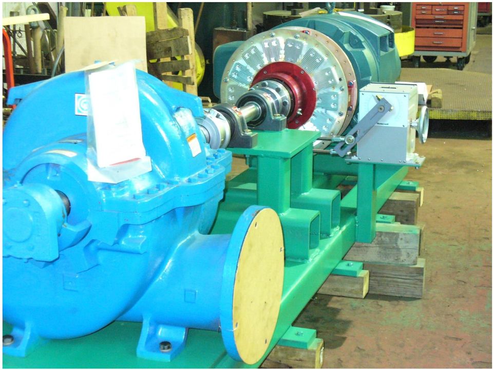
3 What is a Magnetic Coupling? Zero Contact Coupling Device Conductor and Magnet Conductor Attaches to Motor Magnets Attach to Pump or Pedestal Stand

4 How Does it Work The Motor Begins Rotating with No Load As the Motor Ramps Up to Full RPM, the Magnets On the Pump Begin to Rotate Using Magnetic and Centrifugal Forces The Motor Will Always Run at Full RPM, While the Pump Can Be Adjusted Using Actuation and Linkage Arms This Can Be Calibrated to Coincide With Flow Monitoring to Act as a Variable Drive

5 Applicable Pump Types Centrifugal Split Case End Suction Vertical Turbine

6
7

8

9 What Types of Magnetic Couplings are Available

10 Vertical Coupling Vertical ASD Adjustable Speed Drive Coupling Enclosed in Riser Housing 4-20mA Calibration

11 Horizontal Fixed Gap Soft Start Reduces Start Up Amp Load on Motor No Speed Adjustment Motor Starts with Zero Load and Pump Begins Spinning After

12 Horizontal ASD Adjustable Speed Drive Actuator Drives Linkage Arms Increasing Gap Reduces Speed Decreasing Gap Increases Speed

13 Applications Water Wastewater Power Coal Irrigation HVAC

14 Gypsum Plant

15 Wastewater Treatment Plant

16 Fresh Water Plant

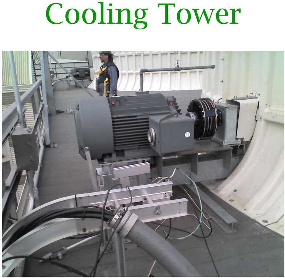
17 Cooling Tower
18 Any Questions??

19 Magnetic Coupling Pump Skid

20 Magna Drive Pump Skid Parts Welded Steel Base Structure Welded Steel Actuator Stand Welded Steel Bearing Pedestal Motor Magnetic Coupling Pump Coupling Guards

21 Fabrication of Pump Skid AutoCAD Dimensional Design of Finished Product Center Line Height is of the Utmost Importance Drawings are Based on Customers Needs and Current Specifications Goal of Skid is to Provide To Provide Turn-Key Pump Solution
22 Gather Parts & Materials Square Tube Steel Plate Steel Schedule 80 Pipe Angle Iron Expanded Metal I Beam Shaft Collar Flange-Mounted Steel Ball Bearing Square Head Jack Bolts Grid Style Coupling Pedestal Bearings Compression Fittings Copper Tubing
23 What Types of Machinery is Used?
24 Welder
25 Jig Mill
26 Knee Mill
27 Engine Lathe
28 Prepare the Base Structure Lay out Tube Steel to One End of Work Bench Weld Foot Plates Across Tube Steel Flip Structure Weld Motor, Pedestal and Pump Base Plates to Tube Steel
29 Machine Base Structure Machine Motor Bolt Slots Drill and Tap Pedestal Bolt Holes Drill and Tap Pump Bolt Holes Drill Base Lag Bolt Holes Machine Motor, Pedestal and Pump Plate Flat Cut Schedule 80 Pipe and Weld into Base Lag Bolt Holes Clean Off All Grease and Oil, Cover Machined Surfaces and Paint
30 Manufacturing Bearing Pedestal
31 Purpose of the Pedestal Pedestal Bearing Provides the Necessary Load Handling for the Magnetic Coupling The Bearing on the Pump is NOT Strong Enough to Handle the Weight of the Magnet Thus a More Robust Shaft and Bearing are Necessary
32 Pedestal Needs to be Square The Bearing Faces on the Pedestal Must be Square to Prevent Side Loading and Ultimate Bearing Failure To Do This.
33 Squaring Pedestal Machine Both Ends or the Tube Steel and Weld to Pedestal Base Plate Mill Bottom of Base Plate Square to Machine Table Machine All Sides of the Plate to Obtain Proper Lengths Stand Pedestal Upright and Use 2 Planes to Square the Piece Mill Nearside of Pedestal Flat for 1 Bearing Face and Cut Bearing Bolt Holes Machine Bearing Hole in Center of Bearing Face Allowing only.002 Clearance Rotate Pedestal and Square to the Table (Again Using 2 Planes) Zero Piece to Table Using Bearing Hole Cut in Previous Step Drill and Tap Bearing Bolt Holes Mill Far Side Flat to Establish 2 Square Bearing Faces
34 Building Pedestal Stand Attach Bearings to Stand and Bolt in Place Bearings Come With the Ability to Interchange Between Floating and Fixed Make the Motor Side the Floating Bearing Feed Shaft Through Bearings
35 Testing Bearing Pedestal Testing the Bearing Pedestal is Important A Lathe Chuck is Used on the Load Side to Simulate the Weight of the Magnetic Coupling Motor is Run at Operating Speeds to Verify Proper Shaft Alignment
36 Holds the Actuator That Controls the Speed of the Unit Uses a Fixed Linkage Arm and an Adjustable Linkage Arm to Move Magnet In and Out Motor Stays Same Speed, Pump Rotates Slower Based on Gap Between Magnets and Conductors Actuator Stand
37 Again Must Be Square Machine Top End of Bracket for Reference Point Establish Zero Machine Near Side Shaft Hole and Drill Nearside Bolt Hole Pattern Flip Bracket, Zero Using Reference From Above Machine Far Side Shaft Hole and Drill Bolt Hole Pattern Weld to I Beam, Noting Position of ½ Hole Location Take Shaft Material and Mill 4 Sides To Create Square Ended Shaft to Fit Into Actuator Machine to Length and Machine Bearing Fit Into Shaft Machine Slot in Drive Arm per Drawing Hand Grind Outside End Hand Grind Clamp Coupling End to Fit Square, Align and Butt Together Clamp Couplings Center Drive Arm to Clamp Couplings and Weld Into Place
38 Finished Actuator Stand
39 Any Questions??
40 Assembling the Pump Skid
41 If Everything Is Done Right. The Key to Assembling the Pump Skid is Shaft Alignment The Pump Needs to be Lower than the Bearing Pedestal and the Bearing Pedestal Needs to be Lower than the Motor The Object is to Bolt the Pump Directly to the Skid and Shim the Pedestal to Align the Shafts At This Point the Pedestal is Bolted Tight and the Motor is Shimmed and Aligned to the Now Immovable Pedestal
42 Importance of Shaft Alignment Over 90% of All Bearing Failure is Due to Shaft Misalignment Use Proper Equipment (Laser, Dial Indicators or Feeler Gauges) for Aligning Motors to Equipment Using a PEN is NOT Considered an Acceptable Method
43 Procedure for Assembling Skid Set Pump Onto Pump Base Plate and Start Bolts Into Bolt Holes Set Bearing Pedestal Onto Bearing Pedestal Base Plate and Start Bolts Into Bolt Holes Set Motor Onto Motor Base Plate and Start Bolts Into Bolt Holes Magnetic Couplings Need a Certain Distance Between Shaft Ends to Operate Effectively At this Time; Set the Bearing Pedestal Shaft To Allow for an Acceptable Distance
44 Procedure for Assembling Skid Install the Flexible Coupling to the Pump Shaft and Bearing Pedestal Shaft Align Shafts to Within.005 on the Horizontal Axis and the Angular Offset Tighten Down Pump and Bearing Pedestal Re-Check Alignment
45 Installing Magnetic Coupling Torque Compression Couplings on Both Pedestal and Motor Shafts Take TIR Reading to Verify Run-Out is Within Tolerance Install Magnetic Coupling Assembly to Pedestal and Torque Hub Bolts Using Motor Jacking Bolts, Bring Motor into Magnetic Coupling Assembly and Torque Hub Bolts
46 Aligning Magnetic Coupling Shaft Alignment with Magnetic Couplings is Different from Rigid Couplings There is Greater Tolerance Due to the Distance Between the Conductor Plates and the Magnets Tolerance are.030 Versus.003 With a Rigid Coupling In This Instance, Feeler Gauges are Used to Determine the Gap Between The Conductors and the Magnets Shim the Motor to the Appropriate Height and Align the Gaps at 90 Degree Intervals
47 Actuating The Unit Align Actuator Stand with Magnetic Coupling Linkage Arm and Weld Onto Base Install Actuator Shaft, Actuator Drive Arm, Actuator Bearing and Gear Operator Onto Actuator Stand Install Actuator to Gear Operator Install Linkage Arms and Adjust Actuator to Meet Operating Requirements Install Copper Tubing Air Lines and Compression Fittings to Actuator Calibrate Actuator Using Computer Calibration
48 Install Coupling Guards Coupling Guards are Needed to Protect Operator from Injury
49 Install Pump Skid at Plant Pump Skid is to be Lined Up to Piping System and Bolted Into Place Lag the Skid Into the Floor Using Lag Bolt Holes in Skid Grout Skid Into Place
50
51 Cautionary Tales
52 Noise Problems Because of the Magnetic Properties of the Coupling, Heat is Produced During Operation To Combat This, Cooling Fins are Located on the Exterior of the Conductor Plates Magnetic Couplings Therefore are Inherently Loud Covering the Couplings with Blankets to Reduce the Noise is a Bad Idea Too Much Heat Cracks and Destroys the Conductor Plates
53 Bolt Torque Bolts are Given Torque Values for a Reason. Be Sure to Torque All Bolts to the Recommended Specifications Compression Couplings Will Slip Hub Bolts and Base Bolts Will Vibrate Out Both Instances Causes Misalignment and Ultimately; Failure
54 Compression Coupling Shaft Clearance Coupling Hubs are Sent from the Factory Undersized Machining is Needed to Size Hub to Shaft Size No More than.002 is Acceptable or Compression Coupling Will Not Compress Hub to Shaft
55 Machining Problems If During the Machining Process Piece May Move, Causing Loss of Centerline Bearing Failure Due to Heat Build Up Inability to Align Equipment Due to Lack of Centerline Adjustment Bolt Hole Pattern Cut Improperly
56 Conclusion Magnetic Couplings are Viable Alternatives to VFD Motors They Do Not Require as Many Controls and Come Custom Made and Ready to Install Also, They Are Less Costly to Repair and Can Tolerate Harsher Conditions
57 Conclusion Manufacturing a Pump Skid Takes Precision Engineering and Operator Execution Whatever You Are Producing, Remember the 3 Biggest Rules 1 Am I Square? 2 Am I Aligned Horizontally and Vertically 3 Measure Twice, and Cut Once!!!
58 Any Questions??
59 THANK YOU!!!!
Field Application Note
 Field Application Note Reverse Dial Indicator Alignment RDIA Mis-alignment can be the most usual cause for unacceptable operation and high vibration levels. New facilities or new equipment installations
due to uncertainty. This, in turn, has a direct impact on equipment availability and maintenance costs. Unfortunately, due to misconceptions and
 due to uncertainty. This, in turn, has a direct impact on equipment availability and maintenance costs. Unfortunately, due to misconceptions and pressure from plant operators to get "back on line", it
Shaft Alignment White Paper
 Shaft Alignment White Paper Despite the best efforts to precisely align rotating machinery shafts, dynamic movement (commonly believed to be due to the thermal growth of the machine casings) has resulted
Lathe Milling Attachment
 Lathe Milling Attachment By L C. MASON BY CLEVERLY stacking cold-rolled flat stock together, T-slots and slide for this lathe milling attachment are made without costly machinery. In fact, only two tools,
Fire Pump Applications
 Fire Pump Applications Installation & Maintenance Manual Universal Joint Driveshafts www.cumminsfirepower.com Table of Contents Section 1 General 1.1 Introduction 1.2 Safety Precautions 1.3 Warranty Statement
GMC 2013: Piping Misalignment and Vibration Related Fatigue Failures
 GMC 2013: Piping Misalignment and Vibration Related Fatigue Failures www.betamachinery.com Authors/Presenters: Gary Maxwell, General Manager, BETA Machinery Analysis Brian Howes, Chief Engineer, BETA Machinery
F HIT O E PAP S ER GRUND W ALIGNMENT GENERAL
 GRUND W F HIT O E PAP S ER ALIGNMENT by Greg Towsley W ith requirements of organizations to cut costs and manage operation and maintenance budgets better, minimizing equipment downtime has become increasingly
Practical Alignment Tools and Techniques
 Practical Alignment Tools and Techniques Bruce Lehmann Sr. Engineer, Thin Kerf Technologies Inc Accurate sawing requires attention to proper alignment and maintenance. Alignment is critical to modem sawmills
2100 AD 015 0009 Mirror Elevator Ball Nut Replacement Procedure
 2100 AD 015 0009 Mirror Elevator Ball Nut Replacement Procedure Derek Guenther 1/28/2015 Rev. Purpose The purpose of this document is to describe the procedure necessary to replace one of the ball nuts
Understanding Shaft Alignment: Thermal Growth. Published in Maintenance Technology 1/2003
 Understanding Shaft Alignment: Thermal Growth Published in Maintenance Technology 1/2003 Part two of a four-part series that will cover alignment fundamentals and thermal growth, and highlight the importance
Permanent Magnetic Generator Construction Manual
 Permanent Magnetic Generator Construction Manual http://hojomotor.com Our Team Doing an On-site Assembly in Peru http://hojomotor.com Section 1) Introduction This manual describes how to build a 'permanent
Mechanical Installation
 Page -1-1. INTRODUCTION AND PURPOSE 1.1. This specification covers the installation, testing and precommissioning of mechanical equipment. Work is to be performed in conjunction with the manufacturer s
SLACK PERFORMANCE KARTS
 SLACK PERFORMANCE KARTS SET UP GUIDE Thank you for purchasing a 2013 Slack Axiom Chassis. Performance Mfg. strives to provide you with the very best chassis and components on the market today. Your satisfaction
AC Electric Motors best practice
 If you want to learn more about best practice machinery maintenance, or world class mechanical equipment maintenance and installation practices, follow the link to our Online Store and see the Training
Coal Handling Plant Alignment Standards For Shaft To Shaft Alignment. By Makarand Joshi M.Tech
 Coal Handling Plant Alignment Standards For Shaft To Shaft Alignment By Makarand Joshi M.Tech 1.0 Abstract: - Shaft alignment is a technical skill that is not common in the construction and maintenance
OHIO University Mechanical Engineering Summary Report: Human Power System for Small Appliances and Machinery
 OHIO University Mechanical Engineering Summary Report: Human Power System for Small Appliances and Machinery Appalachian Human Power Brad Bundy Ben Chovan Zach Fetchu Ed Passarrelli Ryan Tedford Will Zaylor
APPENDIX F VIBRATION TESTING PROCEDURE
 APPENDIX F VIBRATION TESTING PROCEDURE Appendix F SPS-F-1 of 14 VIBRATION PERFORMANCE TESTING I. General Perform a vibration analysis on all motor driven equipment listed below after it is installed and
SELF-STEERING AXLE TABLE OF CONTENTS
 SELF-STEERING AXLE TABLE OF CONTENTS Section 1 - Introduction Section 2 - Pre-Installation Check List Section 3 - Ride Height Adjustments Section 4 - Suspension Mount Section 5 - Axle Mount Section 6 -
Owner s Manual. Models: 2S5P & 3S5P OPERATION AND MAINTENANCE OF SELF-PRIMING CENTRIFUGAL TRASH PUMPS PEDESTAL DRIVE
 Owner s Manual Models: 2S5P & 3S5P OPERATION AND MAINTENANCE OF SELF-PRIMING CENTRIFUGAL TRASH PUMPS PEDESTAL DRIVE WARNING!! Installation & Operating Instructions Self-Priming Centrifugal Pump DO NOT
PowerLine Magnetic-Laser Pulley Alignment System Instructions
 MONARCH INSTRUMENT 15 COLUMBIA DRIVE AMHERST, NEW HAMPSHIRE 03031 PHONE: 603-883-3390 FAX: 603-886-3300 E-mail: sales@monarchinstrument.com Web site: www.monarchinstrument.com PowerLine Magnetic-Laser
ALIGNMENT PITFALLS - HOW TO IDENTIFY AND ELIMINATE THEM
 ALIGNMENT PITFALLS - HOW TO IDENTIFY AND ELIMINATE THEM by Robert D. Skeirik Vibration Group Marketing Manager for Computational Systems, Inc Knoxville, Tennessee ABSTRACT In theory, machine alignment
Power Cube Open Source Ecology Page 1. Power Cube. Version 4
 Power Cube Open Source Ecology Page 1 Power Cube Version 4 Power Cube Open Source Ecology Page 2 Contents Table of Contents Power Cube... 1 Contents...2 Introduction... 3 Bill Of Materials...4 Discrete
TRANS-05, Torque Tube Removal, Rebuilding, and Installation
 TRANS-05, Torque Tube Removal, Rebuilding, and Installation Tools Metric Wrench Set Metric Socket Set Jack Stands (6 minimum) Floor Jack 8mm Cheesehead socket (also referred to as 12 point internal socket
HORIZONTAL PUMPING SYSTEM
 HORIZONTAL PUMPING SYSTEM BORETS U.S. INC. PERFORMANCE TECHNOLOGY INNOVATION Horizontal Pumping System What is HPS? HPS classification, Pumps, Stages, Impellers, Curves/Performance, Components Why use
COMMISSIONING AND START-UPS OF NEW UNITS (PUMPS)
") by Wallace E. (Ed) Wilcox Staff Machinery Engineer Chevron Energy Technology Company Houston, Texas Mike White Field Service Manager and Gordon Parks Senior Field Engineer Sulzer Pumps (US) Inc. Portland,
by Wallace E. (Ed) Wilcox Staff Machinery Engineer Chevron Energy Technology Company Houston, Texas Mike White Field Service Manager and Gordon Parks Senior Field Engineer Sulzer Pumps (US) Inc. Portland,
ALIGNMENT. Pump and Driver Alignment
 ALIGNMENT Pump and Driver Alignment Alignment Subject: Pump and Driver Alignment In the pump business alignment means that the centerline of the pump is aligned with the centerline of the driver. Although
Assembly Instructions for the InteliTrack 3000 Rail Tracking System
 Assembly Instructions for the InteliTrack 3000 Rail Tracking System InteliTrack is a trademark of Sedona Solar Technology. Sedona Solar Technology 16 April 2013 1 1. Before you begin WARNING Safety equipment
PowerLine Magnetic-Laser Sheave Alignment System Instructions
 PowerLine Magnetic-Laser Sheave Alignment System Instructions The PowerLine Magnetic-Laser Sheave Alignment System laser aligns belts, pulleys, sheaves, sprockets, gear trains, rollers, platforms, conveyors,
ROTATING MACHINES. Alignment & Positioning of. Fast, easy and accurate alignment of rotating machines, pumps, drives, foundations, etc.
 Alignment & Positioning of ROTATING MACHINES Fast, easy and accurate alignment of rotating machines, pumps, drives, foundations, etc. To compete in today s marketplace, you have to outperform your competitors
BSM MOTOR DRIVEN CENTRIFUGAL PUMPS
 PRINCIPLE OF OPERATION A hydraulically and dynamically balanced impeller with raised vane sections discharges liquid as a result of the centrifugal force developed in rotation. The head developed is entirely
Part #20195 WORKBENCH BRACKET SYSTEM INSTRUCTIONS
 Part #20195 WORKNH RKT SYSTM INSTRUTIONS The astwood Workbench rackets are fabricated from 3/16" thick, high strength steel and are designed to be used with wood or steel legs and framing members. Precision
Slide the new steering column shaft through the steering column from the driver compartment.
 Slide the new steering column shaft through the steering column from the driver compartment. Push the column shaft through the steering column until the machined end is out past the column lower bushing.
Step-by-step instructions:
 Spark plug thread repair for Ford Triton cylinder heads Step-by-step instructions: Identification Installation Verification Specifically designed and tested for 4.6L, 5.4L, and 6.8L 2 and 4 valve heads,
ALLDATA Online - 2006 Dodge Truck RAM 2500 Truck 2WD L6-5.9L DSL Turbo VI... Service and Repair
 Page 1 of 15 Home Account Contact ALLDATA Log Out Help PAUL REDEHOFT Select Vehicle New TSBs Technician's Reference Component Search: OK 2006 Dodge Truck RAM 2500 Truck 2WD L6-5.9L DSL Turbo VIN C Conversion
The Bonelle Tool and Cutter Grinder
 The Bonelle Tool and Cutter Grinder The grinder was constructed about 1987 and exhibited at the 89th Model Engineering exhibition where it was awarded a bronze medal (see ME Vol164 No 3868 page 273). Subsequently
The "DAVID" Steam Engine By Alan Marconett Hobbit Engineering HTTP://WWW.HobbitEngineering.com Alan@HobbitEngineering.
 The "DAVID" Steam Engine By Alan Marconett Hobbit Engineering HTTP://WWW.HobbitEngineering.com Alan@HobbitEngineering.com (c) 2/20/03 The David steam engine is a simple oscillating steam engine, many plans
Pipe Cutting and Beveling Clamshells
 Pipe Cutting and Beveling Clamshells Who We Are One Company, Total Support, Complete Solutions For more than a century, Hydratight has provided world-class bolted joint solutions and continues to set international
Select Radiators Installation Guide
 Select Radiators Installation Guide Table of Contents Informational Symbols...3 Before You Begin...4 Select Rough-In... 5 Connection Installation...6 Optional Piping Arrangements...7 Conventional Wall
METAL-TURNING LATHE Built from Stock Parts
 by Frank Beatty USING STANDARD PARTS and stock materials that are available almost anywhere, you can build this metalworking lathe with only a few tools. Because of simplification of the assembly in order
Module 5 Couplings. Version 2 ME, IIT Kharagpur
 Module 5 Couplings Lesson 1 Introduction, types and uses Instructional Objectives At the end of this lesson, the students should have the knowledge of The function of couplings in machinery. Different
1. Lay out 2 pieces of 7/8" tubing and mark for bending as shown. Remember that the bend is in the shaded area as shown below in Figure 1.
 MINI BIKE PLANS Page 1 INTRODUCTION Before starting to build your Mini-Bike, be sure that you have all the parts shown on the material list. You will note that tubing has been used in the construction.
Fuel Injection Pump, Rotary (005-014)
") Fuel Injection Pump, Rotary View Related Topic Page 1 of 30 Fuel Injection Pump, Rotary (005-014) Table of Contents Summary General Information Preparatory Steps Remove Front Gear Train Rear Gear Train
Fuel Injection Pump, Rotary View Related Topic Page 1 of 30 Fuel Injection Pump, Rotary (005-014) Table of Contents Summary General Information Preparatory Steps Remove Front Gear Train Rear Gear Train
Propeller Equipment Sale. For Questions please contact Dan Cork Propdoc@aol.com 918-636-3567
 Propeller Equipment Sale For Questions please contact Dan Cork Propdoc@aol.com 918-636-3567 Propeller Equipment Sale The equipment for sale is used in the repair and overhaul of aircraft propellers. Propeller
The India Thermit Corporation
 The India Thermit Corporation World Leaders in Rail Welding Alumino - Thermic Welding Flash Butt Welding The Company The India Thermit Corporation (ITC) is the world's largest executor of rail welds. We
Overview. Milling Machine Fundamentals. Safety. Shop Etiquette. Vehicle Projects Machine Shop
 Overview Milling Machine Fundamentals Wayne Staats, UW-Madison FSAE Safety Shop Etiquette Before Machining Indicating Calculating Feeds and Speeds Machining Maintenance Safety Respect the machines Common
Home"" """"> ar.cn.de.en.es.fr.id.it.ph.po.ru.sw
 Home"" """"> ar.cn.de.en.es.fr.id.it.ph.po.ru.sw Milling of Grooves, Elongated Slots and Break-throughs - Course: Techniques for machining of material. Trainees' handbook of lessons (Institut fr Berufliche
H EAD TUBE BASICS. Figure 1 - Head tube, front fork and hardware
 H EAD TUBE BASICS Figure 1 - Head tube, front fork and hardware This tutorial will cover some of the basics you need to know when pulling apart the steering system of a bicycle for repair or use on one
FTC 2015-2016 DIY Mountain Build Guide
 FTC 2015-2016 DIY Mountain Build Guide Assembly Instructions Check out the DIY2015-2016 Prints and BoM for individual part details. Release 1.0 9/10/15 Page 1 This guide and Bill of Materials are for constructing
SUPPLEMENTAL TECHNICAL SPECIFICATIONS BI-DIRECTIONAL STATIC LOAD TESTING OF DRILLED SHAFTS
 July 14, 2015 1.0 GENERAL BI-DIRECTIONAL STATIC LOAD TESTING OF DRILLED SHAFTS This work shall consist of furnishing all materials, equipment, labor, and incidentals necessary for conducting bi-directional
Documenting Results to Validate Energy Savings Projects: Case Study of Direct Drive Cooling Tower Installations: Before and After
 Documenting Results to Validate Energy Savings Projects: Case Study of Direct Drive Cooling Tower Installations: Before and After Roman Wajda, Baldor Electric Company ABSTRACT Documenting the actual energy
Things you need to assemble the tube actuator. Left to right. are small piece of masking tape, super glue,pen knife and small
 Things you need to assemble the tube actuator. Left to right are small piece of masking tape, super glue,pen knife and small crosspoint screwdriver. You will also need a few drops of light oil. Begin by
Resharpening Companion
 Resharpening Companion 10950 Correct Angles, Pictures, and Step-By-Step Instructions The Resharpening Companion is meant to be a guide and quick reference to help you resharpen. It is not meant to replace
OHV / OHVL Type OH3 Vertical Inline Pumps ISO 13709 (API 610)
") OHV / OHVL Type OH3 Vertical Inline Pumps ISO 13709 (API 610) The Heart of Your Process OHV / OHVL Type OH3 Vertical Inline Pumps ISO 13709 (API 610) OHV OHVL OHV/OHVL Sales Presentation slide
OHV / OHVL Type OH3 Vertical Inline Pumps ISO 13709 (API 610) The Heart of Your Process OHV / OHVL Type OH3 Vertical Inline Pumps ISO 13709 (API 610) OHV OHVL OHV/OHVL Sales Presentation slide
10 TON HYDRAULIC PRESS
 10 TON HYDRAULIC PRESS Model Nos. CSA10F and CSA10B OPERATING & MAINTENANCE INSTRUCTIONS 0200 SPARE PARTS and SERVICING Please contact your nearest dealer, or CLARKE International, on one of the following
TRS 090/105 Compressor. Repair Procedures
 TRS 090/105 Compressor Repair Procedures GENERAL FGG All repair and service operations should be performed on a clean bench and with the use of clean tools. Use genuine parts and correct tools for all
2008 ACCORD - Front Knuckle/Hub/Wheel Bearing Replacement (page 18-13)
") 2008 ACCORD - Front Knuckle/Hub/Wheel Bearing Replacement (page 18-13) Exploded View Special Tools Required Ball joint remover, 28 mm 07MAC-SL0A202 Hub dis/assembly tool 07GAF-SD40100 Bearing driver attachment,
2008 ACCORD - Front Knuckle/Hub/Wheel Bearing Replacement (page 18-13) Exploded View Special Tools Required Ball joint remover, 28 mm 07MAC-SL0A202 Hub dis/assembly tool 07GAF-SD40100 Bearing driver attachment,
Street-Lynx. Reilly MotorSports, Inc. Installation Manual
 Street-Lynx By Reilly MotorSports, Inc. Installation Manual 1 1- Begin by removing your original rear suspension disconnect your brake lines, E-brake cables, and remove the driveshaft. To prevent fire
ALIGNMENT OF VERTICAL SHAFT HYDROUNITS
 FACILITIES INSTRUCTIONS, STANDARDS, AND TECHNIQUES VOLUME 2-1 ALIGNMENT OF VERTICAL SHAFT HYDROUNITS Issued 1967 Darrell Temple Revised 1988 William Duncan Jr. Revised 2000 Roger Cline HYDROELECTRIC RESEARCH
VERTICAL TURBINE AND PROPELLER PUMPS
 VERTICAL TURBINE AND PROPELLER PUMPS INTRODUCTION Vertical Turbine and Propeller Pumps Model 7000 Series Turbine Pump Model 800 Series Axial Flow Propeller Pump Model 800 Series Mixed Flow Propeller Pump
SHAFT VERSUS FOOT ALIGNMENT TOLERANCES A Critique of the Various Approaches by Alan Luedeking, Ludeca, Inc.
 SHAFT VERSUS FOOT ALIGNMENT TOLERANCES A Critique of the Various Approaches by Alan Luedeking, Ludeca, Inc. The only correct way to express shaft alignment tolerances is in terms of alignment conditions
S&W Race Cars and Components, Inc.
 S&W Race Cars and Components, Inc. 11 Mennonite Church Road Spring City, PA 19475 TECH & INFORMATION: 610-948-7303 ORDERS: 1-800-523-3353 OFFICE FAX: 610-948-7342 E-Z INFO FAX 610-792-1234 CAUTION!!! -
BARREL ALIGNMENT- A CRITICAL FACTOR IN REDUCING EXTRUDER WEAR
 BARREL ALIGNMENT- A CRITICAL FACTOR IN REDUCING EXTRUDER WEAR Jeff A. Myers- BARR Inc., Onsted, MI Mike Puhalla Milacron, Batavia, OH Abstract As processors increase the demand on the extruder for increased
PRE-ASSEMBLED INSTALLATION INSTRUCTIONS FOR PACB SERIES COAL FIRED OVENS
 PRE-ASSEMBLED INSTALLATION INSTRUCTIONS FOR PACB SERIES COAL FIRED OVENS OVENS MANUFACTURED BY: EARTHSTONE OVENS-6717 SAN FERNANDO RD GLENDALE CA 91201 TELEPHONE: 800-840-4915 818-553-1134 FAX: 818-553-1133
Pump and Valve Components and Maintenance
 Pump and Valve Components and Maintenance Outline: 1. Split case and End Suction pumps, industry in the 21 st century, cost of ownership, and performance tips 2. Split case Pumps features, maintenance,
A Practical Guide to Pulley Alignment
 A Practical Guide to Pulley Alignment Care has been taken by the authors, PRUFTECHNIK LTD, in the preparation of this publication. It is not intended as a comprehensive guide to alignment of process machinery,
Vertical Multistage Centrifugal Electric Pumps SV2-4-8-16 Series NEW LASER TECHNOLOGY
 Vertical Multistage Centrifugal Electric Pumps SV2-4-8-16 Series NEW LASER TECHNOLOGY TYPICAL APPLICATIONS Water supply Transfer and distribution from water systems Pressure boosting in apartment buildings
The Lifetime Reliability Solutions Certificate Course in Maintenance and Reliability Module 4 Precision Maintenance Techniques for Machinery
 Phone: Fax: Email: Website: +61 (0) 402 731 563 +61 (8) 9457 8642 info@lifetime-reliability.com www.lifetime-reliability.com The Lifetime Reliability Solutions Certificate Course in Maintenance and Reliability
Building a Small Horizontal Steam Engine
 T Building a Small Horizontal Steam Engine HE small engine described in this article was built by the writer in his spare time about an hour a day for four months and drives the machinery in a small shop.
Rebuild Instructions for 70001 and 70010 Transmission
 Rebuild Instructions for 70001 and 70010 Transmission Brinn, Incorporated 1615 Tech Drive Bay City, MI 48706 Telephone 989.686.8920 Fax 989.686.6520 www.brinninc.com Notice Read all instructions before
drawworks WWL started manufacturing drawworks over 40 years ago under the BDW brand. draw on our experience BDW Model 2000-MX or MXE
 Our experience benefits our customers WWL started manufacturing drawworks over 40 years ago under the BDW brand. Within the Oil & Gas drilling industry, the BDW brand is known as the Cadillac of drawworks.
SERIES ASM NEOPRENE/EPMD FLANGED SINGLE SPHERE CONNECTOR CONNECTORS. Pressures to 225 PSIG (15.51 barg) Temperatures to 230ºF (110ºC)
 Temperatures to 230ºF (110ºC)") APPLICATIONS Process Industry Weak Acids Alkalies Compressed Air Pulp & Paper MODELS ASM - Flanged Connection OPTIONS Control Rods Oil & Gas Water & Waste Pump suction & discharge Sea water Chemical lines
APPLICATIONS Process Industry Weak Acids Alkalies Compressed Air Pulp & Paper MODELS ASM - Flanged Connection OPTIONS Control Rods Oil & Gas Water & Waste Pump suction & discharge Sea water Chemical lines
Mobile field balancing reduces vibrations in energy and power plants. Published in VGB PowerTech 07/2012
 Mobile field balancing reduces vibrations in energy and power plants Published in VGB PowerTech 07/2012 Dr. Edwin Becker PRÜFTECHNIK Condition Monitoring PRÜFTECHNIK Condition Monitoring GmbH 85737 Ismaning
A Practical Guide to Shaft Alignment
 A Practical Guide to Shaft Alignment Care has been taken by the authors, PRUFTECHNIK LTD, in the preparation of this publication. It is not intended as a comprehensive guide to alignment of process machinery,
IEC Three Phase AC Motors (Aluminum Frame) Installation & Operating Manual
 Installation & Operating Manual") IEC Three Phase AC Motors (Aluminum Frame) Installation & Operating Manual 7/09 MN301 Table of Contents Section 1 General Information.................................................. 1-1 Overview........................................................
IEC Three Phase AC Motors (Aluminum Frame) Installation & Operating Manual 7/09 MN301 Table of Contents Section 1 General Information.................................................. 1-1 Overview........................................................
EZ-48-3AB-125-35 Weather Station Mounting Tripod and Mast
 EZ-48-3AB-125-35 Weather Station Mounting Tripod and Mast EZ-125-35M 35 Mast Extension (Optional) EZ-125-SK Stake Kit (Optional) EZ-46-3 Tar Pad Kit (Optional) EZ-GWA Guy Wire Kit (Optional) Ambient Weather
BOWIE PUMPS OPERATION - MAINTENANCE
 BOWIE PUMPS OPERATION - MAINTENANCE PUMPING PRINCIPLE: The meshing owieeof the gears cause a slight depression, with the resulting enmeshing of the gears causing a vacuum drawing the fluid being pumped
DiscPlus DX195 and DX225 Air Disc Brakes
 Revised 11-04 Technical Bulletin Revised 1 Technical 11-04 Bulletin DiscPlus DX195 and DX225 Air Disc Brakes Inspection, Installation and Diagnostics Air Disc Brake Inspection Intervals and Procedures
16 April 2012 1032011-F 1994-2002 Dodge Adjustable Track bar with Relocation Bracket 1
 16 April 2012 1032011-F 1994-2002 Dodge Adjustable Track bar with Relocation Bracket 1 BD Adjustable Track Bar w/bracket Dodge 2500-3500 4WD Models 1994-2002 Dodge 1500 4WD Model 1994-2001 P/N# 1032011-F
CHAPTER 65 TAIL ROTOR DRIVE SYSTEM. Section Title Page
 CHAPTER 65 TAIL ROTOR DRIVE SYSTEM Section Title Page 65-00 Description........................................ 65.1 65-10 Tail Rotor Drive Fan Shaft.............................. 65.1 65-20 Tail Rotor
Guidelines for Earthquake Bracing of Residential Water Heaters
 Guidelines for Earthquake Bracing of Residential Water Heaters Department of General Services Division of the State Architect 1102 Q Street, Suite 5100 Sacramento, CA 95814 Phone: (916) 324-7099 Fax: (916)
Pump Specifications 250 Series Submersible Sump / Effluent Pump 2 Solids handling
 Pump Specifications 250 Series Submersible Sump / Effluent Pump 2 Solids handling 250_P1 R10/7/2015 Copyright 2015 Liberty Pumps Inc. All rights reserved. Specifications subject to change without notice.
Jet Propulsion System
 This repair manual is valid for the following jet pump variants: 0333_ 0 V3 007 3. 033_ 0 V 007 3. 0380_ 3 V 007 3. 0335_ 3 V 007 3. 033_ 66 V 008. 0338_ 66 V 008. Table of Contents Before you begin working
Q&A Session for Advanced Ball Screws 102: Troubleshooting for Design Engineers
 Q&A Session for Advanced Ball Screws 102: Troubleshooting for Design Engineers Topic: Noise Q: Is there a way to predict/calculate noise on a ball screw? A: No, there is no way to calculate the noise of
FACILITY ACCREDITATION CHECKLIST #001 APPRENTICESHIP. Rating Code: Y = Yes * N = No * R = Required * AUDIT AREA: DATE: / / HAND TOOLS Y N R
 FACILITY ACCREDITATION CHECKLIST #001 APPRENTICESHIP Designated Trade: Level 1 2 3 4 Institution: Evaluator(s) / / Rating Code: Y = Yes * N = No * R = Required * * Please use a CHECKMARK under the appropriate
This little motorcycle has been designed
 MITE CYCLE You'll need only an "A" ration to run this midget motorcycle. by R. G. Fisher The Mite Cycle, with its builder, is shown above. A small one-cylinder engine provides the motive power. This little
STEADYfast Stabilizer Installation Notes Fifth Wheel and Travel Trailers 11/23/13
 STEADYfast Stabilizer Installation Notes Fifth Wheel and Travel Trailers 11/23/13 (See Supplemental Instructions for trailers with heavy duty round footplates and/or Power Leveling Systems) PHONE SUPPORT
Rules of Actuator and Guide Alignment in Linear Motion Systems
 Rules of Actuator and Guide Alignment in Linear Motion Systems By Gary Rosengren, Director of Engineering Tolomatic, Inc. About the Author Gary Rosengren is Director of Engineering at Tolomatic and has
No. 57 Receiver Sight No. 57 SML Receiver Sight No. 66 Receiver Sight
 No. 57 Receiver Sight No. 57 SML Receiver Sight No. 66 Receiver Sight MOUNTING AND ADJUSTING MOUNTING LYMAN NO 57 RECEIVER SIGHT The No. 57 Sight is designed primarily for rifles with round receivers.
FOR ANY QUESTIONS, PLEASE CALL US @ 727.347.9915 M-F 8:00a.m.-8:00p.m. EST. REAR BRAKES 1 AEROSPACE COMPONENTS 727.347.9915
 REAR BRAKES 1 AEROSPACE COMPONENTS 727.347.9915 REAR BRAKES Before getting started, remove all stock braking components. Pre-assembly of parts: Clean the bolts and the threads in the hat with acetone.
LG G5 Chassis Brace Gen 5 Camaro THE MOST POWERFUL HEADERS ON THE PLANET Brought to you by LG Motorsports 972-429-1963
 LG G5 Chassis Brace Gen 5 Camaro THE MOST POWERFUL HEADERS ON THE PLANET Brought to you by LG Motorsports 972-429-1963 Thank you for purchasing LG Motorsports products for your Gen 5 Camaro. Parts Inventory:
ANSI APPROVED 04/11/2014 ANSI APPROVED 08/17/2011. 45 Reaffirmation ANSI APPROVED 02/28/2014. 45 Reaffirmation ANSI APPROVED 05/06/2013
 STANDARDS STATUS REPORT As of November 4, 2015 Note: Dates in RED indicate the last action taken; Highlighted Items Indicate New/Open Items; Grey items have been closed Document TC Status Comments ASME
Successful Belt Maintenance. ADVANCED Maintenance Solutions
 Successful Belt Maintenance A research paper by ADVANCED Maintenance Solutions 7600 Delview Drive West Chester, OH 45069 Phone: 513-779-5880 Fax: 513-779-5881 Cell: 513-379-4574 rich@theadvancedteam.com
Competition 4 & 6 suspension Lift Toyota Landcruiser & nissan patrol
 Competition 4 & 6 suspension Lift Toyota Landcruiser & nissan patrol Competition suspension Product Guidelines Guidelines for sale and recommendation of 4 (100mm) and 6 (150mm) Lifts for Toyota Landcruiser
North Carolina FFA Association Agricultural Mechanics Career Development Event
 North Carolina FFA Association Three (3) of the following Agricultural Mechanics Performance Skills will be selected for the state competition. North Carolina FFA Association Agricultural Mechanics Performance
DTU Animal Cart Programme
 DTU Animal Cart Programme TECHNICAL 21 RELEASE PIPE AND ROLLER DONKEY CART AXLES Development Technology Unit, Department of Engineering, University of Warwick, Coventry, CV4 7AL UK, tel: +44 (0)1203 523523
PROTOTYPE DESIGN AND MANUFACTURING MANUAL
 PROTOTYPE DESIGN AND MANUFACTURING MANUAL DEPARTMENT OF MECHANICAL ENGINEERING RODNEY KATZ Rev. 0 TABLE OF CONTENTS Introduction... 1 PART I - Design... 2 1 First Step to Design... 2 2 Prototyping... 3
Owner s Manual Gantry Cranes
 Owner s Manual Gantry Cranes Fixed Height Gantry Crane MODEL NUMBER: SERIAL NUMBER: CAPACITY IN TONS: Telescoping Gantry Crane Bushman AvonTec 262-790-4200, 800338-7810, Fax 262-790-4200 www.bushmanavontec.com
Johnson Power Ltd. / MAINA GEAR COUPLINGS
 PGE 1 Johnson Power Ltd. / MIN GER OUPLINGS Johnson Power, Ltd. is now pleased to offer Maina gear couplings. Maina designs and manufactures a complete line of gear couplings and spindles for industrial
MEASURING WHEEL ALIGNMENT
 MEASURING WHEEL ALIGNMENT 2003-04 WHEEL ALIGNMENT Specifications & Procedures - Hummer - H2 Steering and vibration complaints are not always the result of improper alignment. One possible cause is wheel