Fire Pump Applications
|
|
|
- Alannah Butler
- 7 years ago
- Views:
Transcription
1 Fire Pump Applications Installation & Maintenance Manual Universal Joint Driveshafts

2 Table of Contents Section 1 General 1.1 Introduction 1.2 Safety Precautions 1.3 Warranty Statement 1.4 Basic Guidelines Section 2 Installation 2.1 Drive Shaft 2.2 Companion Flanges 2.3 Shaft Alignment 2.4 Vertical Offset 2.5 Horizontal Offset Section 3 Lubrication 3.1 Lubrication Procedure Section 4 - General Inspection Section 5 - Application Calculations Section 6 - Application Charts Section 7 - Dimensional Attributes Section 8 - Troubleshooting This Manual contains proprietary information to equipment produced by Cummins Fire Power or Cummins Inc. and is being supplied solely for the purpose of operating, maintaining and servicing the fire pump engine driveshaft application purchased from Cummins Fire Power. Copyright 2009, Cummins Fire Power Cummins Fire Power, LLC Rev toc-i

3 Section 1 - General 1.1 Introduction This manual provides information for the installation and maintenance of universal joint driveshafts intended for use with diesel engine drivers. Following proper installation and maintenance procedures produces the optimum results in shaft performance and safety. Cummins Fire Power Manuals should be considered part of the equipment. It is recommended to keep the manuals with the equipment. If the equipment is sold or traded, please transfer manuals to the new owner. All personnel responsible for operation and maintenance of the equipment should read and thoroughly understand this manual. Driveshafts shall be installed in accordance with the Standard for Installation of Stationary Pumps for Fire Protection, NFPA 20. It is recommended that a torsional analysis be conducted on the actual drive system arrangement. 1.2 Safety Precautions Warning: Read and understand all of the safety precautions and warnings before performing any repair. This manual contains the general safety precautions that must be followed to provide personal safety. Warning: Rotating shafts can be dangerous. Keep hands, body parts, long hair, or loose fitting clothing clear at all times. Warning: Rotating shafts can be dangerous. Follow all safety and lockout precautions during installation, maintenance and operation. Warning: Perform a walk around inspection and alert all area personnel that the equipment will be starting before operation. Caution: Consult applicable local and national safety codes for proper guarding of rotating members. Observe all safety rules when installing or servicing couplings and driveshafts. Warning: After performing maintenance, remove all tools and foreign materials, reinstall and securely fasten ALL guards, covers and protective devices. 1.3 Warranty Limited Warranty does not cover failures or damage due to abuse or neglect and including, but not limited to: shipping damage, improper storage, improper installation, unauthorized modifications or lack of maintenance. Cummins Fire Power is not responsible for incidental or consequential damages. Cummins Fire Power, LLC Rev Page 1

4 1.4 Basic Guidelines to Universal Joint Driveshafts Even though driveshafts have the unique capability of accepting both axial and offset movements, the following precautions must be taken: They must work in pairs. A universal joint, working at an angle, will vibrate if it is not cancelled by another joint. The second joint (opposite side of the shaft) must be working at the same angle and in the same plane. (See Figures 1 & 2) Figure The universal joint operating angle shall be within 1-3 degrees To determine the correct amount of working angle; a) Measure the length in inches from centerline of yoke bore(s) to centerline of opposing yoke bore(s). b) Measure parallel offset between centerline of drive and driven shafts. Figure Joint angles must be equal within ½ degree. Joints, working in pairs will vibrate if they are not working at the same angle within ½ degree. (See Figure 2) Yokes must be in phase (Figures 1 & 2). Joints, working in pairs, will vibrate if their yoke ears are not in the same plane Standard installation (Figure 1) requires that the input and output shafts be parallel In the alternate installation (Figure 2) the centerlines of the output and input shafts must intersect at the center of the driveshaft. Consult factory for installation using this method. Figure 3 The actual offset shall measure / inches per 12 inches of shaft length. Following this offset relationship will yield an operating angle of 1-3 degrees. Cummins Fire Power, LLC Rev Page 2
 Measure parallel offset between centerline of drive and driven shafts. Figure 1 1.4.2 Joint angles must be equal within ½ degree.")
5 Section 2 - Installation 2.1 Driveshaft Installation Clean flange faces removing all paints or contaminants from the surface. Examine mating surfaces for any damage or nicks in the machine finish. Failure to properly clean the mating surfaces can result in premature driveshaft connection failure Inspect companion flanges for proper installation (see Section 2.2) Compress driveshaft and place into position between mating flanges (see Figure 4). Large universal joint shaft assemblies are very heavy, use proper lifting equipment during installation. Carefully align pilot bore boss into/onto companion flange mating diameter. Align bolt holes on driveshaft flange with holes on companion flange. Secure flange to driveshaft with proper hardware. Extend shaft at slip section until pilot bore boss aligns with companion flange pilot bore boss. Align holes and secure flange. Figure Torque fasteners to proper specification (see Table B) Lubricate all joints, splines (where applicable) before startup. Lubricate until lubricant appears at all four bearing cap seals Verify offset and shaft operating angles Install proper shaft guarding prior to start up. 2.2 Companion Flange installation There are two types of mating flanges available for connecting the drive and driven unit shaft ends to the driveshaft. Type (1) SF standard flange accepts through bolting. Type (2) SLF large bore flange are drilled and threaded to accept fasteners or stud kit (see Figure 5). Stock bore companion flanges SF or SLF are bored with a plus minus tolerance and shall be a slip fit over mating shaft. Figure Align flange keyway with shaft key and gently tap flange onto shaft with soft face mallet. Take extreme care not to damage flange face or flange. If flange does not install easily, remove and retry. Note: The drive/driven shaft shall not extend out beyond the flange face or pilot bore/boss Tighten setscrew(s) to recommended torque (see Table C) Check concentricity of companion flange face and pilot. Maximum allowable TIR is on face and pilot (see Figure 6). Cummins Fire Power, LLC Rev Page 3

6 2.4 Vertical Offset Position (rotate) shaft so that the inboard shaft yokes are vertical as shown (Figure 8a & 8c) Measure distance from point A to B as shown (Figure 8a or 8c). Figure Thoroughly clean and inspect flange mounting face removing any oils, dirt, or contaminants. 2.3 Shaft Alignment The procedure below is based on a fire pump installation where the engine crankshaft centerline is on the same centerline as the pump when examined from the top view and parallel in the side view (see Figure 7). If installation requires another configuration, please consult factory customer service for assistance. For all measurements vernier caliper or dial indicator will be needed Measure distance from point C to D as shown in (Figure 8a or 8c) On Table A locate row of shaft Part Number being aligned Raise or lower drive or driven unit until measurements AB & CD are within the Vertical Offset Tolerance range as note in Table A When finished, measurements AB and CD must also have equal values within tolerance ranges identified in Table A. 2.5 Horizontal Offset Because the centerlines of the crankshaft and pump unit are designed to be on the same centerline, the horizontal offset alignment check is to confirm near zero misalignment Position (rotate) the shaft so that the inboard yokes are horizontal (Figure 8b or 8d) Measure distance from point J to K as shown (Figure 8b or 8d) Measure distance from point L to M as shown (Figure 8b or 8d). Figure See Table A and identify the proper row with applicable values of the shaft that is being installed. Cummins Fire Power, LLC Rev Page 4

7 2.5.5 Measured values at the four positions referenced (JK, LM, NP, RS) may not vary more than the published tolerance in the column listed as Horizontal Offset Tolerance as noted in Table A. Table A Weight in Shaft Listed Vertical Vertical Horizontal Offset lbs per Series Shaft PN Offset Offset Tolerance PN Measurement Tolerance (+ or -) series AB & CD (+ or -) JK, LM, NP & RS (inches) (inches) (inches) U U U U U U **Measurement taken from yoke side of flange face to far side of universal bearing plate as shown in the referenced Figures 8a-8d which are to be used for measuring instruction. For parts and service inquiries, please contact: Visit us on the web at: Cummins Fire Power, LLC 875 Lawrence Drive De Pere, WI Phone: in the US. Fax: Please provide Engine serial number or the Driveshaft serial no. and tag information. Cummins Fire Power, LLC Rev Page 5

8 Series ( ) Series U3101 U3172 ( ) Vertical Offset Sectional View Figure 8a Horizontal Offset Sectional View Figure 8b Cummins Fire Power, LLC Rev Page 6

9 Series 1610 Series 1880 ( ) Only Vertical Offset Sectional View Figure 8c Horizontal Offset Sectional View Figure 8d Cummins Fire Power, LLC Rev Page 7

10 Section 3 - Lubrication 3.0 Lubrication The majority of premature universal joint and slip spline failures are due to improper lubrication. Proper lubrication practice flushes contaminants from the bearings promoting maximum functional life. A high quality NLGI Grade 2 EP lithium grease is recommended for both universal joint and slip splines. Note: Do not use lubricants with molybdenum disulfide additives in universal joint bearings. Lubrication intervals vary depending on the application, installation environment, and operating conditions. Continuously operating assemblies should be lubricated every 200 operating hours. Limited usage joints should be lubricated every 6 months in protected environmental conditions, every 60 days in harsh environments. 3.1 Lubrication Procedure Using the proper NLGI Grade 2 lubricant, purge all four bearing seals of the universal joint. Pressure fill universal joint through fitting A in Figure 9. This flushes contaminants from each bearing assembly and assures all four are filled completely. Figure 9 Note: If any seal fails to purge, move the driveshaft from side to side and then reapply pressure to the fitting Lubricate slip splines through fitting B on the shaft assembly. Only shafts stamped Series ( ) require spline lubrication using the following procedure. Cover the vent hole and pressure fill the spline shaft until grease purges the shaft seal. Note: On applications where spline shafts traverse in cold conditions, care must be taken to purge excess grease from the cavity immediately after lubricating. Failure to do so can cause excess axial pressure on components resulting in damage to the driveshaft or mating parts. Note: Shafts stamped Series U3101- U3172 ( ) are Rilsan coated and are maintenance free for the spline section only. Table B Flange Fastener Torque Values Shaft Series Thread Size Grade (Class) Dry Torque Value / lb x ft / lb x ft / lb x ft / lb x ft / lb x ft / lb x ft / lb x ft U3101 M lb x ft U3126 M lb x ft U3127 M lb x ft 10.9 U3144 M lb x ft U3158 M lb x ft U3172 M lb x ft Table C Setscrew Tightening Torques Key Width Thread Size Torque Value Below.313 1/ lb x ft.313 to.500 3/ lb x ft.501 to.750 1/ lb x ft Over.751 3/ lb x ft Cummins Fire Power, LLC Rev Page 8

11 Section 4 General Inspection 4.0. Inspection Guidelines NOTE: Shaft assemblies must be inspected annually to maintain peak performance and safety. 4.1 Check companion flanges for attachment to mating shaft. Verify that setscrews remain secure. 4.2 Check fastener connection between companion flange and driveshaft. Torque to the specified values as detailed in Table B. 4.3 Check universal joints for excessive endplay. The allowable amount is inches. See Figure 10 for inspection diagram. Use dial indicator if any looseness is perceived. 4.4 Check slip spline for radial movement. Side to side movement in spline section shall not be more than inches in any direction. shaft seal, universal joint seals, spline end plug, universal joint retaining rings or spun bearing caps. 4.7 If any of the defects in Sections 4.3 to 4.5 are found, the shaft shall be removed from service, replaced, and returned to the factory for repair. Warning: Rotating shafts can be dangerous. Follow all safety and lockout precautions during installation, maintenance, and operation. Proper guarding required. Consult local safety regulations for compliance. Section 5 Application Calculations = Max Torque 5252 Rated HP = x RPM Service Factor (SF) For Centrifugal Fire Pump Application 5.1 A service factor is applied to the calculated end-use application torque. The calculated end-use application torques, as adjusted by the service factor, shall not exceed the torque rating of the flexible coupling or connecting shaft at the applicable speed. Figure Inspect overall length of shaft as referenced in Section 7 to determine that it is within the required tolerance. 4.6 Visually inspect for any damage to Service Factor (SF) = 1.5 (6 Cylinders or More-diesel engine) Service Factor (SF) = 2.0 (5 Cylinders or Less-diesel engine) 5.2 Selection of Flexible connecting driveshaft shall be based on rating of the driver and not the pump. Cummins Fire Power, LLC Rev Page 9

12 Section 6 - Application Charts Shaft Series Shaft PN Rated Speed RPM U3101 U3126 U3127 U3144 U3158 U ft/lb N-m ft/lb N-m ft/lb N-m ft/lb N-m ft/lb N-m ft/lb N-m ft/lb N-m ft/lb N-m ft/lb N-m ft/lb N-m ft/lb N-m ft/lb N-m ft/lb N-m Note: All rated torque values have been tested with a Diesel Engine Driver. Torque Ratings within the stated speed ranges are determined by use of linear interpolation between torques and have been developed at minimum and maximum speeds. Driveshafts are designed for minimum B-10 Life of 5000 Hours.

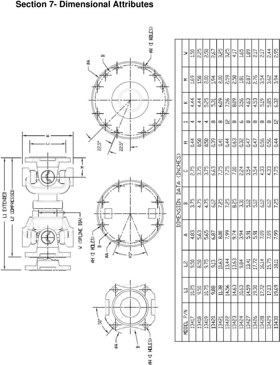
13 Section 7- Dimensional Attributes
14 Section 8 Troubleshooting Cause: 8.1 Flange Loose on Shaft 1. Set screw over keyway not tightened 2. Weight limitations exceeded for bored flanges or shaft diameter undersized. 8.2 Vibration 1. Companion flange or fastener loose. 2. Driveshaft mounting fasteners loose. 3. Flange faces not seated. 4. Flange face or pilot run-out exceeding.005 TIR. 5. Excessive radial movement at the slip yoke or binding movement. 6. Dry or brinelled (needle bearing indentations). 7. Driveshaft yokes out of phase. 8. Exceeding maximum joint acceleration. 9. Driven shaft or driver run-out. 10. Driver or driven shafts/companion flange not parallel within 1 degree. 11. Driver or driven components out of balance. 12. Operating at or near driver or driven equipment natural frequency. 13. Operation near critical or half cycle speed resonance. 14. Operation speed within a torsional vibration mode. 15. System resonance or vibration. 16. Pump noise. Solution: 1. Remove and inspect set screw. Replace if damaged. Reassemble with new or original and torque set screw. 2. Add additional set screw or replace flange with interference fit bore. 1. Remove and inspect set screw. Replace if damaged. Reassemble with new or original and torque set screw. 2. Remove and inspect fasteners, drive shaft and flange face for burs, paint and debris. Clean or de-bur face. Replace damaged fasteners. Reassemble and torque to specifications. 3. Remove driveshaft fasters. Inspect components for burs, paint and debris. Clean or de-bur face. Reassemble and torque to specification. 4. Inspect for run-out. Consult factory if out of specification. 5. Lack of adequate lubrication or overload condition. Consult factory. 6. Replace defective joints. Review and recheck the working angle of shaft. 7. Disassemble and realign yoke. 8. Reduce angle and/or reduce speed. Secure fastener and inspect for vibrations. 9. Consult with equipment manufacturer. 10. Align and adjust. Shimming structure may be necessary. 11. Consult with equipment manufacturer. 12. Consult with equipment manufacturer. 13. Consult with equipment manufacturer. Resizing of driveshaft may be required. 14. Perform torsional vibration analysis. Consult manufacturer for assistance if needed. 15. Perform torsional vibration analysis. Consult manufacturer for assistance if needed. 16. Consult with pump manufacturer. Cummins Fire Power, LLC Rev Page 12

Spicer Axles & Brakes ABIB-0302
 Information Bulletin Bulletin Type: Parts / Service Information Topic: Dana LMS Hub Assembly Procedure Steer and Drive Axles Spicer Axles & Brakes ABIB-0302 Note: Bulletin ABIB-0302 replaces the original
Pump Skid Fabrication for Magnetic Coupling. Rick Soltis Chief Mechanic City of Bedford
 Pump Skid Fabrication for Magnetic Coupling Rick Soltis Chief Mechanic City of Bedford Contents Magnetic Couplings What They Are, How They Work, Where They re Used Fabrication and Manufacturing of Pump
DiscPlus DX195 and DX225 Air Disc Brakes
 Revised 11-04 Technical Bulletin Revised 1 Technical 11-04 Bulletin DiscPlus DX195 and DX225 Air Disc Brakes Inspection, Installation and Diagnostics Air Disc Brake Inspection Intervals and Procedures
CHAPTER 65 TAIL ROTOR DRIVE SYSTEM. Section Title Page
 CHAPTER 65 TAIL ROTOR DRIVE SYSTEM Section Title Page 65-00 Description........................................ 65.1 65-10 Tail Rotor Drive Fan Shaft.............................. 65.1 65-20 Tail Rotor
SELF-STEERING AXLE TABLE OF CONTENTS
 SELF-STEERING AXLE TABLE OF CONTENTS Section 1 - Introduction Section 2 - Pre-Installation Check List Section 3 - Ride Height Adjustments Section 4 - Suspension Mount Section 5 - Axle Mount Section 6 -
Mechanical Installation
 Page -1-1. INTRODUCTION AND PURPOSE 1.1. This specification covers the installation, testing and precommissioning of mechanical equipment. Work is to be performed in conjunction with the manufacturer s
Char-Lynn Spool Valve Hydraulic Motors. Repair Information. W Series Geroler Motors
 Char-Lynn Spool Valve Hydraulic Motors Repair Information W Series Geroler Motors with Parking Brake 004 Nut Key Ring, Retaining Bearing Ring, Retaining Ring, Retaining Washer (Thick), Pressure Washer,
BoWex SD, SD1 and SD2 Operating-/Assembly Instructions
 D-807 Rheine 0111 E 1 curved-tooth gear couplings are flexible shaft connections. They are able to compensate for shaft displacement caused by, as an example, inaccuracies in production, heat expansion,
INSTALLATION INSTRUCTIONS
 Installation Instructions Ford Twin Disc Kits Serial #: Thank you for purchasing this quality ACT product. ACT has a long racing heritage supporting countless racers and series champions in many forms
BRAKE DRUM AND ROTOR SERVICE INFORMATION
 SERVICE INFORMATION To achieve maximum drum life and optimum performance, proper brake maintenance and brake balance are essential. Consult your truck or trailer manufacturer s maintenance manual for proper
ROTEX SD shiftable jaw coupling
 4014 E 1 SD shiftable jaw coupling Schutzvermerk Gezeichnet: 14.08.06 Sha Ersatz für: vom 9.07.85 4014 E SD is a torsionally flexible jaw coupling shiftable at standstill. It is able to compensate for
KIT PRESSURE PLATE FLYWHEEL DISC ALIGNMENT TOOL 600530 (F01/F03/F05) 600565 (F02/F04)* 600530 (F01/F03/F05) 600565 (F02/F04)*
 600565 (F02/F04)* 600530 (F01/F03/F05) 600565 (F02/F04)*") FORD TWIN-DISC KITS Thank you for purchasing this ACT product. ACT has a long racing heritage supporting countless racers and series champions in many forms of racing. Now you can let ACT s experience
FORD TWIN-DISC KITS Thank you for purchasing this ACT product. ACT has a long racing heritage supporting countless racers and series champions in many forms of racing. Now you can let ACT s experience
Rebuild Instructions for 70001 and 70010 Transmission
 Rebuild Instructions for 70001 and 70010 Transmission Brinn, Incorporated 1615 Tech Drive Bay City, MI 48706 Telephone 989.686.8920 Fax 989.686.6520 www.brinninc.com Notice Read all instructions before
1.8 CRANKSHAFT OIL SEALS
 SERIES 60 SERVICE MANUAL 1.8 CRANKSHAFT OIL SEALS An oil seal is fitted between each end of the crankshaft and the bores of the flywheel housing and gear case cover to retain the lubricating oil in the
Important: Please read these instructions carefully and completely before starting the installation. TITAN Fuel Tanks
 TITAN pt. no.: 03 0000 0120 Important: Please read these instructions carefully and completely before starting the installation. TITAN Fuel Tanks INSTALLATION INSTRUCTIONS G e n e r a t i o n V Extended
Q&A Session for Advanced Ball Screws 102: Troubleshooting for Design Engineers
 Q&A Session for Advanced Ball Screws 102: Troubleshooting for Design Engineers Topic: Noise Q: Is there a way to predict/calculate noise on a ball screw? A: No, there is no way to calculate the noise of
SLP 1.85 Ratio Offset Rocker Arms with Valve Springs, LS3
 PART #50190 SLP 1.85 Ratio Offset Rocker Arms with Valve Springs, LS3 PACKING LIST Before installation, use this check list to make sure all necessary parts have been included. ITEM QTY CHECK PART NUMBER
Thank You For Choosing. INSTALLATION INSTRUCTIONS Portal Gear Hubs Polaris RZR 800. (installation performed on 60 Model) (Right) (Left)
 (Right) (Left)") 740B Clifty Drive Madison, Indiana 47250 812-574-7777 INSTALLATION INSTRUCTIONS Portal Gear Hubs Polaris RZR 800 A (installation performed on 60 Model) Item Description Qty A Rotor 4 B Gear Box, L 2 C
740B Clifty Drive Madison, Indiana 47250 812-574-7777 INSTALLATION INSTRUCTIONS Portal Gear Hubs Polaris RZR 800 A (installation performed on 60 Model) Item Description Qty A Rotor 4 B Gear Box, L 2 C
FJ2. 2 Ton Trolley Floor Jack Assembly & Operating Instructions
 FJ2 2 Ton Trolley Floor Jack Assembly & Operating Instructions READ ALL INSTRUCTIONS AND WARNINGS BEFORE USING THIS PRODUCT. This manual provides important information on proper operation & maintenance.
Thank You For Choosing. INSTALLATION INSTRUCTIONS Portal Gear Hubs Polaris RZR XP 900 Crew. (Right) (Left)
 (Left)") 740B Clifty Drive Madison, Indiana 47250 812-574-7777 INSTALLATION INSTRUCTIONS Portal Gear Hubs Polaris RZR XP 900 Crew A Item Description Qty A Rotor 4 B Gear Box, L 2 C Gear Box, R 2 D Gasket 4 E Cap
740B Clifty Drive Madison, Indiana 47250 812-574-7777 INSTALLATION INSTRUCTIONS Portal Gear Hubs Polaris RZR XP 900 Crew A Item Description Qty A Rotor 4 B Gear Box, L 2 C Gear Box, R 2 D Gasket 4 E Cap
Table of Contents. Overview 1. Pump Disassembly 2. Control Disassembly / Reassembly 7. Pump Reassembly 13. Adjustment Procedures DR Control 19
 Table of Contents Overview 1 Pump Disassembly 2 Control Disassembly / Reassembly 7 Pump Reassembly 13 Adjustment Procedures DR Control 19 Adjustment Procedures DRG Control 20 Adjustment Procedures DFR
DODGE USAF 200/300 Direct Mount Pillow Block Bearings
 DODGE USAF 200/300 Direct Mount Pillow Block Bearings These instructions must be read thoroughly before installation or operation. WARNING: To ensure that drive is not unexpectedly started, turn off and
IEC Three Phase AC Motors (Aluminum Frame) Installation & Operating Manual
 Installation & Operating Manual") IEC Three Phase AC Motors (Aluminum Frame) Installation & Operating Manual 7/09 MN301 Table of Contents Section 1 General Information.................................................. 1-1 Overview........................................................
IEC Three Phase AC Motors (Aluminum Frame) Installation & Operating Manual 7/09 MN301 Table of Contents Section 1 General Information.................................................. 1-1 Overview........................................................
3097 en - 2013.06 / e. This manual is to be given to the end user POULIBLOC 2000-3000. Shaft mount reducer. Installation
 097 en - 0.06 / e 8 en This manual is to be given to the end user POULIBLOC 000-000 Installation LEOY-SOME ISTALLATIO POULIBLOC 000-000 097 en - 0.06 / e This document complements the general instructions
Rexroth Hydraulic Pump A10VO Series User Manual
 Rexroth Hydraulic Pump A10VO Series User Manual Rexroth Hydraulic pump A10VO Series User Manual Revised 5/1/2009 Page 1 of 12 Functional Purpose This pump is preferred over a fixed displacement (gear)
Field Application Note
 Field Application Note Reverse Dial Indicator Alignment RDIA Mis-alignment can be the most usual cause for unacceptable operation and high vibration levels. New facilities or new equipment installations
Repair of Hyd-ro-ac Actuators
 Repair of Hyd-ro-ac Actuators OVERHAUL INSTRUCTIONS SS-.2A-1V SS-.5A-1V SS-.5A-2V Read the entire contents of these instructions before installing the actuator and before making any connections to the
Chapter 7 Hydraulic System Troubleshooting
 Chapter 7 Hydraulic System Troubleshooting General The following troubleshooting information is provided as a general guide to identify, locate and correct problems that may be experienced with the hydraulic
Bearing Failure: Causes and Cures
 Bearing Failure: Causes and Cures bearing.ppt Page 1 Excessive loads usually cause premature fatigue. Tight fits, brinelling and improper preloading can also bring about early fatigue failure. The solution
HYDRAULIC LIFT TABLE CART 2200-LB.
 HYDRAULIC LIFT TABLE CART 2200-LB. OWNER S MANUAL WARNING: Read carefully and understand all MACHINE ADJUSTMENT AND OPERATION INSTRUCTIONS before operating. Failure to follow the safety rules and other
INSTRUCTIONS AND PARTS LIST FOR MODEL 70H & 75H HAND-OPERATED HYDRAULIC PRESS
 INSTRUCTIONS AND PARTS LIST FOR MODEL 70H & 75H HAND-OPERATED HYDRAULIC PRESS SETTING UP THE PRESS FOR OPERATION For shipping convenience, the gauge, pump handle, hoist crank, screw nose and base angles
PVM Piston Pumps Service Manual
 PVM Piston Pumps Service Manual PVM018/020 PVM045/050 PVM057/063 PVM074/081 PVM098/106 PVM131/141 Table of Contents Service Parts Pump Description... 3 Basic pump Pump Operation Controls Types Part Identification...
Slide the new steering column shaft through the steering column from the driver compartment.
 Slide the new steering column shaft through the steering column from the driver compartment. Push the column shaft through the steering column until the machined end is out past the column lower bushing.
BOWIE PUMPS OPERATION - MAINTENANCE
 BOWIE PUMPS OPERATION - MAINTENANCE PUMPING PRINCIPLE: The meshing owieeof the gears cause a slight depression, with the resulting enmeshing of the gears causing a vacuum drawing the fluid being pumped
Drive shaft, servicing
 Volkswagen Passat B6 - Drive shaft, servicing Стр. 1 из 41 40-7 Drive shaft, servicing Drive shafts, overview I - Assembly overview: Drive axle with CV joint VL100 40-7, Drive axle with CV joint VL100,
MODEL G300 BRAKE BLEEDER
 MODEL G300 BRAKE BLEEDER Installation, Operation & Repair Parts Information Branick Industries, Inc. 4245 Main Avenue P.O. Box 1937 Fargo, North Dakota 58103 REV060616 P/N: 81-0035G 1 THIS PAGE INTENTIONALLY
Unit: mm(in) Item Standard value Service limit Axle shaft run out - 0.2(0.008)
 Item Standard value Service limit Axle shaft run out - 0.2(0.008)") Rear Wheel/Brake/Suspension 13. Rear Wheel/Brake/Suspension Service Information 13-1 Troubleshooting 13-2 Rear Wheel 13-3 Rear Cushion 13-4 Rear Swing Arm 13-7 Service Information General Safety If the
Rear Wheel/Brake/Suspension 13. Rear Wheel/Brake/Suspension Service Information 13-1 Troubleshooting 13-2 Rear Wheel 13-3 Rear Cushion 13-4 Rear Swing Arm 13-7 Service Information General Safety If the
DYNA RIDER FOOTBOARD KIT
 -J0 REV. 0-0-0 DYNA RIDER FOOTBOARD KIT GENERAL Kit Number 000 Models For model fitment information, see the P&A Retail Catalog or the Parts and Accessories section of www.harley-davidson.com (English
DIAMOND Gear Company, LTD. an ERIKS Company. Installation, Maintenance, & Operation Manual Declutchable Worm Gear
 DIAMOND Gear Company, LTD. an ERIKS Company Installation, Maintenance, & Operation Manual Declutchable Worm Gear 2016 DECLUTCHABLE WORM GEAR INSTRUCTIONS This is an instructional manual which provides
Trunnion-Design Ball Valves
 Trunnion-Design Ball Valves 12" 20" (DN 300 500) Series 7150 12" (DN 300) Series 730S 12" 20" (DN 300 500) Series 7300 14" 24" (DN 350 600) Series 9150 14" 24" (DN 350 600) Series 9300 Installation, Maintenance
Table of Contents WARNING SYMBOLS AND DEFINITIONS
 Table of Contents SAFETY INSTALLATION OPERATION MAINTENANCE Safety... 2 Specifications... 4 Installation... 5 Operation... 8 WARNING SYMBOLS AND DEFINITIONS Maintenance... 9 Parts List and Assembly Diagram...
1000-LB. TRAILER JACK OWNER S MANUAL
 1000-LB. TRAILER JACK OWNER S MANUAL WARNING: Read carefully and understand all INSTRUCTIONS before operating. Failure to follow the safety rules and other basic safety precautions may result in serious
Parts Replacement Manual For DODGE TORQUE-ARM Speed Reducers Straight Bore & Taper Bushed
 Parts Replacement Manual For TORQUE-ARM Speed Reducers Straight Bore & Taper Bushed TXT815A - TXT825A SIZES: TXT915A - TXT926A TXT1015A - TXT1024A WARNING: Because of the possible danger to person(s) or
2007 Hummer H3. 2007 BRAKES Disc Brakes - H3. Fastener Tightening Specifications Specification Application
 2007 BRAKES Disc Brakes - H3 SPECIFICATIONS FASTENER TIGHTENING SPECIFICATIONS Fastener Tightening Specifications Specification Application Metric English Backing Plate Bolts 135 N.m 100 lb ft Brake Hose
Electrically Released Brake ER-825, ER-1225 with Pin Drive Armatues for Montgomery Kone
 P-230 819-0466 Electrically Released Brake ER-825, ER-1225 with Pin Drive Armatues for Montgomery Kone Installation & Operating Instructions Contents Introduction........................... 3 Installation
NEWCO VALVES Newmans Inc., Newmans Valve Ltd. NEWCO/OIC Cast Valve Operation & Maintenance Manual
 NEWCO VALVES Newmans Inc., Newmans Valve Ltd. NEWCO/OIC Cast Valve Operation & Maintenance Manual TABLE OF CONTENTS 1. Introduction and Safety Information... 1 1.1. Introduction... 1 1.2. Safety Information...
ANGLgear. right angle drives Inch and Metric Series. The Original Right Angle Gear Drive Made in the U.S.A.
 ANGLgear right angle drives Inch and Metric Series The Original Right Angle Gear Drive Made in the U.S.A. INDEX INTRODUCTION Intro to ANGLgear Inch & Metric Series pg. 2-3 2 Flange Units, Inch Series pg.
Fuel Injection Pump, Rotary (005-014)
") Fuel Injection Pump, Rotary View Related Topic Page 1 of 30 Fuel Injection Pump, Rotary (005-014) Table of Contents Summary General Information Preparatory Steps Remove Front Gear Train Rear Gear Train
Fuel Injection Pump, Rotary View Related Topic Page 1 of 30 Fuel Injection Pump, Rotary (005-014) Table of Contents Summary General Information Preparatory Steps Remove Front Gear Train Rear Gear Train
TECHNICAL SERVICE MANUAL
 TECHNICAL SERVICE MANUAL HEAVY-DUTY PUMPS SERIES 4195 AND 495 SIZES GG - AL SECTION TSM 144 PAGE 1 of 10 ISSUE D CONTENTS Introduction....................... 1 Safety Information.................... 2
cbperformance.com Please read this entire brochure prior to installing your CB Performance Products MAGNASPARK II distributor.
 - Easy -wire installation with no external spark box necessary, but can be used with one. - Precision CNC machining and hand assembled construction. This is a premium product. - Accurate super hot spark
SE-100-1, SE-200-1, SE-500-1, and SE-1000-1 AIR CHAMP PRODUCTS. User Manual SE BRAKE MODELS: (i) MTY (81) 83 54 10 18 ventas@industrialmagza.
 MTY (81) 83 54 10 18 ventas@industrialmagza.") AIR CHAMP PRODUCTS User Manual SE BRAKE MODELS: SE-00-, SE-200-, SE-500-, and SE-000- (i) FORM NO. L-20084-E-040 In accordance with Nexen s established policy of constant product improvement, the specifications
AIR CHAMP PRODUCTS User Manual SE BRAKE MODELS: SE-00-, SE-200-, SE-500-, and SE-000- (i) FORM NO. L-20084-E-040 In accordance with Nexen s established policy of constant product improvement, the specifications
SureSite Magnetic Liquid Level Indicator
 SureSite Magnetic Liquid Level Indicator Instruction Bulletin No. 177664-1 (Rev. E) Section 1: Weldments Thank you for purchasing the GEMS SureSite Magnetic Level Indicator. Please read this document prior
TITAN 13 x 2 ½ BRAKES
 INSTALLATION INSTRUCTION AND SERVICE MANUAL Actuator/Trailer Dealer - Please provide these instructions to the consumer. Consumer - Read and follow these instructions. Keep them with the trailer for future
Loewe GK Installation and operating manual
 SCHMIDT-KUPPLUNG GmbH Loewe GK Installation and operating manual Loewe GK Loewe GK: angular and radial displacement compensation combined with axial stiffness. The compact coupling combines angular and
Step-by-step instructions:
 Spark plug thread repair for Ford Triton cylinder heads Step-by-step instructions: Identification Installation Verification Specifically designed and tested for 4.6L, 5.4L, and 6.8L 2 and 4 valve heads,
White Industries Rear Hub Instructions
 White Industries Rear Hub Instructions Tool required: 2mm allen/hex wrench, 19mm socket, 20mm socket, and mallet. 1. Loosen the set screws located in the adjusting collar by using a 2mm allen wrench inserted
Johnson Power Ltd. / MAINA GEAR COUPLINGS
 PGE 1 Johnson Power Ltd. / MIN GER OUPLINGS Johnson Power, Ltd. is now pleased to offer Maina gear couplings. Maina designs and manufactures a complete line of gear couplings and spindles for industrial
Sliding Barn Door Hardware Installation Instructions BALDUR and ODEN
 Sliding Barn Door Hardware Installation Instructions BALDUR and ODEN Installation Instructions Structural Information For standard systems and most custom single door opening systems. General Overview
TITAN Fuel Tanks. INSTALLATION INSTRUCTIONS G e n e r a t i o n V
 TITAN pt. no.: 02 0000 0143 Important: Please read these instructions carefully and completely before starting the installation. TITAN Fuel Tanks INSTALLATION INSTRUCTIONS G e n e r a t i o n V Extended
PowerLine Magnetic-Laser Sheave Alignment System Instructions
 PowerLine Magnetic-Laser Sheave Alignment System Instructions The PowerLine Magnetic-Laser Sheave Alignment System laser aligns belts, pulleys, sheaves, sprockets, gear trains, rollers, platforms, conveyors,
300 SERIES 331, 332, 333, 344, 356 AND 367 MODELS
 Section: MOYNO 500 PUMPS Page: 1 of 8 Date: March 1, 1998 SERVICE MANUAL MOYNO 500 PUMPS 300 SERIES 331, 332, 333, 344, 356 AND 367 MODELS Mechanical Seal Models Packing Gland Models MODELS DESIGN FEATURES
System Saver 318 Air Compressor for Mack E-Tech and ASET Engines
 Maintenance Manual 31 System Saver 318 Air Compressor for Mack E-Tech and ASET Engines Revised 08-05 NON-THROUGH DRIVE THROUGH DRIVE Service Notes About This Manual This manual provides service and repair
Oregon Fuel Injection
 Corporate Office: P.O. Box 21121, VE Pump Removal and Installation Cummins Lock Timed Applications Removal Clean the exterior of the injection pump and mounting surfaces. 1. Disconnect the fuel return
Strut Spring Compressor
 Strut Spring Compressor Item 43753 Read this material before using this product. Failure to do so can result in serious injury. SAVE THIS MANUAL. When unpacking, make sure that the product is intact and
Tri-Homo Style Operation and Maintenance Instructions
 Tri-Homo Style Operation and Maintenance Instructions One Research Drive Stratford, CT 06615 (203) 375-0063 www.sonicmixing.com 1 Installation and Start-up Do not perform following adjustments without
Toroidal Conductivity Sensor
 Instruction Sheet PN 51A-/rev.C June 2012 Toroidal Conductivity Sensor For additional information, please visit our website at www.emersonprocess.com/rosemountanalytical.com SPECIFICATIONS Wetted Materials:
AMPSEAL* Automotive Plug Connector and Header Assembly
 AMPSEAL* Automotive Plug Connector and Header Assembly Application Specification 24 SEP 97 Rev E All dimensions are given in millimeters unless otherwise specified. All dimensional tolerances are +0.2
Float and Thermostatic Traps Series H, C and X
 Hoffman Specialty Installation & Maintenance Instructions HS-(E) and Thermostatic Traps Series H, C and X Series C & NPT Series C NPT Series X NPT Series C NPT Series H Ratings Maximum Max. Operating NPT
PTO OWNER S MANUAL ALLISON FAMILY CODE. pag.1
 PTO OWNER S MANUAL FAMILY CODE ALLISON pag.1 CONTENTS GENERAL INFORMATION Safety information...3 OMFB P.T.O. Safety Label Instructions...6 Foreword...7 INSTALLATION INSTRUCTIONS Mounting the PTO on the
S&G Model 2937 Group 1 Combination Lock
 Installation and Combination Changing Instructions S&G Model 2937 Group 1 Combination Lock NOTE: READ COMPLETE INSTRUCTIONS BEFORE INSTALLATION These instructions should be followed when installing the
6-Speed Synchromesh Transmission Service Manual. (FS-6406 Series)
") 6-Speed Synchromesh Transmission Service Manual (FS-6406 Series) Issue 01/2003 Eaton 6-Speed Synchromesh Transmission Truck Components Operations Europe PO Box 11 Worsley Manchester M28 5GJ England Service
6-Speed Synchromesh Transmission Service Manual (FS-6406 Series) Issue 01/2003 Eaton 6-Speed Synchromesh Transmission Truck Components Operations Europe PO Box 11 Worsley Manchester M28 5GJ England Service
Failure to comply with the following cautions and warnings could cause equipment damage and personal injury.
 1.0 IMPORTANT RECEIVING INSTRUCTIONS Visually inspect all components for shipping damage. Shipping Damage is not covered by warranty. If shipping damage is found, notify carrier at once. The carrier is
AZEK Rail Install Guide
 TRIM MOULDING DECK PORCH RAIL PAVERS AZEK Rail Install Guide Installing AZEK Rail with CableRail by Feeney... 1 Installing CableRail by Feeney for AZEK Rail... 7 Installing AZEK Rail Stairs with CableRail
due to uncertainty. This, in turn, has a direct impact on equipment availability and maintenance costs. Unfortunately, due to misconceptions and
 due to uncertainty. This, in turn, has a direct impact on equipment availability and maintenance costs. Unfortunately, due to misconceptions and pressure from plant operators to get "back on line", it
Hydraulic Transmission Jacks Operating Instructions & Parts Manual
 Blackhawk Automotive is a Licensed Trade Mark Made by SFA Companies, Kansas City, MO Hydraulic Transmission Jacks Operating Instructions & Parts Manual Model BH7011 BH7210 Capacity 1/2 Ton 1 Ton SFA Companies
SINGLE PHASE MOTORS. INSTALLATION AND MAINTENANCE MANUAL March 21, 2006
 SINGLE PHASE MOTORS INSTALLATION AND MAINTENANCE MANUAL March 21, 2006 Irvine, California (800) 474-0520 Indianapolis, Indiana (800) 866-7973 Hamilton, Ontario (800) 809-0330 e-mail: sales@sterlingelectric.com
Char-Lynn Hydraulic Motor. Repair Information. 10 000 Series. October, 1997
 Char-Lynn Hydraulic Motor October, 1997 Repair Information Geroler Motor Two Speed 001 27 Retainer inside bore of valve plate bearingless motors only 4 15 16 3 6 35 Parts Drawing 25 2 2 1 19 17 36 40 47
ARVINMERITOR UNITIZED FRONT WHEEL HUB INSPECTION AND MAINTENANCE
 SERVICE BULLETIN (Also applies to Mack Trucks Australia) NUMBER: SB-423-002 DATE: 8/23/02 MODEL: All with FF981 Front Axle ARVINMERITOR UNITIZED FRONT WHEEL HUB INSPECTION AND MAINTENANCE The ArvinMeritor
FIXED DISPLACEMENT HYDRAULIC VANE PUMPS BQ SERIES
 BQ FIXED DISPLACEMENT HYDRAULIC VANE PUMPS BQ SERIES Versatility, power, compactness and low running costs are the main characteristics of B&C vane pumps. All the components subject to wear are contained
HYDRAULIC TABLE CART 500-LB.
 HYDRAULIC TABLE CART 500-LB. OWNER S MANUAL WARNING: Read carefully and understand all MACHINE ADJUSTMENT AND OPERATION INSTRUCTIONS before operating. Failure to follow the safety rules and other basic
Fisher 1052 Size 20 Diaphragm Rotary Actuator with F and G Mounting Adaptation
 Instruction Manual 1052 Size 20 Actuator (F & G) Fisher 1052 Size 20 Diaphragm Rotary Actuator with F and G Mounting Adaptation Contents Introduction... 1 Scope of manual... 1 Description... 1 Specifications...
MKV Golf GTI Rear Brake Service - Replace Pads and Rotors
 Page 1 Installation Procedures MKV Golf GTI Rear Brake Service - This tutorial is provided as a courtesy by ECS Tuning. Proper service and repair procedures are vital to the safe, reliable operation of
Instructions and precautions. Fork Height. Visit our website at: http://www.harborfreight.com
 Pallet Jack Item 68760 / 68761 Instructions and precautions Specifications Capacity Control Lever Fork Height Fork Length Fork Width Maximum Minimum Width over Forks Steering Wheel Dia. 2-1/2 Ton (5,000
Char-Lynn Hydraulic Motors. Repair Information. W Series Geroler Motors 002, 003. April, 1999
 Char-Lynn Hydraulic Motors April, 1999 Repair Information W Series Geroler Motors 002, 003 W Series Geroler Motors Tools Required 5/16 inch Hex Key Bullet for Shaft Installation - Eaton Tool No. 600633
TUTORIAL. REbUILdING. REAR CALIpER O-RING CONVERSION CORVETTE 1965-82. Part #: HT-2
 Part #: HT-2 1965-82 CORVETTE O-RING CONVERSION REAR CALIpER REbUILdING TUTORIAL Choosing a Brake Caliper Rebuild Kit Standard Lip Seals vs. O-Ring Seals Lip seal design seals are used on 1965-1982 Corvette
2100 AD 015 0009 Mirror Elevator Ball Nut Replacement Procedure
 2100 AD 015 0009 Mirror Elevator Ball Nut Replacement Procedure Derek Guenther 1/28/2015 Rev. Purpose The purpose of this document is to describe the procedure necessary to replace one of the ball nuts
6001-602 NOTCHED MARKER DISCS/HUBS BOX
 6001-602 NOTCHED MARKER DISCS/HUBS BOX YETTER MANUFACTURING CO. FOUNDED 1930 Colchester, IL 62326-0358 Toll free: 800/447-5777 309/776-3222 (Fax) Website: www.yetterco.com Email: info@yetterco.com 1 6001-602
AWWA Butterfly Valve Operation and Maintenance Manual Series 511A & 510A 20 and Smaller
 January 2013 AWWA Butterfly Valve Operation and Maintenance Manual Series 511A & 510A 20 and Smaller Milliken Valve Company 190 Brodhead Avenue, Suite 100 Bethlehem, PA 18017 Phone: (610) 861-8803 Fax:
FIXED DISPLACEMENT HYDRAULIC VANE PUMPS BQ SERIES
 BQ FIXED DISPLACEMENT HYDRAULIC VANE PUMPS BQ SERIES Versatility, power, compactness and low running costs are the main characteristics of B&C vane pumps. All the components subject to wear are contained
PVH131/141 Variable Displacement Piston Pump - 11 Design
 Service Data Vickers Piston Pumps PVH131/141 Variable Displacement Piston Pump - 11 Design Revised 05/01/97 M-2209-S Maximum Adjustable Stop S Option 913341 Locknut Torque 25-50 N.m. (18-37 lb. ft.) Torque
ORTHOBLOC 3000. Drive systems. Installation. This manual is to be given to the end user. 3996 en - 2013.04 / k. R max - 5 mm.
 en - 01.0 / k 1 en This manual is to be given to the end user --> B7 (0 to 0 ) R max - mm R min + mm ORTHOBLOC 000 Installation LEROY-SOMER Ot 000 en - 01.0 / k NOTE LEROY-SOMER reserves the right to modify
FIXED DISPLACEMENT HYDRAULIC VANE PUMPS BQ SERIES
 BQ FIXED DISPLACEMENT HYDRAULIC VANE PUMPS BQ SERIES Versatility, power, compactness and low running costs are the main characteristics of B&C vane pumps. All the components subject to wear are contained
The cylinder head bolts tightening stages have been updated as listed in Table 1.
 NUMBER: 07 EPA04 MBE 4000-6 S.M. REF.: 1.2.2 ENGINE: MBE 4000 DATE: November 2007 SUBJECT: CYLINDER HEAD BOLTS TIGHTENING STAGES PUBLICATION: 6SE412 The cylinder head bolts tightening stages have been
Pump Specifications 250 Series Submersible Sump / Effluent Pump 2 Solids handling
 Pump Specifications 250 Series Submersible Sump / Effluent Pump 2 Solids handling 250_P1 R10/7/2015 Copyright 2015 Liberty Pumps Inc. All rights reserved. Specifications subject to change without notice.
NORSOK Compact Flange Installation and Assembly Procedure
 NORSOK Compact Flange Installation and Assembly Procedure Hytorc Norway www.hytorc.no P.Nødland. Page 2 INTRODUCTION Scope The following main operations are covered in this section: Assembly/disassembly
DTM04 TANK MONITOR DTM08 TANK MONITOR Dtm12 TANK MONITOR. Installation and Operation Manual
 DTM04 TANK MONITOR DTM08 TANK MONITOR Dtm12 TANK MONITOR Installation and Operation Manual 1 ENGLISH Safety Instructions 2 Features 2-3 Specifications 3 Installation 4-5 Wiring Diagrams 6-7 Warranty 8
PALLET JACK - 2.5 TON
 PALLET JACK - 2.5 TON 39939 SET UP AND OPERATING INSTRUCTIONS Visit our website at: http://www.harborfreight.com Read this material before using this product. Failure to do so can result in serious injury.
Flat Bottom Long Ram Hydraulic Jack
 Flat Bottom Long Ram Hydraulic Jack 3 Ton 8 Ton 36468 36469 ASSEMBLY & OPERATING INSTRUCTIONS 349 Mission Oaks Blvd., Camarillo, CA 930 Visit our Web site at http://www.harborfreight.com TO PREVENT SERIOUS
DeZURIK 3-20" BAW AWWA BUTTERFLY VALVES WITH TRANSFER MOLDED SEAT
 3-20" BAW AWWA BUTTERFLY VALVES WITH TRANSFER MOLDED SEAT Instruction D10386 August 2013 Instructions These instructions provide installation, operation and maintenance information for BAW Butterfly Valves.
INSTRUCTIONS AND PARTS LIST SINGLE GIRDER UNDERHUNG CRANE BRIDGE KITS 1/2 THRU 10 TON HAND GEARED AND MOTOR DRIVEN
 INSTRUCTIONS AND PARTS LIST SINGLE GIRDER UNDERHUNG CRANE BRIDGE KITS 1/2 THRU 10 TON HAND GEARED AND MOTOR DRIVEN JUNE, 1999 COPYRIGHT 1999, Columbus Mckinnon Corporation PART NO. 113533-71 Page 1 COLUMBUS