6 th Pipeline Technology Conference Abstract. Large size quarter turn control valves can improve safety in pipelines
|
|
|
- Julianna Snow
- 7 years ago
- Views:
Transcription
1 6 th Pipeline Technology Conference 2011 Abstract Large size quarter turn control valves can improve safety in pipelines Most control valve applications in pipelines are related to system start-up and shut down, emergency operations, delivery control, fluid speed control for pipeline internal examination. Selection of the right control valve is a key factor for long term successful performance for large applications where the safety and security of supply are important considerations. This document presents considerations for control valve selection to improve the safety and operation of oil and gas pipelines. Axial control valves are used when high pressure drop, high flow coefficients, low noise levels and bubble tight shut-off are required. Common applications include compressor start-up, shut-down and High Integrity Pressure Protection Systems (HIPPS). Triple offset valves (TOV) are used for large volume flow control, bubble tight shutoff, pressure drops of less than 30%.Typical applications include delivery point and controlled blow down. Ball valves are used for speed control for intelligent pig travel during pipeline examination and cleaning operations. Tyco Flow Control has researched, developed and supplied devices for a range of applications to assure the safe and reliable operation of critical control valve systems. Paper 1.Introduction to Control Valves and Fluid Flow The following factors have to be considered when performing a Cv value calculation: flow value, characteristic, choked and critical flow, and regulation ratio. Cv or Kv flow value Kv is the flow of water at 15 C in m3/h and at a pressure drop of 1 bar at constant conditions within the valve. Cv is the flow of water in gpm at 60 F and at a pressure drop of 1 psi at constant conditions within the valve. Cv: Kv

2 1.1 Characteristic according to IEC 534-2/ISA S75.01 and S Cv/Rated Cv values The flow characteristic represents the flow in relation to the opening position of the valve at constant pressure drop. 1.2 Choked and critical flow The choked and critical flow is the maximum possible flow of compressible and incompressible media through the valve at operating conditions. Choked flow is a condition that takes place in a valve when the static pressure of the liquid drops below the vapor pressure, causing the liquid to flash to a vapor. The vapor bubbles occupy more volume than the same mass of liquid, resulting in restriction of the flow through the device. When fully choked flow occurs, fluid flow through the valve will not increase when the downstream pressure decreases. Choked flow results in high noise levels, vibration, pipe stress, and erosion and pitting of the valve internals. Choked flow may result from a wrong sized control valve or if an unsuitable type of valve for that application was specified. Figure Regulation ratio Cv min/rated Cv The regulation ratio is the ratio of max. and min. flow (Cv or Kv) adjustable without any practical variation. Calculation programs according to IEC 534 are available to calculate the Cv value. The noise level is calculated according to VDMA (liquid) and IEC (gas). FL liquid pressure recovery factor is an important characteristic of a control valve, which shows the pressure recovered from the vena contracta to the valve outlet relative to the general pressure drop across the valve. The FL for butterfly and ball

3 valves, is in the range of 0.55 to 0.7,-as per in the ISA Standard S Globe valves, have a higher FL in the range of 0.85 to 0.9. Figure 2 Notes 2. Large size and High Capacity Control Valves By rule of thumb, globe-style valves larger than 12-inch, ball valves over 24-inch, and high performance butterfly valves larger than 30-inch fall in the special valve category. As valve sizes increase arithmetically, static pressure loads at shutoff increase geometrically. In consequence, unbalance forces, shaft robustness, bearing loads, and available actuator torque all become more significant with increasing valve size. Even with lowered working pressure ratings, the flow capacity of some large-flow valves remains terrific. Noise levels have to be carefully considered in all large-flow installations due to sound pressure levels increase proportionally direct to flow magnitude. To keep the noise behind tolerable threshold solutions include large cast or fabricated valve body designs, usually cage-style construction, with a great number of small flow openings through the wall of the cage, labyrinth design and axial flow nozzle design. Actuator requirements are also severe, double acting pneumatic pistons are commonly specified for large-flow applications but there are an increased trend to use spring return actuators for safety issues and ESD. The size and weight of the valve and actuator components cause difficulties during installation and maintenance procedures. Quarter turn valves are more compact that linear valve facilitating the Installation into the pipeline, removal and replacement of major trim parts. The non rising stem is preferred for fugitive emissions compliance since wetted components never go outside the pressure vessel Closed to open transients are critical in large size valves not exclusive of control valve, even for on-off applications have to be considered and studied
4 . Figure TOV in pipeline controls Application TOV are typically utilized in suction line, turbine trip, delivery lines in oil, gas light hydrocarbons and water applications. Due to the valve design, incorporating a small face-to-face dimension and lower weight than most valve types, the TOV is an economical choice for larger line sizes (i.e. 12" and above). Additional advantages of this valve are standard face-to-face dimensions, relatively high coefficient of flow (Cv), zero leakage metal to metal seat inherently fire safe, non-rubbing (frictionless) 90 degrees rotation, which minimize hysteresis and dead band, wear of sealing elements even during heavy duty modulating services, and to achieve high speed of operation for emergency
5 shutdown applications (ESD), thus combining in one valve control and isolation (ESD) capabilities. The same as the ball valve, the TOV complies with ASME pressure ratings and face-to-face dimensions. This enables the valve to be easily retrofitted inline regardless of the manufacturer. In addition, the small face-to-face dimension facilitates piping design. The ASME pressure classes adhered to by most manufacturers include up to class #1500 allowing a maximum pressure of 250 bar. The TOV is considered a high recovery valve, since only the disc obstructs the valve flow path. The Cv is comparatively high; the pressure drop across the valve is relatively low. Hence the pump size is minimized and system wear reduced compared to that of low recovery valves. Figure 4 The characteristic values and the Cv values may differ slightly depending on the flow direction. By selecting the most suitable direction of installation and by means of an appropriate actuator selection it is possible to configure the product to assist protective functions. Figure 5 shows some pictures resulting from post-processing of a CFD analysis.

 Figure 6 The valves have to be sized to operate between 30% to 70% of travel, obtaining an optimal")
6 Figure 5 Disadvantages of the TOV are inability to handle slurry applications. As with ball valves, the cavities and leak paths around the disc stem where the stem attaches to the body are potential entrapments for fluids and slurries. The result is unwanted increased operating torque in slurry services, loose of seat tightness and erosion. Conceptually the TOV has similar sealing effect that globe plug valve (Figure 6) Figure 6 The valves have to be sized to operate between 30% to 70% of travel, obtaining an optimal control response and avoiding the cavitation zone and high noise. Cavitation can be prevented through: Use of an orifice flange Two TOV in series Reduce Δp by considering another spot of installation


7 2.1.1 TOV in transmission application Empowering the features of TOV, this application at the pipeline head or end shows the advantage of right selection after several options evaluation, obtaining the required control performance, low weight, tight shut-off and the best cost position. A delivery point supply natural gas at 80 bar, two main consumers require at maximum 60 bar in lines of 16 and 24 #600 (Figure 8 and 9) Large size globe valves, segmented ball valves, and TOV were evaluated. Since the supplier assured that the gas wells never provide more than 80 bar, the sizing exercise results indicate that the TOV will work between 30% to 70% travel in the optimal control zone, avoiding the high noise region. Extra overpressure protection is provided with additional ESD valves and HIPPS Figure 7 Figure Pipeline Ball Valves (API6D) Readily available in a variety of configurations, 3-piece, side entry (Figure10), top entry (Figure 11) and fully welded, these valves range from commodity type valves to high performance valves. Advantages of ball valves include ease of operation, standard face-to-face dimensions, high flow capacity, and high pressure/temperature capabilities. The quarter turn operation is desirable to most operators and fairly easy to automate
8 and the added feature is to be Bi-stable, even without actuators remain open or close under pressure without the need of locking devices. Figure 9 Figure 10 Ball valves, available in reduced port and full port designs are considered high recovery valves, meaning a low pressure drop and relatively high Cv. The benefits of these desirable flow parameters are reduced pump size and less system wear due to lower velocity. Ball valves act primarily as isolation valves only, although they have certain capability to throttle flow. On the other hand, exists ball valve designs specifically for throttling service including divided or split flow passages and V shaped ports. Many ball valves have a reduced bore with a Venturi-shaped flow passage. Ball valves are used in applications where a full-bore valve is needed. Ball valves operate by rotating a ball with a through-bore a quarter turn from full open to full closed. This makes for a very quick acting closure. The flow-control characteristic arises from two circle ports moving across a circular seat and from having double pressure drop across the two seats. Ball valves are normally bi-directional and have the same pressure drop as an equal length of straight pipe.
9 Pipeline ball valves are trunnion-mounted design that has the ball supported on a bearing trunnion. The differential pressure load is carried by the trunnion, thereby reducing the operating torque of the valve. Due to low friction forces, ball valves have been known to open gradually after a long exposure to vibration. Ball valves feature, together with the through conduit gate valves, the highest flow coefficient Cv values. Of course, a full bore valve has a higher Cv value than the reduced bore of the same DN. Moreover a FB valve provides a higher Cv value than the RB valve of the one step larger DN valve (for the same ball bore). That s due to the flow restriction creating turbulences and producing pressure loss. Throttling applications - When spherical valves are used in throttling applications, high velocity flow can impinge against a focused area of the ball and seals, making premature deterioration of the seating material. Special checking of working conditions or modifications to the standard design are required for ball valves to be used for throttling, including the use of metal seats, hard coatings, different speed of actuator travel and, sometimes, modifications to the ball, to give a characterized flow pattern. Figure 11 Figure 12 shows different type of seat from right to left: thermoplastic seat, elastomeric seat, metal seat. High pressure drops are not driven well due to the ball causing high velocity jets of fluid directed into the seat and body inducing erosion. Wrong selection will impact in the control performance and in the sealing tightness. Ball valves physically have a good control characteristic and give high turndown of 100:1 for standard ball valves and up to 500:1 for V ported valves (not pipeline valves). High pressure valves are available to ANSI 2500# and higher.sizes range reach up to 72
10 Metal seats, hardened surfaces are selected to work with high temperatures or/and abrasive fluids. Full ball valves are not recommended for slurries due to the solids settling out in the body cavity. Slurries tend to solidify or clog inside the cavities, greatly increasing the operating torque of the valve and in some cases rendering the valve inoperable. Therefore, most manufacturers do not recommend exceeding trace amounts of solids of more of 3%. Figure 13 shows a conceptual simplified Ball valve CV charactheristic Figure 12
11 Figure 13 Figure 14 shows the CV value and Torque as % of break torque over valve travel for a ball valve of 24, the control zone is limited and for a large size valve the effects of choke flow and temporary cavitation is reflected by the overtorque during the first 20% of travel. The pressure and velocity profile inside the valve structure is shown in Figure15 CFD calculations are required to predict the performance of the valve under throttling applications and transient in on-off service, unexpected high flow speed could potentially damage the seat.
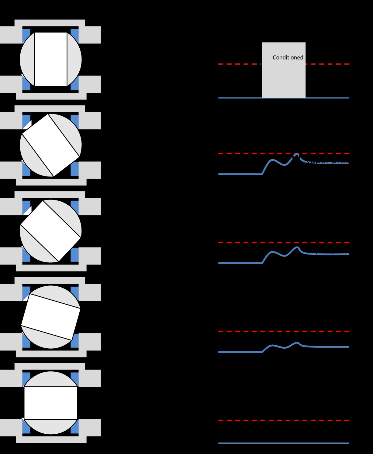
12 Figure 14
13 In the tight shut-off operation, the maximum allowable fluid velocities should not be exceeded, the recommended maximum fluid velocities are: Table 1 Liquids Gas/Steam DN m/s DN m/s <50 12 < >400 3 > Ball valves features useful for control service under well delimited conditions. The valve has to be sized to operate between 30% to 80% of travel, obtaining good control response and avoiding the cavitation zone and high noise. It is recommended a short travel time below 30% of the stroke, avoiding to remain in this zone for long time, specially in elastomeric and thermoplastic seated valves. By the use of FEA and CFD software, CV s over the stroke could be accurately calculated, avoiding the ancient mistakes of modeling simplification and obtaining transient analysis. Figure 16 shows FEA for a high pressure top entry ball valve. Figure 15 Figure 17 shows through a graphic method the deviation radius by 2D two circumference modeling vs. spatial modeling

14 Figure 16 Ball valves also feature: - good rangeability - high flow rate with low pressure drop - high Cv values - good pressure recovery That makes ball valves suitable for control service with high flow rate at low pressure drop, like for instance tank level control. Due to the high pressure recovery capability, the ball valves are susceptible to cavitation at low load for liquids or choked flow at sound velocity in gases. Care must be taken when using a ball valve on control service, to correctly size the valve to recognized standards IEC / EN Standard API6D ball valve in throttling application An application of API6D ball valves is the speed control for intelligent pigs.

15 In order to obtain detailed data of pipeline status, these devices run a lower speed than the pipeline design, in existent pipelines appears the need of regulate the flow to obtains speeds of 3m/S to 5m/s Figure 17 Figure 18 shows typical pig trap installation. The pig must fit loosely in the launcher/receiver so the barrel of the launcher/receiver must have a greater diameter than the pipe itself. When the pig is received the fluid has to pass around the pig in the barrel, so it is a good design rule to give the barrel a cross sectional area of almost double that of the linepipe. The barrel have to e sized considering that the flow velocity around the pig is less than 20m/s when flowing gas and 4m/s when flowing liquid. The launcher/receiver must have an isolation valve between the barrel and the pipeline. That valve is a full bore valve to allow the pig to pass unrestricted into or out of the barrel. It is very important that this valve have high quality sealing. It must be either a soft seated ball valve or a ball valve with metal to metal seating. This valve is the only existent barrier between the line contents and the operator when the closure is open, the barrel must have a good drain valve if it is a liquid system, or a good vent valve if it is a gas system. Both are required to depressurize the barrel before opening it. A bypass line is required around the barrel isolation valve. This is called the kicker line. It generally tees off from the branch line from the main tee and connects to the launcher or receiver barrel. The kicker must have at least one isolation valve with the same excellent isolation capabilities as the barrel isolation valve for the same reasons as the barrel isolation valve. It is generally sized for a maximum flow velocity of 4m/s for liquid and 20m/s for gas. The kicker line valve is used to throttle the flow from full pipeline pressure to zero pressure. This valve (or a valve array) is used not only for isolation but also throttling temporary.

16 2.2.2 Application of control valve in centrifugal compressor system Typical pipeline applications are Anti-surge / recycle control, discharge control (Figure 19). To protect expensive aero-derivative compressor equipment from operating in surge, many pipeline companies will have both a surge line and a surge control line for their compressors. When compressor operation passes the surge line the compressor is shut down to avoid equipment damage. When compressor operation crosses the surge control line, the unit/station recycle valves open to increase the unit/station flow. When compressor operation crosses the surge control line, the unit/station recycle valves open to increase the unit /station flow Figure 18 The surge control valve must provide accurate control, wide flow rangeability, and quick action; this control valve is critical to the protection of the centrifugal compressor. Typical requirements are: High flow capacity with minimum pressure differential Low flow controllability Wide flow rangeability Quick stroking times of less of a second Controlled noise Valves required for this service exceed the performance of standard ball valves Some solutions in quarter turn devices are segmented ball valves, caged trims and axial flow control valves.

17 2.2.3 Segmented ball Liquid cavitation and aerodynamic noise concerns can be solved employing the principles of dividing the pressure drop into a series of small pressure drops and of separating the flow stream into many small jet streams. The use of these principles combined with the rotation of the attenuator elements provides a combination of cavitation/noise abatement with good rangeability, high capacity and certain capability to handle fluids with particle content Figure 19 Figure 20 shows the effects and benefits in pressure and velocity profile smoothing them. 2.3 Plug valve The plug valve has the same considerations as the ball valve. It born as top entry /bottom entry valve that allows in line maintenance. The pass through area modeling is relatively simpler than ball valve. The sealing contact surface design doesn t allows seal tightness across the time. 2.4 Axial Flow Control Valve Axial valve design gives the fluid symmetrical flow path charactheristics without any disturbance preventing erosion and abrasion due to this process downtime and maintenance costs are reduced.
18 Figures 20 The intrinsic capacity of the axial valve is high compared to the conventional globe control valve and enables selection of smaller valve size. Simultaneously the higher capacity can be used to minimize pressure loss or to provide for stringent control features. Figure 21 The design allows the highest efficiency for almost any applications High flow coefficient High pressure drop Low noise levels Reduced maintenance Compact Design Very low operating torques
19 Axial design allows the pressure balanced of the piston from closed to open position, resulting in the use of smaller actuators than conventional control valves and reduced stroking time making it capable of HIPPS applications. The sizing of this type of control valve is made by computerized sizing software, including FEA and CFD analysis, which selects the best solution technical and economical- to suit the application request and to give a full guarantee for the performance after installation regarding noise generation, flow capacity and cavitation.the axial design and the use of suitable gages give to this type of valve higher pressure recovery coefficients than the conventional control valves. These high coefficients reduce the possibility of cavitation. The valve body provides dramatic weight reduction compared to globe valves. This feature is even more striking combined with quarter-turn spring-return actuators. 3. Conclusions The right selection of control valve improve the safety of installation. There is nothing definitive about selecting a type of valve. Valve replacements, failures, repairs, downtime and lost product can be significantly minimized by selecting the right valve. Evaluate your system criteria relative to each valve type. Utilize the expertise of a consultant or the factory expert. Utilize valve selection software programs provided by various serious valve manufacturers. Consider the opening- closing transient time Balance controllability, rangeability, maintenance issues and seat tightness when select the valve type. Having good knowledge and well delimited conditions allows the use of standard valves and piggable isolation valves for limited amount of time or temporary control applications. Classification/Tags Pipeline and Facilities Integrity, Pipeline Components, Compressor and Pumps Stations Flow Control, HIPPS, Valves, Actuators, Safety
Control ball valves for severe services. Author: Michele Ferrante, PARCOL S.p.A., Italy
 Control ball valves for severe services Author: Michele Ferrante, PARCOL S.p.A., Italy Control valves are primarily classified according to the type of their obturator motion which can be linear or rotary.
www.klmtechgroup.com TABLE OF CONTENT
 Page : 1 of 31 Project Engineering Standard www.klmtechgroup.com KLM Technology #03-12 Block Aronia, Jalan Sri Perkasa 2 Taman Tampoi Utama 81200 Johor Bahru Malaysia TABLE OF CONTENT SCOPE 2 REFERENCES
GS-General Service Control Valves
 GS-General Service Control Valves GS-General Service Valves The GS-General Service Valves continue Copes-Vulcan s tradition of designing and manufacturing control valves that provide both exceptional service
VAL-MATIC VALVE AND MANUFACTURING CORP. 905 RIVERSIDE DRIVE, ELMHURST, IL 60126 TEL. (630) 941-7600 FAX.
 941-7600 FAX.") Cavitation in Valves VAL-MATIC VALVE AND MANUFACTURING CORP. 905 RIVERSIDE DRIVE, ELMHURST, IL 60126 TEL. (630) 941-7600 FAX. (630) 941-8042 www.valmatic.com CAVITATION IN VALVES INTRODUCTION Cavitation
Cavitation in Valves VAL-MATIC VALVE AND MANUFACTURING CORP. 905 RIVERSIDE DRIVE, ELMHURST, IL 60126 TEL. (630) 941-7600 FAX. (630) 941-8042 www.valmatic.com CAVITATION IN VALVES INTRODUCTION Cavitation
CCI 100 DPC DRAG Wellhead Production Choke Valve
 CCI 100 DPC DRAG Wellhead Production Choke Valve 2 Severe service DRAG choke valve delivers precise wellhead pressure control with superior reliability and life. Improves well production time Enhances
Chokes. Types Reasons Basics of Operations Application
 Chokes Types Reasons Basics of Operations Application Most Common Chokes Positive: Fixed orifice Disassemble to change bean Adjustable Provides variable orifice size through external adjustment Schematic
100DHP TM CCI DRAG Control Valve For High Pressure Turbine Bypass
 100DHP TM CCI DRAG Control Valve For High Pressure Turbine Bypass 2 What is a HP Turbine Bypass Valve? It routes high pressure, high temperature steam around the HP Turbine, from the main steam line typically
OPERATING and MAINTENANCE MANUAL SERIES 2700A CONTROL VALVE CONTENTS. INTRODUCTION...1 Scope...1 Description...1 Valve Identification...
 OPERATING and MAINTENANCE MANUAL SERIES 2700A CONTROL VALVE CONTENTS INTRODUCTION...1 Scope...1 Description...1 Valve Identification...2 1.0 VALVE INSTALLATION...2 2.0 VALVE MAINTENANCE...3 Actuator Disassembly...3
APPENDIX A CONTROL VALVE TESTING PROCEDURES AND EQUATIONS FOR LIQUID FLOWS
 APPENDIX A CONTROL VALVE TESTING PROCEDURES AND EQUATIONS FOR LIQUID FLOWS Section A.1. Flow Coefficients Definition The flow coefficient or pressure loss coefficient is used to relate the pressure loss
Select the Right Relief Valve - Part 1 Saeid Rahimi
 Select the Right Relief Valve - Part 1 Saeid Rahimi 8-Apr-01 Introduction Selecting a proper type of relief valve is an essential part of an overpressure protection system design. The selection process
Flashing and Cavitation
 As seen in the Summer 2015 issue of MAGAZINE BACK TO BASICS A high-power boiler burner in a co-generation plant Flashing and Cavitation Some of the following questions may seem unrelated, but they all
TYPE E Main Valve Sizes 3 /8 through 12
 SD 3001F PRINTED IN U.S.A. SD 3001F/0707 A B TYPE E MAIN VALVE C D E TYPE E Main Valve Sizes 3 /8 through 12 The Spence Type E Main Valve is of normally closed, single seat design featuring packless construction,
C. starting positive displacement pumps with the discharge valve closed.
 KNOWLEDGE: K1.04 [3.4/3.6] P78 The possibility of water hammer in a liquid system is minimized by... A. maintaining temperature above the saturation temperature. B. starting centrifugal pumps with the
Frequently Asked Questions
 Frequently Asked Questions System and Valve Basics: 1. Q: What is good cooling coil performance? A: The temperature range is controlled within +/- 0.5 F (0.28 C) off the cooling coil at set point or below.
Fisher CV500 Rotary Globe Control Valve
 CV500 Valve D101606012 Product Bulletin Fisher CV500 Rotary Globe Control Valve The Fisher CV500 Cam Vee-Ball control valve combines the rangeability of the cammed-segmented V-notched ball, with the inherent
CFD Analysis of a butterfly valve in a compressible fluid
 CFD Analysis of a butterfly valve in a compressible fluid 1 G.TAMIZHARASI, 2 S.KATHIRESAN 1 Assistant Professor,Professor,Departmentment of Electronics and Instrumentation,Bharath university, chennai.
Heating Water by Direct Steam Injection
 Heating Water by Direct Steam Injection Producing hot water by direct steam injection provides a solution where large volumes of hot water at precise temperatures are required, and where energy and space
Pressure Locking & Thermal Binding In Wedge Gate & Parallel Slide Gate Valves
 Pressure Locking & Thermal Binding In Wedge Gate & Parallel Slide Gate Valves CRANE Energy Flow Solutions TM Donald H. Johnson Crane Energy Flow Solutions 1 Crane Co. Resolution Made By Richard Teller
Mustang Series PRESSURE REDUCING CONTROL VALVE WITH PRESSURE SUSTAINING FEATURE. M115-2 (Globe) M1115-2 (Angle) Schematic. Standard Components
 M1115-2 (Angle) Schematic. Standard Components") Schematic Throttles to reduce high upstream pressure to constant lower downstream pressure Throttles to maintain minimum upstream pressure PRESSURE REDUCING CONTROL VALVE WITH PRESSURE SUSTAINING FEATURE
Schematic Throttles to reduce high upstream pressure to constant lower downstream pressure Throttles to maintain minimum upstream pressure PRESSURE REDUCING CONTROL VALVE WITH PRESSURE SUSTAINING FEATURE
Chapter 10. Flow Rate. Flow Rate. Flow Measurements. The velocity of the flow is described at any
 Chapter 10 Flow Measurements Material from Theory and Design for Mechanical Measurements; Figliola, Third Edition Flow Rate Flow rate can be expressed in terms of volume flow rate (volume/time) or mass
DOUBLE BLOCK AND BLEED VALVES
 DOUBLE BLOCK AND BLEED VALVES ENGINEERING - QUALITY AND TESTING Energy Valves is specialized in designing and manufacturing DBB valves (ball - plug - gate). Technical solutions and engineering are in accordance
Minor losses include head losses through/past hydrants, couplers, valves,
 Lecture 10 Minor Losses & Pressure Requirements I. Minor Losses Minor (or fitting, or local ) hydraulic losses along pipes can often be estimated as a function of the velocity head of the water within
LEAKAGE ACCEPTANCE RATES COMPARISON METAL & SOFT SEATED VALVES API 598/API 6D/MSS SP-61/FCI 70-2
 ADELAIDE BRISBANE PERTH LEAKAGE ACCEPTANCE RATES COMPARISON METAL & SOFT SEATED VALVES API 598/API 6D/MSS SP61/FCI TESTING & LEAKAGE RATES OVERVIEW From an engineering point of view, almost all valves
PRESSURE REDUCING CONTROL VALVE
 Schematics Throttles to reduce high upstream pressure to constant lower downstream pressure Low Flow By-Pass controls at low flows 4 PRESSURE REDUCING CONTROL VALVE with LOW FLOW BY-PASS FEATURE Main Line
CENTRIFUGAL PUMP SELECTION, SIZING, AND INTERPRETATION OF PERFORMANCE CURVES
 CENTRIFUGAL PUMP SELECTION, SIZING, AND INTERPRETATION OF PERFORMANCE CURVES 4.0 PUMP CLASSES Pumps may be classified in two general types, dynamic and positive displacement. Positive displacement pumps
PBX Series Quick Fit Connector Bimetallic Steam Traps
 6262100/6 IM-P626-01 ST Issue 6 PBX Series Quick Fit Connector Bimetallic Steam Traps Installation and Maintenance Instructions 1. Safety information 2. General product information 3. Installation 4. Commissioning
61W - Wafer style resilient seated butterfly valve 61L - Lugged style resilient seated butterfly valve
 61W - Wafer style resilient seated butterfly valve 61L - Lugged style resilient seated butterfly valve Features Rounded polished disc edge gives full concentric sealing, lower torques, longer seat life
Flowserve - Edward Valves Development of the Flowserve Edward Equiwedge Gate Valve
 Flowserve - Edward Valves Development of the Flowserve Edward Equiwedge Gate Valve Problem Gate valves in severe service applications that experience premature trim wear from seat guided discs or leakage
VAD. Variable Area Desuperheaters
 Desuperheater overview Steam used in process plants can be superheated, that is, heated to a temperature above saturation. The excess of temperature above its saturation is called 'superheat'. Desuperheated
DARTMOUTH COLLEGE DESIGN January 3, 2012 & CONSTRUCTION GUIDELINES
 SECTION 15062 STEAM AND CONDENSATE PIPING PART 1 DESIGN DIRECTIVES 1.1 QUALITY ASSURANCE A. Comply with the provisions of the following: 1.2 DESIGN CRITERIA 1. ASME B 31.9 Building Services Piping : for
Flanged and Butt-= Weld Type
 Document : PG00 Year : 09 Product Group 00 Flanged and Butt-= Weld Type (LNG and LPG) Page 09 Document : PG00 Year : 09 Product Group 00 Cryogenic Butterfly valves The Cryogenic Butterfly Valve Design
TOPIC: 191004 KNOWLEDGE: K1.01 [3.3/3.5] Which one of the following contains indications of cavitation in an operating centrifugal pump?
![TOPIC: 191004 KNOWLEDGE: K1.01 [3.3/3.5] Which one of the following contains indications of cavitation in an operating centrifugal pump?](/thumbs/17/105210.jpg "TOPIC: 191004 KNOWLEDGE: K1.01 [3.3/3.5] Which one of the following contains indications of cavitation in an operating centrifugal pump?") KNOWLEDGE: K1.01 [3.3/3.5] P21 Which one of the following contains indications of cavitation in an operating centrifugal pump? A. Low flow rate with low discharge pressure. B. Low flow rate with high discharge
KNOWLEDGE: K1.01 [3.3/3.5] P21 Which one of the following contains indications of cavitation in an operating centrifugal pump? A. Low flow rate with low discharge pressure. B. Low flow rate with high discharge
Why and How we Use Capacity Control
 Why and How we Use Capacity Control On refrigeration and air conditioning applications where the load may vary over a wide range, due to lighting, occupancy, product loading, ambient weather variations,
A descriptive definition of valve actuators
 A descriptive definition of valve actuators Abstract A valve actuator is any device that utilizes a source of power to operate a valve. This source of power can be a human being working a manual gearbox
Daniel. Liquid Control Valves Technical Guide. Technical Guide DAN-LIQ-TG-44-rev0813. DAN-LIQ-TG-44-rev0208. February 2008.
 DAN-LIQ-TG-44-rev0208 February 2008 Daniel Liquid Control Valves Technical Guide www.daniel.com Daniel Measurement and Control Theory, Principle of Operation and Applications This brochure has been prepared
Unit 24: Applications of Pneumatics and Hydraulics
 Unit 24: Applications of Pneumatics and Hydraulics Unit code: J/601/1496 QCF level: 4 Credit value: 15 OUTCOME 2 TUTORIAL 2 HYDRAULIC AND PNEUMATIC CYLINDERS The material needed for outcome 2 is very extensive
Severe Service Equipment
 Severe Service Equipment Introduction Pressure/Velocity Profiles in Globe Valves As a fluid travels through a conventional single-seated globe-style control valve, a vena contracta (point of narrowest
APCO SLOW CLOSING AIR/VACUUM VALVES
 BULLETIN 1 JULY 01 APCO SLOW CLOSING AIR/VACUUM VALVES Series 1900 APCO Slow Closing Air/Vacuum s Maximum Air Flow Velocity in Good Pipeline Design The Air/Vacuum operates in the normal fashion allowing
Mechanical Seal Piping Plans
 Mechanical Seal Piping Plans Single Seals plans 01, 02, 03, 11, 13, 14, 21, 23, 31, 32, 41 Dual Seals plans 52, 53A, 53B, 53C, 54, 55 Quench Seals plans 62, 65A, 65B, 66A, 66B Gas Seals plans 72, 74, 75,
BERMAD Waterworks. Pressure Relief/Sustaining Valve. 700 Series. Model 730. Features and Benefits. Major Additional Features
 Pressure Relief/Sustaining Valve Prioritizing pressure zones Ensuring controlled pipeline fill-up Preventing pipeline emptying Pump overload & cavitation protection Safeguarding pump minimum flow Excessive
BSM MOTOR DRIVEN CENTRIFUGAL PUMPS
 PRINCIPLE OF OPERATION A hydraulically and dynamically balanced impeller with raised vane sections discharges liquid as a result of the centrifugal force developed in rotation. The head developed is entirely
Air Eliminators and Combination Air Eliminators Strainers
 Description Air Eliminators and Combination Air Eliminator Strainers are designed to provide separation, elimination and prevention of air in piping systems for a variety of installations and conditions.
DEVELOPMENT OF A TWIN SCREW EXPRESSOR AS A THROTTLE VALVE REPLACEMENT FOR WATER-COOLED CHILLERS
 DEVELOPMENT OF A TWIN SCREW EXPRESSOR AS A THROTTLE VALVE REPLACEMENT FOR WATER-COOLED CHILLERS J J Brasz, Carrier Corporation, Syracuse, NY, 13221, USA joost.j.brasz@carrier.utc.com I K Smith and N Stosic
FIXED DISPLACEMENT HYDRAULIC VANE PUMPS BQ SERIES
 BQ FIXED DISPLACEMENT HYDRAULIC VANE PUMPS BQ SERIES Versatility, power, compactness and low running costs are the main characteristics of B&C vane pumps. All the components subject to wear are contained
FIXED DISPLACEMENT HYDRAULIC VANE PUMPS BQ SERIES
 BQ FIXED DISPLACEMENT HYDRAULIC VANE PUMPS BQ SERIES Versatility, power, compactness and low running costs are the main characteristics of B&C vane pumps. All the components subject to wear are contained
BALL VALVES SIDE ENTRY TOP ENTRY
 SIDE ENTRY TOP ENTRY Quality System AST S.p.A. applies efficient and useful policies aimed at ensuring the quality of the products. The high quality level system implemented within the Company ensures
BOWIE PUMPS OPERATION - MAINTENANCE
 BOWIE PUMPS OPERATION - MAINTENANCE PUMPING PRINCIPLE: The meshing owieeof the gears cause a slight depression, with the resulting enmeshing of the gears causing a vacuum drawing the fluid being pumped
Flowserve - Edward Valves Quick Closing Isolation Valves -The Equiwedge Alternative
 Flowserve - Edward Valves Quick Closing Isolation Valves -The Equiwedge Alternative Problem Fast isolation of a large bore main steam or feedwater line during a pipe rupture that seals flow in both directions.
FIXED DISPLACEMENT HYDRAULIC VANE PUMPS BQ SERIES
 BQ FIXED DISPLACEMENT HYDRAULIC VANE PUMPS BQ SERIES Versatility, power, compactness and low running costs are the main characteristics of B&C vane pumps. All the components subject to wear are contained
Section Vb2: Butterfly Valves
 Valve and Actuator Manual 977 Valve Basics and Sizing Information Section Engineering Data Book Vb2 Issue Date 0496 Section Vb2: Butterfly Valves Introduction Page 3 Advantages of Butterfly Valves 3 Disadvantages
Chapter 7 Hydraulic System Troubleshooting
 Chapter 7 Hydraulic System Troubleshooting General The following troubleshooting information is provided as a general guide to identify, locate and correct problems that may be experienced with the hydraulic
Basic Hydraulics and Pneumatics
 Basic Hydraulics and Pneumatics Module 1: Introduction to Pneumatics PREPARED BY IAT Curriculum Unit March 2011 Institute of Applied Technology, 2011 ATM 1122 Basic Hydraulics and Pneumatics Module 1:
The Axial Flow Valve. Class 300/600. sales@elster-instromet.co.uk www.elster-instromet.com SERIES
 The Axial Flow Valve SERIES Class 300/600 sales@elster-instromet.co.uk www.elster-instromet.com THE AXIAL FLOW VALVE - SERIES 300/600 A UNIQUE REGULATOR What is the Axial Flow Valve? The Axial Flow Valve
Pumps: Convert mechanical energy (often developed from electrical source) into hydraulic energy (position, pressure and kinetic energy).
 into hydraulic energy (position, pressure and kinetic energy).") HYDRAULIC MACHINES Used to convert between hydraulic and mechanical energies. Pumps: Convert mechanical energy (often developed from electrical source) into hydraulic energy (position, pressure and kinetic
HYDRAULIC MACHINES Used to convert between hydraulic and mechanical energies. Pumps: Convert mechanical energy (often developed from electrical source) into hydraulic energy (position, pressure and kinetic
Self-operated Temperature Regulators Type 1 to Type 9. PN 16 to 40 Class 125 to 300 DN 15 to 250 NPS ½ to 10 G ½ to 1 Up to 350 C Up to 660 F
 Self-operated Temperature Regulators Type 1 to Type 9 PN 16 to 40 Class 125 to 300 DN 15 to 250 NPS ½ to 10 G ½ to 1 Up to 350 C Up to 660 F Edition April 2012 Information Sheet T 2010 EN Self-operated
*Rated to 207 Bar/3000 PSI with Aluminum Body. Catalog HY15-3501/US SERIES CAVITY DESCRIPTION FLOW PRESSURE PAGE NO.
 Bodies & Contents SERIES CAVITY DESCRIPTION FLOW PRESSURE PAGE NO. /GPM BAR/PSI STANDARD CHECKS D1A6... 2U... Valve Insert, Ball Type...145/38... 42/6... 5 D1B125... 2C... Valve Insert, Ball Type... 5/132...
Self-contained valve functions as integral check valve, flow sensing element and bypass control valve.
 Self-contained valve functions as integral check valve, flow sensing element and bypass control valve. Features Eliminates high cost of installation and maintenance of complex conventional flow control
RMF Engineering 23 05 23
 PART 1 - GENERAL 1.1 RELATED DOCUMENTS A. Drawings and general provisions of the Contract, including General and Supplementary Conditions and Division 01 Specification Sections, apply to this Section.
Application of the Orifice Meter for Accurate Gas Flow Measurement page 1. Application of the Orifice Meter for Accurate Gas Flow Measurement.
 Application of the Orifice Meter for Accurate Gas Flow Measurement page 1 DANIEL MEASUREMENT AND CONTROL WHITE PAPER Application of the Orifice Meter for Accurate Gas Flow Measurement www.daniel.com Summary
BALL VALVES TECHNICAL CATALOGUE
 SITINDUSTRIE VALVO VALVES BALL VALVES Ed. 01/NOV-2004 SITINDUSTRIE reserves the right to change, without notice, 1/16 SITINDUSTRIE VALVE DIVISION We are pleased to introduce you to the ball valves manufactured
COUNTERBALANCE VALVES
 COUNTERBALANCE VALVES Introduction They are modulating valves which allow free flow into the actuator and then block the reverse flow until they feel a pilot pressure inversely proportional to the load
Pneumatic Control and Shut-off Butterfly Valve Pfeiffer Type BR 14b/31a and Type BR 14c/31a
 Pneumatic Control and Shut-off Butterfly Valve Pfeiffer Type BR 14b/31a and Type BR 14c/31a Application Tight-closing, double eccentric butterfly valve for process engineering and plants with industrial
Chapter 19 Purging Air from Piping and Vessels in Hydrocarbon Service
 BP Lower 48 Onshore Operations Safety Manual Page 4.19 1 Chapter 19 Purging Air from Piping and Vessels in Hydrocarbon Service I. General Requirements A. After motor vehicle accidents and underground excavation
CENTRIFUGAL PUMP OVERVIEW Presented by Matt Prosoli Of Pumps Plus Inc.
 CENTRIFUGAL PUMP OVERVIEW Presented by Matt Prosoli Of Pumps Plus Inc. 1 Centrifugal Pump- Definition Centrifugal Pump can be defined as a mechanical device used to transfer liquid of various types. As
Unit 24: Applications of Pneumatics and Hydraulics
 Unit 24: Applications of Pneumatics and Hydraulics Unit code: J/601/1496 QCF level: 4 Credit value: 15 OUTCOME 2 TUTORIAL 1 HYDRAULIC PUMPS The material needed for outcome 2 is very extensive so there
FLANGED END BALL VALVE
 Specification: FLANGED END BALL VALVE - Chem Oil s two-piece ball valve has been designed to handle extreme service applications with unsurpassed reliability. Valve body machined from solid wrought material
DeZURIK 3" (75MM) & LARGER ECCENTRIC PLUG VALVES
 & LARGER ECCENTRIC PLUG VALVES") BULLETIN 12.00-1C SUPERSEDES 12.00-1C & 12.60-1A JUNE 2014 DeZURIK 3" (75MM) & LARGER ECCENTRIC PLUG VALVES www.dezurik.com The DeZURIK Eccentric Plug Valve In thousands of installations worldwide, DeZURIK
BULLETIN 12.00-1C SUPERSEDES 12.00-1C & 12.60-1A JUNE 2014 DeZURIK 3" (75MM) & LARGER ECCENTRIC PLUG VALVES www.dezurik.com The DeZURIK Eccentric Plug Valve In thousands of installations worldwide, DeZURIK
LECTURE 28 to 29 ACCUMULATORS FREQUENTLY ASKED QUESTIONS
 LECTURE 28 to 29 ACCUMULATORS FREQUENTLY ASKED QUESTIONS 1. Define an accumulator and explain its function A hydraulic accumulator is a device that stores the potential energy of an incompressible fluid
DIRECT STEAM INJECTION HOT WATER SYSTEMS FOR JACKETED HEATING
 By Philip Sutter Pick Heaters, Inc. DIRECT STEAM INJECTION HOT WATER SYSTEMS FOR JACKETED HEATING INTRODUCTION Many process plants currently use steam or hot water to heat jacketed devices such as tanks,
Equivalents & Conversion Factors 406 Capacity Formulas for Steam Loads 407 Formulas for Control Valve Sizing 408-409
 Engineering Data Table of Contents Page No. I II Formulas, Conversions & Guidelines Equivalents & Conversion Factors 406 Capacity Formulas for Steam Loads 407 Formulas for Control Sizing 408-409 Steam
DESIGN, OPERATION, AND MAINTENANCE CONSIDERATIONS FOR IMPROVED DRY GAS SEAL RELIABILITY IN CENTRIFUGAL COMPRESSORS
 DESIGN, OPERATION, AND MAINTENANCE CONSIDERATIONS FOR IMPROVED DRY GAS SEAL RELIABILITY IN CENTRIFUGAL COMPRESSORS by John S. Stahley Manager, Product Service Engineering Dresser-Rand Company Olean, New
SD SEVERE DUTY CONTROL VALVES BULLETIN 1149 JULY 2002
 SD SEVERE DUTY CONTROL VALVES BULLETIN 1149 JULY 2002 SD-1000 & SD-700 CONTROL VALVES SD-1000 Control Valves The SD-1000 valve is Copes-Vulcan s premium severe duty and critical service control valve design.
Introduction of Duplex Pump HPD71+71 and Short-Stroke Pump HPV112+112
 Shin-ichi Kamimura Komatsu has come up with a high-pressure, large-capacity, duplex swash plate pump, HPD71+71, as the main pump for PC160-7 and a short-length, tandem swash plate pump (short-stroke pump),
These features have made Lo Torc valves the choice of high pressure plug value users, worldwide:
 LO TORC Plug Valve The high value, dependable performance, and low maintenance requirements of Halliburton Lo Torc valves can help reduce overall operating costs and help cut downtime. These features have
BPW32 DN15, DN20 and DN25 Balanced Pressure Wafer Steam Trap
 1263050/6 IM-P126-07 ST Issue 6 BPW32 DN15, DN20 and DN25 Balanced Pressure Wafer Steam Trap Installation and Maintenance Instructions 1. Safety information 2. General product information 3. Installation
VAD Variable Area Desuperheaters
 Local regulations may restrict the use of this product to below the conditions quoted. In the interests of development and improvement of the product, we reserve the right to change the specification without
Daniel Venturi Tubes and Flow Nozzles Brochure
 Daniel Venturi Tubes and Flow Nozzles Brochure Is unaccounted hydrocarbon draining your bottom line? When the stakes are high, any amount of unaccounted hydrocarbon drains the bottom line. That's why companies
PRESSURE REDUCING VALVES
 0E0-GB PRESSURE REDUCING VAVES MAIN FEATURES The pressure reducing valve is able, by varying its pressure drops, to hold the downstream pressure of the fluid at a constant level against changes in the
08.09. Triple Service Valve Assembly
 SEE VICTAULIC PUBLICATION 10.01 FOR DETAILS Victaulic Tri-Service valve is an assembly (shipped as individual components) of a standard Victaulic butterfly or Vic-Plug valve and a check valve. This combination
Vertical Pumps for the Oil & Gas Industry
 Vertical Pumps for the Oil & Gas Industry ITT API Expert ITT Commitment ITT is committed to the Oil and Gas market, which is the largest segment of our business. We have been investing in technology to
AKRON EDUCTORS TROUBLESHOOTING GUIDE OPERATION & THEORY OF EDUCTORS GENERAL OPERATING AND MAINTENANCE INSTRUCTIONS
 AKRON EDUCTORS TROUBLESHOOTING GUIDE OPERATION & THEORY OF EDUCTORS GENERAL OPERATING AND MAINTENANCE INSTRUCTIONS Products Include: 60 gpm eductors Style 3060, 3061, 3062 & 3070 95 gpm eductors Style
Model F822 thru F834 Mulsifyre Directional Spray Nozzles, Open, High Velocity General Description
 Worldwide Contacts www.tyco-fire.com Model F thru F3 Mulsifyre Directional Spray Nozzles, Open, High Velocity General Description The Mulsifyre Nozzles are open (nonautomatic) nozzles and they are designed
SERIES ASM NEOPRENE/EPMD FLANGED SINGLE SPHERE CONNECTOR CONNECTORS. Pressures to 225 PSIG (15.51 barg) Temperatures to 230ºF (110ºC)
 Temperatures to 230ºF (110ºC)") APPLICATIONS Process Industry Weak Acids Alkalies Compressed Air Pulp & Paper MODELS ASM - Flanged Connection OPTIONS Control Rods Oil & Gas Water & Waste Pump suction & discharge Sea water Chemical lines
APPLICATIONS Process Industry Weak Acids Alkalies Compressed Air Pulp & Paper MODELS ASM - Flanged Connection OPTIONS Control Rods Oil & Gas Water & Waste Pump suction & discharge Sea water Chemical lines
CHAPTER II. This chapter contains a simplified description of the pipeline safety requirements. The complete text can be found in 49 CFR Part 192.
 CHAPTER II REGULATOR AND RELIEF DEVICES This chapter contains a simplified description of the pipeline safety requirements. The complete text can be found in 49 CFR Part 192. BASIC CONCEPT In understanding
V47 Series Temperature Actuated Modulating Water Valves
 V47 Series Temperature Actuated Modulating Water Valves Master Catalog 125 Valves, Miscellaneous (Other Than Gas) Section V Product Bulletin V47 Issue Date 0286 Application The V47 modulating valves regulate
Float and Thermostatic Traps Series H, C and X
 Hoffman Specialty Installation & Maintenance Instructions HS-(E) and Thermostatic Traps Series H, C and X Series C & NPT Series C NPT Series X NPT Series C NPT Series H Ratings Maximum Max. Operating NPT
APPLICATION OF BUTTERFLY VALVES FOR FREE DISCHARGE, MINIMUM PRESSURE DROP, AND FOR CHOKING CAVITATION
 APPLIATION OF BUTTERFLY ALES FOR FREE DISHARGE, MINIMUM PRESSURE DROP, AND FOR HOKING AITATION Butterfly valves are commonly used as control valves in applications where the pressure drops required of
RUBBER SLEEVE KNIFE GATE VALVE
 RUBBER SLEEVE KNIFE GATE VALVE The model knife gate is a wafer valve designed for a wide range of industrial applications. The double-seated design provides bi-directional shut off. The design of the valve
Module 9: Basics of Pumps and Hydraulics Instructor Guide
 Module 9: Basics of Pumps and Hydraulics Instructor Guide Activities for Unit 1 Basic Hydraulics Activity 1.1: Convert 45 psi to feet of head. 45 psis x 1 ft. = 103.8 ft 0.433 psi Activity 1.2: Determine
valve solutions Chemical Cosmetic Cryogenic Food & Beverage Marine Mining Nuclear Oil & Gas Paint Pharmaceutical Pulp & Paper www.quilinox.
 valve solutions www.quilinox.com Chemical Cosmetic Cryogenic Food & Beverage Marine Mining Nuclear Oil & Gas Paint Pharmaceutical Pulp & Paper valvulas esfera PBM.pdf (1753) 2015/01 1/10 D E SIGN F E A
Theory, Application, and Sizing of Air Valves
 Theory, Application, and Sizing of Air Valves VAL-MATIC VALVE AND MANUFACTURING CORP. 905 RIVERSIDE DRIVE, ELMHURST, IL 60126 TEL. (630) 941-7600 FAX. (630) 941-8042 www.valmatic.com 1 THEORY, APPLICATION,
Nozzle Loads, Piping Stresses, and the Effect of Piping on Equipment
 Nozzle Loads, Piping Stresses, and the Effect of Piping on Equipment By Patty Brown & Mark van Ginhoven November 13, 2009 1 CA 2009 Fluor Corporation. All Rights Reserved. Topics Covered Introduction Nozzle
Valve Solutions for Liquid Tank Storage Increase uptime and safety with high-quality valves and valve services for accurate, zero-leakage product
 Valve Solutions for Liquid Tank Storage Increase uptime and safety with high-quality valves and valve services for accurate, zero-leakage product segregation Multi-product manifolds Tank storage isolation
ASME/ANSI B16.1-1998 - Cast Iron Pipe Flanges and Flanged Fittings ASME/ANSI B16.3-1998 - Malleable Iron Threaded Fittings ASME/ANSI B16.
 ASME/ANSI B16.1-1998 - Cast Iron Pipe Flanges and Flanged Fittings ASME/ANSI B16.3-1998 - Malleable Iron Threaded Fittings ASME/ANSI B16.4-1998 - Cast Iron Threaded Fittings ASME/ANSI B16.5-1996 - Pipe
ECOTROL control valve
 Committed to perfection in every detail Powerful valve actuator The pneumatic multi-spring 812 series actuator shown here is deployed in many applications as a standard actuator. Not only is it robust
Pressure Relief and Regulating Valves
 Pressure Relief and Regulating Valves With blocked center directional valves and variable displacement pumps, or open center directional valves and fixed displacement pumps where fast response, low leakage
Pump Maintenance - Repair
 Pump Maintenance - Repair Brian Trombly Mo Droppers Cummins Bridgeway, Gaylord, Mi The basic centrifugal pump consists of two main elements: 1. The rotating element which includes an impeller and a shaft.
In-Line Air Separators
 Air Elimination & Control In-Line Air Separators The AC models of air separators deliver all the quality and performance you expect from Taco products. They are built to last with shell, heads and ANSI
The Versatile Differential Pressure Transmitter. By David Gunn Honeywell Process Solutions
 The Versatile Differential Pressure Transmitter By David Gunn Honeywell Process Solutions The Versatile Differential Pressure Transmitter 2 Table of Contents Abstract... 3 Pressure Fundamentals... 3 Applications...
API Flanged Safety Relief Valves Series 526 CATALOG
 API Flanged Safety Relief Valves Series 26 CATALOG The-Safety-Valve.com 1 Valve finder How to find the right product group High operating to set pressure ratio, high backpressure or low total height? Yes