SERVICE SHOP NOTES. Use ohmmeter to check the resistance between the leads.
|
|
|
- Hilda May
- 9 years ago
- Views:
Transcription
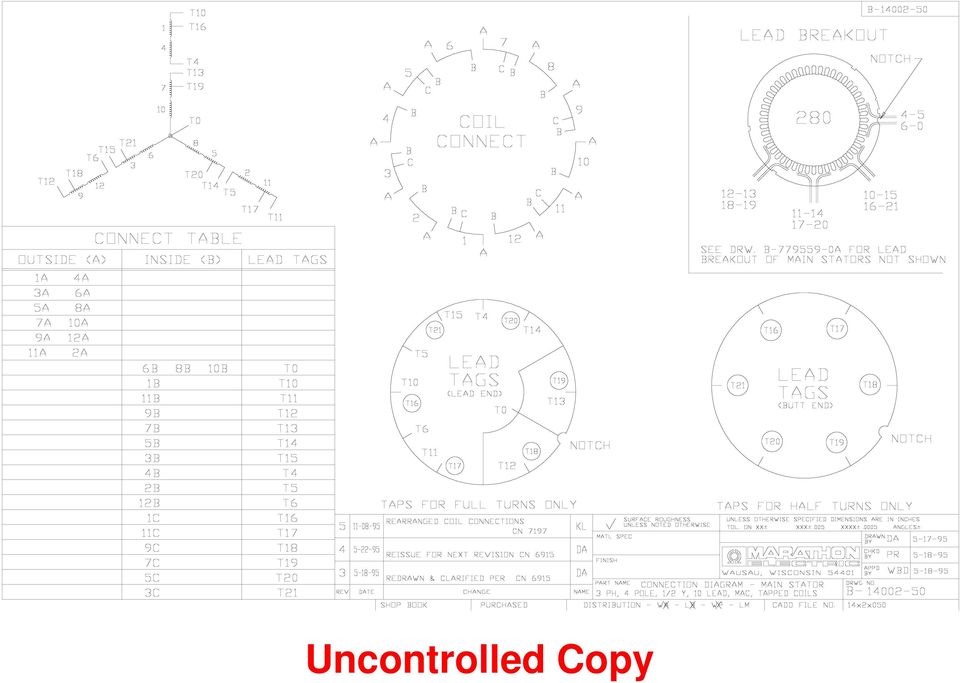
1 SERVICE SHOP NOTES LIMA 7 MAC SELF VOLTAGE REGULATED GENERATORS Troubleshooting Tips Engine bogs down or stalls even at no load. Problem: Main stator has one or more taps wound or connected incorrectly. (99% probability). This problem is only seen with generators having taps on their main stator coils. It is not seen with the newer No Tap MAC designs. Solution: Use ohmmeter to check the resistance between the leads. 12 Lead Generator Procedure, Reference Connection Diagram : Check resistance from T13-T4. It should be some small number. Then check from T4-T16. It should be a little bit smaller or about the same if not easily detectable. Then check T13-T16. This should be almost zero. If T16-T4 is almost zero, swap the lead numbers from T13 and T16. Repeat the procedure for the other six sets of coils and leads. If the reading from T4-T16 is nearly equal to T4-T13, the internal connection between coil one and four is wrong. It must be broken and corrected. Repeat the procedure for the other six sets of coils and leads. 10 Lead Generator Procedure, Reference Connection Diagram : Check resistance from T10-T4. It should be some small number. Then check from T4-T16. It should be a little bit smaller or about the same if not easily detectable then check T10-T16. This should be almost zero. If T16-T4 is almost zero, swap the lead numbers from T10 and T16. Repeat the procedure for the other six sets of coils and leads. If the reading from T4-T16 is nearly equal to T4-T10, the internal connection between coil one and four is wrong. It must be broken and corrected. Repeat the procedure for the other six sets of coils and leads. Comment: It is not necessary for the conduct of this procedure to have a meter that is accurate for very small resistances. The actual value of specific resistances is not needed here. What is required, is to measure is the relative difference in values. No voltage Problem: Flash the field. See restoring residual magnetism procedures on page 4. Assuming the field was flashed and there are no defective diodes, the most common problem after rewinding is the wrong phase sequence on one or both 1

2 stators. In rare cases, the diodes are all in working order but there can be a poor connection on the rectifier assembly. Check all connections for corrosion. Solution: Swap lead numbers from two phases on one stator only. The main and exciter stator must have the opposite phase sequence to generate voltage. See the phase sequence reversal procedure detailed on pages 5 and 6 below. Good voltage but one or more tapped coils gets hot under load. Problem: The most common problem is swapping the main lead with the tap lead next to it. They both come out of the same slot and are easily mixed up. The tapped turn(s) are designed to carry no load shunt current only. If the leads are swapped, the tap carries shunt current and load current. This causes the tap to overheat. Example: See Example under "Engine bogs down". Solution: If the resistance from T4-T13 is less than T4-T16, then swap T13 & T16. Check and repeat for all other groups. Problem: Solution: Good voltage but one or more tapped coils gets hot without any load. Poor connection to all strands used for tapped coil. See "Connection" directions. Good voltage no load but very low voltage under full load. Problem: Assuming there is no exciter damage or defect, the most likely cause is incorrect main stator coil insertion. Solution: See Coil Insertion directions. Rewinding Tips For Tapped MAC Generators Coil Winding The taps should be the specified number of turns (usually 1 or 2) away from the start or end of the coil group. 250 frames have taps at the end of the coils and all others have taps at the beginning of the coils. Only the first or last coil of the coil group should be tapped. Taps are typically made with a small twist in the wire while winding the coils. Coil Insertion Using either , or as a reference, the coil insertion can be seen using the "Coil Connect" circle. Tapped coils have a "C" to denote the tap. Standard coils have "A" & "B" ends only. The "A" side of the coils lie in the bottom of the slot toward the "outside" of the core. The "B" side of the coils lie on top of another coil in the slot toward 2

3 the "inside" of the core. One side of the tapped coil occupies the same slot as the "B" end and the other side is four slots away from the "A" end. The tap can be made anywhere between these two points. Diagram and -134, used for 250 MAC only, have the taps on the opposite side. Using -31 instead of -133 on a 250 MAC may result in low voltage under load. Viewing the "Coil Connect" circle as shown, the coils are inserted in a counter-clockwise (CCW) direction. The "A" side is inserted first in a CCW direction. Coil end "A" is in the last slot to be inserted. The "B" side is then inserted. After insertion, coil ends "A" & "B" must be at the outer edges of the coil group. If they are inserted to the inside of the coil group, the unit may have low voltage under load. See Diagram 1. Inserting the coils in a clockwise direction is acceptable if done consistently. It may result in a reversed phase sequence though. LIMA 7 MAC MAIN STATOR COIL INSERTION DIAGRAM CORRECT METHOD Slots End "A" End "B" INCORRECT METHOD Slots End "A" End "B" DIAGRAM 1 Connections Coils are to be connected as shown in the "Connect Table". All coil ends and leads on the same line are connected together. Refer to the "Coil Connect" circle for coil 3

4 numbers. The "Lead Tag" circle is a physical representation of the lead locations after connecting but before lacing. It is used to speed connect time but the table contains all necessary information. Electrically they will be as shown in the schematic diagram. The tap lead must be electrically connected to all strands in the turn. If two strands of magnet wire are used per turn, the lead must be connected to both of them. Restoring Residual Magnetism The current necessary to magnetize the alternator field during operation is obtained from the exciter. Initially, upon starting the unit, voltage is induced into the main stator (armature) by the flux across the air gap supplied by the permanent magnets embedded in the poles of the main rotor. Current then flows through interconnecting leads to the shunt portion of the exciter stator which induces current in the exciter rotor. This current is then rectified to DC excitation current by the rotating rectifier, and fed to the main field windings via the main rotor leads further strengthening the main field until rated voltage is reached. The residual magnetism contained in the field poles of the main rotor may be lost or severely weakened when the unit is disassembled for rewinding or other service operation. Should the generator fail to build up voltage after being reassembled, a momentary short circuit of any two generator output leads while the unit is running at rated speed should be sufficient to correct this condition. This action is termed "Flashing the Field". If the voltage does not build up with the above procedure, an alternate method may be used. Apply either an alternating or direct current voltage of from 24 to 30 volts to any two generator output leads. (Again - this procedure is conducted with the generator running at rated speed) Do not make a firm connection, but rather touch the leads together until the generator voltage begins to rise and then remove. It is suggested that a 30 ampere fuse be inserted in the supply voltage circuit to prevent any damage in case the build-up power supply voltage is not removed quickly enough. Start the generator and observe voltage build-up. Re-flash field if generator voltage does not build up. Verify that generator speed is at, or slightly above rated nameplate speed. Ball Testing of Stator Windings A ball test is simply another method of testing a stator winding to check for proper connections. The equipment consists of a large steel ball usually 1 to 2 inches in diameter. The diameter should be slightly larger than the distance between two adjacent stator slots. Sometimes, an inner or outer race of a ball bearing is used. The winding is usually connected in the high voltage wye connection, and a reduced voltage (about 2 voltage) is applied to the output leads. The ball or race is then placed on the inside of the stator core. If the completed winding has been done properly, the ball will spin 4

5 around the inside of the core at an even or uniform rate. If the winding is improperly connected, the movement of the ball will be erratic, or perhaps no movement will occur. Reversing the Phase Sequence of a Rewound Stator. There have been many instances where a repair facility will rewind either a main stator or an exciter stator on a Lima 7 MAC generator, and then not be able to generate a voltage at the terminals during test running. In almost every case of this nature, the problem is either in a loss of residual magnetism, or with the phase sequence of the rewound stator. The phase sequence of the exciter stator must be opposite to that of the main stator, or the unit will not build up voltage. To correct an improper phase sequence problem, you will have to reverse the phase sequence of the rewound stator. To reverse the phase sequence of a stator winding, all lead tags of one phase of the stator will be switched with the leads the next phase, and then these renumbered leads will be connected to matching numbered leads of the original (non-rewound) stator. If both stators have been re- wound, reverse tag only one stator. Suggestion: After a stator rewind, run a ball test on both stators once they are installed in the frame and inter-connected. The ball in the main stator must rotate in the opposite direction to that of the exciter stator. If rotation is the same for both stators, reverse tag using the procedures below, and re-connect before preceding with installing the rotor assembly in generator. A. Reverse tagging of the main stator of a 12 lead MAC generator. Break apart the connections of leads T13, T16, T19, T22; and T14, T17, T20, T23. Working only on the leads of the main stator: Physically re-tag lead T13 - T14, and T14 - T13; T16 - T17, and T17 - T16; T19 - T20, and T20 - T19: T22 - T23, and T23 - T22. Leads T4, T5, T10, and T11 are out put leads. Re-tag T4 - T5, and T5 - T4; T10 - T11, and T11 -T10. You have now reversed the phase sequence of the exciter stator. Re-interconnect these leads to the main stator leads, re-install the splice insulation, bundle the entire group of interconnecting leads as before. Now connect the generator output leads for the proper connection, and retest. B. Reverse tagging of the main stator of a 10 lead MAC generator. Break apart the connections of leads T10, T16, T13, T19; and T11, T17, T14, T20. Working only on the leads of the main stator: Physically re-tag lead T10 - T11, and T11 - T10: T16 -T17 and T17 - T16: T13 - T14 and T14 -T13: T19 - T20 and T20 -T19. Since load leads T4 and T5 are output leads, simply swap their tags to make T4 become T5, and T5 to become T4. You have now reversed the phase sequence of the main stator. Re-interconnect these leads to the exciter stator leads, re-install the splice insulation, bundle the entire group of interconnecting leads as before. Now connect the generator output leads for the proper connection, and retest. It may well be that you will have to flash the field to achieve voltage build-up after this procedure. 5

6 Uncontrolled Copy

7 Uncontrolled Copy
4 LEAD DEDICATED SINGLE PHASE LIMA MAC GENERATOR MODELS 250MSL1185 AND 250MSL1152
 4 LEAD DEDICATED SINGLE PHASE LIMA MAC GENERATOR MODELS 250MSL1185 AND 250MSL1152 SERVICE PROCEDURE ELECTRICAL COMPONENT TESTING HI POTENTIAL TETS None of the windings, either rotating or stationary should
4 DEDICATED SINGLE PHASE LIMA MAC GENERATOR LIGHT TOWER DUTY MODELS 250MSL1278 AND 250MSL1299 SERVICE PROCEDURE ELECTRICAL COMPONENT TESTING
 HI POTENTIAL TESTS 4 DEDICATED SINGLE PHASE LIMA MAC GENERATOR LIGHT TOWER DUTY MODELS 250MSL1278 AND 250MSL1299 SERVICE PROCEDURE ELECTRICAL COMPONENT TESTING None of the windings, either rotating or
Welcome to Linear Controls Quarterly Training
 Welcome to Linear Controls Quarterly Training Introduction to Power Generation Objectives Supply attendees with basic knowledge of power generators and voltage regulators and provide the fundamentals of
DIRECT CURRENT GENERATORS
 DIRECT CURRENT GENERATORS Revision 12:50 14 Nov 05 INTRODUCTION A generator is a machine that converts mechanical energy into electrical energy by using the principle of magnetic induction. This principle
1. The diagram below represents magnetic lines of force within a region of space.
 1. The diagram below represents magnetic lines of force within a region of space. 4. In which diagram below is the magnetic flux density at point P greatest? (1) (3) (2) (4) The magnetic field is strongest
Single-Phase AC Synchronous Generator
 ST Series Single-Phase AC Synchronous Generator Instructions for Operation and Maintenance English to English translation by R.G. Keen, May 2004. ST Series of Single-Phase AC Synchronous Generators Description
Understanding the Alternator
 http://www.autoshop101.com THIS AUTOMOTIVE SERIES ON ALTERNATORS HAS BEEN DEVELOPED BY KEVIN R. SULLIVAN PROFESSOR OF AUTOMOTIVE TECHNOLOGY AT SKYLINE COLLEGE SAN BRUNO, CALIFORNIA ALL RIGHTS RESERVED
Principles and Working of DC and AC machines
 BITS Pilani Dubai Campus Principles and Working of DC and AC machines Dr Jagadish Nayak Constructional features BITS Pilani Dubai Campus DC Generator A generator consists of a stationary portion called
Lab 8: DC generators: shunt, series, and compounded.
 Lab 8: DC generators: shunt, series, and compounded. Objective: to study the properties of DC generators under no-load and full-load conditions; to learn how to connect these generators; to obtain their
The Charging System. Section 5. Charging System. Charging System. The charging system has two essential functions:
 The Charging System Charging System The charging system has two essential functions: Generate electrical power to run the vehicle s electrical systems Generate current to recharge the vehicle s battery
Motor Fundamentals. DC Motor
 Motor Fundamentals Before we can examine the function of a drive, we must understand the basic operation of the motor. It is used to convert the electrical energy, supplied by the controller, to mechanical
DC GENERATOR THEORY. LIST the three conditions necessary to induce a voltage into a conductor.
 DC Generators DC generators are widely used to produce a DC voltage. The amount of voltage produced depends on a variety of factors. EO 1.5 LIST the three conditions necessary to induce a voltage into
WINDING RESISTANCE TESTING
 WINDING RESISTANCE TESTING WINDING RESISTANCE TEST SET, MODEL WRT-100 ADWEL INTERNATIONAL LTD. 60 Ironside Crescent, Unit 9 Scarborough, Ontario, Canada M1X 1G4 Telephone: (416) 321-1988 Fax: (416) 321-1991
3.0 CHARACTERISTICS. AR Auxiliary Relay High Speed, High Threshold 41-759.3C
 41-759.3C the magnetic core upon energizing of the switch. When the switch closes, the moving contacts bridge two stationary contacts, completing the trip circuit. Also during this operation two fingers
ST Style Generator. Owners/Operators Manual
 ST Style Generator Owners/Operators Manual LLC 216 Airport Rd NE Milledgeville, GA 31061 478-453-9358-Office 478-457-5524- Tom Cell 478-251-2914- Chris Cell Table of Contents Page 2. Table of Contents
Lab 14: 3-phase alternator.
 Lab 14: 3-phase alternator. Objective: to obtain the no-load saturation curve of the alternator; to determine the voltage regulation characteristic of the alternator with resistive, capacitive, and inductive
SECTION 4 ELECTRIC MOTORS UNIT 17: TYPES OF ELECTRIC MOTORS
 SECTION 4 ELECTRIC MOTORS UNIT 17: TYPES OF ELECTRIC MOTORS UNIT OBJECTIVES After studying this unit, the reader should be able to Describe the different types of open single-phase motors used to drive
Unit 33 Three-Phase Motors
 Unit 33 Three-Phase Motors Objectives: Discuss the operation of wound rotor motors. Discuss the operation of selsyn motors. Discuss the operation of synchronous motors. Determine the direction of rotation
Equipment: Power Supply, DAI, Universal motor (8254), Electrodynamometer (8960), timing belt.
, Electrodynamometer (8960), timing belt.") Lab 12: The universal motor. Objective: to examine the construction of the universal motor; to determine its no-load and full-load characteristics while operating on AC; to determine its no-load and full-load
Lab 12: The universal motor. Objective: to examine the construction of the universal motor; to determine its no-load and full-load characteristics while operating on AC; to determine its no-load and full-load
DC generator theory. Resources and methods for learning about these subjects (list a few here, in preparation for your research):
:") DC generator theory This worksheet and all related files are licensed under the Creative Commons Attribution License, version 1.0. To view a copy of this license, visit http://creativecommons.org/licenses/by/1.0/,
DC generator theory This worksheet and all related files are licensed under the Creative Commons Attribution License, version 1.0. To view a copy of this license, visit http://creativecommons.org/licenses/by/1.0/,
TERMINAL MARKINGS AND INTERNAL WIRING DIAGRAMS SINGLE PHASE AND POLYPHASE MOTORS MEETING NEMA STANDARDS
 INTRODUCTION The following represents the most up-to-date information on motor terminal marking for proper connection to power source for all alternating current motors manufactured in accordance with
2. A conductor of length 2m moves at 4m/s at 30 to a uniform magnetic field of 0.1T. Which one of the following gives the e.m.f. generated?
 Extra Questions - 2 1. A straight length of wire moves through a uniform magnetic field. The e.m.f. produced across the ends of the wire will be maximum if it moves: a) along the lines of magnetic flux
Chapter 22: Electric motors and electromagnetic induction
 Chapter 22: Electric motors and electromagnetic induction The motor effect movement from electricity When a current is passed through a wire placed in a magnetic field a force is produced which acts on
The purposes of this experiment are to test Faraday's Law qualitatively and to test Lenz's Law.
 260 17-1 I. THEORY EXPERIMENT 17 QUALITATIVE STUDY OF INDUCED EMF Along the extended central axis of a bar magnet, the magnetic field vector B r, on the side nearer the North pole, points away from this
ABB ! CAUTION. Type COQ Negative Sequence Generator Relay. (50/60 Hertz) 41-161J. Instruction Leaflet
 41-161J. Instruction Leaflet") ABB Instruction Leaflet 41-161J Effective: May 1997 Supersedes I.L. 41-161H Dated July 1984 ( ) Denotes Change Since Previous Issue Type COQ Negative Sequence Generator Relay (50/60 Hertz)! CAUTION Before
ABB Instruction Leaflet 41-161J Effective: May 1997 Supersedes I.L. 41-161H Dated July 1984 ( ) Denotes Change Since Previous Issue Type COQ Negative Sequence Generator Relay (50/60 Hertz)! CAUTION Before
Chen. Vibration Motor. Application note
 Vibration Motor Application note Yangyi Chen April 4 th, 2013 1 Table of Contents Pages Executive Summary ---------------------------------------------------------------------------------------- 1 1. Table
ESPD8-301R MODEL ESP-D FAN COIL UNIT TROUBLESHOOTING GUIDE
 ESPD8-301R MODEL ESP-D FAN COIL UNIT TROUBLESHOOTING GUIDE Protected by one or more of the following U.S. Patents (3,507,354; 3,575,234; 3,596,936; 3,605,797; 3,685,329; 4,045,977; 4,698,982; 926,673 and
SX460. Generator Automatic Voltage Regulator Operation Manual
 SX460 Generator Automatic Voltage Regulator Operation Manual Self Excited Automatic Voltage Regulator Compatible with Newage SX460* * Use for reference purpose only and not a genuine Newage product. 1.
12-Volt Negative Ground Installation Instructions
 12-Volt Negative Ground Installation Instructions For Part Number: 1141, 1164, 1165, 1181 CAUTION!!! Before installing, please read the following important information... 1. The Ignitor is designed for
Edmund Li. Where is defined as the mutual inductance between and and has the SI units of Henries (H).
.") INDUCTANCE MUTUAL INDUCTANCE If we consider two neighbouring closed loops and with bounding surfaces respectively then a current through will create a magnetic field which will link with as the flux passes
INDUCTANCE MUTUAL INDUCTANCE If we consider two neighbouring closed loops and with bounding surfaces respectively then a current through will create a magnetic field which will link with as the flux passes
Permanent Magnet Motor Kit, Magnetic Reed Type. (SKY-ReedMotorKit) Instructions
 Instructions") Permanent Magnet Motor Kit, Magnetic Reed Type (SKY-ReedMotorKit) Instructions This kit contains powerful permanent magnets. Exercise caution when handling them as they can pull on iron tools and snap
Permanent Magnet Motor Kit, Magnetic Reed Type (SKY-ReedMotorKit) Instructions This kit contains powerful permanent magnets. Exercise caution when handling them as they can pull on iron tools and snap
Building the HVPS High Voltage Power Supply
 Introduction Building the HVPS High Voltage Power Supply Voltages higher than the LVPS provides kilovolts are needed in later experiments to get strong electric fields and to generate microwaves. The high-voltage
Power Plant Electrical Distribution Systems
 PDH Course E184 Power Plant Electrical Distribution Systems Gary W Castleberry, PE 2008 PDH Center 2410 Dakota Lakes Drive Herndon, VA 20171-2995 Phone: 703-478-6833 Fax: 703-481-9535 www.pdhcenter.com
Equipment: Power Supply, DAI, Wound rotor induction motor (8231), Electrodynamometer (8960), timing belt.
, Electrodynamometer (8960), timing belt.") Lab 13: Wound rotor induction motor. Objective: to examine the construction of a 3-phase wound rotor induction motor; to understand exciting current, synchronous speed and slip in this motor; to determine
Lab 13: Wound rotor induction motor. Objective: to examine the construction of a 3-phase wound rotor induction motor; to understand exciting current, synchronous speed and slip in this motor; to determine
CHAPTER 4 DESIGN OF INTEGRAL SLOT AND FRACTIONAL SLOT BRUSHLESS DC MOTOR
 47 CHAPTER 4 DESIGN OF INTEGRAL SLOT AND FRACTIONAL SLOT BRUSHLESS DC MOTOR 4.1 INTRODUCTION This chapter deals with the design of 24 slots 8 poles, 48 slots 16 poles and 60 slots 16 poles brushless dc
Automatic Voltage Regulator User s Manual
 Resp. dept. R&D We reserve all rights in this document and in the information contained therein. Reproduction, use or disclosure to third parties without express authority is strictly forbidden. Copyright
COMPUTER AIDED ELECTRICAL DRAWING (CAED) 10EE65
 10EE65") COMPUTER AIDED ELECTRICAL DRAWING (CAED) EE Winding Diagrams: (i) DC Winding diagrams (ii) AC Winding Diagrams Terminologies used in winding diagrams: Conductor: An individual piece of wire placed in the
COMPUTER AIDED ELECTRICAL DRAWING (CAED) EE Winding Diagrams: (i) DC Winding diagrams (ii) AC Winding Diagrams Terminologies used in winding diagrams: Conductor: An individual piece of wire placed in the
DC MOTOR ANALYSIS & TROUBLESHOOTING
 DC MOTOR ANALYSIS & TROUBLESHOOTING By Don Shaw Condition assessment of DC motors requires a basic understanding of the design and operating characteristics of the various types available: the series motor,
CONTROL PANEL INSTALLATION INSTRUCTIONS. Single Phase Simplex Page 2-7. 3-Phase Simplex Page 8-13
 CONTROL PANEL INSTALLATION INSTRUCTIONS Single Phase Simplex Page 2-7 3-Phase Simplex Page 8-13 Single Phase Simplex SXL21=3, SXL24=3, SXH21=3, and SXH24=3 Manufactured by SJE-Rhombus Installation Instructions
Motors and Generators
 Motors and Generators Electro-mechanical devices: convert electrical energy to mechanical motion/work and vice versa Operate on the coupling between currentcarrying conductors and magnetic fields Governed
Chapter 21: A Small Self-Powered Generator
 A Practical Guide to Free-Energy Devices Author: Patrick J. Kelly Chapter 21: A Small Self-Powered Generator A free-energy developer working in South Africa where it is difficult to find electronic components,
SINGLE PHASE MOTORS. INSTALLATION AND MAINTENANCE MANUAL March 21, 2006
 SINGLE PHASE MOTORS INSTALLATION AND MAINTENANCE MANUAL March 21, 2006 Irvine, California (800) 474-0520 Indianapolis, Indiana (800) 866-7973 Hamilton, Ontario (800) 809-0330 e-mail: [email protected]
FAULT FINDING MANUAL. For Stamford AC Generators
 FAULT FINDING MANUAL For Stamford AC Generators 1 SAFETY PRECAUTIONS Test procedures recommended in this manual assume that the reader is fully conversant with electrical safety principles, and is familiar
UNIT 3 AUTOMOBILE ELECTRICAL SYSTEMS
 UNIT 3 AUTOMOBILE ELECTRICAL SYSTEMS Automobile Electrical Structure 3.1 Introduction Objectives 3.2 Ignition System 3.3 Requirement of an Ignition System 3.4 Types of Ignition 3.4.1 Battery or Coil Ignition
Tuning Up DC Motors and Generators for Commutation and Performance
 Tuning Up DC Motors and Generators for Commutation and Performance Rich Hall- National Electrical Carbon Western Mining Electrical Association June 8, 2007, Billings Montana Sometimes your machine may
FAULT FINDING MANUAL For Self Excited and Separately Excited Generators
 FAULT FINDING MANUAL For Self Excited and Separately Excited Generators SAFETY PRECAUTIONS Before testing the generating set, read the generating set Installation Manual, and this Fault Finding Manual,
Simple Analysis for Brushless DC Motors Case Study: Razor Scooter Wheel Motor
 Simple Analysis for Brushless DC Motors Case Study: Razor Scooter Wheel Motor At first glance, a brushless direct-current (BLDC) motor might seem more complicated than a permanent magnet brushed DC motor,
Basics of Electricity
 Basics of Electricity Generator Theory PJM State & Member Training Dept. PJM 2014 8/6/2013 Objectives The student will be able to: Describe the process of electromagnetic induction Identify the major components
TROUBLESHOOTING GUIDE
 TROUBLESHOOTING GUIDE LESTRONIC II BATTERY CHARGER FOR MOTIVE POWER BATTERIES PLEASE SAVE THESE IMPORTANT SAFETY AND OPERATING INSTRUCTIONS For correct operation of the equipment, it is important to read
Type MG-6 Multi-Contact Auxiliary Relay
 Type MG-6 Multi-Contact Auxiliary Relay Instruction Leaflet: 41-753.1 N Effective: August 2008 Supersedes 41-753.1 M, Dated December 1999 ( ) Denotes Change Since Previous Issue Device Number: 94X, Y,
PANCAKE CAPACITOR GENERATOR Installation, Operation and Maintenance Manual
 PANCAKE CAPACITOR GENERATOR Installation, Operation and Maintenance Manual A Regal Brand TABLE OF CONTENTS INTRODUCTION 2 General Data 2 Initial Inspection 2 SAFETY 2 INSTALLATION 3 Location / Environment
Windshield Wiper Motors
 Windshield Wiper Motors Originally posted by Dan Masters, [email protected] Also see http://www.advanceautowire.com/ WIPER OPERATION: There are three major components to a wiper motor: Motor Rotary to linear
Troubleshooting accelerometer installations
 Troubleshooting accelerometer installations Accelerometer based monitoring systems can be tested to verify proper installation and operation. Testing ensures data integrity and can identify most problems.
A.Y. McDonald Mfg. Co. Troubleshooting Submersible and Jet Pumps
 A.Y. McDonald Mfg. Co. Troubleshooting Submersible and Jet Pumps Troubleshooting Submersible Pumps Fuse overload or circuit breaker trips when motor is started 1. Incorrect line voltage. Check the line
Prof. Krishna Vasudevan, Prof. G. Sridhara Rao, Prof. P. Sasidhara Rao. x x. x x. Figure 10: Cross sectional view
 4 Armature Windings Main field Commutator & Brush Compole field haft v Compensating winding Armature winding Yoke Figure 10: Cross sectional view Fig. 10 gives the cross sectional view of a modern d.c.
TROUBLESHOOTING PRELIMINARY
 TROUBLESHOOTING PRELIMINARY To troubleshoot, one must first have a working knowledge of the individual parts and their relation to one another. Must have adequate hand tools Must have basic instrumentation:
Chapter 9. Bonding and Grounding
 Chapter 9 Bonding and Grounding Objectives Describe why the cable should be bonded Describe bonding and grounding procedures Define Bonding and Grounding Explain Safety Benefits and intent of bonding and
SECTION 611 ACCEPTANCE PROCEDURES FOR TRAFFIC CONTROL SIGNALS AND DEVICES
 SECTION 611 ACCEPTANCE PROCEDURES FOR TRAFFIC CONTROL SIGNALS AND DEVICES 611-1 Description. This Section sets forth Contract acceptance procedures for installations of traffic control signals and devices
Preview of Period 16: Motors and Generators
 Preview of Period 16: Motors and Generators 16.1 DC Electric Motors What causes the rotor of a motor to spin? 16.2 Simple DC Motors What causes a changing magnetic field in the simple coil motor? 16.3
GLOLAB Two Wire Stepper Motor Positioner
 Introduction A simple and inexpensive way to remotely rotate a display or object is with a positioner that uses a stepper motor to rotate it. The motor is driven by a circuit mounted near the motor and
Understanding Generator Ripple Waveforms
 Understanding Generator Ripple Waveforms 2 Understanding Generator Ripple Waveforms Chapter Page Preliminary Information and Setup 3 Generator Theory 6 Generator Ripple Theory 15 Factors that Influence
. Failure. Analysis... Report...
 . Failure. Analysis... Report..... for (Generation Company) (Station) Purchase Order Number XXXX (Dated XX/XX/XXXX) Report N-XXXX-FA, Revision 0 Schulz Electric Company Job Number N-XXXX Motor ID Number
Motor Protection Voltage Unbalance and Single-Phasing
 Motor Protection Voltage Unbalance and Single-Phasing Cooper Bussmann contributes the following information, which is an excerpt from their 190-page handbook SPD Selecting Protective Devices Based on the
EVANS ELECTRONIC TEMPERATURE CONTROL TROUBLESHOOTING GUIDE for systems equipped with electric coolant valve and external PC board.
 EVANS ELECTRONIC TEMPERATURE CONTROL TROUBLESHOOTING GUIDE for systems equipped with electric coolant valve and external PC board. This Troubleshooting Guide covers the electric coolant valve and control
Tri-Homo Style Operation and Maintenance Instructions
 Tri-Homo Style Operation and Maintenance Instructions One Research Drive Stratford, CT 06615 (203) 375-0063 www.sonicmixing.com 1 Installation and Start-up Do not perform following adjustments without
SYNCHRONOUS MACHINE TESTING WITH MOTOR CIRCUIT ANALYSIS INSTRUMENTATION
 SYNCHRONOUS MACHINE TESTING WITH MOTOR CIRCUIT ANALYSIS INSTRUMENTATION Introduction Howard W. Penrose, Ph.D., CMRP Vice President, Engineering and Reliability Services Dreisilker Electric Motors, Inc.
A.V.R. R250. Installation and maintenance R250 0V E+ E- VOLT STAB FREQ. & L.A.M. CONFIG. 50Hz. 47.5Hz. 57Hz LAM 1 13% 2 25% OFF LAM OFF 9
 110 0V E+ E- VOLT STAB KNEE 47.5Hz OFF 9 SPECIAL 8 KNEE 65Hz 7 OFF KNEE 6 57Hz OFF 7 8 50Hz o 9 0 5 6 1 2 3 4 OFF 1 13% 2 25% 3 OFF 4 13% 5 25% 60Hz FREQ. & L.A.M. CONFIG. This manual concerns the alternator
STUDY GUIDE: ELECTRICITY AND MAGNETISM
 319 S. Naperville Road Wheaton, IL 60187 www.questionsgalore.net Phone: (630) 580-5735 E-Mail: [email protected] Fax: (630) 580-5765 STUDY GUIDE: ELECTRICITY AND MAGNETISM An atom is made of three
AC generator theory. Resources and methods for learning about these subjects (list a few here, in preparation for your research):
:") AC generator theory This worksheet and all related files are licensed under the Creative Commons Attribution License, version 1.0. To view a copy of this license, visit http://creativecommons.org/licenses/by/1.0/,
AC generator theory This worksheet and all related files are licensed under the Creative Commons Attribution License, version 1.0. To view a copy of this license, visit http://creativecommons.org/licenses/by/1.0/,
Application for Small Generator Facility Interconnection Tier 2, Tier 3 or Tier 4 Interconnection
 Application for Small Generator Facility Interconnection Tier 2, Tier 3 or Tier 4 Interconnection (See ARSD chapter 20:10:36 for the requirements for a Tier 2, Tier 3, or Tier 4 Interconnection.) Applicant/Interconnection
Principles of Adjustable Frequency Drives
 What is an Adjustable Frequency Drive? An adjustable frequency drive is a system for controlling the speed of an AC motor by controlling the frequency of the power supplied to the motor. A basic adjustable
TABLE OF CONTENTS. I. TROUBLESHOOTING... 2 - Section 1.01: Common Problems/Solutions... 2
 BAL Accu-Slide System I. Table of Contents TABLE OF CONTENTS I. TROUBLESHOOTING... 2 - Section 1.01: Common Problems/Solutions... 2 II. GETTING STARTED... 5 - Section 2.01: Tools You Will Need... 5 - Section
The DC Motor/Generator Commutation Mystery. Commutation and Brushes. DC Machine Basics
 The DC Motor/Generator Commutation Mystery One small, yet vital piece of the DC electric motor puzzle is the carbon brush. Using the correct carbon brush is a key component for outstanding motor life,
Introduction. Upon completion of Basics of AC Motors you should be able to:
 Table of Contents Introduction...2 AC Motors...4 Force and Motion...6 AC Motor Construction... 12 Magnetism... 17 Electromagnetism... 19 Developing a Rotating Magnetic Field...24 Rotor Rotation...29 Motor
(3) Explosion proof. Designed to prevent ignition of any explosive gases or dust and dirt which may surround the motor.
 Explosion proof. Designed to prevent ignition of any explosive gases or dust and dirt which may surround the motor.") ELECTRIC MOTORS Enclosures for Motors Types of motor enclosures generally used in farm applications: (1) Open type; drip proof or splash-proof. A general purpose motor for use in dry locations which are
ELECTRIC MOTORS Enclosures for Motors Types of motor enclosures generally used in farm applications: (1) Open type; drip proof or splash-proof. A general purpose motor for use in dry locations which are
Physical Address: City: State: Zip Code:
 Application for Small Generator Facility Interconnection Tier 2, Tier 3 or Tier 4 Interconnection (For Small Generator Facilities with Electric Nameplate Capacities of 10 MW and less) Applicant Contact
PS-6.2 Explain the factors that determine potential and kinetic energy and the transformation of one to the other.
 PS-6.1 Explain how the law of conservation of energy applies to the transformation of various forms of energy (including mechanical energy, electrical energy, chemical energy, light energy, sound energy,
Rebuild Instructions for 70001 and 70010 Transmission
 Rebuild Instructions for 70001 and 70010 Transmission Brinn, Incorporated 1615 Tech Drive Bay City, MI 48706 Telephone 989.686.8920 Fax 989.686.6520 www.brinninc.com Notice Read all instructions before
AND8008/D. Solid State Control Solutions for Three Phase 1 HP Motor APPLICATION NOTE
 Solid State Control Solutions for Three Phase 1 HP Motor APPLICATION NOTE INTRODUCTION In all kinds of manufacturing, it is very common to have equipment that has three phase motors for doing different
Service and Maintenance. SEW-EURODRIVE Driving the world
 SEW Brakes Service and Maintenance 2 Objectives Upon completion of this session, you will be able to do the following: - Identify the components of an SEW brakemotor - Explain the operation of the SEW
Direct Current Motors
 Direct Current Motors DC MOTORS The DC machine can operate as a generator and as a motor. Chap 5. Electrical Machines by Wildi, 6 e Lecturer: R. Alba-Flores Alfred State College Spring 2008 When a DC machine
Wind Turbine. Designed by Dave Mussell
 Wind Turbine Designed by Dave Mussell Introduction... 1 Build It!... 2 Tools... 2 Materials... 2 Templates... 3 Construction Steps... 4 Part A. Frame and Base... 4 Part B. Making the Coils... 7 C. Build
Essential Electrical Concepts
 Essential Electrical Concepts Introduction Modern vehicles incorporate many electrical and electronic components and systems: Audio Lights Navigation Engine control Transmission control Braking and traction
VOLTAGE REGULATOR AND PARALLEL OPERATION
 VOLTAGE REGULATOR AND PARALLEL OPERATION Generator sets are operated in parallel to improve fuel economy and reliability of the power supply. Economy is improved with multiple paralleled generators by
Service Information CALIBRATION PROCEDURE AND TROUBLESHOOTING FOR LINEAR GOVERNOR CONTROLLERS NOTE
 Service Information Calibration & Adjustments CALIBRATION PROCEDURE AND TROUBLESHOOTING FOR LINEAR GOVERNOR CONTROLLERS Part Number DYN1-10752-000-0-12/24 DYN1-10752-001-0-12/24* DYN1-10753-000-0-12/24
Rotary Phase Converters
 FACTS from Ronk Electrical Industries, Inc. Bulletin 11981 Rotary Phase Converters ROTOVERTER Pat. No. 3,670,238 ROTO-CON Pat. No. 4,158,225 What are the ROTO-CON and ROTOVERTER power converters? The ROTO-CON
Compressor Service & Maintenance Manual
 Compressor Service & Maintenance Manual C Series COMPRESSOR (D)C1103 (D)C1203 (D)C2106 (D)C2206 (D)C3210 Copyright 2006 DCI. All Rights Reserved. 92311, Rev. C, 08/13 1 C1000 Series Service & Maintenance
Electrical Domestic Appliances (EDA)
") 14 Electrical Domestic Appliances (EDA) Paper-I Theory 40 Practical - 60 Unit. I : Current Electricity: Electricity as a source of energy, definition of resistance, voltage, current, power, energy and
14 Electrical Domestic Appliances (EDA) Paper-I Theory 40 Practical - 60 Unit. I : Current Electricity: Electricity as a source of energy, definition of resistance, voltage, current, power, energy and
Magneto Timing. The selected wire(s) from the magneto(s) distributor must be connected to this cylinder. And the crankshaft/magneto must be spinning.
 from the magneto(s) distributor must be connected to this cylinder. And the crankshaft/magneto must be spinning.") Magneto Timing The two areas of timing a magneto are internal, and external. A number of things must occur at the same time, or in a well orchestrated sequence for the engine to function. Magneto Timing
Magneto Timing The two areas of timing a magneto are internal, and external. A number of things must occur at the same time, or in a well orchestrated sequence for the engine to function. Magneto Timing
Permanent Magnetic Generator Construction Manual
 Permanent Magnetic Generator Construction Manual http://hojomotor.com Our Team Doing an On-site Assembly in Peru http://hojomotor.com Section 1) Introduction This manual describes how to build a 'permanent
Effective: September 10, 2006 Vermont Attachment 1 to Rule 5.500 Public Service Board Page 1 of 6
 Public Service Board Page 1 of 6 STANDARD APPLICATION FOR INTERCONNECTION OF GENERATION RESOURCES IN PARALLEL TO THE ELECTRIC SYSTEM OF: (Interconnecting Utility) Preamble and Instructions: An owner of
MILWAUKEE SCHOOL OF ENGINEERING LABORATORY SESSION 5 MAGNETIZATION CURVE OF A DC GENERATOR
 ILWUKEE SCHL F ENGINEEING LBTY SESSIN 5 GNETIZTIN CUE F DC GENET CUTIN: High voltages are present in this Laboratory Experiment! Do not make any connections with the power on! The power must be turned
Ampere's Law. Introduction. times the current enclosed in that loop: Ampere's Law states that the line integral of B and dl over a closed path is 0
 1 Ampere's Law Purpose: To investigate Ampere's Law by measuring how magnetic field varies over a closed path; to examine how magnetic field depends upon current. Apparatus: Solenoid and path integral
AC Generators and Motors
 AC Generators and Motors Course No: E03-008 Credit: 3 PDH A. Bhatia Continuing Education and Development, Inc. 9 Greyridge Farm Court Stony Point, NY 10980 P: (877) 322-5800 F: (877) 322-4774 [email protected]
JANUS INTERNATIONAL CORPORATION INSTALLATION INSTRUCTIONS Pantheon Mini Operator
 JANUS INTERNATIONAL CORPORATION INSTALLATION INSTRUCTIONS Pantheon Mini Operator The Janus Pantheon mini operator does not typically require the provision of any additional site requirements other than
Digital Energy ITI. Instrument Transformer Basic Technical Information and Application
 g Digital Energy ITI Instrument Transformer Basic Technical Information and Application Table of Contents DEFINITIONS AND FUNCTIONS CONSTRUCTION FEATURES MAGNETIC CIRCUITS RATING AND RATIO CURRENT TRANSFORMER
Installation Instructions
 0.1.2....6.7..9 1 0.1.2....6.7..9 1 Installation Instructions Quick-Mount Visual Instructions for Mechanical Installation Quick-Mount Visual Instructions 1. Rotate the damper to its fail-safe position.
Micrio WS1 Replacement Wind Speed Sensor and WC1 Replacement Wind Compass Sensor for Raymarine ST50 and ST60 Wind Instruments. Rev 4.
 Micrio WS1 Replacement Wind Speed Sensor and WC1 Replacement Wind Compass Sensor for Raymarine ST50 and ST60 Wind Instruments. Rev 4.1 The Micrio WS1 Wind Speed Sensor and WC1 Compass Sensor are direct
SYNCHRONOUS MACHINES
 SYNCHRONOUS MACHINES The geometry of a synchronous machine is quite similar to that of the induction machine. The stator core and windings of a three-phase synchronous machine are practically identical
Current Transformers. Bonneville Power Administration. Steve Laslo For the Hands On Relay School (3-12) Revision 1.1. February 21, 2012 1
 Revision 1.1. February 21, 2012 1") Current Transformers Bonneville Power Administration Steve Laslo For the Hands On Relay School (3-12) Revision 1.1 February 21, 2012 1 Basic Theory: CT as a Voltage Transformer February 21, 2012 2 CT as
Current Transformers Bonneville Power Administration Steve Laslo For the Hands On Relay School (3-12) Revision 1.1 February 21, 2012 1 Basic Theory: CT as a Voltage Transformer February 21, 2012 2 CT as