Welcome to Linear Controls Quarterly Training
|
|
|
- Christal Henry
- 10 years ago
- Views:
Transcription
1 Welcome to Linear Controls Quarterly Training

2 Introduction to Power Generation

3 Objectives Supply attendees with basic knowledge of power generators and voltage regulators and provide the fundamentals of generator and voltage regulator field diagnostics.

4 A Few Words About Safety PLEASE REMEMBER SAFETY FIRST. If you are not sure of the instructions or procedures, seek qualified help before continuing. Before any service work is done, disconnect all power sources and, where appropriate, lock out all controls to prevent an unexpected startup of the generator set. Proper grounding in compliance with local and national electrical codes must be provided. These safety precautions are necessary to prevent potential serious personal injury, or even death.

5 A Few Words About Safety

6 A Few Words About Safety Whenever the generator is running, always assume and proceed as if voltage is present. Residual voltage is present at the generator leads and at the regulator panel connections, even with the regulator fuse removed. Caution must be observed. Otherwise, serious personal injury or death can result. Whenever solvents, cleaners, or flammable liquids are present, adequate ventilation must be available to avoid fire, explosion, and health hazards. Always avoid breathing vapors and use suitable personal protective equipment to prevent personal injuries (such as eyes, face, and hand protection). Repairs should only be attempted by qualified, trained people. Each installation will create its own set of circumstances. No manual can cover every possible situation.

7 Generator Basics In 1831 a scientific discovery was made which is considered one of the most important findings in scientific history. Mr. Michael Faraday discovered that if a conductor is moved through a magnetic field, an electrical voltage is generated. The magnitude of the induced voltage is directly proportional to the rate of change and the strength of the magnetic field. This natural phenomenon is identified as generator action and the law by which it is governed, is called Faraday s Law of Electro Magnetic Induction. We make use of Faraday s law of generator action by building a rotating electrical mass whose purpose is to change mechanical energy into an electrical alternating current.

8 Generator Basics There are many different types of generators: DC, Induction, Synchronous, etc. Each type has its own unique application, but all utilize the same basic principles of generator action. In this discussion we are most concerned with synchronous machines, their properties, characteristics, and performance.

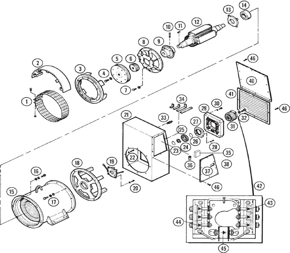
9 Components
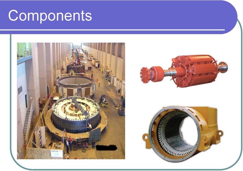
10 Components A synchronous machine consists of a stationary armature winding with many coils connected together to obtain a desired generator terminal voltage. The armature winding is placed into a slotted laminated steel core, with good magnetic properties. The number of slots is generally based upon a symmetrical polyphase winding where the coils of the windings are displaced by 120 electrical degrees.

11 Components A synchronous machine also consists of a rotor, which is a revolving field. Its function is to produce magnetic lines of force whose flux lines cut and induce an EMF (electromagnetic field) into the coils of the stator. The revolving field is essentially an even set of laminated pole cores with coils of wires embedded around the poles to create an exciting field. A DC current is fed into the revolving field by means of slip rings from a brush type rotary or static exciter, or more commonly today, a directly coupled rotating brushless exciter. The revolving field is designed for standard DC voltages of 63, 125, 250, and on very large machines 375 volts.


12

13
14

15 Electrical Flow with PMG
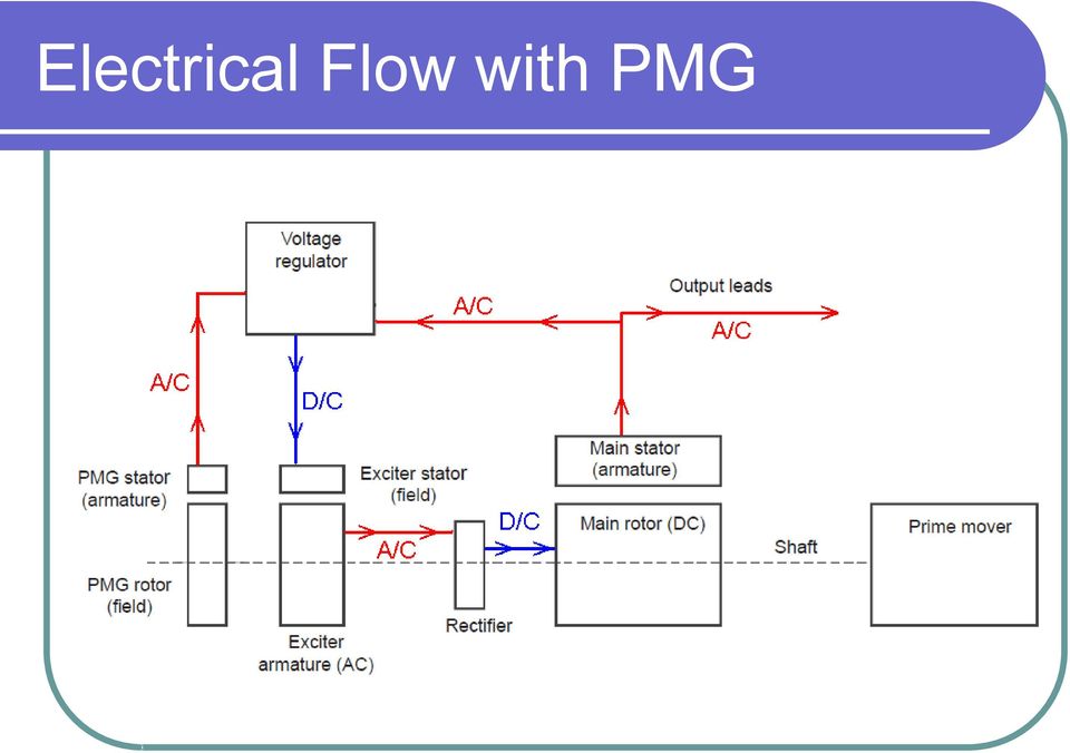
16 Electrical Flow with PMG The flow begins with PMG. 1. When rotating, the magnetic fields from the PMG rotor induces an A/C voltage into the PMG stator which flows to the voltage regulator. 2. The voltage regulator converts the A/C voltage to a D/C voltage which flows to the exciter stator. 3. The magnetic fields of the exciter stator induces an A/C voltage into the exciter armature with flows to the rectifier. 4. The rectifier converts the A/C to a D/C voltage that flows to the main rotor. 5. The magnetic fields of the main rotor induces an A/C voltage into the main stator that flows out through the output leads. 6. The voltage regulator samples the generator output A/C voltage and adjusts the D/C voltage output to the exciter stator to control the generator output voltage.

17 Electrical Flow without PMG
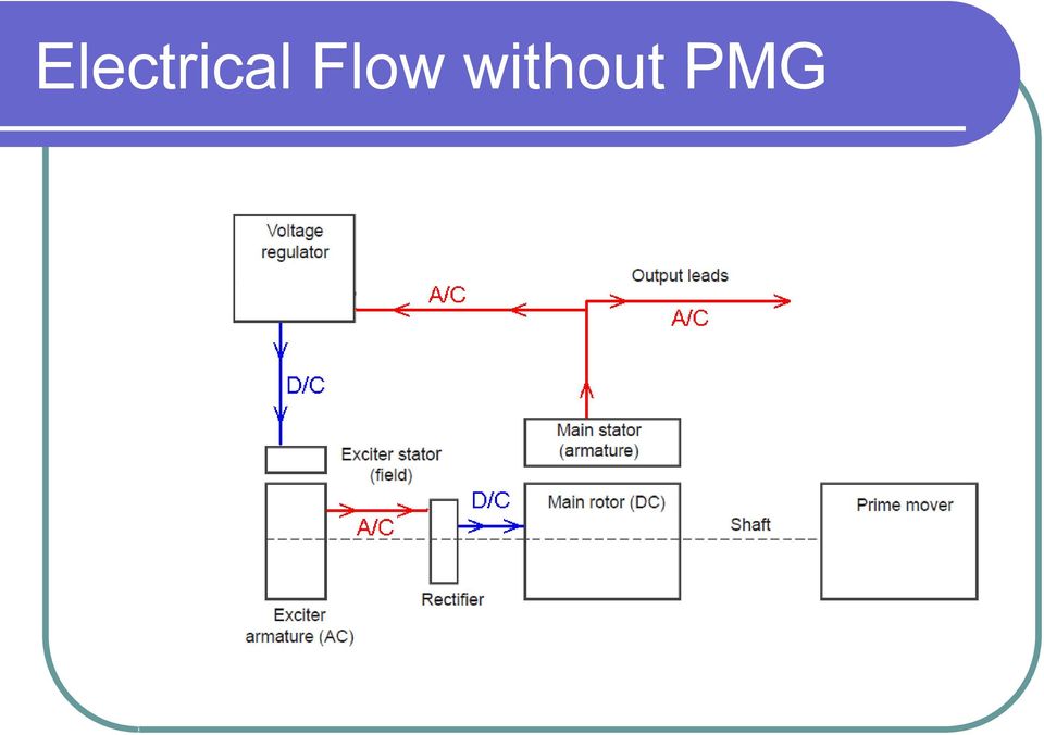
18 Electrical Flow without PMG Without a PMG the generator relies on the residual magnetism of the exciter stator to start the flow. 1. The residual magnetism of the exciter stator induces an A/C voltage into the exciter armature that flows to rectifier. 2. The rectifier converts the A/C voltage to a D/C voltage that flows to the main rotor. 3. The magnetic fields of the main rotor induces an A/C voltage into the main stator that flows out through the output leads. 4. The voltage regulator uses the generator output A/C voltage for its power supply and samples it to adjust the D/C voltage output to the exciter stator to control the generator output voltage.

19 PMG PMG stands for permanent magnet generator. The basic components of the PMG are the: 1. Rotor which contains the permanent magnets. 2. Stator which contains the field windings and the output leads.

20 PMG Depending on make and model of the generator you are servicing, the PMG may look very different from others.

21 Advantages of a permanent magnet generator: Provides an economical and simple means of reliable, responsive and stable input power to the voltage regulator. Enhances manual voltage control regulation as the PMG provides a more stable power source to the manual control. Provides full exciter power, regardless of alternator voltage, for motor starting and is a separate voltage source for use external to the generator set, such as a tachometer and relay options.
22 How the PMG Works The PMG exciter provides input power to the voltage regulator on a brushless revolving field generator to help maintain rated output voltage during sudden load changes. The PMG is a separate power source for the voltage regulator. In the event of a sudden load change due to a motor starting application or even a sudden short-circuit condition on the generator output, the PMG will supply rated voltage to the regulator. This will force the generator into saturation and supply the necessary output current to start the motor or clear the fault condition. The generator will produce up to 300% or more short-circuit current during a threephase fault condition. This is normally more than enough current to trip a properly sized circuit breaker.
23 How the PMG Works A revolving field brushless generator obtains excitation from a direct-connected brushless exciter. The voltage regulator regulates the generator output voltage by automatically regulating the DC current fed to the exciter field. The constant output voltage from the PMG pilot exciter is fed to the brushless exciter field. When the generator rotor begins to turn, the PMG rotating magnetic field produces voltage in the PMG stationary armature winding. The output voltage from this PMG armature winding is then used to power the voltage regulator.
24 How the PMG Works The rotating permanent magnet field assembly is mounted on the generator shaft. As shown in Figure 2, the PMG armature is mounted outboard for easy removal. Typically both the PMG and the exciter are mounted in the same frame. The PMG will provide constant power to the voltage regulator through a wide range of transient conditions. The only external input required is rotational energy from the prime mover.
25 Rectifiers There are many styles of rectifiers. They are typically made up of the same components, with the simple purpose of converting A/C voltage to D/C voltage.
26 Rectifiers Below is an exploded view of a rectifier
27 How the Rectifier works As the induced voltage flows from the exciter armature (rotor) to the main rotor it must pass through the rectifier diodes (Normally three standard and three reverse) causing the A/C voltage to be converted to pulsating D/C voltage.

28 How the Rectifier works This type of rectifier is referred to as a full-wave bridge rectifier. Full-wave rectification Bottom half of the wave is flipped and not clipped Yet still is pulsating DC Diode arrangement is called a bridge Diodes mounted on a heat sink
29 Diode Testing Some generators maybe equipped with an integrated rectifier instead of individual diodes and plates. The function and testing is electrically the same.
30 Diode Testing To check an ordinary silicon diode using a digital multimeter, put the multimeter selector switch in the diode check mode. Connect the positive lead of multimeter to the anode and negative lead to cathode of the diode. If multimeter displays a voltage between 0.5 to 0.8, we can assume that the diode is healthy. This is the test for checking the forward conduction mode of diode. The displayed value is actually the potential barrier of the silicon diode and its value ranges from 0.5 to 0.8 volts depending on the temperature. The voltage for a germanium diode test voltage is slightly lower, between volt.
31 Diode Testing Now connect the positive lead of multimeter to the cathode and negative lead to the anode. If the multimeter shows an infinite reading (over range), we can assume that the diode is healthy. This is the test for checking the reverse blocking mode of the diode.
32 Surge Suppressors The surge suppressor is a type of varistor, metal oxide. There many shapes and sizes of varistors depending on voltage and current demands.
33 How the Surge Suppressor Works A surge suppressor is a voltage dependent variable resistor. When disconnected or operating at a normal voltage level the surge suppressor has a very high resistance, near infinity.
34 How the Surge Suppressor Works When a surge or spike causes voltage rises above a predetermined point. The resistance of the suppressor begins to fall. This is know as clamping voltage. As long as the voltage on the line stays above clamping voltage the suppressor allows current to flow through it shunting the excess voltage.
35 Testing Surge Suppressors To test a varistor by the book requires equipment that you will not likely find on a production platform. However there are ways to determine whether or not the surge suppressor is the cause of problems in your generator.
36 Testing Surge Suppressors If you disconnect and check the resistance of a surge suppressor with a digital volt meter and the meter doesn t read out off limits. The suppressor is likely failed (internally shorted). If the generator has symptoms that are not spike or surge related and you suspect a failed suppressor. Remove the surge suppressor and retest the generator. If the problem is resolved with the suppressor removed, replace the suppressor with new replacement. If the problem still exists with the suppressor removed reinstall the suppressor continue with your diagnostics.
37 Main Rotor Field AC Impedance Test Theory: The main rotor resistance can be measured with a very accurate meter that is able to measure low (1 ohm) resistance, but it is difficult to determine if there are turn-to-turn shorts in the field pole windings. One shorted turn would only change a resistance reading on the order of one half of one percent. The AC impedance test measures the impedance (inductance and resistance) of the field pole coils. Shorted turns in the field pole windings change the coil inductance to a much greater degree than the resistance.
38 Main Rotor Field AC Impedance Test Step 1: The rotor must be supported on a nonmagnetic surface such as a wooden skid. Do not use a steel table that would create a magnetic short circuit between the poles. Step 2: Apply 120 volts AC to disconnected main rotor leads F1 and F2. Step 3: Measure and record voltages across each pole. Between points A and B, B and C, C and D, and D and E Step 4: The voltage readings should balance within one volt. Results: If the AC voltages are not balanced (30V ± 1V AC with 120V AC input) across each pole, the winding has shorted turns and should be rewound.
39 Megging Basics Insulation resistance is a measurement of the integrity of the insulating materials that separate the electrical windings from the generator s steel core. This resistance can degrade over time or due to contaminants (dust, dirt, oil, grease, and especially moisture). Most winding failures are due to a breakdown in the insulation system. In many cases, low insulation resistance is caused by moisture collected when the generator is shut down. The problem can be corrected simply by drying out the windings.
40 Megging Basics Normally the resistance of the insulation system is on the order of millions of ohms. It is measured with a device called a megger which is a megaohm meter (meg is for million) and a power supply. The power supply voltage varies, but the most common is 500 volts. A megger voltage over 500 is not recommended, except for measuring medium voltage (2400/4160) stators only.
41 Megging Basics The minimum acceptable value can be calulated using the following formula. Minimum Insulation Resistance = Gen. Voltage / Example: For a 480 volt generator 480 / = 1.48 Megohms If the reading is below the recommended value, the winding must be dried out or repaired.
42 Megger Types The two commonly use meggers used in the production field are the analog hand crank and the digital battery operated. This is an example of an analog hand crank type. The hand crank must be manually rotated to produce the output voltage for megging.
43 Megger Types This is an example of a digital megger. They typically resemble a digital multimeter and often have some the same basic functions. The output voltage for megging is produced by the internal batteries.
44 Megging Exciter Stator 1. Disconnect the F1 and F2 leads form the voltage regulator. Never subject the regulator to a megger. 2. Connect the F1 and F2 leads together to the positive megger lead. 3. Connect the negative megger lead to the generator frame. 4. Take the meg reading and record it. 5. If the reading is below the minimum spec the exciter stator must be dried or repaired.
45 Megging- Exciter Rotor 1. Disconnect the exciter rotor winding leads from the rectifier assembly. 2. Connect all the leads together to the positive megger lead. 3. Connect the negative megger lead to the generator frame. 4. Take the meg reading and record it. 5. If the reading is below the minimum spec the exciter stator must be dried or repaired.
46 Megging Main Stator Phase to Ground 1. Before megging, the ground T0 must be isolated. Make sure that L1,L2 and L3 are isolated from the bus and ground, also any external wiring must be disconnected from the stator leads. 2. Connect the positive megger lead to L1. 3. Connect the negative megger lead to the generator frame. 4. Take the meg reading and record it. 5. Repeat on L2 and L3. 6. If any of the meg reading are below the minimum spec the main stator must be dried or repaired.
47 Megging Main Stator Phase to Phase 1. Before megging, each phase ground must be separated and isolated. Make sure that L1,L2 and L3 are isolated from the bus and ground, also any external wiring must be disconnected from the stator leads. 2. Connect the positive megger lead to L1. 3. Connect the negative megger lead to L2. 4. Take the meg reading and record it. 5. Repeat for L1 to L3 and L2 to L3. 6. If any of the meg reading are below the minimum spec the main stator must be dried or repaired. Note: phase to phase megging is not possible on generators that the grounds are hard wired in generator windings. ie. 4 lead and 10 lead generators.
48 Megging PMG Stator 1. Disconnect both PMG leads form the voltage regulator. Never subject the regulator to a megger. 2. Connect both leads together to the positive megger lead. 3. Connect the negative megger lead to the generator frame. 4. Take the meg reading and record it. 5. If the reading is below the minimum spec the PMG stator must be dried or repaired.
49 Exciter Field Flashing Restoring residual magnetism/field flashing The direct current necessary to magnetize the revolving field is obtained from the exciter. Upon starting the generator, current and voltage is induced into the exciter by the magnetic lines of force set up by residual magnetism of the exciter field poles. Residual magnetism of the exciter Field poles may be lost or weakened by a momentary reversal of the field connection, a strong neutralizing magnetic field from any source, or nonoperational for a long time. If the generator fails to generate voltage after it has come up to rated speed, it may be necessary to restore residual magnetism.
50 Exciter Field Flashing 1. Open the output circuit breaker, and stop the engine. 2. Disconnect the exciter field coil wires F1 at the terminal F1 and F2 at the terminal F2, and connect the battery positive lead to the field coil lead F1. 3. Flash the field by momentarily touching the battery lead to the field coil circuit terminal F2. 4. Disconnect the battery leads. 5. Reconnect the field coil lead F1 to terminal F1, and reconnect the field coil lead F2 to terminal F2. 6. Start the generator, and check for voltage build up. Reflash if the generator output voltage does not build up, or flash with the generator running, the field coil wires connected to the regulator, and a 3-amp or larger diode off the positive terminal of the battery.
51 Exciter Field Flashing Do not flash the exciter with the generator running with out a diode between the battery positive and F1. Voltage back feed can cause the battery to explode. Do not firmly connect the negative battery lead to F2, only momentarily touch the negative lead to F2.
52 WYE Connections
53 WYE Connections
54 WYE Connections
55 WYE Connections
56 WYE Connections
57 WYE Connections
58 WYE Connections
59 Center Tap Connections The diagram shows the taps configured for high volt output. Typically 480 volts. The voltage reading phase to phase would read 480 vac. The voltage reading phase to ground would read 277 vac. By tapping onto T4&T7 or T8&T5 or T9&T6 you would read: Phase to phase 240 vac. Phase to ground 120 vac. By using center taps you can achieve 240 vac single phase, 120 vac single phase, and 120 vac three phase from a generator with a 480 vac three phase output.
60 Center Tap Connections The most common uses of centers taps are: 1. Voltage sensing for regulators, meters and end devices. 2. Voltage regulator supply power and panel control voltage supply. Warning: Since the center tap is connected before any current measuring devices only applications with very small current loads should be used with center tapping.
61 Voltage Regulators There are many voltage regulators available depending on the generator requirements. Most regulators offer the same basic functions and connections. For this discussion we will be referencing the Kato KCR 360 and Basler SR4.
62 Voltage Regulators The typical voltage regulator connections consist of : 1. Power supply 2. Sensing 3. Exciter output 4. Paralleling circuit ( if equipped)
63 Voltage Regulator Operation The voltage regulator uses an A/C voltage for it s power supply. The regulator converts this A/C voltage to a D/C voltage for the output to the generator exciter. The regulator automatically varies the D/C voltage output based on A/C voltage inputs to the sensing circuits from the generator and amperage inputs to the paralleling circuits( if equipped ). D/C voltage output can be manually varied by the internal voltage adjust rheostat and/or external voltage adjust rheostat ( if equipped ).
64 Voltage Regulator Bench Test The Voltage Regulator Bench Test can be used to test the basic function of a voltage regulator. Most voltage regulator operators manuals provide bench test instructions. Most operators manuals can be down loaded free of charge via the manufactures website. Bench testing can save time and money when dealing with a suspected failed regulator.
65 Voltage Regulator Bench Test (SR4A) 1. Move the wire on the sensing transformer (T1) to the terminal listed below: SR4A: Move to 120 V tap. SR8A: Move to 240 V tap. 2. Adjust the voltage stability potentiometer (R4) fully counter-clockwise (CCW). 3. Connect the voltage regulator as shown on the next page. The bulb should be 120 V and not more than 300 W. See Note 1 of the drawing for the SR8A. 4. Adjust the voltage adjust potentiometer for maximum resistance. 5. Connect the regulator to the power source. The bulb should flash on momentarily and then extinguish. 6. Slowly adjust the voltage adjust rheostat toward minimum resistance. The light bulb should reach full brilliance before minimum resistance is attained. (If the light does not illuminate, adjust the centering adjustment (R3). 7. At the regulating point, a small change in the voltage adjust potentiometer should turn the light bulb on or off. Note: If the light stays on, the regulator is defective. 8. This test may not reveal a stability problem, however, rotating the stability adjustment (R4) should affect the light's turn on/turn off time. 9. Before reinstalling the voltage regulator into the system, reconnect the sensing transformer (T1) as it was before performing Step 1.
66 Voltage Regulator Bench Test (SR4A)
67 Voltage Regulator Bench Test (KCR 360) Voltage regulator operational test: Use the following test procedure to determine if the regulator is basically operational: 1. Connect regulator as shown on the next page. 2. Connect internal wire from terminal E-3 to the 120 volt tap on sensing transformer T1. 3. Connect jumper across terminals CT1 and CT2. 4. Adjust the external voltage adjust for maximum resistance (complete counterclockwise position). 5. Connect light bulb across terminals F+ and F- and wires to terminal El, E3, P1 and P2 as shown in Figure Connect to 120 Vac power source. 7. Turn the external voltage adjust clockwise. Before reaching the maximum clockwise position the bulb should come on to near full brilliance. 8. At the regulating point a small change in adjustment of the external voltage adjust rheostat should turn the light on or off. If the light does not come on or stays on at full brilliance, the regulator is probably defective. 9. Before re-installing in generating system, connect regulator as it was before steps 2, 3, and 4.
68 Voltage Regulator Bench Test (KCR 360)
69 Generator Drying Electrical components must be dried before placing in operation if tests indicate that the insulation resistance is below a safe value. Machines that have been idle for sometime in unheated and damp locations may have absorbed moisture. Sudden changes in temperature can cause condensation or the generator may have become wet by accident. Windings should be dried out thoroughly before being put into service.
70 Generator Drying Space Heaters Electric space heaters can be installed inside of the generator. When energized (from a power source other than the generator), they will heat and dry the inside of the generator. If an alternate source of electricity is not available, enclose the generator with a covering and insert heating units to raise the temperature F (8 10 C) above the temperature outside of the enclosure. Leave a hole at the top of the enclosure to permit the escape of moisture.
71 Generator Drying Oven Place the machine in an oven and bake it at a temperature not to exceed 194 F (90 C). The voltage regulator and any electronic component accessories must be removed from the generator when using this method. Forced Air A portable forced air heater can be used by directing heat into the air intake (conduit box) and running the generator with no load and without excitation (this can be accomplished by removing the regulator fuse). Heat at point of entry should not exceed 150 F (66 C).
72 Generator Drying Short Circuit Method 1. The generator can be dried out quickly and thoroughly by using this method. 2. Disconnect exciter leads F1 and F2 from the regulator. 3. Connect a battery or other DC power source of approximately volts to the exciter leads F1 and F2. An adjustable voltage source is desirable, however a rheostat (rated approximately 2 amps) in series with the DC power source will work. 4. Short circuit the generator output lead wires to each other (L1 to L2 to L3). If using jumpers, be sure they are large enough to carry full load amperage. 5. Start the generator and measure the current through the output leads with a clip-on ammeter. 6. Adjust the voltage source to produce approximately 80% of the rated AC nameplate amps, but in no case exceed nameplate amps. If an adjustable source is not available and current is excessive, use a lower DC source voltage or a larger resistor in series with the source. 7. Running time will be determined by the amount of moisture present in the machine. Insulation resistance checks should be taken every one to four hours until a fairly constant value is obtained. 8. After the generator is dry and the insulation resistance is brought up to specifications, remove the short circuit from the line leads, disconnect the DC source, and reconnect the F1 and F2 leads at the regulator. Be sure all connections are tight and correct before attempting to run the generator.
73 Formulas
74
75
FAULT FINDING MANUAL. For Stamford AC Generators
 FAULT FINDING MANUAL For Stamford AC Generators 1 SAFETY PRECAUTIONS Test procedures recommended in this manual assume that the reader is fully conversant with electrical safety principles, and is familiar
FAULT FINDING MANUAL For Self Excited and Separately Excited Generators
 FAULT FINDING MANUAL For Self Excited and Separately Excited Generators SAFETY PRECAUTIONS Before testing the generating set, read the generating set Installation Manual, and this Fault Finding Manual,
DIRECT CURRENT GENERATORS
 DIRECT CURRENT GENERATORS Revision 12:50 14 Nov 05 INTRODUCTION A generator is a machine that converts mechanical energy into electrical energy by using the principle of magnetic induction. This principle
Single-Phase AC Synchronous Generator
 ST Series Single-Phase AC Synchronous Generator Instructions for Operation and Maintenance English to English translation by R.G. Keen, May 2004. ST Series of Single-Phase AC Synchronous Generators Description
The Charging System. Section 5. Charging System. Charging System. The charging system has two essential functions:
 The Charging System Charging System The charging system has two essential functions: Generate electrical power to run the vehicle s electrical systems Generate current to recharge the vehicle s battery
Understanding the Alternator
 http://www.autoshop101.com THIS AUTOMOTIVE SERIES ON ALTERNATORS HAS BEEN DEVELOPED BY KEVIN R. SULLIVAN PROFESSOR OF AUTOMOTIVE TECHNOLOGY AT SKYLINE COLLEGE SAN BRUNO, CALIFORNIA ALL RIGHTS RESERVED
4 LEAD DEDICATED SINGLE PHASE LIMA MAC GENERATOR MODELS 250MSL1185 AND 250MSL1152
 4 LEAD DEDICATED SINGLE PHASE LIMA MAC GENERATOR MODELS 250MSL1185 AND 250MSL1152 SERVICE PROCEDURE ELECTRICAL COMPONENT TESTING HI POTENTIAL TETS None of the windings, either rotating or stationary should
Power Plant Electrical Distribution Systems
 PDH Course E184 Power Plant Electrical Distribution Systems Gary W Castleberry, PE 2008 PDH Center 2410 Dakota Lakes Drive Herndon, VA 20171-2995 Phone: 703-478-6833 Fax: 703-481-9535 www.pdhcenter.com
SYNCHRONOUS MACHINE TESTING WITH MOTOR CIRCUIT ANALYSIS INSTRUMENTATION
 SYNCHRONOUS MACHINE TESTING WITH MOTOR CIRCUIT ANALYSIS INSTRUMENTATION Introduction Howard W. Penrose, Ph.D., CMRP Vice President, Engineering and Reliability Services Dreisilker Electric Motors, Inc.
Unit 33 Three-Phase Motors
 Unit 33 Three-Phase Motors Objectives: Discuss the operation of wound rotor motors. Discuss the operation of selsyn motors. Discuss the operation of synchronous motors. Determine the direction of rotation
R448 & R448 V50 A.V.R.
 Armature + 6- This manual is to be given to the end user F1 ST5 Field Slow fuse 250V 10 A with LAM without LAM 10 Yellow 11 Red 12 Black 9 Green X2 Z1 X1 Z2 E+ E- 0V 110 22 ST3 requency ST10 50Hz 60Hz
SECTION 4 ELECTRIC MOTORS UNIT 17: TYPES OF ELECTRIC MOTORS
 SECTION 4 ELECTRIC MOTORS UNIT 17: TYPES OF ELECTRIC MOTORS UNIT OBJECTIVES After studying this unit, the reader should be able to Describe the different types of open single-phase motors used to drive
ABB ! CAUTION. Type COQ Negative Sequence Generator Relay. (50/60 Hertz) 41-161J. Instruction Leaflet
 41-161J. Instruction Leaflet") ABB Instruction Leaflet 41-161J Effective: May 1997 Supersedes I.L. 41-161H Dated July 1984 ( ) Denotes Change Since Previous Issue Type COQ Negative Sequence Generator Relay (50/60 Hertz)! CAUTION Before
ABB Instruction Leaflet 41-161J Effective: May 1997 Supersedes I.L. 41-161H Dated July 1984 ( ) Denotes Change Since Previous Issue Type COQ Negative Sequence Generator Relay (50/60 Hertz)! CAUTION Before
Installation Instructions for Alarm Module Kit A043F059
 Instruction Sheet 07-2013 Installation Instructions for Alarm Module Kit A043F059 1 Introduction The information contained within is based on information available at the time of going to print. In line
26 3213.13 Diesel Engine Driven Generators Page 1 of 6
 Last Update: December 8, 2014 A. Description of System Consultant s Handbook Page 1 of 6 1. Provide a diesel engine driven electric generating unit, factory assembled, tested and certified to operate at
SALVAGING FLOOD DAMAGED ELECTRICAL EQUIPMENT
 SALVAGING FLOOD DAMAGED ELECTRICAL EQUIPMENT Overview In all drying out of electrical windings, the regulation of temperature should be controlled carefully. Maximum drying temperatures on windings should
ST Style Generator. Owners/Operators Manual
 ST Style Generator Owners/Operators Manual LLC 216 Airport Rd NE Milledgeville, GA 31061 478-453-9358-Office 478-457-5524- Tom Cell 478-251-2914- Chris Cell Table of Contents Page 2. Table of Contents
SYNCHRONOUS MACHINES
 SYNCHRONOUS MACHINES The geometry of a synchronous machine is quite similar to that of the induction machine. The stator core and windings of a three-phase synchronous machine are practically identical
A.V.R. R250. Installation and maintenance R250 0V E+ E- VOLT STAB FREQ. & L.A.M. CONFIG. 50Hz. 47.5Hz. 57Hz LAM 1 13% 2 25% OFF LAM OFF 9
 110 0V E+ E- VOLT STAB KNEE 47.5Hz OFF 9 SPECIAL 8 KNEE 65Hz 7 OFF KNEE 6 57Hz OFF 7 8 50Hz o 9 0 5 6 1 2 3 4 OFF 1 13% 2 25% 3 OFF 4 13% 5 25% 60Hz FREQ. & L.A.M. CONFIG. This manual concerns the alternator
Lab 14: 3-phase alternator.
 Lab 14: 3-phase alternator. Objective: to obtain the no-load saturation curve of the alternator; to determine the voltage regulation characteristic of the alternator with resistive, capacitive, and inductive
GENERATOR. 280 430 Frame Installation, Operation, and Maintenance Manual. Marathon Electric Mfg. Corp.
 GENERATOR 280 430 Frame Installation, Operation, and Maintenance Manual Marathon Electric Mfg. Corp. A REGAL-BELOIT COMPANY P.O. Box 8003 Wausau, WI 54402-8003 Phone: (715) 675 3359 Fax: (715) 675 8026
SHIP SERVICE GENERATORS (AC)
") CHAPTER 14 SHIP SERVICE GENERATORS (AC) INTRODUCTION All generators change mechanical energy into electrical energy. This is the easiest way to transfer power over distances. Fuel is used to operate the
CHAPTER 14 SHIP SERVICE GENERATORS (AC) INTRODUCTION All generators change mechanical energy into electrical energy. This is the easiest way to transfer power over distances. Fuel is used to operate the
4 DEDICATED SINGLE PHASE LIMA MAC GENERATOR LIGHT TOWER DUTY MODELS 250MSL1278 AND 250MSL1299 SERVICE PROCEDURE ELECTRICAL COMPONENT TESTING
 HI POTENTIAL TESTS 4 DEDICATED SINGLE PHASE LIMA MAC GENERATOR LIGHT TOWER DUTY MODELS 250MSL1278 AND 250MSL1299 SERVICE PROCEDURE ELECTRICAL COMPONENT TESTING None of the windings, either rotating or
SX460. Generator Automatic Voltage Regulator Operation Manual
 SX460 Generator Automatic Voltage Regulator Operation Manual Self Excited Automatic Voltage Regulator Compatible with Newage SX460* * Use for reference purpose only and not a genuine Newage product. 1.
R438 A.V.R. Installation and maintenance R 438. This manual is to be given to. the end user T10. Armature 6- Field X2 Z1 X1 Z2 E+ E- 0V 110 220
 Armature 6- This manual is to be given to the end user 1 T5 Field Slow fuse 250V 8 A with LAM without LAM 10 Yellow 11 Red 12 Black 9 Green X2 Z1 X1 Z2 E+ E- 0V 110 220 T3 quency T10 50Hz 60Hz LAM 13 %
ELECTRIC HEATER COMPANY Operating and Maintenance Manual For Immersion Heating Elements
 ELECTRIC HEATER COMPANY Operating and Maintenance Manual For Immersion Heating Elements HUBBELL ELECTRIC HEATER COMPANY P.O. BOX 288 STRATFORD, CT 06615 PHONE: (203) 378-2659 FAX: (203) 378-3593 INTERNET:
Automatic Voltage Regulator User s Manual
 Resp. dept. R&D We reserve all rights in this document and in the information contained therein. Reproduction, use or disclosure to third parties without express authority is strictly forbidden. Copyright
1. The diagram below represents magnetic lines of force within a region of space.
 1. The diagram below represents magnetic lines of force within a region of space. 4. In which diagram below is the magnetic flux density at point P greatest? (1) (3) (2) (4) The magnetic field is strongest
GLOLAB Two Wire Stepper Motor Positioner
 Introduction A simple and inexpensive way to remotely rotate a display or object is with a positioner that uses a stepper motor to rotate it. The motor is driven by a circuit mounted near the motor and
Lab 8: DC generators: shunt, series, and compounded.
 Lab 8: DC generators: shunt, series, and compounded. Objective: to study the properties of DC generators under no-load and full-load conditions; to learn how to connect these generators; to obtain their
Direct Current Motors
 Direct Current Motors DC MOTORS The DC machine can operate as a generator and as a motor. Chap 5. Electrical Machines by Wildi, 6 e Lecturer: R. Alba-Flores Alfred State College Spring 2008 When a DC machine
Generator Stator Protection, under/over voltage, under /over frequency and unbalanced loading. Ramandeep Kaur Aujla S.NO 250447392
 1 Generator Stator Protection, under/over voltage, under /over frequency and unbalanced loading By Ramandeep Kaur Aujla S.NO 250447392 ES 586b: Theory and applications of protective relays Department of
2. A conductor of length 2m moves at 4m/s at 30 to a uniform magnetic field of 0.1T. Which one of the following gives the e.m.f. generated?
 Extra Questions - 2 1. A straight length of wire moves through a uniform magnetic field. The e.m.f. produced across the ends of the wire will be maximum if it moves: a) along the lines of magnetic flux
Annex-A TECHNICAL SPECIFICATION
 Annex-A TECHNICAL SPECIFICATION FOR SUPPLY, INSTALLATION, TESTING AND COMMISSIONING OF 0.4kV (2,000kVA) DIESEL GENERATOR 1 1.0 SCOPE This specification covers the requirements of design, manufacture, delivery
CAT AVR V2.3. Instruction Manual. Voltage regulator for generators. March 2008
 CAT AVR V2.3 Voltage regulator for generators March 2008 Instruction Manual Warnings WARNING The system should not be installed, operated, serviced or modified except by qualified personnel who understand
AC-Synchronous Generator
 Design Description AC Generators come in two basic types synchronous and non-synchronous. Synchronous generators lock in with the fundamental line frequency and rotate at a synchronous speed related to
Oil and Coolant Circulating Heating System. Model - OCSM
 Oil and Coolant Circulating Heating System Model - OCSM Installation & Operation Manual 216280-000 REV 2 Identifying Your System The HOTSTART heating system is designed to heat fluids for use in marine
Preview of Period 16: Motors and Generators
 Preview of Period 16: Motors and Generators 16.1 DC Electric Motors What causes the rotor of a motor to spin? 16.2 Simple DC Motors What causes a changing magnetic field in the simple coil motor? 16.3
ECEN 1400, Introduction to Analog and Digital Electronics
 ECEN 1400, Introduction to Analog and Digital Electronics Lab 4: Power supply 1 INTRODUCTION This lab will span two lab periods. In this lab, you will create the power supply that transforms the AC wall
Equipment: Power Supply, DAI, Universal motor (8254), Electrodynamometer (8960), timing belt.
, Electrodynamometer (8960), timing belt.") Lab 12: The universal motor. Objective: to examine the construction of the universal motor; to determine its no-load and full-load characteristics while operating on AC; to determine its no-load and full-load
Lab 12: The universal motor. Objective: to examine the construction of the universal motor; to determine its no-load and full-load characteristics while operating on AC; to determine its no-load and full-load
Variable Transformers Product Design & Engineering Data
 Variable Transformers Product Design & Engineering Data Product Design & Engineering Data Type 1010B Cutaway General Information STACO ENERGY PRODUCTS CO. is a leading manufacturer of variable transformers,
Unified requirements for systems with voltages above 1 kv up to 15 kv
 (1991) (Rev.1 May 2001) (Rev.2 July 2003) (Rev.3 Feb 2015) Unified requirements for systems with voltages above 1 kv up to 15 kv 1. General 1.1 Field of application The following requirements apply to
Specifying a Variable Frequency Drive s
 Specifying a Variable Frequency Drive s Put on by Bruce Reeves and Jeremy Gonzales Dykman Electrical Covering the Western US For all of your VFD and Soft Start and Motor Needs How To Specify a Variable
UCI274C - Technical Data Sheet
 - Technical Data Sheet SPECIFICATIONS & OPTIONS STANDARDS Newage Stamford industrial generators meet the requirements of BS EN 60034 and the relevant section of other international standards such as BS000,
UCI274H - Technical Data Sheet
 - Technical Data Sheet SPECIFICATIONS & OPTIONS STANDARDS Newage Stamford industrial generators meet the requirements of BS EN 60034 and the relevant section of other international standards such as BS000,
TROUBLESHOOTING PRELIMINARY
 TROUBLESHOOTING PRELIMINARY To troubleshoot, one must first have a working knowledge of the individual parts and their relation to one another. Must have adequate hand tools Must have basic instrumentation:
NATIONAL CERTIFICATE (VOCATIONAL)
") NATIONAL CERTIFICATE (VOCATIONAL) SUBJECT GUIDELINES ELECTRICAL PRINCIPLES AND PRACTICE NQF Level 4 September 2007 ELECTRICAL PRINCIPLES AND PRACTICE LEVEL 4 CONTENTS INTRODUCTION 1 DURATION AND TUITION
NATIONAL CERTIFICATE (VOCATIONAL) SUBJECT GUIDELINES ELECTRICAL PRINCIPLES AND PRACTICE NQF Level 4 September 2007 ELECTRICAL PRINCIPLES AND PRACTICE LEVEL 4 CONTENTS INTRODUCTION 1 DURATION AND TUITION
Chen. Vibration Motor. Application note
 Vibration Motor Application note Yangyi Chen April 4 th, 2013 1 Table of Contents Pages Executive Summary ---------------------------------------------------------------------------------------- 1 1. Table
PANCAKE CAPACITOR GENERATOR Installation, Operation and Maintenance Manual
 PANCAKE CAPACITOR GENERATOR Installation, Operation and Maintenance Manual A Regal Brand TABLE OF CONTENTS INTRODUCTION 2 General Data 2 Initial Inspection 2 SAFETY 2 INSTALLATION 3 Location / Environment
DC generator theory. Resources and methods for learning about these subjects (list a few here, in preparation for your research):
:") DC generator theory This worksheet and all related files are licensed under the Creative Commons Attribution License, version 1.0. To view a copy of this license, visit http://creativecommons.org/licenses/by/1.0/,
DC generator theory This worksheet and all related files are licensed under the Creative Commons Attribution License, version 1.0. To view a copy of this license, visit http://creativecommons.org/licenses/by/1.0/,
Rotary Phase Converters
 FACTS from Ronk Electrical Industries, Inc. Bulletin 11981 Rotary Phase Converters ROTOVERTER Pat. No. 3,670,238 ROTO-CON Pat. No. 4,158,225 What are the ROTO-CON and ROTOVERTER power converters? The ROTO-CON
GROUND DETECTION CIRCUITS FOR STATIONARY APPLICATIONS (IN PLAIN DOWN TO EARTH LANGUAGE)
") GROUND DETECTION CIRCUITS FOR STATIONARY APPLICATIONS (IN PLAIN DOWN TO EARTH LANGUAGE) Matthew Theriault Designer Hindle Power Inc. Easton, PA SCOPE AND PURPOSE OF THE PAPER Why do we bother to monitor
GROUND DETECTION CIRCUITS FOR STATIONARY APPLICATIONS (IN PLAIN DOWN TO EARTH LANGUAGE) Matthew Theriault Designer Hindle Power Inc. Easton, PA SCOPE AND PURPOSE OF THE PAPER Why do we bother to monitor
*ADVANCED ELECTRIC GENERATOR & CONTROL FOR HIGH SPEED MICRO/MINI TURBINE BASED POWER SYSTEMS
 *ADVANCED ELECTRIC GENERATOR & CONTROL FOR HIGH SPEED MICRO/MINI TURBINE BASED POWER SYSTEMS Jay Vaidya, President Electrodynamics Associates, Inc. 409 Eastbridge Drive, Oviedo, FL 32765 and Earl Gregory,
What Is Regeneration?
 What Is Regeneration? Braking / Regeneration Manual Regeneration Overview Revision 1.0 When the rotor of an induction motor turns slower than the speed set by the applied frequency, the motor is transforming
Product Guide AC Voltage Control Devices. Guide Guide. Popular Variable Transformers and AC Power Supplies. www.stacoenergy.com
 Popular Variable Transformers and AC Power Supplies Product Guide AC Voltage Control Devices Guide Guide Your Tailored Power Solutions Provider TM Staco Energy Products Co. has been a leading manufacturer
CONTROL PANEL INSTALLATION INSTRUCTIONS. Single Phase Simplex Page 2-7. 3-Phase Simplex Page 8-13
 CONTROL PANEL INSTALLATION INSTRUCTIONS Single Phase Simplex Page 2-7 3-Phase Simplex Page 8-13 Single Phase Simplex SXL21=3, SXL24=3, SXH21=3, and SXH24=3 Manufactured by SJE-Rhombus Installation Instructions
PI734D - Technical Data Sheet
 PI734D - Technical Data Sheet PI734D SPECIFICATIONS & OPTIONS STANDARDS Newage Stamford industrial generators meet the requirements of BS EN 60034 and the relevant sections of other national and international
PI734B - Technical Data Sheet
 PI734B - Technical Data Sheet PI734B SPECIFICATIONS & OPTIONS STANDARDS Newage Stamford industrial generators meet the requirements of BS EN 60034 and the relevant sections of other national and international
Rutland 913 Windcharger Fault Finding Guide
 Rutland 913 Windcharger Fault Finding Guide Document No. SM-133 Issue A LOW VOLTAGE CHARGE CURRENT? TE 4 REGULATOR TE 5 REG RETURN REG TO MANUFACTURER CHARGE CURRENT INTERMITTENT CHARGE CURRENT SUFFICIENT
t... - GENERATORS - / SWITCHABLE VOLTAGE TRAILER MOUNTED GENERATOR W b 0 WER PLANTS-Over OPERATION and MAINTENANCE INSTRUCTIONS 45 Years of Leadership
 - GENERATORS SWITCHABLE VOLTAGE TRAILER MOUNTED GENERATOR OPERATION and MAINTENANCE INSTRUCTIONS Attention: Read all instructions in this manual before attempting to operate or service your WlNCO generator.
Three-phase AC circuits
 Three-phase AC circuits This worksheet and all related files are licensed under the Creative Commons Attribution License, version 1.0. To view a copy of this license, visit http://creativecommons.org/licenses/by/1.0/,
Motors and Generators
 Motors and Generators Electro-mechanical devices: convert electrical energy to mechanical motion/work and vice versa Operate on the coupling between currentcarrying conductors and magnetic fields Governed
WINDING RESISTANCE TESTING
 WINDING RESISTANCE TESTING WINDING RESISTANCE TEST SET, MODEL WRT-100 ADWEL INTERNATIONAL LTD. 60 Ironside Crescent, Unit 9 Scarborough, Ontario, Canada M1X 1G4 Telephone: (416) 321-1988 Fax: (416) 321-1991
Essential Electrical Concepts
 Essential Electrical Concepts Introduction Modern vehicles incorporate many electrical and electronic components and systems: Audio Lights Navigation Engine control Transmission control Braking and traction
DC GENERATOR THEORY. LIST the three conditions necessary to induce a voltage into a conductor.
 DC Generators DC generators are widely used to produce a DC voltage. The amount of voltage produced depends on a variety of factors. EO 1.5 LIST the three conditions necessary to induce a voltage into
ATTACHMENT F. Electric Utility Contact Information Utility Name. For Office Use Only
 ATTACHMENT F CATEGORY 2 GENERATOR INTERCONNECTION APPLICATION FOR ALL PROJECTS WITH AGGREGATE GENERATOR OUTPUT OF MORE THAN 20 KW BUT LESS THAN OR EQUAL TO 150 KW Also Serves as Application for Category
Renewable Energy Laboratory for Engineering Students
 dspace User Conference 2010 India Sept 24 th 10 Renewable Energy Laboratory for Engineering Students H.T Jadhav, S. D. Joshi Rajarambapu Institute Of Technology ABSTRACT Renewal Energy is now included
Single Phase Soft Starter
 Single Phase Soft Starter Installation & Operating Manual 6/02 Table of Contents Section 1 General Information................................................... 1 1 General Description................................................
3053 Electrical Safety Training Program Course Outline
 3053 Electrical Safety Training Program Course Outline The following outline summarizes the major points of information presented in the program. The outline can be used to review the program before conducting
Equipment: Power Supply, DAI, Synchronous motor (8241), Electrodynamometer (8960), Tachometer, Timing belt.
, Electrodynamometer (8960), Tachometer, Timing belt.") Lab 9: Synchronous motor. Objective: to examine the design of a 3-phase synchronous motor; to learn how to connect it; to obtain its starting characteristic; to determine the full-load characteristic of
Lab 9: Synchronous motor. Objective: to examine the design of a 3-phase synchronous motor; to learn how to connect it; to obtain its starting characteristic; to determine the full-load characteristic of
Electrical Domestic Appliances (EDA)
") 14 Electrical Domestic Appliances (EDA) Paper-I Theory 40 Practical - 60 Unit. I : Current Electricity: Electricity as a source of energy, definition of resistance, voltage, current, power, energy and
14 Electrical Domestic Appliances (EDA) Paper-I Theory 40 Practical - 60 Unit. I : Current Electricity: Electricity as a source of energy, definition of resistance, voltage, current, power, energy and
Line Reactors and AC Drives
 Line Reactors and AC Drives Rockwell Automation Mequon Wisconsin Quite often, line and load reactors are installed on AC drives without a solid understanding of why or what the positive and negative consequences
Replace That Bad Diode
 Replace That Bad Diode A common problem in any restoration is fixing and replacing inoperative or missing electrical components. If the exact part cannot be located then the restorer is forced to improvise.
Battery Tester. GxT Incorporated, Cheboygan MI, U.S.A. All Rights Reserved E040-01G. 40 & 42HD Operator s Manual
 Battery Tester GxT Incorporated, Cheboygan MI, U.S.A. All Rights Reserved E040-01G 40 & 42HD Operator s Manual SPECIFICATIONS Measurement Range...Ferret 40... Ferret 42HD Battery Volts... 4.0 to 19.99...
BSNL TTA Question Paper-Instruments and Measurement Specialization 2007
 BSNL TTA Question Paper-Instruments and Measurement Specialization 2007 (1) Instrument is a device for determining (a) the magnitude of a quantity (b) the physics of a variable (c) either of the above
Principles and Working of DC and AC machines
 BITS Pilani Dubai Campus Principles and Working of DC and AC machines Dr Jagadish Nayak Constructional features BITS Pilani Dubai Campus DC Generator A generator consists of a stationary portion called
SECTION 26 29 23 VARIABLE FREQUENCY DRIVES
 SECTION 26 29 23 VARIABLE FREQUENCY DRIVES PART 1 GENERAL 1.01 SCOPE A. Furnish and install individual freestanding variable frequency AC drives (VFD) as shown on the Drawings and specified herein. 1.02
Motor Fundamentals. DC Motor
 Motor Fundamentals Before we can examine the function of a drive, we must understand the basic operation of the motor. It is used to convert the electrical energy, supplied by the controller, to mechanical
Type SA-1 Generator Differential Relay
 ABB Automation Inc. Substation Automation and Protection Division Coral Springs, FL 33065 Instruction Leaflet 41-348.11C Effective: November 1999 Supersedes I.L. 41-348.11B, Dated August 1986 ( ) Denotes
Electrical Grounding. Appendix C
 Appendix C Electrical Grounding Low-Voltage Equipment Grounding The most frequently cited Office of Safety and Health Administration (OSHA) electrical violation is improper occupational grounding of equipment
CHAPTER 2B: DIODE AND APPLICATIONS. D.Wilcher
 CHAPTER 2B: DIODE AND APPLICATIONS D.Wilcher 1 CHAPTER 2B: OBJECTIVES Analyze the operation of 3 basic types of rectifiers Describe the operation of rectifier filters and IC regulators Analyze the operation
Basics of Electricity
 Basics of Electricity Generator Theory PJM State & Member Training Dept. PJM 2014 8/6/2013 Objectives The student will be able to: Describe the process of electromagnetic induction Identify the major components
A/C-HEATER SYSTEM - AUTOMATIC
 A/C-HEATER SYSTEM - AUTOMATIC 1995 Volvo 850 1995-96 Auto. A/C-Heater Systems Volvo 850 * PLEASE READ THIS FIRST * WARNING: To avoid injury from accidental air bag deployment, read and carefully follow
Principles of Adjustable Frequency Drives
 What is an Adjustable Frequency Drive? An adjustable frequency drive is a system for controlling the speed of an AC motor by controlling the frequency of the power supplied to the motor. A basic adjustable
INSTALLATION AND MAINTENANCE INSTRUCTIONS FOR THREE PHASE INDUCTION MOTORS
 INSTALLATION AND MAINTENANCE INSTRUCTIONS FOR THREE PHASE INDUCTION MOTORS Frames 143T - 449TZ 5100 North IH 35 Round Rock, Texas 78681 Phone: 800-451-8798 512-255-4141 Fax: 512-244-5512 RECEIVING 1. Check
UNIT 3 AUTOMOBILE ELECTRICAL SYSTEMS
 UNIT 3 AUTOMOBILE ELECTRICAL SYSTEMS Automobile Electrical Structure 3.1 Introduction Objectives 3.2 Ignition System 3.3 Requirement of an Ignition System 3.4 Types of Ignition 3.4.1 Battery or Coil Ignition
KBIC Solid State SCR DC Motor Speed Controls See table 2 page 4 for KBIC models covered by this manual
 KBIC Solid State SCR DC Motor Speed Controls See table 2 page 4 for KBIC models covered by this manual Patented Ultra Fast CL Circuit Prevents Demagnetization in PM Motors Installation and Operating Instructions
12-Volt Negative Ground Installation Instructions
 12-Volt Negative Ground Installation Instructions For Part Number: 1141, 1164, 1165, 1181 CAUTION!!! Before installing, please read the following important information... 1. The Ignitor is designed for
PowerFlex Dynamic Braking Resistor Calculator
 Application Technique PowerFlex Dynamic Braking Resistor Calculator Catalog Numbers 20A, 20B, 20F, 20G, 22A, 22B Important User Information Solid-state equipment has operational characteristics differing
RC NETWORKS SALES GUIDE
 SALES GUIDE INTRODUCTION TO Recent developments in electronic equipment have shown the following trends: Increasing demands for numerical control machines, robotics and technically advanced appliances
INSTALLATION & SERVICE MANUAL. Display Panel
 INSTALLATION & SERVICE MANUAL Display Panel The PowerLine EMS TM is a specialized power distribution and energy management system intended to be used in recreational vehicles. The Control Module is housed
6/14/02 Chapter 14: Use of Electrical Test Equipment 1/20
 USE OF ELECTRICAL TEST EQUIPMENT Test equipment is necessary for determining proper set-up, adjustment, operation, and maintenance of electrical systems and control panels. The following is a general procedure
MTE SERIES RLW. World REACTORS USER MANUAL PART NO. INSTR 030 REL. 090930. 2009 MTE Corporation
 MTE SERIES RLW World REACTORS USER MANUAL PART NO. INSTR 030 REL. 090930 2009 MTE Corporation IMPORTANT USER INFORMATION NOTICE MTE Series RLW reactors are components designed to improve the reliability
3.0 CHARACTERISTICS. AR Auxiliary Relay High Speed, High Threshold 41-759.3C
 41-759.3C the magnetic core upon energizing of the switch. When the switch closes, the moving contacts bridge two stationary contacts, completing the trip circuit. Also during this operation two fingers
Instruction Manual. This manual covers models: 8-125E 60-18E 20-50E 80-13E 33-33E 150-7E 40-25E 300-3.5E 50-20E 600-1.7E
 DCS-E SERIES POWER SUPPLIES Instruction Manual This manual covers models: 8-125E 60-18E 20-50E 80-13E 33-33E 150-7E 40-25E 300-3.5E 50-20E 600-1.7E SORENSEN Division of Elgar 9250 Brown Deer Road San Diego,
PI144K - Winding 311 APPROVED DOCUMENT. Technical Data Sheet. Generator Solutions AS
 PI144K - Winding 311 Technical Data Sheet PI144K SPECIFICATIONS & OPTIONS STANDARDS TERMINALS & TERMINAL BOX Stamford industrial generators meet the requirements of BS EN 60034 and the relevant section
PI044E - Winding 311 APPROVED DOCUMENT. Technical Data Sheet
 PI044E - Winding 311 Technical Data Sheet PI044E SPECIFICATIONS & OPTIONS STANDARDS Stamford industrial generators meet the requirements of BS EN 60034 and the relevant section of other international standards
Induction Motor Theory
 PDHonline Course E176 (3 PDH) Induction Motor Theory Instructor: Jerry R. Bednarczyk, P.E. 2012 PDH Online PDH Center 5272 Meadow Estates Drive Fairfax, VA 22030-6658 Phone & Fax: 703-988-0088 www.pdhonline.org
DHANALAKSHMI COLLEGE OF ENGINEERING DEPARTMENT OF ELECTRICAL AND ELECTRONICS ENGINEERING EE2302 - ELECTRICAL MACHINES II UNIT-I SYNCHRONOUS GENERATOR
 1 DHANALAKSHMI COLLEGE OF ENGINEERING DEPARTMENT OF ELECTRICAL AND ELECTRONICS ENGINEERING Constructional details Types of rotors EE2302 - ELECTRICAL MACHINES II UNIT-I SYNCHRONOUS GENERATOR PART A 1.
Federal Wage System Job Grading Standard for Electrical Equipment Repairing, 2854. Table of Contents
 Federal Wage System Job Grading Standard for Electrical Equipment Repairing, 2854 Table of Contents WORK COVERED... 2 WORK NOT COVERED... 2 TITLES... 3 GRADE LEVELS... 3 HELPER AND INTERMEDIATE JOBS...