PJM Generator Interconnection X2-060 & Y1-068 East Mill 115 kv 0 MW Capacity / 50 MW Energy Combined Feasibility & System Impact Study Report
|
|
|
- Henry Patrick
- 7 years ago
- Views:
Transcription
1 PJM Generator Interconnection X2-060 & Y1-068 East Mill 115 kv 0 MW Capacity / 50 MW Energy Combined Feasibility & System Impact Study Report July 2012 DMS #708833v1

2 Introduction This Feasibility Study has been prepared in accordance with the PJM Open Access Transmission Tariff, 36.2 and 111, as well as the Feasibility Study Agreement between Interconnection Customer (IC), and PJM Interconnection, LLC (PJM), Transmission Provider (TP). The Interconnected Transmission Owner (ITO) is Virginia Electric and Power Company. Preface The intent of this Feasibility Study is to determine a plan, with preliminary cost and construction time estimates, to connect the subject generation interconnection project to the PJM network at a location specified by IC. As a requirement for interconnection, IC may be responsible for the cost of constructing Network Upgrades, which are facility additions, or upgrades to existing facilities, that are needed to maintain the reliability of the PJM and the underlying system. All facilities required for interconnection of a generation interconnection project must be designed to meet ITO technical specifications. The Feasibility Study estimates do not include the feasibility, cost, or time required to obtain property rights and permits for construction of the required facilities. IC is responsible for its right of way, real estate, and construction permit issues. General The queue project X2-060 was the 30 MW (0 MW Capacity) injection into the ITO area. Y1-068 was studied as an additional 20 MW (0 MW Capacity) injection at East Mill 115 kv substation in to the ITO area. The combine 50 MW represent generation not being consumed Behind the Meter by existing load at the facility. Project Y1-068 was evaluated for compliance with reliability criteria for summer peak conditions in Potential network impacts were as follows: Network Impacts: Impactful Contingencies (The following contingencies resulted in overloads identified below) None. Generator Deliverability (Single or N-1 contingencies for the Capacity portion only of the interconnection) Page 2

3 None. Multiple Facility Contingency (Double Circuit Tower Line Contingencies only with full energy output. Stuck Breaker and Bus Fault contingencies will be applied during the Impact Study) None. Contribution to Previously Identified Overloads (Overloads initially caused by prior Queue positions with additional contribution to overloading by this project. This project may have % allocation of cost responsibility which will be calculated and reported for the Impact Study.) None. Short Circuit (Report Overdutied breakers here) Not required. Stability and Reactive Power Requirement (Results of the dynamic studies should be inserted here) Will be provided as a revision to this report. Delivery of Energy Portion of Interconnection Request PJM also studied the delivery of the energy portion of this interconnection request. Any problems identified below are likely to result in operational restrictions to the project under study. The developer can proceed with network upgrades to eliminate the operational restriction at their discretion by submitting a Merchant Transmission Interconnection request. Only the most severely overloaded conditions are listed. There is no guarantee of full delivery of energy for this project by fixing only the conditions listed in this section. With a Transmission Interconnection Request, a subsequent analysis will be performed, which will study all overload conditions associated with the overloaded element(s) identified. None. ITO Analysis ITO requested an interconnection of one (1) 80 MW biomass generator, PJM queue X IC generator unit is located at Meadwestvaco Covington Mill Site, Covington, Virginia. IC desires to export a total of 50 MW to be injected into the Interconnection Transmission Owners distribution system as specified in the additional energy request Y The remaining generation will be consumed Behind the Meter. Page 3
 Will be provided as a revision to this report.")
4 Attachment Facilities Modifications are required to existing Westvaco and East Mill Substations to accommodate proposed interconnection. Modifications inside the substations will include: Metering Enclosure: Generator meter will be installed in a 36 inch wide metering enclosure to be supplied by ITO at IC expense and installed by IC and mounted indoors, inside the new 80 MVA generator switchgear room. Metering enclosure will be designated: Dominion Virginia Power Metering Enclosure. The center of the metering enclosure shall be mounted eye-level, with sufficient overhead clearance to allow lid to swing up and lock open. All secondary conductors between the metering PTs and CTs and generator meter cabinet will be #10 American Wire Gauge (AWG) and installed in National Electric Code (NEC)-approved conduit, provided and installed by IC. Meter enclosure will be bonded and grounded in accordance with NEC. Note: The metering enclosure described above must be accessible to ITO personnel for purposes of periodic testing and maintenance of the metering equipment. Metering enclosure will be secured under ITO lock and key, with a small auxiliary hatch available for IC to view watt-hour meter register readings. Auxiliary Power: If a 120 Volt AC ground fault circuit interrupter outlet is not located within ten (10) feet of meter enclosure, a set of two (2) #10 AWG conductors must be installed for the purpose of providing 120 Volt AC auxiliary power in the metering cabinet, and must be installed within NEC-approved conduit between the IC breaker panel and the metering cabinet. All conduit and conductors for auxiliary power shall be provided and installed by IC. Metering Instrument Transformers: The 15 kv metering current transformers (CT s) and potential transformers (PT s) will be purchased by IC, at IC expense and approved by ITO. Metering CTs and PTs will be installed Page 4

5 by IC in a compartment separate from the IC switchgear. The compartment containing the metering CT s and PT s will be secured under ITO lock and key and designated: Dominion Virginia Power Metering TX s. Note: H1 bushings of CT s should be turned to face generator, H2 bushings should be turned to face line-side. Generator Watt-Hour Meter: IC will install a standard, copper, dedicated telephone line at the ITO generator metering enclosure. IC will maintain the phone line for the sole purpose of allowing ITO to communicate with ITO metering equipment, and will not install any other telephone equipment (e.g. fax machine) on the phone line provided for the ITO metering equipment. IC will make available to ITO the phone number assigned to the dedicated phone line. Additional Watt-Hour Meters: An additional six (6) watt-hour meters will be installed to meter the excess generation injected into the ITO system through the six (6) existing transformers located in Westvaco and East Mill substations. These six (6) watt-hour meters will include dial-up POTS modems for communication. A new metering panel will be built by the ITO, at IC expense, and installed in East Mill Substation to accommodate the additional three (3) watt-hour meters for transformers #4, #5 and #6. The cost for this work is estimated to be $71, and be completed in three months. Page 5

6 New Attachment Facilities: Transfer trip equipment modifications for new generation. The cost of this equipment and modifications will be $220,409. Existing Attachment Facilities: Existing facilities required to provide this interconnection include: 1. Metering 2. Generator out of sync protection 3. Telemetering Equipment The existing facilities were installed under Purchase of Electricity Agreements in September 1975, September 1980, December 1983 and January, 2001 and are covered in the IC current Agreement for Electric Service dated September 1, Listed below are costs that were not paid upfront and must be paid before executing an ISA. After payment is received the charges will be carried over to the new ISA as facility charges at 0.54%: September 1975 $ 3,000 September 1980 $47,000 January 2001 $11,210 Total $61,210 Listed below are charges that were paid upfront and will be carried over to the new ISA as facility charges at 0.54%: September 1980 $20,350 December 1983 $26,107 Total $46,457 The IC will also be responsible for providing and maintaining telephone lines to the ITO metering equipment at the Point of Interconnection and provide all communication lines necessary to transmit data from the metering to PJM. Page 6

7 The estimated time for engineering, material acquisition and construction of this interconnection is approximately three months. Detailed engineering, costs, material lead times and construction time requirements will be determined as part of the Combined System Impact & Facilities Study. Technical Requirements: IC site will be interfacing with the ITO source in the following manner: IC facility is fed by both Westvaco Substation transformers #1, #2, and #3 sourced from the 138 kilovolt (kv) Bus #6 and lines 109 (East Mill) and 155 (Fudge Hollow) and East Mill Substation Transformers #4, #5 and #6 sourced from the 138 kv Bus #1 and lines 109 (Westvaco) and 161 (Low Moor). The load data for the pertinent sectionalizing devices are as follows: o Line 109 has a typical "light" loading of 0.0 MVA o Line 155 has a typical "light" loading of 0.0 MVA o Line 161 has a typical "light" loading of 6.7 MVA IC parallel operation will not be limited to any particular time or ITO circuit-loading condition. IC will be contracted to export power into the ITO system. Based on the minimum circuit loads given for the utility sectionalizing devices, the following minimum "Local Load to Customer Generation Capacity" ratios will apply for this installation: Utility Transmission Line Minimum Ratio Line Line Line These minimum ratios applicable for this installation will require the customer to have direct pilot wire tripping (or transfer trip) and an islanding scheme installed to ITO breakers L182, L282 and L382 in Westvaco Substation and to all three customer main breakers 7AUT4, 11AUT5 and 13AUT6 Page 7
 Bus #6 and lines 109 (East Mill) and 155 (Fudge Hollow) and East Mill Substation Transformers #4, #5 and #6 sourced from the 138 kv Bus #1 and lines 109 (Westvaco) and 161 (Low Moor).")
8 sourced from East Mill Substation. The islanding and direct trip control features are meant to ensure that a "prolonged" (or "permanent") islanding condition (with the customer generation supplying utility load in the absence of the utility source) will not be set-up. In addition, the direct tripping and islanding scheme function would aid in protecting the customer generation equipment from an out-ofstep reclosure of the utility source. In its current design, the protection scheme at the Westvaco and East Mill substations is set up to initiate tripping of both the ITO breakers and IC breakers during a system disturbance through basic overcurrent or breaker failure scheme for disturbances at the local level. With the addition of the new generation in the East Mill, the existing islanding scheme will be expanded and reconfigured to ITO current design. These direct tripping functions and expanded islanding scheme should be sufficient to sectionalize the IC generation for the opening of the respective devices and prevent an islanding condition. In addition, the base protection package described below will also be required. The required relay functions (each sectionalizing all of the customer's generation) and the corresponding setting ranges, applying for each of the designated ITO feeds, are listed in the following tables: Function Set Point Duration To Disconnection (seconds) Preferred Maximum 27 Under voltage 90% of nominal operating voltage Less than Overvoltage 106% to 110% of nominal operating voltage Less than U Underfrequency 59.0 to 59.5 Hz Less than O Overfrequency 60.5 to 61.0 Hz Less than Phase Time-Delay Overcurrent Set for minimum, with adequate load allowance Maintain proper coordination 51N Ground Time-Delay Overcurrent Set for minimum, with adequate imbalance allowance Maintain proper coordination Page 8

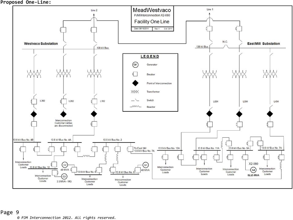
9 Proposed One-Line: Page 9
10 Appendix A Stability Study Results To be published separately as a revision to this combined study report. Page 10

Generation Interconnection System Impact Study Report. For. PJM Generation Interconnection Request Queue Position X1-114.
 Generation Interconnection System Impact Study Report For PJM Generation Interconnection Request Queue Position X1-114 Sandyston January 2012 Preface The intent of the System Impact Study is to determine
Generation Interconnection Feasibility Study Report-Web Version. PJM Generation Interconnection Request Queue Position Z1-055
 Generation Interconnection Feasibility Study Report-Web Version For PJM Generation Interconnection Request Queue Position Z1-055 South Bend Generation Project March 2014 PJM Interconnection 2014. All rights
PJM Merchant Transmission Request. Queue #R75. Mitchell Shepler Hill 138 Kv Feasibility / System Impact Study
 PJM Merchant Transmission Request Queue #R75 Mitchell Shepler Hill 138 Kv Feasibility / System Impact Study 413038v1a March 2007 PJM Interconnection 2007. All rights reserved. Preface The intent of the
Title 20 PUBLIC SERVICE COMMISSION. Subtitle 50 SERVICE SUPPLIED BY ELECTRIC COMPANIES. Chapter 02 Engineering
 Title 20 PUBLIC SERVICE COMMISSION Subtitle 50 SERVICE SUPPLIED BY ELECTRIC COMPANIES Chapter 02 Engineering Authority: Public Utility Companies Article, 2-121, 5-101 and 5-303, Annotated Code of Maryland.
Hyperlinks are Inactive
 Prepared by: NIB/EOB PLANNING GUIDE FOR SINGLE CUSTOMER SUBSTATIONS SERVED FROM TRANSMISSION LINES 05503 Department: Electric T&D Section: T&D Engineering and Technical Support Approved by: G.O. Duru (GOD)
Rule 5.500 Fast Track Analysis for National Life Insurance Co.
 Rule 5.500 Fast Track Analysis for National Life Insurance Co. For a 500 kw Solar array to be located at 155 Northfield Street in Montpelier, Vermont Green Mountain Power Pam Allen Date: 5/31/13 SECTION
TERMS AND CONDITIONS
 Virginia Electric and Power Company TERMS AND CONDITIONS XXIV. GENERATOR INTERCONNECTION STANDARD Electric generator interconnection service includes only the ability to interconnect an electric generator
FRCC Standards Handbook. FRCC Automatic Underfrequency Load Shedding Program. Revision Date: July 2003
 F R C C FRCC Standards Handbook FRCC Automatic Underfrequency Load Shedding Program Revision Date: July 2003 FRCC Underfrequency Load Shedding Program Modification and Approval Process Requests to modify
SPECIFICATION COG-2007
 Cleco Power LLC SPECIFICATION COG-2007 FOR PARALLEL OPPERATION OF CUSTOMER-OWNED GENERATION ON CLECO S ELECTRICAL SYSTEM Revised: March 7, 2014 CONTENTS ITEM NO. TITLE PAGE NO. 1.0 Scope 3 2.0 Policy On
Power Plant Electrical Distribution Systems
 PDH Course E184 Power Plant Electrical Distribution Systems Gary W Castleberry, PE 2008 PDH Center 2410 Dakota Lakes Drive Herndon, VA 20171-2995 Phone: 703-478-6833 Fax: 703-481-9535 www.pdhcenter.com
SDG&E Electric Distribution System Interconnection Handbook. <Revised as of 10/21/2015>
 TABLE OF CONTENTS 1 Introduction... 1 1.1 Purposes... 1 1.2 Applicability and Related Tariffs... 1 1.3 Interconnection Agreement Required... 1 1.4 Technical Requirement... 1
CUSTOMER REQUIREMENTS AT POWER SUBSTATIONS
 CUSTOMER REQUIREMENTS AT POWER SUBSTATIONS Customer Handout Date Aug 2, 2010 Version 1.0 File Name Customer Requirements At Power Substations Document Id Outside Plant Engineering 1 Table Of Contents 1.0
Approved Meter Sockets and Cabinets
 Single Unit Residential Guide 1 PHASE, 120/240 VOLT S METERING (Metering sockets and cabinets are supplied by Customer). Outdoor meter mounting height is 1730 mm ( 5 8 ) to center of meter ± 100 mm ( 4
16 West Coast Regional Plan
 16 West Coast Regional Plan 16.1 Regional overview 16.2 West Coast transmission system 16.3 West Coast demand 16.4 West Coast generation 16.5 West Coast significant maintenance work 16.6 Future West Coast
2a. IEM Indoor Metal Clad Medium Voltage Switchgear 15KV 16346-1. 2a. Section 16346 INDOOR METAL CLAD MEDIUM VOLTAGE SWTICHGEAR (Std.
 2a. IEM Indoor Metal Clad Medium Voltage Switchgear 15KV 16346-1 2a. Section 16346 INDOOR METAL CLAD MEDIUM VOLTAGE SWTICHGEAR (Std. Relays) Part 1 General 1.1 CONDITIONS AND REQUIREMENTS: A. Refer to
Fundamentals of Modern Electrical Substations Part 1: Mission of Electrical Substations and their Main Components
 Fundamentals of Modern Electrical Substations Part 1: Mission of Electrical Substations and their Main Components Course No: E02-010 Credit: 2 PDH Boris Shvartsberg, Ph.D., P.E., P.M.P. Continuing Education
Distribution Operations with High-penetration of Beyond the Meter Intermittent Renewables. Bob Yinger Southern California Edison April 15, 2014
 1 Distribution Operations with High-penetration of Beyond the Meter Intermittent Renewables Bob Yinger Southern California Edison April 15, 2014 Southern California Edison SCE provides power to: Nearly
Technical Requirements. For Generating Facilities Interconnecting. To The Distribution System. Salt River Project
 Technical Requirements For Generating Facilities Interconnecting To The Distribution System Salt River Project Effective June 6, 2012 1-1 TABLE OF CONTENTS 1. NOTICE OF DISCLAIMER AND USE OF REFERENCES
Customer Substation Manual 08/05/02
 Customer Substation Manual Table of Contents Section Page 2 of 85 Description 0 Preface 010.00 General 010.10 Information Required for the Review of New Customer Substations 010.20 New Customer Substation
SOLAR PV STANDARD ELECTRICAL PLAN Microinverter Systems for Single Family Dwellings
 *** Provide this document to the inspector along with ALL system installation instructions *** Project Address: Scope: Standard plan for the installation of grounded microinverter solar PV systems, not
AMFA-27 AMFA-29. Operator s Manual & Installation Instructions. Rev. 2.5
 AMFA-27 AMFA-29 Operator s Manual & Installation Instructions Rev. 2.5 Date: 17 July, 2010 Permanently-connected, utility Interactive, single-phase, inverters Model AMFA-27 WIND TURBINE INVERTER (240 VAC
INTRODUCTION TO SYSTEM PROTECTION. Hands-On Relay School 2012
 INTRODUCTION TO SYSTEM PROTECTION Hands-On Relay School 2012 CONGRATULATIONS On choosing the field of system protection. It is an exciting, challenging profession. System protection has changed considerably
Submit shop drawings for equipment provided under this section Shop drawings shall indicate:
 Section 16435 - SWITCHBOARDS Introduction Part 1 - General Reference The work under this section is subject to requirements of the Contract Documents including the General Conditions, Supplementary Conditions,
Generation Interconnection Facilities Study Report. For. PJM Generation Interconnection Request Queue Position R11. South River
 Generation Interconnection Facilities Study Report For PJM Generation Interconnection Request Queue Position R11 South River May 2012 Transmission Owner Facilities Study Summary Description of Project
PG&E Transmission Interconnection Handbook. Section L3: SUBSTATION DESIGN FOR LOAD-ONLY ENTITIES AND TRANSMISSION-ONLY ENTITIES
 Section L3: SUBSTATION DESIGN FOR LOAD-ONLY ENTITIES AND TRANSMISSION-ONLY ENTITIES PURPOSE This section provides substation design information for Load Entities interconnected at transmission voltage
F.C. Chan General Manager, CLP Engineering Ltd., Hong Kong SAR, China
 ELECTRIC POWER DISTRIBUTION SYSTEMS F.C. Chan General Manager, CLP Engineering Ltd., Hong Kong SAR, China Keywords: Distribution system planning, Load characteristics, Subtransmission Lines, Distribution
Digital Energy ITI. Instrument Transformer Basic Technical Information and Application
 g Digital Energy ITI Instrument Transformer Basic Technical Information and Application Table of Contents DEFINITIONS AND FUNCTIONS CONSTRUCTION FEATURES MAGNETIC CIRCUITS RATING AND RATIO CURRENT TRANSFORMER
ELECTRICAL INSULATION TESTING OF HV EQUIPMENT UP TO 33kV
 1. SCOPE This document details PowerSystems requirements for electrical testing of HV Equipment up to and including 33kV. 2. ISSUE RECORD This is a Reference document. The current version of Controlled
Inverter / Charger Installation General Operations and AC and DC Connections
 Inverter / Charger Installation General Operations and AC and DC Connections The Inverter is just one piece. Sometimes, a tendency is to mount the inverter and batteries, and make it work It is better
UNIVERSITY OF WASHINGTON Facilities Services Design Guide. Electrical. Metering and Monitoring. Basis of Design
 Basis of Design This section applies to the design, installation and integration of metering and monitoring equipment, including: hardware installed in the electrical service and distribution equipment,
INDUSTRIAL AND COMMERCIAL SERVICE TRANSFORMER & METERING INSTALLATION SPECIFICATION
 INDUSTRIAL AND COMMERCIAL SERVICE TRANSFORMER & METERING INSTALLATION SPECIFICATION February 2013 NOTE: If conflict exists between St. Thomas Energy s Conditions of Service and this document, the Conditions
OVERCURRENT & EARTH FAULT RELAYS. To study the protection of equipment and system by relays in conjunction with switchgear.
 OVERCURRENT & EARTH FAULT RELAYS Objective: To study the protection of equipment and system by relays in conjunction with switchgear. Theory: The function of a relay is to detect abnormal conditions in
IRRIGATION PUMPING Table of Contents - Section 900
 IRRIGATION PUMPING Table of Contents - Section 900 PARAGRAPH 900.1 GENERAL 1 900.2 METERING REQUIREMENTS 1 900.3 CUSTOMER S CONTROL EQUIPMENT 2 900.4 SERVICE CONDUCTOR REQUIREMENTS 2 900.5 RECOMMENDATIONS
SECTION 26 09 13 - POWER MONITOR FOR ELECTRICAL, STEAM CONDENSATE, AND WATER PART I - GENERAL
 SECTION 26 09 13 - POWER MONITOR FOR ELECTRICAL, STEAM CONDENSATE, AND WATER PART I - GENERAL 1.1 SUMMARY A. This section describes the requirements for the installation of Power Monitors and associated
N.J.A.C. 14:8-4 NET METERING FOR CLASS I RENEWABLE ENERGY SYSTEMS
 N.J.A.C. 14:8-4 NET METERING FOR CLASS I RENEWABLE ENERGY SYSTEMS 14:8-4.1 Scope This subchapter sets forth net metering requirements that apply to electric power suppliers, basic generation service providers
Generation and Transmission Interconnection Process
 PJM Manual 14A Generation and Transmission Interconnection Process Revision: 18 Effective Date: January 28, 2016 Prepared by Planning Division Generation Interconnection Department PJM 2016 Table of Contents
Nuclear Power Plant Electrical Power Supply System Requirements
 1 Nuclear Power Plant Electrical Power Supply System Requirements Željko Jurković, Krško NPP, zeljko.jurkovic@nek.si Abstract Various regulations and standards require from electrical power system of the
READ THIS MANUAL BEFORE PROCEEDING WITH THE INSTALLATION. FAILURE TO FOLLOW THE INSTALLATION INSTRUCTIONS MAY VOID YOUR WARRANTY!
 READ THIS MANUAL BEFORE PROCEEDING WITH THE INSTALLATION. FAILURE TO FOLLOW THE INSTALLATION INSTRUCTIONS MAY VOID YOUR WARRANTY! The main power to any existing system must be disconnected prior to the
Interconnection of Generators to EDI s Distribution System
 Interconnection of Generators to EDI s Distribution System May 22, 2002 This document sets forth the guidelines for connecting a power producing facility to the Alberta Interconnected Electric System through
National Craft Assessment and Certification Program S P E C I F I C A T I O N S
 National Craft Assessment and Certification Program S P E C I F I C A T I O N S INDUSTRIAL ELECTRICIAN V4 ELEC26_O4 Released September 2013 Focus Statement An Industrial Electrician must be able to interpret
Connection of micro-generation to the electricity distribution network
 Connection of micro-generation to the electricity distribution network Network recommendation YA9:09 Sivu 1(20) CONTENTS INTRODUCTION...3 1. MARKINGS AND DEFINITIONS...3 2. DEFINITION OF MICRO-GENERATION
Customer Low-Voltage Switchboards Service Cable Terminal Compartment Arrangements and Clearances
 Page 50 of 100 Customer Low-Voltage Switchboards Service Cable Terminal Compartment Arrangements and Clearances (Replaces A-190556) THIS CUSTOMER REFERENCE SPECIFICATION (CRS) IS PART OF THE RULES FOR
261000 Medium Voltage Electrical Distribution
 Sections Included In This Standard: 1.1 General 1.2 Underground Cable 1.3 Medium Voltage Switches 1.4 Transformers 1.5 Electrical Manholes 1.6 Switch Vaults 1.7 Distribution Switchgear/Switchboards This
Siemens STEP 2000 Course Basics of Electrical Products
 Siemens STEP 2000 Course Basics of Electrical Products It's easy to get in STEP! Download any course. Hint: Make sure you download all parts for each course and the test answer form. Complete each chapter
LEHI CITY POWER NET METERING STANDARDS For Customer-Owned Electric Generating Systems
 LEHI CITY POWER NET METERING STANDARDS For Customer-Owned Electric Generating Systems A. General This Net Metering Standard for Customer-Owned Grid Connected Electric Generating Systems sets forth the
Grounding of Electrical Systems NEW CODE: Grounding and Bonding
 Grounding of Electrical Systems NEW CODE: Grounding and Bonding Presented By Scott Peele PE Grounding of Electrical Systems Outline Defining the Terms Why should I Ground? Types of Grounding Systems Separately
SUBJECT: How to wire a motor starter Number: AN-MC-004 Date Issued: 2/08/2005 Revision: Original
 SUBJECT: How to wire a motor starter Number: AN-MC-004 Date Issued: 2/08/2005 Revision: Original A motor starter is a combination of devices to allow an induction motor to start, run and stop according
Voltage Regulator SPAU 341 C. Product Guide
 Issued: July 1998 Status: Updated Version: D/25.04.2006 Data subject to change without notice Features Comprehensive voltage regulation for power transformers with on-load tapchangers in distribution substations
Generator Stator Protection, under/over voltage, under /over frequency and unbalanced loading. Ramandeep Kaur Aujla S.NO 250447392
 1 Generator Stator Protection, under/over voltage, under /over frequency and unbalanced loading By Ramandeep Kaur Aujla S.NO 250447392 ES 586b: Theory and applications of protective relays Department of
PSEG-LONG ISLAND SMART GRID SMALL GENERATOR INTERCONNECTION SCREENING CRITERIA FOR OPERATING IN PARALLEL WITH LIPA S DISTRIBUTION SYSTEM
 PSEG-LONG ISLAND SMART GRID SMALL GENERATOR INTERCONNECTION SCREENING CRITERIA FOR OPERATING IN PARALLEL WITH LIPA S DISTRIBUTION SYSTEM PSEG-LI SGSGIP DG Screening Criteria 5-29-14 Table of Contents I.
The following components are common to most cubicles; this example is an ABB HK cubicle.
 4.0 CIRCUIT BREAKER CUBICLE Learning Objectives The circuit breaker cubicle is the component of the switchgear that holds the circuit breaker, and the controls and cabling for the distribution system.
MTE SERIES RLW. World REACTORS USER MANUAL PART NO. INSTR 030 REL. 090930. 2009 MTE Corporation
 MTE SERIES RLW World REACTORS USER MANUAL PART NO. INSTR 030 REL. 090930 2009 MTE Corporation IMPORTANT USER INFORMATION NOTICE MTE Series RLW reactors are components designed to improve the reliability
Preliminary Feasibility Assessment For. The Rio Tinto Alcan to BCH Transfer Limit of 460 MW. With 50% Series Compensation on Both KMO KIT lines
 Preliminary Feasibility Assessment For The Rio Tinto Alcan to BCH Transfer Limit of 460 MW With 50% Series Compensation on Both KMO KIT lines Report : ASP2010-T001 July 2010 Asset Strategy & Planning,
Step Voltage Regulators
 Step Voltage Regulators Don Wareham Field Application Engineer Today s Agenda Introduction Voltage Regulator theory Voltage Regulator application considerations Installation and proper bypassing Wrap-up/questions
City of Riverside Building & Safety Division Phone: (951) 826-5697 www.riversideca.gov
 826-5697 www.riversideca.gov") City of Riverside Building & Safety Division Phone: (951) 826-5697 www.riversideca.gov PHOTOVOLTAIC PERMITTING GUIDELINES The information provided in this document is general and is intended only as a
City of Riverside Building & Safety Division Phone: (951) 826-5697 www.riversideca.gov PHOTOVOLTAIC PERMITTING GUIDELINES The information provided in this document is general and is intended only as a
Current Transformers Ratio / Polarity / Types
 CT1 Current Ratio / Polarity / Types Application Current (CT s) are instrument transformers that are used to supply a reduced value of current to meters, protective relays, and other instruments. CT s
County of Riverside Building and Safety Department
 County of Riverside Building and Safety Department Mike Lara Director Photovoltaic Permitting Guidelines The information provided in this document is general and is intended only as a guide. Each project
Advanced Protection of Distribution Networks with Distributed Generators
 Date:- 8 10 March 2011 Venue: University of Manchester EES-UETP Course title Advanced Protection of Distribution Networks with Distributed Generators Peter Crossley Director of the Joule Centre School
ELECTRICAL ENGINEERING DESIGN CRITERIA APPENDIX F
 ELECTRICAL ENGINEERING DESIGN CRITERIA APPENDIX F TABLE OF CONTENTS Appendix F - Electrical Engineering Design Criteria F.1 Introduction...F-1 F.2 Codes and Standards...F-1 F.3 Switchyard and Transformers...F-1
Midwest Reliability Organization Procedure For NERC PRC-012
 Midwest Reliability Organization Procedure For NERC PRC-012 A. Introduction The following procedure developed by the MRO Protective Relay Subcommittee (PRS) and Transmission Assessment Subcommittee (TAS)
Secondary Unit Substations
 14 SWITCHGEAR Secondary Unit Substations Overview Siemens offers a wide variety of unit substation designs to meet customer requirements. A unit substation consists of one or more transformers mechanically
-1- PSEG-LI Update of LIPA SGIP Full Docw-NYISO reqmts above 10 MW 10-27-14
 PSEG-Long Island Smart Grid Small Generator Interconnection Procedures for New Distributed Resources 20 MW or Less Connected in Parallel with LIPA s Radial Distribution Systems -1- PSEG-LI Update of LIPA
Instructions & Safety Information Models A220-20D and A220-20L Version 2
 Quick 220 Voltage Converting Power Supply Instructions & Safety Information Models A220-20D and A220-20L Version 2 Quick 220 Systems LLC PO Box 47489 Phoenix, Arizona 85068-7489 800-347-0394 602-938-6057
Green Power Connection Net Energy Metering Engineering Review Process in Delaware and Speeding Up the Application Fee Process
 Green Power Connection Net Energy Metering Engineering Review Process in Delaware and Speeding Up the Application Fee Process Presented by: Marianne Mannschreck Date: Welcome A Look at the Net Energy Metering
Power Quality for Information Technology System
 Power Quality for Information Technology System ITS OBVIOUS THE TOLERANCE IS DIFFRENT But What isn t Tobvious? HOW MANY OF YOU HAVE : A COMPUTER AT HOME? = Computers are not screens and Keyboards COMPUTERS
How To Choose A Transformer
 Consider open loop MV network as an example source 1 source 2 NC NC NC or NO main MV switchboard A B Detail design of substation NC NC NC NO NC NC switchboard 1 switchboard 2 switchboard 3 MV MV MV LV
Parallel Redundant Uninterruptible Power Supply
 9 315 Parallel Redundant Uninterruptible Power Supply Installation/Operation Manual 164202013 Rev. D ------------------------------------------------------------------------ ------------------------------------------------------------------------
Relion. Power system protection and automation reference Extending substation life cycle with IEC 61850
 Relion Power system protection and automation reference Extending substation life cycle with IEC 61850 Extending substation life cycle with IEC 61850 A step-by-step power system retrofit approach for optimizing
Generator Differential Relay Electrical Apparatus
 Generator Differential Relay Electrical Apparatus MD3G Rotating Machine Differential Relay 150-3 The MD3G Rotating Machine Differential Relay is a member of Cooper Power Systems Edison line of microprocessor
Transmission Planning Standards for the Baltimore Gas & Electric Company Transmission System
 Transmission Planning Standards for the Baltimore Gas & Electric Company Transmission System Prepared By: Transmission Planning Unit Baltimore Gas & Electric Company Table of Contents 1. INTRODUCTION
ATTACHMENT G. Network Operating Agreement
 ATTACHMENT G Network Operating Agreement 1. PURPOSE OF NETWORK OPERATING AGREEMENT The purpose of this Agreement is to identify contractual requirements related to Network Integration Transmission Service
NTTG Study Plan for the 2014-2015 Public Policy Consideration Scenario
 NTTG Study Plan for the 2014-2015 Public Policy Consideration Scenario Table of Contents NTTG Study Plan for the 2014-2015 Public Policy Consideration Scenario Table of Contents... 2 1. Executive Summary...
Owner s Manual. For Automatic Transfer Switch. 100-200 Amp, Service Entrance/Non-Service Entrance
 Owner s Manual For Automatic Transfer Switch 100-200 Amp, Service Entrance/Non-Service Entrance Model Numbers RTST100A3 RTSP100A3 RTST150A3 RTST200A3 RTSP200A3 MODEL NUMBER: SERIAL NUMBER: DATE PURCHASED:
Security Policy Review: Credible Event Management. Scope and Methodology Draft for Industry 2014
 Security Policy Review: Credible Event Management Scope and Methodology Draft for Industry 2014 Version Date Change 1 26/03/2014 Draft for industry Position Date Prepared By: Reviewed By: Ina Ilieva, Senior
Chapter 9. Bonding and Grounding
 Chapter 9 Bonding and Grounding Objectives Describe why the cable should be bonded Describe bonding and grounding procedures Define Bonding and Grounding Explain Safety Benefits and intent of bonding and
Relion. Power system protection and automation reference Fast substation busbar protection with IEC 61850 and GOOSE
 Relion Power system protection and automation reference Fast substation busbar protection with IEC 61850 and GOOSE Fast substation busbar protection with IEC 61850 and GOOSE Falu Elnät AB applies new power
Low Voltage Transformer Through-Fault Protection: A System Approach
 Data Bulletin 7400DB1001 Nashville, TN USA Low Voltage Transformer Through-Fault Protection: A System Approach Introduction Low Voltage Transformer Protection Criteria NEC Article 450 Transformers and
Multiple Meter Installation - 200 Amperes Per Position -Single Phase, Self-contained
 Overhead Meters TABLE OF CONTENTS D D Consumer Service Pole for Mobile Home Park Temporary Service -wire Single Phase D. Overhead Meter Installation - Single Phase D. Connection Diagram - Single Phase
When power interruptions happen.
 When power interruptions happen. We know it s never a good time to have your power go out, so we work all year pruning trees and investing in our system to cut down on problems before they start. Outage
Unified requirements for systems with voltages above 1 kv up to 15 kv
 (1991) (Rev.1 May 2001) (Rev.2 July 2003) (Rev.3 Feb 2015) Unified requirements for systems with voltages above 1 kv up to 15 kv 1. General 1.1 Field of application The following requirements apply to
IESO Supply Deliverability Guidelines
 PUBLIC IMO_GDL_0021 IESO Supply Deliverability Guidelines Issue 3.0 This document is to be used to evaluate long-term system adequacy and connection assessments Public Disclaimer The posting of documents
ABB PSPS Erich Steinmann; Generator control-2013
 ABB PSPS Erich Steinmann; Generator control-2013 GENERATOR CONTROL THE MODULAR SOLUTION FOR GENERATORS To make sure that power is efficiently converted into electric energy, it is necessary to supervise
UNIVERSITY OF WASHINGTON Facilities Services Design Guide. Electrical. Switchboards. Basis of Design. Design Evaluation
 Basis of Design This section applies to the design relating to low voltage switchboards. Design Criteria UW Class N1 facilities main switchboards shall be rear accessible. The main, tie and feeder breakers
Guideline for Energy Efficient Electrical systems for building. Presentation by TERI
 Guideline for Energy Efficient Electrical systems for building Presentation by TERI Objective of study The study highlights how BBMP can implement energy efficiency measures in building in co-ordination
Chapter 1. Network Structures
 Chapter 1 Network Structures Definition Standard IEC 60038 defines voltage ratings as follows: Low voltage (): for a phase-to-phase voltage of between 100 V and 1,000 V, the standard ratings are: 400 V
White Paper SolarEdge Three Phase Inverter System Design and the National Electrical Code. June 2015 Revision 1.5
 White Paper SolarEdge Three Phase Inverter System Design and the National Electrical Code June 2015 Revision 1.5 Shalhevet Bar-Asher; SolarEdge Technologies, Inc. Bill Brooks, PE; Brooks Engineering LLC
Distribution Substation Manual (DSM) Section I - Introduction
 Section I - Introduction") (DSM) Section I - Introduction March 2007 Document release information Client Project name Western Power Distribution Substation Manual Document number 3463019 Document title Revision status Introduction
(DSM) Section I - Introduction March 2007 Document release information Client Project name Western Power Distribution Substation Manual Document number 3463019 Document title Revision status Introduction
Engineering innovation
 Eaton's Electrical Engineering Services & Systems Solutions Focus Seamless Solutions for Reliable, Efficient and Safe Power Systems Engineering innovation Progressive solutions for today s power systems
0095.05 June 30. 2011 July 18, 2014 1 of 7
 Standard Number: Superseding: Effective Date: Page: 0095.05 June 30. 2011 July 18, 2014 1 of 7 Pole Attachments, Automated Meter Reading and Cellular Phone Antennas 1. Scope 2. Application This standard
ELECTRIC UTILITY SERVICE EQUIPMENT REQUIREMENTS COMMITTEE, EUSERC
 ELECTRICAL SERVICE REQUIREMENTS ELECTRIC UTILITY SERVICE EQUIPMENT REQUIREMENTS COMMITTEE, EUSERC TABLE OF CONTENTS TITLE SECTION NO. List of Approved Electric Utility Service Equipment Requirements Committee
6. The estimated costs here do not include any applicable ITCC tax
 General Notes and Clarifications: 1. The following estimated costs are based on past experiences and are intended to provide an order of magnitude of the total project cost given the major system components.
Switchgear Capabilities. NexGear is a Division of PowerSecure NASDAQ: POWR
 Switchgear Capabilities NexGear is a Division of PowerSecure NASDAQ: POWR Discussion Points Introducing PowerSecure Introducing NexGear Solutions Offered Scope of Services Examples of Work Q & A NexGear,
Circuit Breakers and Switchgear. Thomas Greer Director of Engineering TLG Services
 Circuit Breakers and Switchgear Thomas Greer Director of Engineering TLG Services Presentation Outline Switchgear Definition Overcurrent Protection Devices Circuit Breaker Trip Curves and Coordination
Fusible Disconnect Switch
 Circuit Breakers Circuit breakers are used in panelboards and switchboards to provide circuit protection and provide a means of energizing and de-energizing a circuit. Siemens Sentron molded case circuit
January 23, 2015. Minimum Design Standards Task Force
 Minimum Transmission Design Standards for Competitive January 23, 2015 Minimum Design Standards Task Force Revision History Date or Version Number 12/17/2014 Revision IR 1/23/2015 Revision 1 Author Change
Primary and Secondary Electrical Distribution Systems
 Primary and Secondary Electrical Distribution Systems Critical Facilities Round Table 12th Quarterly Membership Meeting June 2, 2006 David D. Roybal. P.E. Eaton Electrical Cutler-Hammer Products Utility
SOUTH CAROLINA. Standard for Interconnecting Small Generation 100 kw or Less with Electric Power Systems (EPS) (Interconnection Standard)
 (Interconnection Standard)") SOUTH CAROLINA Standard for Interconnecting Small Generation 100 kw or Less with Electric Power Systems (EPS) (Interconnection Standard) 1. Overview: This Standard contains the requirements, in addition
SOUTH CAROLINA Standard for Interconnecting Small Generation 100 kw or Less with Electric Power Systems (EPS) (Interconnection Standard) 1. Overview: This Standard contains the requirements, in addition
Short Circuit Current Calculations
 Introduction Several sections of the National Electrical Code relate to proper overcurrent protection. Safe and reliable application of overcurrent protective devices based on these sections mandate that