IP Network Specification, v1.1
|
|
|
- Morgan Atkins
- 9 years ago
- Views:
Transcription
1 IP Network Specification, v1.1 (Class C Network)

2 Table of Contents IP Network Specifications, v (Class C Network)... 1 IP Network Requirements - General... 3 Documentation - General... 3 Configuration Guide - General Instructions... 4 Network optimization strategy:... 4 Network Diagram... 5 Table 1: Network/Host Information (Basic information)... 6 IP Address Worksheet... 7 Subnetting Worksheet: CIDR /27 ( )... 7 VLSM Worksheet... 8 Configuration Worksheet (detail) Initial (Baseline) Configuration Verification - Checklist # ACL Lists and Statements Configuration notes: ACL s 100 (inbound) Benefits: ACL 100: e0 inbound (Boaz and Eva) Configuration Test Plan (basic connectivity/security using ACL s) Monitoring the Network Validate the ACL Configuration - Checklist# CM Documentation (command outputs from validated configuration) Security Management Documentation (command outputs from validated configuration)... 15
... 13 Benefits:... 13 ACL 100: e0 inbound (Boaz and Eva)... 13 Configuration Test Plan (basic connectivity/security using ACL s)... 13 Monitoring the Network.")
3 IP Network Requirements - General In addition to existing specifications, the following requirements are to be followed: o Class C IP Network o RIP v1 o Configure IP addressing scheme (and network diagrams) o Sample network configuration and validity/connectivity test data (command outputs) o Site-Validation & Equipment list: serial numbers, diagrams, etc. (Recorded for documentation; see example network worksheets, test scripts, and data samples) All other customer requirements are referenced in sections, below. Documentation - General Included in this description is an outline of all tasks required to build, test, and manage the proposed configuration. To fulfill these requirements, we provide network diagrams, change management and configuration data needed to correctly connect each network component and perform software configuration. To accomplish these stated goals, the following steps shall be taken: Set up all physical systems, as per the network diagrams/layout provided and the instructions provided herein. Correctly install and configure each system/component, including each router and their basic router configuration. Set up a TFTP server on one of the workstations (eg: on the Admin. WS). Create and apply access Control Lists (ACL s) on the appropriate router(s) and interface(s), as per the instructions provided herein. Test and verify connectivity between each network device (router, workstation, and server) as described, including the Configuration Notes, and Configuration Test Plan which have been provided. It is assumed that the reader is familiar with basic MS Windows, and Cisco networking software, and has basic knowledge of TCP/IP, Cisco IOS 12.x, and networking/hardware technology used to configure each component specified in the network diagram (see below). Based upon the instructions provided, it is possible to correctly build, test, and verify a fully functioning inter-network, as described herein. Troubleshooting configuration and/or hardware failures and errors is beyond the scope of this document.

4 Configuration Guide - General Instructions This network requires a single, class C network, and is configured with a maximum of 6 subnets (note: only 5 required), and each subnet has no more than 30 network devices (i.e., no more than 30 interfaces) per subnet. The following access restrictions are required, as indicated: WorkStation 2 (WS2) and File Server 1 are on the Management Network, and are able to access all other network devices (routers, workstations, server). Unless noted otherwise, all WorkStations (WS) on the Boaz LAN shall be permitted to access to File Server 1 only, and they are NOT permitted access outside their own LAN. For example, the WS s on the Boaz LAN can access fileserver 1 and the WS s connected to their own Boaz LAN, but they are not allowed to access any WS s connected to other (external) networks or LAN s outside the Boaz LAN. Unless noted otherwise, all WorkStations (WS) on the Eva LAN shall be permitted to access to File Server 1 only, and they are NOT permitted access outside their own LAN. For example, the WS s on the Eva LAN can access fileserver 1 and the WS s connected to their own Eva LAN, but they are not allowed to access any WS s connected to other (external) networks or LAN s outside the Eva LAN. The Center, Eva, and Boaz routers are permitted to access to any device on the network, including all routers, workstations, and servers. WS s on the Boaz LAN may access each other. WS s on the Eva LAN may access each other. Refer to the Network Diagram and Configuration Worksheets for all additional information and instructions for configuring, testing, and maintaining this inter-network. Network optimization strategy: For new designs, a trade-off always occurs regarding cost, performance and expansion capabilities. Based on a key customer requirement to provide 6 sub-nets (1 unassigned ) with up to 20 additional workstations per remote office, the following solutions are to be implemented. Network Diagram and Configuration Worksheets for all additional information and instructions for configuring, testing, and maintaining this inter-network. This configuration is considered to be optimized for lowest-cost solution adding more nodes over time (up to 30 per subnet, maximum) at each location.
. Unless noted otherwise, all WorkStations (WS) on the Boaz LAN shall be permitted to access to File Server 1 only, and they are NOT permitted access outside their own LAN.")
5 Network Diagram
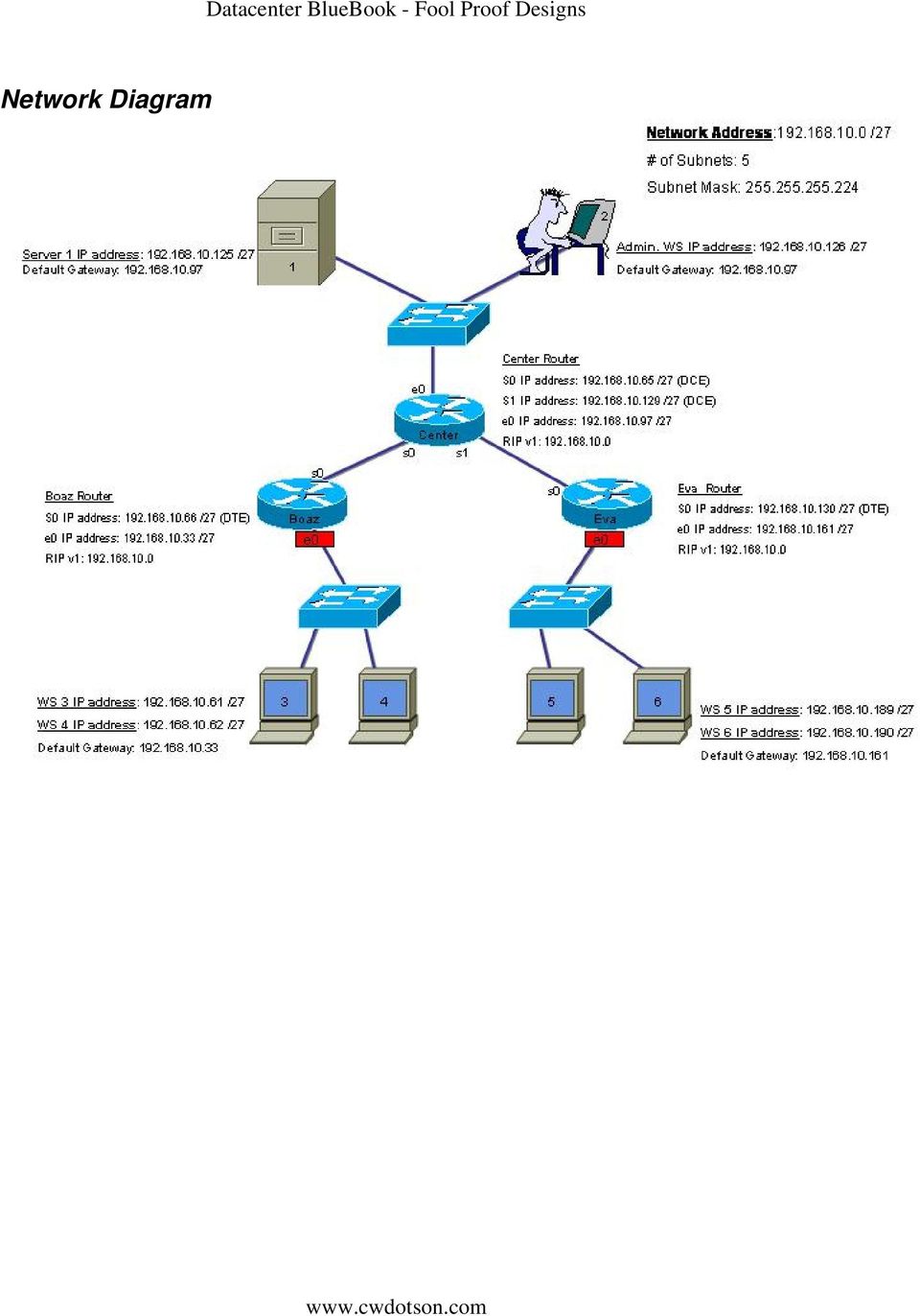
6 Table 1: Network/Host Information (Basic information) Router Designation Router Name Enable Secret VTY/Console Password Routing Protocol Routing Statements Router 1 Center class cisco RIP v Router 2 Boaz class cisco RIP v Router 3 Eva class cisco RIP v Router Ethrnt 0 IP Ethrnt 1 IP Serial 0 IP Serial 1 IP Subnet Mask Designation Address Addr. Address Address Router xxx.xxx.xxx.xxx Router xxx.xxx.xxx.xxx xxx.xxx.xxx.xxx Router xxx.xxx.xxx.xxx xxx.xxx.xxx.xxx Host S/N IP Address Subnet Mask Gateway Fileserver WS2(admin) WS WS WS WS Device Router1 Router2 Router3 Fileserver1 WS2(admin) WS3 WS4 WS5 OS (Vers.) MAC Address XP XP XP XP XP WS6 XP
 192.168.10.126 255.")
7 IP Address Worksheet Net Zero: /27 Net-Zero b-cast: NetMask/CIDR: Subnet # First host Last host Broadcast Subnetting Worksheet: CIDR /27 ( ) Requirements: Network must provide for 5 subnets. No more than 30 hosts per subnet. Use a Class C network address, RIP v1 (classful routing). Results: CIDR = /27 (subnet mask ); Blocksize = 32; Provides up to 6 valid subnets, (only the first 5 subnets are assigned/utilized). 30 nodes (interfaces) per subnet (maximum).
. Results: CIDR = /27 (subnet mask 255.255.255.224); Blocksize = 32; Provides up to 6 valid subnets, (only the first 5 subnets are assigned/utilized).")
8 VLSM Worksheet 0 Network 0: Sub-Network 1: Sub-Network 2: Sub-Network 3: Sub-Network 4: Sub-Network 5:

9 Sub-Network 6: (un-used) Sub-Network 7: (invalid)
 228 232")
10 Configuration Worksheet (detail) Hostname Boaz Center Eva Router Type (Model #) Router S/N Console / Aux Password cisco / cisco cisco / cisco cisco / cisco Secret Password class class class VTY 0 4 Password Cisco cisco cisco Net Mask Serial 0 IP Address Serial 1 IP Address n/a n/a Serial 0 Clock Rate DTE DCE/64000 DTE Serial 1 Clock Rate N/A DCE/64000 N/A e0 IP Address e1 IP Address n/a n/a n/a Enable interfaces no shut no shut no shut Add Routing Protocol RIP (v1) RIP (v1) RIP (v1) Add Network Statements Host Table: Routers/Hosts Message of the day Center, WS3, WS4, Eva, WS5, WS6, WS2 Warning: You have entered a Restricted access area. **** Please log off!! Boaz, WS3, WS4, Eva, WS5, WS6, WS2 Warning: You have entered a Restricted access area. **** Please log off!! Center, Boaz, WS3, WS4, WS5, WS6, WS2 Warning: You have entered a Restricted access area. **** Please log off!! Ser 0 Description WAN link-center (CKT#123) WAN link - Boaz (CKT#123) Ser 1 Description N/A WAN link-eva (CKT#456) Fa 0 Description Boaz-LAN Center-LAN Eva-LAN Fa 1 Description N/A N/A N/A WAN link-center (CKT#456) N/A
 RIP (v1) RIP (v1) Add Network Statements 192.168.10.0 192.168.10.0 192.168.10.0 Host Table: Routers/Hosts Message of the day Center, WS3, WS4, Eva, WS5, WS6, WS2 Warning: You have entered a Restricted access area.")
11 Initial (Baseline) Configuration Verification - Checklist #1 Prior to adding ACL s to the initial configuration, it is important to verify the baseline configuration has been successfully achieved. The checklist, below, includes a list of key tests (and the expected results) to be conducted. A similar checklist of tests will be conducted, later, and after the ACL s have been applied to the network. At this time, verify the baseline configuration has been achieved, according to the following checklist. Record the results of each test, in the space provided. Successful? Test/Condition telnet Boaz to Eva telnet WS4 to Eva telnet WS5 to Boaz telnet WS2 to Boaz telnet WS2 to Eva ping WS5 to Fileserver 1 ping WS3 to Fileserver 1 ping WS3 to WS4 ping WS5 to WS6 ping WS3 to WS5 ping WS2 to WS5 ping WS2 to WS3 ping Eva to WS3 ping Boaz to WS5 Expected Result ACL Lists and Statements Configuration notes: Prior to applying any ACL statements, perform the following steps: First, verify all network devices can successfully ping each of the other devices, for the entire network. This includes all routers, workstations, and servers (each device successfully pings the other device, ensuring fully functioning (i.e., full connectivity) between all networks, interfaces, and devices). Verify the baseline configuration has been achieved (see previous checklist). Next, copy this initial configuration to NVRAM (copy run start). Next, make a backup of each configuration of each router (without ACL s applied). This is the Fall-Back configuration, for later (i.e. if this process fails or an incorrect configuration is applied, re-use this FB configuration). For example, create a sample backup, with the filename: Router-Center-FB-cfg- 1.0.txt. Then, save this backup to fileserver, CDROM and/or diskette.

12 Admin. WS Tests: Perform tests from the Admin Workstation to each node, especially nodes that exist on ACL-protected networks. o For example, verify Admin station (WS2) can successfully ping (and/or telnet, if enabled) to WS3, WS4, WS5, and WS6. o Verify all customer and admin. applications successfully function, such as those that send/receive data and files between the fileserver (and/or the Admin Workstation) and all other hosts (from WS2 to/from all subnetworks), as required. After identifying the ACL statements required for each router and interface (including direction each ACL is to be applied), follow these instructions as you begin to apply them to each router. Remote administration is important, since it is not possible to physically maintain equipment in remote offices (Boaz and Eva). Prior to applying a new (i.e., untested) ACL to an interface, it is advisable to, first, execute a reload in 50 command at the router (PRIV mode) prompt. This will reload the NVRAM configuration, in case the ACL results in total, remote lock-out. After 50 seconds, or so, you will be able to re-connect, since the router will have returned to its Fall-Back configuration. o NOTE: If the ACL works, then you ll need to disable the reload before the 50 second reload-timer has expired. Using a text editor to store each statement, create ACL s for each router (i.e., Router- Center-ACL-cfg-1.0.txt). Enter each ACL statement into these files, and save to disk. To configure each router, copy/paste the ACL statements from the file into the HyperTerminal session of each router, as appropriate. In this manner, configure each router to use the ACL that has been created specifically for it (i.e., unless otherwise noted, do not use the Center router s ACL on the Eva, or Boaz router s, since each ACL is unique to each sub-network). Finally, after all customer tests (including the Configuration Test Plan, below) have been successfully completed, save the configuration to NVRAM (i.e., copy run start), and make copies of all disk files (that is, making copies of all the running-configuration on each router using HyperTerminal to capture/record, and cut/paste into a text file named Router-Center-cfg-1.0.txt), plus all ACL s.(i.e., text files), plus the configuration worksheets, Configuration Management information, and Network Diagram: Save all configuration information and files to a secure system, or PC, such as the Administrative WorkStation, and/or the Fileserver (using a password protected directory, with restricted read, write, or execute access permissions). Also, create an additional backup of these materials using a CD-R, and 3.5 floppy diskette (write-protected, afterwards!), and store them in a secure, cool, dry place. It is advisable to create a 3 rd set of backup media, stored in a similar manner, but in an off-site location, for use during Disaster/Recovery operations (in the event of flooding, fire, earthquake, etc.).

13 ACL s 100 (inbound) The following Extended ACL statements restrict access between nodes, as per the requirements of this case study. For this study, ACL s are to be applied to the e0 interface (inbound) on both the Boaz and Eva routers. Since Boaz and Eva are configured as per the Network Diagram, the same ACL is to be applied to each router, (i.e., ACL 100, applied to their inbound, e0 interfaces), as described in the table below. Please note: The ACL number is local-only, and is not a global value. If additional traffic/applications shall be permitted between these WS s, then additional ACL s (and/or statements) must be created/applied. If additional security is required, ACL s can be applied to Center, thereby limiting traffic destined for the Center LAN ( network). At this time, additional restrictions are unnecessary, since the Administrator is the primary user on the Center-LAN and is, also, responsible for maintaining the entire network. Benefits: This is an Extended ACL created as a security standard throughout the network (in this case, standard implies it is an identical ACL used on all remote routers, Boaz and Eva), which minimizes complexity, and simplifies CM, test, and management procedures. Furthermore, only the remote routers are affected by these ACL s, thereby minimizing overall performance impact on the network by a) limiting the number of ACL s (and statements) to be applied to each packet, and b) limiting the amount of unwanted traffic from traversing the WAN (serial links). ACL 100: e0 inbound (Boaz and Eva) Statements access-list 100 permit / ip any host / access-list 100 permit / icmp any any echo-reply ip access-group 100 in Descriptions Permit any host on LAN access to fileserver 1 Allow successful ping originating from any host on external network to return to source Apply ACL to LAN interface (e0, incoming) Configuration Test Plan (basic connectivity/security using ACL s) The access control (security) goals for this network include the following conditions: WorkStation 2 (WS2) and File Server 1 are on the Management Network, and are able to access all other network devices (routers, workstations, server). Unless noted otherwise, all WorkStations (WS) on the Boaz LAN shall be permitted to access to File Server 1 only, and they are NOT permitted access

14 outside their own LAN. For example, the WS s on the Boaz LAN can access fileserver 1 and the WS s connected to their own Boaz LAN, but they are not allowed to access any WS s connected to other (external) networks or LAN s outside the Boaz LAN. Unless noted otherwise, all WorkStations (WS) on the Eva LAN shall be permitted to access to File Server 1 only, and they are NOT permitted access outside their own LAN. For example, the WS s on the Eva LAN can access fileserver 1 and the WS s connected to their own Eva LAN, but they are not allowed to access any WS s connected to other (external) networks or LAN s outside the Eva LAN. The Center, Eva, and Boaz routers are permitted to access to any device on the network, including all routers, workstations, and servers. WS s on the Boaz LAN may access each other. WS s on the Eva LAN may access each other. Monitoring the Network After each component has been configured and the procedures (and configurations) documented, as outlined above (and according to the Network Diagram), the following tests should be conducted to verify the correct configuration has been achieved (and is maintained) for each node on the network. Place a checkmark next to each line item, to indicate the test was successful, according to the instructions provided on each line. The following tests and commands should be conducted as part of routine and/or preventative maintenance procedures. Verify each test achieves the expected result. Periodically, verify the Configuration Management information has not changed, and the CM data is still valid, and is running on each router and system in the network. The CM Worksheets, below, document the validated configuration. In the future, testing should be conducted to ensure the configuration has not been modified, and the configuration adheres to the validated CM information contained in this document. Any changes/modifications made to any network component must be re-tested (i.e. re-validated according to the testing guidelines listed herein), and all changes documented using the CM worksheets, Network Diagram, and Checklists. Because the network is vital to the company (i.e., business-critical) it is recommended that Change Management policies and procedures be defined and implemented, and strictly adhered to even for relatively minor changes to any network component, or device.
 on the Eva LAN shall be permitted to access to File Server 1 only, and they are NOT permitted access For example, the WS s on the Eva LAN can access")
15 Validate the ACL Configuration - Checklist#2 Successful? Test/Condition telnet Boaz to Eva telnet WS4 to Eva telnet WS5 to Boaz telnet WS2 to Boaz telnet WS2 to Eva ping WS5 to Fileserver 1 ping WS3 to Fileserver 1 ping WS3 to WS4 ping WS5 to WS6 ping WS3 to WS5 ping WS2 to WS5 ping WS2 to WS3 ping Eva to WS3 ping Boaz to WS5 Expected Result unreachable unreachable unreachable CM Documentation (command outputs from validated configuration) Commands (outputs) Boaz Center Eva show cdp neighbors show ip route show ip protocol show ip interface brief show version show hosts show startup-config show running-config Note: For specific configuration data, refer to previous worksheets, tables and descriptions (i.e., interfaces, directions, protocols, etc.) Security Management Documentation (command outputs from validated configuration) Commands (outputs) Boaz Center Eva show ip interface show ip access lists Show access-lists Note: For specific configuration data, refer to previous worksheets, tables and descriptions (i.e., interfaces, directions, protocols, etc.)
 Boaz Center Eva show cdp neighbors show ip route show ip protocol show ip interface brief show version show hosts show startup-config show running-config Note: For specific configuration")
Lab 5.5.3 Developing ACLs to Implement Firewall Rule Sets
 Lab 5.5.3 Developing ACLs to Implement Firewall Rule Sets All contents are Copyright 1992 2007 Cisco Systems, Inc. All rights reserved. This document is Cisco Public Information. Page 1 of 8 Device Interface
Note: This case study utilizes Packet Tracer. Please see the Chapter 5 Packet Tracer file located in Supplemental Materials.
 Note: This case study utilizes Packet Tracer. Please see the Chapter 5 Packet Tracer file located in Supplemental Materials. CHAPTER 5 OBJECTIVES Configure a router with an initial configuration. Use the
Lab 7.2.9 Load Balancing Across Multiple Paths
 Lab 7.2.9 Load Balancing Across Multiple Paths Objective Configure Load balance across multiple paths. Observe the load balancing process. Background/Preparation Cable a network similar to the one in the
Objectives. Router as a Computer. Router components and their functions. Router components and their functions
 2007 Cisco Systems, Inc. All rights reserved. Cisco Public Objectives Introduction to Routing and Packet Forwarding Routing Protocols and Concepts Chapter 1 Identify a router as a computer with an OS and
Lab 1.2.3 Review of Basic Router Configuration with RIP. Objective. Background / Preparation. General Configuration Tips
 Lab 1.2.3 Review of Basic Router Configuration with RIP Objective Cable and configure workstations and routers Setup IP addressing scheme using Class B networks Configure Routing Information Protocol (RIP)
Lab 3.1.2 Creating a Logical Network Diagram
 Lab 3.1.2 Creating a Logical Network Diagram Objectives Use router and switch commands to obtain information about an existing network. Use Cisco Network Assistant to obtain information about an existing
Lab 4.2.4 Advanced Telnet Operations
 Lab 4.2.4 Advanced Telnet Operations Objective Use the telnet command to remotely access other routers. Verify that the application layer between the source and the destination is working properly. Suspend
Lab 5.3.5 Configuring Basic Router Settings with the Cisco IOS CLI
 Lab 5.3.5 Configuring Basic Router Settings with the Cisco IOS CLI Device Host Name Interface IP address Subnet mask R1 R1 Serial 0/0/0 (DCE) 172.17.0.1 255.255.0.0 FastEthernet 0/0 172.16.0.1 255.255.0.0
LAB Configuring NAT. Objective. Background/Preparation
 LAB Configuring NAT Objective Configure a router to use network address translation (NAT) to convert internal IP addresses, typically private addresses, into outside public addresses. Configure static
3.1 Connecting to a Router and Basic Configuration
 3.1 Connecting to a Router and Basic Configuration Objective This lab will focus on the ability to connect a PC to a router in order to establish a console session and observe the user interface. A console
Lab 4.5.4 Diagramming External Traffic Flows
 Lab 4.5.4 Diagramming External Traffic Flows Device Designation Device Name Address Subnet Mask Discovery Server Business Services 172.17.1.1 255.255.0.0 R1 R2 R3 FC-CPE-1 FC-CPE-2 ISP Fa0/1 172.17.0.1
Lab 1.4.1 Introductory Lab 1 - Getting Started and Building Start.txt
 Lab 1.4.1 Introductory Lab 1 - Getting Started and Building Start.txt Objective This lab may introduce new CCNP lab equipment and certain IOS features. This introductory activity also describes how to
Packet Tracer 3 Lab VLSM 2 Solution
 Packet Tracer 3 Lab VLSM 2 Solution Objective Create a simulated network topology using Packet Tracer Design an IP addressing scheme using a Class B subnetwork address and VLSM Apply IP addresses to the
Lab 2 - Basic Router Configuration
 CS326 Fall 2001 Room: PAI 5.48 Name: Lab 2 - Basic Router Configuration In this lab you will learn: the various configuration modes of Cisco 2621 routers how to set up IP addresses for such routers how
PT Activity 8.1.2: Network Discovery and Documentation Topology Diagram
 Topology Diagram All contents are Copyright 1992 2007 Cisco Systems, Inc. All rights reserved. This document is Cisco Public Information. Page 1 of 6 Addressing Table Device Interface IP Address Subnet
Lab 1.5.1 Introductory Lab 1 Getting Started and Building Start.txt
 Lab 1.5.1 Introductory Lab 1 Getting Started and Building Start.txt Objective This lab will introduce to the student the CCNP lab equipment and certain IOS features that might be new. This introductory
Lab 2.3.2 Configuring OSPF with Loopback Addresses
 Lab 2.3.2 Configuring OSPF with Loopback Addresses Objective Configure routers with a Class C IP addressing scheme. Observe the election process for designated routers (DR) and backup designated routers
Lab: Basic Router Configuration
 Topology Diagram Addressing Table Device Interface IP Address Subnet Mask Def. Gateway R1 Fa0/0 192.168.1.1 255.255.255.0 N/A S0/0/0 192.168.2.1 255.255.255.0 N/A R2 Fa0/0 192.168.3.1 255.255.255.0 N/A
CCNA Access List Sim
 1 P a g e CCNA Access List Sim Question An administrator is trying to ping and telnet from Switch to Router with the results shown below: Switch> Switch> ping 10.4.4.3 Type escape sequence to abort. Sending
Lab 5.3.8 Configuring PAT with SDM and Static NAT using Cisco IOS Commands
 Lab 5.3.8 Configuring PAT with SDM and Static NAT using Cisco IOS Commands Device Host Name Interface IP Address Subnet Mask R1 CustomerRouter Serial 0/0/0 (DTE) 209.165.200.225 255.255.255.224 Fast Ethernet
Lab 4.1.4 Creating a Network Map using CDP Instructor Version 2500
 Lab 4.1.4 Creating a Network Map using CDP Instructor Version 2500 Objective Use Cisco Discovery Protocol (CDP) commands to get information about neighboring network devices. Background/Preparation CDP
CCNA Exploration 4.0: (II) Routing Protocols and Concepts. Chapter 1: Introduction to Routing and Packet Forwarding
 Routing Protocols and Concepts. Chapter 1: Introduction to Routing and Packet Forwarding") Http://elmaestrodelared.blogspot.com CCNA Exploration 4.0: (II) Routing Protocols and Concepts Chapter 1: Introduction to Routing and Packet Forwarding 1. If a router cannot find a valid configuration
Http://elmaestrodelared.blogspot.com CCNA Exploration 4.0: (II) Routing Protocols and Concepts Chapter 1: Introduction to Routing and Packet Forwarding 1. If a router cannot find a valid configuration
Lab 8.4.3a Managing Cisco IOS Images with TFTP
 Lab 8.4.3a Managing Cisco IOS Images with TFTP Host Device Name Interface IP Address Subnet Mask R1 R1 Fast Ethernet 0/0 172.17.0.1 255.255.0.0 Objectives Analyze the Cisco IOS image and router flash memory.
Lab 5.3.9b Managing Router Configuration Files Using TFTP
 Lab 5.3.9b Managing Router Configuration Files Using TFTP Device Host Name Interface IP Address Subnet Mask R1 R1 Fast Ethernet 0/0 172.17.0.1 255.255.0.0 Objectives Download and install TFTP server software.
Applicazioni Telematiche
 Angelo Coiro Laboratorio Applicazioni Telematiche L emulatore Packet Tracer Packet Tracer Cisco Packet Tracer is an academic software that allows to emulate Cisco devices Packet Tracer can be used for
Introduction to Routing and Packet Forwarding. Routing Protocols and Concepts Chapter 1
 Introduction to Routing and Packet Forwarding Routing Protocols and Concepts Chapter 1 1 1 Objectives Identify a router as a computer with an OS and hardware designed for the routing process. Demonstrate
Lab 7.2.9 Load Balancing Across Multiple Paths Instructor Version 2500
 Lab 7.2.9 Load Balancing Across Multiple Paths Instructor Version 2500 Objective onfigure Load balance across multiple paths. Observe the load balancing process. Background/Preparation able a network similar
Lab 5.3.7 Configuring DHCP with SDM and the Cisco IOS CLI
 Lab 5.3.7 Configuring DHCP with SDM and the Cisco IOS CLI Device Host Name Interface IP Address Subnet Mask R1 Customer Serial 0/0/1 (DTE) 209.165.200.225 255.255.255.224 Fast Ethernet 0/0 192.168.1.1
Procedure: You can find the problem sheet on Drive D: of the lab PCs. 1. IP address for this host computer 2. Subnet mask 3. Default gateway address
 Objectives University of Jordan Faculty of Engineering & Technology Computer Engineering Department Computer Networks Laboratory 907528 Lab.4 Basic Network Operation and Troubleshooting 1. To become familiar
Router Lab Reference Guide
 Router Lab Reference Guide 1 PURPOSE AND GOALS The routing lab allows testing different IP-related protocols and solutions in a close to live environment. You can learn how to configure Cisco routers and
Lab 8.3.13 Configure Cisco IOS Firewall CBAC
 Lab 8.3.13 Configure Cisco IOS Firewall CBAC Objective Scenario Topology In this lab, the students will complete the following tasks: Configure a simple firewall including CBAC using the Security Device
Sample Configuration Using the ip nat outside source static
 Sample Configuration Using the ip nat outside source static Table of Contents Sample Configuration Using the ip nat outside source static Command...1 Introduction...1 Before You Begin...1 Conventions...1
Skills Assessment Student Training Exam
 Skills Assessment Student Training Exam Topology Assessment Objectives Part 1: Initialize Devices (8 points, 5 minutes) Part 2: Configure Device Basic Settings (28 points, 30 minutes) Part 3: Configure
CCNA 2 Chapter 5. Managing Cisco IOS Software
 1 CCNA 2 Chapter 5 Managing Cisco IOS Software The default source for Cisco IOS Software depends on the hardware platform; most commonly, though, the router looks to the configuration commands that are
Lab 4.1.2 Characterizing Network Applications
 Lab 4.1.2 Characterizing Network Applications Objective Device Designation Device Name Address Subnet Mask Discovery Server Business Services 172.17.1.1 255.255.0.0 R1 FC-CPE-1 Fa0/1 172.17.0.1 Fa0/0 10.0.0.1
Lab 5.3.5 Configuring Basic Router Settings with the Cisco IOS CLI
 Lab 5.3.5 Configuring Basic Router Settings with the Cisco IOS CLI Device Host Name Interface IP Address Subnet Mask R1 R1 Serial 0/0/0 (DCE) 172.17.0.1 255.255.0.0 FastEthernet 0/0 172.16.0.1 255.255.0.0
Router and Routing Basics
 Router and Routing Basics Malin Bornhager Halmstad University Session Number 2002, Svenska-CNAP Halmstad University 1 Routing Protocols and Concepts CCNA2 Routing and packet forwarding Static routing Dynamic
Chapter 8 Lab B: Configuring a Remote Access VPN Server and Client
 Chapter 8 Lab B: Configuring a Remote Access VPN Server and Client Topology Note: ISR G2 devices have Gigabit Ethernet interfaces instead of FastEthernet Interfaces. All contents are Copyright 1992 2012
CCT vs. CCENT Skill Set Comparison
 Operation of IP Data Networks Recognize the purpose and functions of various network devices such as Routers, Switches, Bridges and Hubs Select the components required to meet a given network specification
PT Activity: Configure Cisco Routers for Syslog, NTP, and SSH Operations
 PT Activity: Configure Cisco Routers for Syslog, NTP, and SSH Operations Instructor Version Topology Diagram Addressing Table Device Interface IP Address Subnet Mask Default Gateway Switch Port R1 FA0/1
Lab 4.5.2 Diagramming Intranet Traffic Flows
 Lab 4.5.2 Diagramming Intranet Traffic Flows Objective Device Designation Device Name Address Subnet Mask Discovery Server Business Services 172.17.1.1 255.255.0.0 R1 FC-CPE-1 Fa0/1 172.17.0.1 Fa0/0 10.0.0.1
Device Interface IP Address Subnet Mask Default Gateway
 Felix Rohrer Topology Diagram Addressing Table Device Interface IP Address Subnet Mask Default Gateway S1 VLAN 99 192.168.99.11 255.255.255.0 192.168.99.1 S2 VLAN 99 192.168.99.12 255.255.255.0 192.168.99.1
You can probably work with decimal. binary numbers needed by the. Working with binary numbers is time- consuming & error-prone.
 IP Addressing & Subnetting Made Easy Working with IP Addresses Introduction You can probably work with decimal numbers much easier than with the binary numbers needed by the computer. Working with binary
How To Block On A Network With A Group Control On A Router On A Linux Box On A Pc Or Ip Access Group On A Pnet 2 On A 2G Router On An Ip Access-Group On A Ip Ip-Control On A Net
 Using Access-groups to Block/Allow Traffic in AOS When setting up an AOS unit, it is important to control which traffic is allowed in and out. In many cases, the built-in AOS firewall is the most efficient
Lab 10.3.5a Basic Subnetting
 Lab 10.3.5a Basic Subnetting Objective How to identify reasons to use a subnet mask How to distinguish between a default subnet mask and a custom subnet mask What given requirements determine the subnet
Lab 4.5.3 Diagramming Traffic Flows to and from Remote Sites
 Lab 4.5.3 Diagramming Traffic Flows to and from Remote Sites Objective Device Designation Device Name Address Subnet Mask Discovery Server Business Services 172.17.1.1 255.255.0.0 R1 R2 R3 FC-CPE-1 FC-CPE-2
RIPv2 with Variable Length Subnet Masks (VLSMs)
") RIPv2 with Variable Length Subnet Masks (VLSMs) This chapter will discuss the RIPv2 routing process. This is an important subject to understand as it pertains to all routers and configurations that use
RIPv2 with Variable Length Subnet Masks (VLSMs) This chapter will discuss the RIPv2 routing process. This is an important subject to understand as it pertains to all routers and configurations that use
Firewall Stateful Inspection of ICMP
 The feature addresses the limitation of qualifying Internet Control Management Protocol (ICMP) messages into either a malicious or benign category by allowing the Cisco IOS firewall to use stateful inspection
Part A:Background/Preparation
 Lab no 1 PC Network TCP/IP Configuration In this lab we will learn about Computer Networks Configuration Introduction to IP addressing Identify tools used for discovering a computer s network configuration
Chapter 1 Introduction to Network Maintenance Objectives
 Introduction to Network Maintenance Objectives Describe network maintenance tasks Explain the difference between proactive and reactive network maintenance. Describe well-known network maintenance models.
Lab 3.5.1: Basic VLAN Configuration (Instructor Version)
") (Instructor Version) Topology Diagram Addressing Table Device (Hostname) Interface IP Address Subnet Mask Default Gateway S1 VLAN 99 172.17.99.11 255.255.255.0 N/A S2 VLAN 99 172.17.99.12 255.255.255.0
(Instructor Version) Topology Diagram Addressing Table Device (Hostname) Interface IP Address Subnet Mask Default Gateway S1 VLAN 99 172.17.99.11 255.255.255.0 N/A S2 VLAN 99 172.17.99.12 255.255.255.0
Sample Configuration Using the ip nat outside source list C
 Sample Configuration Using the ip nat outside source list C Table of Contents Sample Configuration Using the ip nat outside source list Command...1 Introduction...1 Before You Begin...1 Conventions...1
Connect the Host to attach to Fast Ethernet switch port Fa0/2. Configure the host as shown in the topology diagram above.
 Lab 1.2.2 Capturing and Analyzing Network Traffic Host Name IP Address Fa0/0 Subnet Mask IP Address S0/0/0 Subnet Mask Default Gateway RouterA 172.17.0.1 255.255.0.0 192.168.1.1 (DCE) 255.255.255.0 N/A
Objectives. Background. Required Resources. CCNA Security
 Chapter 8 Lab B, Configuring a Remote Access VPN Server and Client Topology IP Addressing Table Device Interface IP Address Subnet Mask Default Gateway Switch Port R1 FA0/1 192.168.1.1 255.255.255.0 N/A
Troubleshooting the Firewall Services Module
 25 CHAPTER This chapter describes how to troubleshoot the FWSM, and includes the following sections: Testing Your Configuration, page 25-1 Reloading the FWSM, page 25-6 Performing Password Recovery, page
Source net: 200.1.1.0 Destination net: 200.1.2.0 Subnet mask: 255.255.255.0 Subnet mask: 255.255.255.0. Router Hub
 then to a router. Remember that with a Class C network address, the first 3 octets, or 24 bits, are assigned as the network address. So, these are two different Class C networks. This leaves one octet,
Lab 3.8.3 Configure Cisco IOS Firewall CBAC on a Cisco Router
 Lab 3.8.3 Configure Cisco IOS Firewall CBAC on a Cisco Router Objective Scenario Topology Estimated Time: 35 minutes Number of Team Members: Two teams with four students per team In this lab exercise,
Cisco Configuring Commonly Used IP ACLs
 Table of Contents Configuring Commonly Used IP ACLs...1 Introduction...1 Prerequisites...2 Hardware and Software Versions...3 Configuration Examples...3 Allow a Select Host to Access the Network...3 Allow
Course Syllabus. Fundamentals of Windows Server 2008 Network and Applications Infrastructure. Key Data. Audience. Prerequisites. At Course Completion
 Key Data Product #: 3380 Course #: 6420A Number of Days: 5 Format: Certification Exams: Instructor-Led None This course syllabus should be used to determine whether the course is appropriate for the students,
1 Data information is sent onto the network cable using which of the following? A Communication protocol B Data packet
 Review questions 1 Data information is sent onto the network cable using which of the following? A Communication protocol B Data packet C Media access method D Packages 2 To which TCP/IP architecture layer
Lab 6.2.3 Managing the MAC Address Table
 Lab 6.2.3 Managing the MAC Address Table Objective Create a basic switch configuration. Manage the switch MAC table. Background/Preparation Cable a network similar to the one in the diagram. The configuration
Lab 10.4.1 IP Addressing Overview
 Lab 10.4.1 IP ing Overview Estimated time: 30 min. Objectives: Background: This lab will focus on your ability to accomplish the following tasks: Name the five different classes of IP addresses Describe
Lab 8.3.1.2 Configure Basic AP Security through IOS CLI
 Lab 8.3.1.2 Configure Basic AP Security through IOS CLI Estimated Time: 30 minutes Number of Team Members: Students will work in teams of two. Objective In this lab, the student will learn the following
ASA 8.3 and Later: Mail (SMTP) Server Access on Inside Network Configuration Example
 Server Access on Inside Network Configuration Example") ASA 8.3 and Later: Mail (SMTP) Server Access on Inside Network Configuration Example Document ID: 113336 Contents Introduction Prerequisites Requirements Components Used Conventions Configure Network Diagram
ASA 8.3 and Later: Mail (SMTP) Server Access on Inside Network Configuration Example Document ID: 113336 Contents Introduction Prerequisites Requirements Components Used Conventions Configure Network Diagram
Computer Networks I Laboratory Exercise 1
 Computer Networks I Laboratory Exercise 1 The lab is divided into two parts where the first part is a basic PC network TCP/IP configuration and connection to the Internet. The second part is building a
Lab 3 Routing Information Protocol (RIPv1) on a Cisco Router Network
 on a Cisco Router Network") Lab 3 Routing Information Protocol (RIPv1) on a Cisco Router Network CMPE 150 Fall 2005 Introduction Today you are going to be thrown into using Cisco s Internetwork Operating System (IOS) to configure
Lab 3 Routing Information Protocol (RIPv1) on a Cisco Router Network CMPE 150 Fall 2005 Introduction Today you are going to be thrown into using Cisco s Internetwork Operating System (IOS) to configure
- The PIX OS Command-Line Interface -
 1 PIX OS Versions - The PIX OS Command-Line Interface - The operating system for Cisco PIX/ASA firewalls is known as the PIX OS. Because the PIX product line was acquired and not originally developed by
Chapter 3: IP Addressing and VLSM
 Chapter 3: IP Addressing and VLSM QUESTION 54 What is the principle reason to use a private IP address on an internal network? A. Subnet strategy for private companies. B. Manage and scale the growth of
Prestige 310. Cable/xDSL Modem Sharing Router. User's Guide Supplement
 Prestige 310 Cable/xDSL Modem Sharing Router User's Guide Supplement Domain Name Support Enhanced WAN Setup Remote Node Support PPPoE Support Enhanced Unix Syslog Setup Firmware and Configuration Files
During this lab time you will configure the routing protocol OSPF with IPv4 addresses.
 Lab 2: OSPF During this lab time you will configure the routing protocol OSPF with IPv4 addresses. It is your responsibility to create an appropriate IPv4 subnet plan and address plan. To ensure a timely
Welcome to Todd Lammle s CCNA Bootcamp
 Welcome to Todd Lammle s CCNA Bootcamp Todd Lammle Cisco Authorized CCNA Bootcamps are now available, delivered by CCSI instructor, and popular Sybex author Todd Lammle. Todd Lammle CCNA Training Boot
Procedure: You can find the problem sheet on Drive D: of the lab PCs. Part 1: Router & Switch
 University of Jordan Faculty of Engineering & Technology Computer Engineering Department Computer Networks Laboratory 907528 Lab. 2 Network Devices & Packet Tracer Objectives 1. To become familiar with
100-101: Interconnecting Cisco Networking Devices Part 1 v2.0 (ICND1)
") 100-101: Interconnecting Cisco Networking Devices Part 1 v2.0 (ICND1) Course Overview This course provides students with the knowledge and skills to implement and support a small switched and routed network.
100-101: Interconnecting Cisco Networking Devices Part 1 v2.0 (ICND1) Course Overview This course provides students with the knowledge and skills to implement and support a small switched and routed network.
Configuring a Leased Line
 CHAPTER 4 Configuring a Leased Line The configuration in this chapter describes how to configure a Cisco 1700 router for IP and IPX over a synchronous serial line. Before You Begin The configuration in
Networking Guide Redwood Manager 3.0 August 2013
 Networking Guide Redwood Manager 3.0 August 2013 Table of Contents 1 Introduction... 3 1.1 IP Addresses... 3 1.1.1 Static vs. DHCP... 3 1.2 Required Ports... 4 2 Adding the Redwood Engine to the Network...
Network Simulator Lab Study Plan
 The CCNA 640-802 Network Simulator has 300 lab exercises, organized both by type (Skill Builder, Configuration Scenario, Troubleshooting Scenario, and Subnetting Exercise) and by major topic within each
Configuring the PIX Firewall with PDM
 Configuring the PIX Firewall with PDM Objectives In this lab exercise you will complete the following tasks: Install PDM Configure inside to outside access through your PIX Firewall using PDM Configure
Chapter 3 Using Access Control Lists (ACLs)
") Chapter 3 Using Access Control Lists (ACLs) Access control lists (ACLs) enable you to permit or deny packets based on source and destination IP address, IP protocol information, or TCP or UDP protocol
Chapter 3 Using Access Control Lists (ACLs) Access control lists (ACLs) enable you to permit or deny packets based on source and destination IP address, IP protocol information, or TCP or UDP protocol
Troubleshooting the Firewall Services Module
 CHAPTER 25 This chapter describes how to troubleshoot the FWSM, and includes the following sections: Testing Your Configuration, page 25-1 Reloading the FWSM, page 25-6 Performing Password Recovery, page
Basic Software Configuration Using the Cisco IOS Command-Line Interface
 Basic Software Configuration Using the Cisco IOS Command-Line Interface This document describes how to use the Cisco IOS command-line interface (CLI) to perform a basic software configuration for your
Specialized Programme on Internetworking Design and LAN WAN Administration
 Specialized Programme on Internetworking Design and LAN WAN Administration A. NAME OF INSTITUTE Centre For Development of Advanced Computing B. NAME/TITLE OF THE COURSE C. COURSE DATES WITH DURATION IN
Lab - Using IOS CLI with Switch MAC Address Tables
 Topology Addressing Table Objectives Device Interface IP Address Subnet Mask Default Gateway R1 G0/1 192.168.1.1 255.255.255.0 N/A S1 VLAN 1 192.168.1.11 255.255.255.0 192.168.1.1 S2 VLAN 1 192.168.1.12
School of Information Technology and Engineering (SITE) CEG 4395: Computer Network Management. Lab 4: Remote Monitoring (RMON) Operations
 CEG 4395: Computer Network Management. Lab 4: Remote Monitoring (RMON) Operations") School of Information Technology and Engineering (SITE) CEG 4395: Computer Network Management Lab 4: Remote Monitoring (RMON) Operations Objective To become familiar with basic RMON operations, alarms,
School of Information Technology and Engineering (SITE) CEG 4395: Computer Network Management Lab 4: Remote Monitoring (RMON) Operations Objective To become familiar with basic RMON operations, alarms,
ICND1-100-101 IOS CLI Study Guide (CCENT)
") ICND1-100-101 IOS CLI Study Guide (CCENT) Hostname: 2. hostname SW1 SWITCH CONFIGURATION Mgmt IP: 2. interface vlan 1 3. ip address 10.0.0.2 4. no shut Gateway: 2. ip default-gateway 10.0.0.1 Local User/Pwd:
ICND1-100-101 IOS CLI Study Guide (CCENT) Hostname: 2. hostname SW1 SWITCH CONFIGURATION Mgmt IP: 2. interface vlan 1 3. ip address 10.0.0.2 4. no shut Gateway: 2. ip default-gateway 10.0.0.1 Local User/Pwd:
The Cisco IOS Firewall feature set is supported on the following platforms: Cisco 2600 series Cisco 3600 series
 Cisco IOS Firewall Feature Set Feature Summary The Cisco IOS Firewall feature set is available in Cisco IOS Release 12.0. This document includes information that is new in Cisco IOS Release 12.0(1)T, including
Security and Access Control Lists (ACLs)
") Security and Access Control Lists (ACLs) Malin Bornhager Halmstad University Session Number 2002, Svenska-CNAP Halmstad University 1 Objectives Security Threats Access Control List Fundamentals Access
Security and Access Control Lists (ACLs) Malin Bornhager Halmstad University Session Number 2002, Svenska-CNAP Halmstad University 1 Objectives Security Threats Access Control List Fundamentals Access
VLSM & IP ADDRESSING EXAMPLE QUESTIONS with answers;
 VLSM & IP ADDRESSING EXAMPLE QUESTIONS with answers; 1 Given the network address of 112.44.0.0 and the network mask of 255.255.0.0 Would the two stations with addresses 112.44.22.19/16 and 112.44.23.2/16
Interconnecting Cisco Network Devices 1 Course, Class Outline
 www.etidaho.com (208) 327-0768 Interconnecting Cisco Network Devices 1 Course, Class Outline 5 Days Interconnecting Cisco Networking Devices, Part 1 (ICND1) v2.0 is a five-day, instructorled training course
Lab 8.4.2 Configuring Access Policies and DMZ Settings
 Lab 8.4.2 Configuring Access Policies and DMZ Settings Objectives Log in to a multi-function device and view security settings. Set up Internet access policies based on IP address and application. Set
How To Configure A Vyatta 4.2.0 As A Ds Internet Connection Router/Gateway With A Web Server On A Dspv.Net 4.0.1 (Dspv) On A Network With A D
 On A Network With A D") Open Informatics a An Information Technology Company Visit us on the web at www.openinformatics.net Tutorial Author: Zlatan Klebic Send Feedback: [email protected] Configuring a Vyatta 4.0 release
Open Informatics a An Information Technology Company Visit us on the web at www.openinformatics.net Tutorial Author: Zlatan Klebic Send Feedback: [email protected] Configuring a Vyatta 4.0 release
Configuring System Message Logging
 CHAPTER 1 This chapter describes how to configure system message logging on the Cisco 4700 Series Application Control Engine (ACE) appliance. Each ACE contains a number of log files that retain records
Lab 4.4.8a Configure a Cisco GRE over IPSec Tunnel using SDM
 Lab 4.4.8a Configure a Cisco GRE over IPSec Tunnel using SDM Objective Scenario Topology In this lab, the students will complete the following tasks: Prepare to configure Virtual Private Network (VPN)
CCNA 2 v5.0 Routing Protocols Final Exam Answers
 CCNA 2 v5.0 Routing Protocols Final Exam Answers 1 Refer to the exhibit. What can be concluded about network 192.168.1.0 in the R2 routing table? This network was learned through summary LSAs from an ABR.*
Configuring a Router
 CHAPTER 3 Configuring a Router This chapter provides information and commands concerning the following topics: Configuring a router, specifically: Names Passwords Interfaces MOTD banners IP host tables
CREATING AN IKE IPSEC TUNNEL BETWEEN AN INTERNET SECURITY ROUTER AND A WINDOWS 2000/XP PC
 CREATING AN IKE IPSEC TUNNEL BETWEEN AN INTERNET SECURITY ROUTER AND A WINDOWS 2000/XP PC 1 Introduction Release date: 11/12/2003 This application note details the steps for creating an IKE IPSec VPN tunnel
Workstation ARP. Objective. Background / Preparation
 Workstation ARP Objective Introduce Address Resolution Protocol (ARP) and the arp a workstation command. Explore the arp command help feature using the -? option. Background / Preparation ARP is used as
Chapter 10 Troubleshooting
 Chapter 10 Troubleshooting This chapter provides troubleshooting tips and information for your ProSafe Dual WAN Gigabit Firewall with SSL & IPsec VPN. After each problem description, instructions are provided
Lab PC Network TCP/IP Configuration
 Lab PC Network TCP/IP Configuration Objective Identify tools used to discover a computer network configuration with various operating systems. Gather information including connection, host name, Layer
IP Addressing and Subnetting. 2002, Cisco Systems, Inc. All rights reserved.
 IP Addressing and Subnetting 2002, Cisco Systems, Inc. All rights reserved. 1 Objectives Upon completion, you will be able to: Discuss the Types of Network Addressing Explain the Form of an IP Address
UNIVERSIDADE DA BEIRA INTERIOR Faculdade de Engenharia Departamento de Informática
 1 1. This is a frequency evaluation test. 2. Read the questions carefully before answering. 3. Write your answers in the answer sheet provided. 4. Return only the answer sheet with your name, number and