SE2 Challenge Team SE2. Cookbook for MBSE with SysML ISSUE 1. Name Date Signature
|
|
|
- Conrad Parrish
- 7 years ago
- Views:
Transcription
1 SE2 Challenge Team SE2 Cookbook for MBSE with SysML ISSUE 1 Name Date Signature

2 Page 2

3 Page 3 Authors Name Affiliation Change Record Issue Date Section / Paragraph affected Reason / Initiation Documents / Remarks

4 Page 4 Table of Contents I. MBSE in Telescope Modelling Introduction Project Description MBSE Challenge Goals Model Structure and Overview APE Model Structure Pattern Introduction Overview Diagrams Aspects Objectives and Requirements Context System Structure Behavior Data Verification Model Library and Systems-Engineering Profile Modeling Challenges Introduction Notation: Connection of Nested Blocks Model Tool Methodology Configuration and Quality Control Experiences from a New Project - E-ELT Telescope Control System Conclusions References II. Recipes and best Practices Tool support Templates for Model Structure... 31

5 SE2 Challenge Team Part I. MBSE in Telescope Modelling

6 Page 6 Chapter 1. Introduction In the framework of INCOSE's strategic initiative, the Systems Engineering Vision 2020, one of the main areas of focus is model-based systems engineering. In keeping with this emphasis, the European Southern Observatory (ESO; [ is collaborating with the German Chapter of INCOSE ( in the form of an "MBSE Challenge" team. The team's task is to demonstrate solutions to challenging problems using MBSE. The Active Phasing Experiment (APE; see Gonte et al. 2004), a European Union Framework Program 6 project, was chosen as the subject of the SE^2 Challenge Team ( Many technical products in the telescope domain show an increasing integration of mechanics with electronics, information processing, and also optics, and can therefore be rightly considered as optomechatronic systems. This article presents the results of model-based systems engineering using the Systems Modeling Language (SysML; see Ogren 2000), drawing on experiences within the MBSE Challenge project and also the European Extremely Large Telescope (E-ELT) project. For the former project, SysML models were created by reverse engineering from existing documentation and from interviews with systems engineers, whereas for the latter project, the practices were applied to a new system. We will make use of Ingmar Ogren's concept of a common project model (Ogren 2000) to establish a common understanding of the system.
, a European Union Framework Program 6 project, was chosen as the subject of the SE^2 Challenge Team (http://mbse.gfse.de/).")
7 Page 7 Chapter 2. Project Description Our system case study is the Active Phasing Experiment technology demonstrator for the future European Extremely Large Telescope, which is a high-tech, interdisciplinary optomechatronic system in operation at the Paranal observatory (see ESO 2009). The next generation of telescopes needs to collect significantly more light than older models, therefore requiring bigger reflecting surfaces that consist of many individual mirror segments. Due to different disturbances (such as vibrations, wind, and gravity), the segments must be actively controlled to get a continuous mirror surface with a phasing error of only a few nanometers over the main mirror's diameter of 42 m. The main challenge is to correctly detect the positioning errors of the segments via specific phasing sensors in order to create a continuous mirror surface. APE was developed to evaluate those sensors, and was installed on one of the 8 m telescopes that constitutes part of the Very Large Telescope in Chile (VLT) for sky tests. APE can be seen as the black box in Figure 2.1, Active Phasing Experiment at the Very Large Telescope. For the installation it had to comply with various mechanical, electrical, optical, and software interfaces. APE consists of about two hundred sensors and actuators such as wheels, translation stages, lenses, detectors, mirrors, light sources, an interferometer, and twelve computing nodes for control. Since APE had to be deployed in the test lab and in an already existing telescope, for each context it was necessary to model variants of function, interfaces, and structure. All of these characteristics made APE well suited to evaluate the potential of SysML in tackling similar issues. Figure 2.1. Active Phasing Experiment at the Very Large Telescope

8 Page 8 Chapter 3. MBSE Challenge Goals SysML is only a graphical language and defines a set of diagrammatics, modeling elements, a formal syntax, and semantics. Like any language (formal or informal), it can be used in many different ways, including many wrong ways. Most notably, it is possible by misusing the language to create incorrect models. The main goals of the SE^2 MBSE Challenge Team are to create modeling guidelines and conventions for all system aspects, hierarchy levels, and views; provide examples in SysML, solving common modeling problems; build a comprehensive model, which serves as the basis for providing different views to different engineering aspects and subsequent activities; and to demonstrate that SysML is an effective means to support systems engineering. The SE^2 team has provided their guidelines for modeling on the "frequently asked questions" page of their Web site ( A SysML model, as described in the next section, illustrates the results of their comprehensive modeling. The SysML model is not merely a mental abstraction, but a collection of complex data structures that can be edited, augmented, queried, and reported on by means of a suitable tool, which is an indispensible pillar for MBSE.

9 Page 9 Chapter 4. Model Structure and Overview Modeling is all about abstraction (reducing the complexity of a system), improving communication and understanding of the system, and providing reusable system elements. However, capturing a lot of different aspects like requirements, structure, interfaces, behavior, and verification in a model of a complex system like APE leads to a large model. Therefore, the first challenge is to find a clear, intuitive structure for the model, since a well-structured model is crucial for controlling complexity. In the APE model we applied two techniques to establish a good and easily understandable structure: recursive structure patterns and views. In SysML, packages are the structuring mechanism to group model elements, which were used by the authors for both techniques. Packages are a mechanism to group model elements in higher-level units, similar to the way folders organize files in a computer's file system.

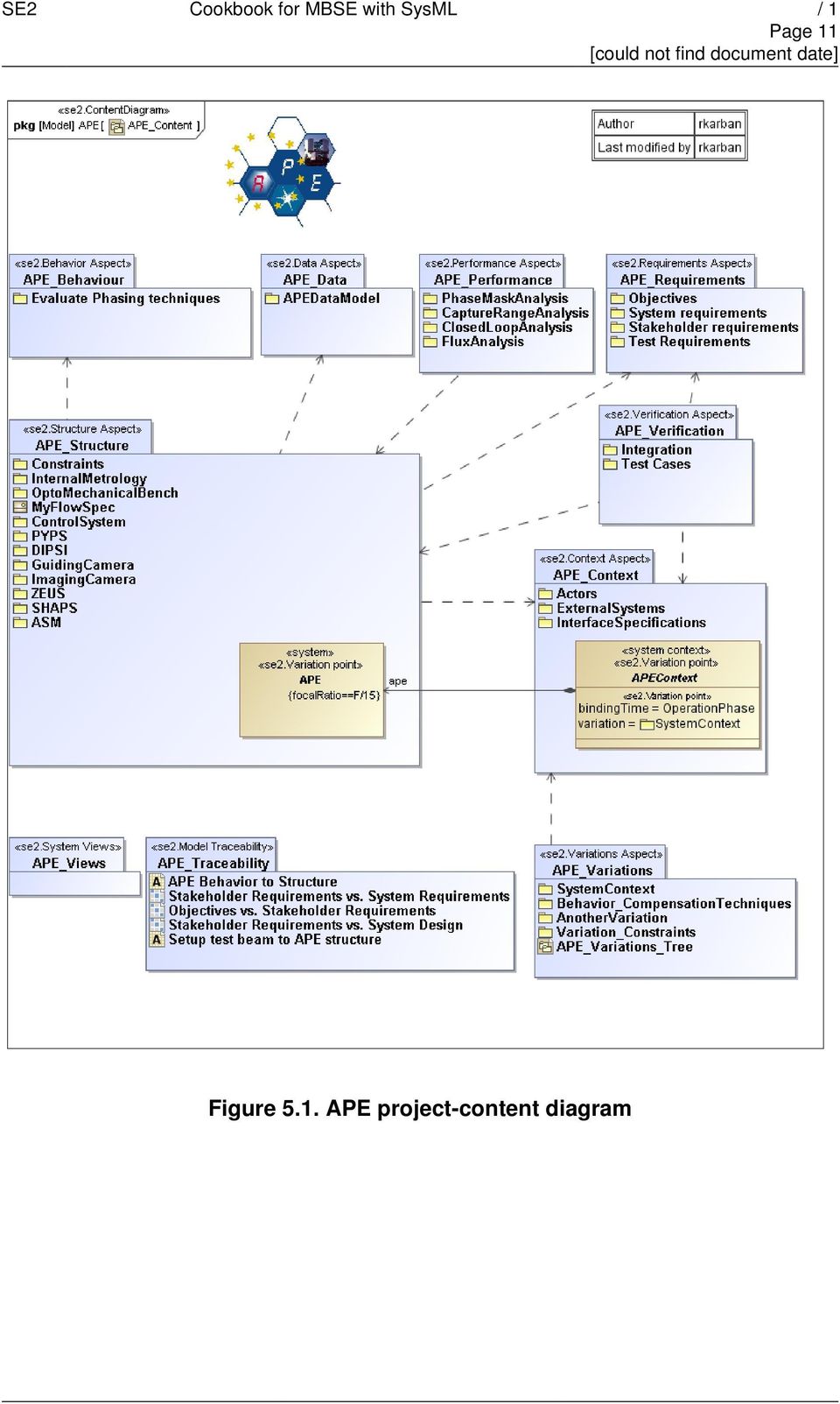
10 Page 10 Chapter 5. APE Model Structure Pattern 5.1. Introduction 5.2. Overview Diagrams To further improve the understandability of the APE model content diagrams are provided, which describe the system by showing all the different aspects captured by the model. The top-level overview diagram is a "project content" diagram Figure 5.1, APE project-content diagram and serves as an entry point and an anchor for navigation through the complex model. The System Structure View ("APE_Structure" in Figure 5.1, APE project-content diagram ) is used to decompose the system and provide the recursive modeling pattern within the subsystem package; for example, the "APE_Structure" sub-package "InternalMetrology" contains the same view packages, the "InternalMetrology" sub-package "PhaseModulator" Figure 5.2, Subsystem content diagram contains again the same view packages, and so on. For every system decomposition element (like the nested structure view for the "InternalMetrology" in Figure 5.2, Subsystem content diagram ), a package exists together with an overview diagram that shows the aspect packages of the respective element. The arrows between the packages show their dependencies. This recursive model structure provides an intuitive look-and-feel navigation capability within the APE model.

11 Page 11 Figure 5.1. APE project-content diagram
12 Page Aspects 5.4. Objectives and Requirements Figure 5.2. Subsystem content diagram APE, like any complex system, has a large number of functional, performance, physical, and interface requirements that have to be satisfied. This implies the need for formal requirements management during the project. APE has about 50 high-level system requirements. The control system has also about 50 requirements, refined by 150 use cases. We used the SysML requirements diagrams to show the main objectives of APE (Figure 5.3, APE objectives diagram ). The limitations of standard text-based requirements-management tools were overcome by visualizing key requirements and their impact on system design and verification in an intuitive way. The following user defined types extend the SysML requirements modeling features to organize and trace objectives, business and system requirements of APE. Figure 5.4, Traceability among different types of requirements shows the dependencies of the requirements and automatically created traceability matrices. In the figure, objectives are project-specific stereotypes of a class to capture the objectives for the projects (see Figure 5.3, APE objectives diagram ); stakeholder requirements are project-specific stereotypes of a SysML requirement to capture the high-level requirements for the projects; and for the system requirements, SysML requirements are used to capture the detailed requirements for the projects.

13 Page 13 Figure 5.3. APE objectives diagram Figure 5.4. Traceability among different types of requirements

14 Page Context The system's context defines the system's boundaries and is modeled using SysML internal block diagrams. A SysML internal block diagram (IBD) shows a block, its parts, and its interfaces. For the system context our main focus is on system interfaces. SysML uses ports to model the interfaces of a block. SysML provides a standard port for service-like interfaces and flow ports for physical interfaces. However, there are different possibilities to use these ports for capturing system interfaces (see Figure 5.5, Internal block diagram of electrical context ): Standard ports to model abstract interfaces as representation of an interface control document (ICD) as shown for port "scp" Flow ports for a combination of mechanical and flow interface at block level (model physical and logical properties at the border of a block, hiding its internals), as shown for port "15-N-A" Model mechanical and flow interface directly at the specific part level, as shown for "coolantreturn" and "coolantsupply," crossing the border of the outer part Model mechanical and flow interface at block and part level, as shown for port "15-N-C" To ensure consistency between the interface control document and the model, the latter serves as the basis for the former. Figure 5.5, Internal block diagram of electrical context shows the context of the telescope from an electrical viewpoint (ports on control system side are not modeled).

15 Page 15 Figure 5.5. Internal block diagram of electrical context

16 Page System Structure The system structure is maybe the most self-evident aspect to model. We have used SysML block definition diagrams (BDDs) to model the product tree and internal block diagrams to model the structure and interfaces of APE and its subsystem. The APE hierarchical breakdown is based on the product tree. It has several levels, going from the highest level into more and more details, using decomposition of its elements. On the other hand, a complex system has much more than just one internal structure. There are multiple views showing electrical, optical, and mechanical elements that are interconnected, and therefore multiple structures exist. The same components can be connected in different views in different ways. We have used IBDs to show the electrical, optical, and mechanical layout of APE and its components at different levels. Figure 5.6, IBD of the APE optical layout shows the optical layout in an abstract manner. The connectors are stereotyped as optical, but they are elided for readability.

17 Page Behavior Figure 5.6. IBD of the APE optical layout A complex system is much more than just the collection of its elements and their structural architecture, because its behavior derives from the collaboration of its parts. Therefore it is essential to capture the

18 Page 18 behavior of the system to be able to understand it. We have used activities to model the behavior of APE and its subsystems. SysML activity diagrams can be used to show the actions taken by the system and its data and control flow. Figure 5.7, Activity diagram for APE wave-front control shows the wavefront control of APE. It shows at the same time the physical effects of the system (like distortion of the wave front), as well as sensing, actuating actions, and control flows Data Figure 5.7. Activity diagram for APE wave-front control Another aspect is the information or data handled by the system. SysML provides block definition diagrams for the definition of data, and it provides internal block diagrams, activities, and sequence diagrams for data usage and flow. APE uses SysML "datatypes" to define the data of APE and its subsystems. Figure 5.8, Block definition diagram of APE wave-front data shows the composition structure of a measurement and its relation to movements of the segmented mirror ("AsmMovement"). Those data types are used to define ports in IBDs and objects in activity diagrams.

19 Page 19 Figure 5.8. Block definition diagram of APE wave-front data

20 Page Verification For every large system, verification is an essential part of the system acceptance in order to prove that the system meets its requirements. SysML supports the modeling of test cases with a specific model element, "testcase". The "testcase" element can be used at different levels for component integration, software integration, and system integration. Furthermore, APE has two different test contexts: verification in the lab and in the sky.

21 Page 21 Chapter 6. Model Library and Systems-Engineering Profile Besides the modeling of the different aspects, the APE modeling project provides a model library and an SE^2 profile. Data types and model elements that are frequently used are modeled in a model library to increase reuse. Abstract types are used as place holder for specific building blocks. They are classified in different catalogue packages (Figure 6.1, APE abstract types ). Figure 6.1. APE abstract types Catalogues can be easily extended by using inheritance. Furthermore, the preliminary design of a system can initially work with an abstract type (when the detailed requirements are yet unknown) and decide later which specific type to use for the implementation. A generic connector gets a different context-specific pin assignment by inheritance. For each specific assignment a separate specialization is needed. The SE^2 profile provides the project-specific extensions to SysML: stereotypes like "objective", constraints in element usage, enumerations, and so on.
22 Page 22 Chapter 7. Modeling Challenges 7.1. Introduction 7.2. Notation: Connection of Nested Blocks Figure 7.1, Nested connectors shows the connection of control-system elements with telescope elements: for example, the sensor cabinet ("senscabinet") is connected with the "coolantreturn" and "coolantsupply." The solid line is a nested connector. It crosses the boundaries of the encapsulated system blocks. If the modeler would like to hide the internal structure of the telescope in Figure 7.1, Nested connectors, the nested connector would also be hidden. Typically we still want to see that there is some kind of relationship between the telescope and APE. SysML doesn't provide a presentation option to show the link in this case. As a workaround we propose a standard port with stereotype junction that divides the nested connector at each relevant boundary crossing in separate connectors. Figure 7.2, Junction ports for nested connector shows that the junction port resolves the issue (see also Figure 5.5, Internal block diagram of electrical context ). We propose that SysML support the concept of junction ports, which would enable tools to offer convenience functions for nested connector modeling (we have issued this proposal to the SysML Revision Task Force). Figure 7.1. Nested connectors
23 Page Model Figure 7.2. Junction ports for nested connector SysML supports two kinds of ports, that is, interaction points between a system block and its environment. The standard port provides or requests services, whereas the flow port specifies the flow of items inside or outside the system block. SysML has no explicit support of more complex ports that combine single, reusable ports. We propose nested ports for SysML. They allow a decomposing structure, the potential for re-usability and individual delegation of item flows that go through this port (see Figure 5.5, Internal block diagram of electrical context ). Nested ports conform to the abstract syntax of SysML. Therefore some tool vendors already provide this important modeling feature. SysML doesn't say anything about the semantics of nested ports. Because we issued this proposal to the SysML Revision Task Force, a forthcoming SysML version will include a special kind of this concept called nested flow ports Tool SysML has some modeling areas where creating and editing model information in a diagram is cumbersome. For example for requirements, which are often entered in a bulk, it is easier to use a table than a diagram to enter or modify the data. The same is true for relationship modeling like the allocation of behavioral elements to structural system elements. It is easier to assign the relationships in a matrix than in a diagram with lots of arrows. SysML already defines table and matrix formats. Most tools provide them as limited read-only views on the model. What we need are table and matrix views with the ability to create and modify model elements Methodology SysML is a pure language and does not prescribe any methodology. For example, SysML allows one to model the "allocate" relationship between nearly any model elements. But where is this feature useful in a specific project? How can the relationship be determined from the model? What are the consequences of having an "allocate" relationship between two elements? You don't find answers to these questions in
24 Page 24 the SysML specification. While there are some books that describe methodologies for modeling systems with SysML (Friedenthal 2008; Weilkiens 2008), our MBSE Challenge Team has found some best practices and modeling guidelines to complement them. Last but not least, each project needs its own specific set of methods Configuration and Quality Control As soon as a common project model is created and more than one person uses it, configuration control becomes a fundamental requirement. In particular, consistent linking among model elements must be ensured. Individual changes must be traceable as well as creating visual differences to follow in detail what has changed where. Due to the extensive linking, side effects (introduced by changes) can go unnoticed and corrupt the model. This can only be mitigated by establishing rigorous configurationmanagement practices and using tools that allow rollbacks.
25 Page 25 Chapter 8. Experiences from a New Project - E-ELT Telescope Control System The European Extremely Large Telescope is a telescope with a primary mirror of 42 m in diameter, composed of 984 hexagonal segments, and four other mirrors with diameters ranging from 2.5 m to 6 m. Figure 8.1, Size comparison of the European Extremely Large Telescope (left), the Very Large Telescope (center) and the Roman Colosseum (right). (Image created by ESO; reprinted by permission.) shows the E-ELT in comparison with the Very Large Telescope and the Roman Colosseum, which might be an indicator for its complexity. Figure 8.1. Size comparison of the European Extremely Large Telescope (left), the Very Large Telescope (center) and the Roman Colosseum (right). (Image created by ESO; reprinted by permission.) The telescope consists roughly of 10,000 tons of steel and glass in a structure the size of a big football stadium; it needs 20,000 actuators, some of which have to be controlled to location accuracies within a nanometer and to angular accuracies within 0.02 degrees. It requires high-performance computation up to 700 Gflop/s, and data transfers rates of up to 17 Gbyte/s. The control system has to deal with about 60,000 I/O points, 15 subsystems (one particular subsystem requires the coordination of 15,000 actuators alone), and interacting, distributed control loops with sampling rates ranging from 0.01 Hz to several khz. The telescope control system (TCS) includes all the hardware, software, and communication infrastructure required to control the telescope and the dome. Many subsystems will be contracted and have to be properly integrated. Therefore, the TCS defines for the subsystems the interfaces and requirements as well as standards for the field electronics, software, and hardware to be used. The common project model, where all TCS-relevant components of the observatory are logically represented, enables the development team to share a common, consistent view of the system, like the context in figure 14; structure requirements, in combination with a requirements management tool; describe the complex behavior of the system; define the architecture and detailed design; standardize meta-architecture across the various subsystems;
26 Page 26 allocate function to structure and allow full traceability; and analyze different design variants. TCS architecture is highly data-oriented, making it well suited for representation with SysML constructs like activities and pins, blocks and ports, and state machines. The design of the TCS covers different views as control, electrical, and even mechanical because components have to be mechanically mounted. Diagrams are extracted from the model to create paper-based documentation, as required by the project. The reporting and plug-in facilities of the modeling tool allow the engineer to automatically create the recursive structure as defined by the guidelines, and to make cost estimates using a predefined parts catalogue and estimates of the required communication infrastructure to accommodate the necessary throughput. Figure 8.2. TCS context diagram
27 Page 27 Figure 8.3. Meta-architecture of the local control system The successful application of MBSE to a project of this scale was only made possible by the existence of the guidelines produced by the SE^2 Challenge Team. We consider those guidelines, together with their accompanying examples, a precondition to allow one to focus on the content, rather than on handson technicalities.
28 Page 28 Chapter 9. Conclusions The SE^2 Challenge team used an existing, complex system to create a comprehensive SysML model and solve common daily modeling problems. The engineering team of the E-ELT TCS is able to successfully apply the established guidelines, model structures, and modeling procedures to a new large-scale system in the optical telescope domain. The results demonstrate that SysML is an effective tool to document the complexity of requirements, interfaces, behavior, and structure, and is instrumental to enhance the traceability between requirements, design, and verification and validation. A formal language and an adequately strict tool enforce structured thinking and a detailed description of the problem at hand. This increases the consistency and reveals undefined or unclear parts of the problem. Some limits of SysML were reached, because it does not offer out-of-the-box concepts for optical or electrical engineering. However, this can be overcome by extending the language using domain-specific profiles. The most important value in a systems-engineering project is to have a common understanding among all stakeholders; therefore, fancy SysML constructs should be avoided when starting up. Even if SysML is a very good tool for communication and improving understanding, not all aspects of systems engineering can be fully covered by modeling with SysML, and systems engineers will still need the expressiveness and level of detail of traditional engineering activities like numerical analysis, simulation and prototyping to handle non-functional aspects like safety, security, reliability, usability, and logistics.
29 Page 29 Chapter 10. References ESO (European Southern Observatory) Very large telescope information. ESO (Web site). (accessed 3 Nov. 2009). Friedenthal, S., A. Moore, and R. Steiner A practical guide to SysML: The systems modeling language. Burlington, MA: Elsevier/Morgan Kaufmann. Gonte, F. Y. J., N. Yaitskova, P. Dierickx, R. Karban, A. Courteville, A. Schumacher, N. Devaney et al APE: A breadboard to evaluate new phasing technologies for a future European Giant Optical Telescope. In Ground-based Telescopes, ed. Jacobus M. Oschmann, Jr. (vol of Proceedings of SPIE [The International Society for Optical Engineering]), Bellingham, WA: SPIE. Ogren, I On principles for model-based systems engineering. Systems Engineering 3 (1): OMG (Object Management Group) OMG Systems Modeling Language (OMG SysML): version 1.1. OMG document no. formal/ (accessed 3 Nov. 2009). Weilkiens, T Systems engineering with SysML/UML: Modeling, analysis, design. Amsterdam: Morgan Kaufmann OMG Press/Elsevier.
30 SE2 Challenge Team Part II. Recipes and best Practices
31 Page 31 Chapter 11. Tool support Templates for Model Structure A gettemplate facility is supplied to act upon a package, and will produce a number of subpackage stereotyped by the corresponding SE2 stereotypes specified in this manual. These packages cover all the aspects of system engineering specification, e.g. Requirements, Structure, Behavior, Performance, and several others. For each of these subpackages a content diagram (BDD) stereotyped by "se2.contentdiagram", is created, where the user is supposed to add further decomposition as sensible (Chapter 5, APE Model Structure Pattern ). The diagram is intended to be used as a "entry point" for the package in which it is located, with all the packages appearing in it and containing hyperlinks for ease of navigation. Most notably, the structure package is the one which is used for recursion, where a SysML block standing for the "system", and stereotyped by "se2.physical" is created and added to the product tree Diagram. The block also contains 4 different IBD, for Electrical, Mechanical,Optical and Software (stereotyped with the respective SE2 stereotypes). The user is supposed to add packages which corresponds to the various Part Properties, and reapply the "get Template for System Element" facility to those packages. An example of the its application for a "B" element can be seen in Figure 11.1, ExampleStructure. Also, for the requirements package an element of type "Requirement" is added (the Requirement ID counter is unique throughout the model) and a Requirement diagram containing it.
32 Page 32 Figure ExampleStructure
MBSE Practices in Telescope Modeling. Section I: Introduction. Project Description
 MBSE Practices in Telescope Modeling Robert Karban, rkarban@eso.org; Tim Weilkiens, tim.weilkiens@oose.de, R. Hauber, rudolf.hauber@hood-group.com and R. Diekmann, rainer.diekmann@hamburg.de Section I:
Intoduction to SysML
 Intoduction to SysML a modeling language for Systems Engineering SummIT 2013, Axelborg 22. maj 2013 Ingeniørdocent Finn Overgaard Hansen, foh@iha.dk Department of Engineering Aarhus University Ver. 22.5.2013
SysML Modelling Language explained
 Date: 7 th October 2010 Author: Guillaume FINANCE, Objet Direct Analyst & Consultant UML, the standard modelling language used in the field of software engineering, has been tailored to define a modelling
Compliance and Requirement Traceability for SysML v.1.0a
 1. Introduction: Compliance and Traceability for SysML v.1.0a This document provides a formal statement of compliance and associated requirement traceability for the SysML v. 1.0 alpha specification, which
i. Node Y Represented by a block or part. SysML::Block,
 OMG SysML Requirements Traceability (informative) This document has been published as OMG document ptc/07-03-09 so it can be referenced by Annex E of the OMG SysML specification. This document describes
SCADE System 17.0. Technical Data Sheet. System Requirements Analysis. Technical Data Sheet SCADE System 17.0 1
 SCADE System 17.0 SCADE System is the product line of the ANSYS Embedded software family of products and solutions that empowers users with a systems design environment for use on systems with high dependability
3SL. Requirements Definition and Management Using Cradle
 3SL Requirements Definition and Management Using Cradle November 2014 1 1 Introduction This white paper describes Requirements Definition and Management activities for system/product development and modification
Systems Engineering Interfaces: A Model Based Approach
 Systems Engineering Interfaces: A Model Based Approach Elyse Fosse, Christopher L. Delp Jet Propulsion Laboratory, California Institute of Technology 4800 Oak Grove Drive Pasadena, CA 91109 elyse.fosse@jpl.nasa.gov
SysML Vad och varför. Varför Vad. Diskussion. Relation till UML Innehåll Struktur Beteende Krav Cross cutting constructs. Allocations Profiles
 SysML Vad och varför Bakgrund Varför Vad Relation till UML Innehåll Struktur Beteende Krav Cross cutting constructs Diskussion Allocations Profiles Bakgrund SysML Formell standard 2007-09-01 http://www.omg.org/spec/sysml/1.0/pdf
SYSML PLUGIN. version 17.0.1. user guide
 SYSML PLUGIN version 17.0.1 user guide No Magic, Inc. 2011 All material contained herein is considered proprietary information owned by No Magic, Inc. and is not to be shared, copied, or reproduced by
How To Develop Software
 Software Engineering Prof. N.L. Sarda Computer Science & Engineering Indian Institute of Technology, Bombay Lecture-4 Overview of Phases (Part - II) We studied the problem definition phase, with which
Requirements Analysis Concepts & Principles. Instructor: Dr. Jerry Gao
 Requirements Analysis Concepts & Principles Instructor: Dr. Jerry Gao Requirements Analysis Concepts and Principles - Requirements Analysis - Communication Techniques - Initiating the Process - Facilitated
Applying 4+1 View Architecture with UML 2. White Paper
 Applying 4+1 View Architecture with UML 2 White Paper Copyright 2007 FCGSS, all rights reserved. www.fcgss.com Introduction Unified Modeling Language (UML) has been available since 1997, and UML 2 was
Chap 1. Introduction to Software Architecture
 Chap 1. Introduction to Software Architecture 1. Introduction 2. IEEE Recommended Practice for Architecture Modeling 3. Architecture Description Language: the UML 4. The Rational Unified Process (RUP)
IBM Rational Rhapsody
 IBM Rational Rhapsody IBM Rational Rhapsody Reference Workflow Guide Version 1.9 License Agreement No part of this publication may be reproduced, transmitted, stored in a retrieval system, nor translated
The SPES Methodology Modeling- and Analysis Techniques
 The SPES Methodology Modeling- and Analysis Techniques Dr. Wolfgang Böhm Technische Universität München boehmw@in.tum.de Agenda SPES_XT Project Overview Some Basic Notions The SPES Methodology SPES_XT
Manage Software Development in LabVIEW with Professional Tools
 Manage Software Development in LabVIEW with Professional Tools Introduction For many years, National Instruments LabVIEW software has been known as an easy-to-use development tool for building data acquisition
Requirements engineering
 Learning Unit 2 Requirements engineering Contents Introduction............................................... 21 2.1 Important concepts........................................ 21 2.1.1 Stakeholders and
Using UML Part One Structural Modeling Diagrams
 UML Tutorials Using UML Part One Structural Modeling Diagrams by Sparx Systems All material Sparx Systems 2007 Sparx Systems 2007 Page 1 Trademarks Object Management Group, OMG, Unified Modeling Language,
A UML Introduction Tutorial
 A UML Introduction Tutorial 1/27/08 9:55 PM A UML Introduction Tutorial In this tutorial you will learn about the fundamentals of object oriented modelling, the Unified Modelling Language and the software
Managing Variability in Software Architectures 1 Felix Bachmann*
 Managing Variability in Software Architectures Felix Bachmann* Carnegie Bosch Institute Carnegie Mellon University Pittsburgh, Pa 523, USA fb@sei.cmu.edu Len Bass Software Engineering Institute Carnegie
Questions? Assignment. Techniques for Gathering Requirements. Gathering and Analysing Requirements
 Questions? Assignment Why is proper project management important? What is goal of domain analysis? What is the difference between functional and non- functional requirements? Why is it important for requirements
6-1. Process Modeling
 6-1 Process Modeling Key Definitions Process model A formal way of representing how a business system operates Illustrates the activities that are performed and how data moves among them Data flow diagramming
8. Master Test Plan (MTP)
") 8. Master Test Plan (MTP) The purpose of the Master Test Plan (MTP) is to provide an overall test planning and test management document for multiple levels of test (either within one project or across
8. Master Test Plan (MTP) The purpose of the Master Test Plan (MTP) is to provide an overall test planning and test management document for multiple levels of test (either within one project or across
INCOSE OOSEM Working Group Charter
 PURPOSE GOAL Advance the use of the Object Oriented Systems Engineering Method (OOSEM) in support of Model Based Systems Engineering (MBSE), while providing input to the ongoing development of the Systems
CHAPTER 20 TESING WEB APPLICATIONS. Overview
 CHAPTER 20 TESING WEB APPLICATIONS Overview The chapter describes the Web testing. Web testing is a collection of activities whose purpose is to uncover errors in WebApp content, function, usability, navigability,
Functional Architectures with SysML
 Functional Architectures with SysML Jesko Lamm Senior Systems Engineer jla@bernafon.ch Tim Weilkiens Managing Director tim.weilkiens@de by Bernafon AG We believe in a world, in which people with restricted
Using Use Cases for requirements capture. Pete McBreen. 1998 McBreen.Consulting
 Using Use Cases for requirements capture Pete McBreen 1998 McBreen.Consulting petemcbreen@acm.org All rights reserved. You have permission to copy and distribute the document as long as you make no changes
A Model-Driven Visualization Tool for Use with Model- Based Systems Engineering Projects
 A Model-Driven Visualization Tool for Use with Model- Based Systems Engineering Projects Kathryn Trase NASA Glenn Research Center 21000 Brookpark Road Cleveland, OH 44135 kathryn.trase@nasa.gov Eric Fink
Software Engineering Question Bank
 Software Engineering Question Bank 1) What is Software Development Life Cycle? (SDLC) System Development Life Cycle (SDLC) is the overall process of developing information systems through a multi-step
A Business Process Services Portal
 A Business Process Services Portal IBM Research Report RZ 3782 Cédric Favre 1, Zohar Feldman 3, Beat Gfeller 1, Thomas Gschwind 1, Jana Koehler 1, Jochen M. Küster 1, Oleksandr Maistrenko 1, Alexandru
Chapter 2. Data Model. Database Systems: Design, Implementation, and Management, Sixth Edition, Rob and Coronel
 Chapter 2 Data Model Database Systems: Design, Implementation, and Management, Sixth Edition, Rob and Coronel 1 In this chapter, you will learn: Why data models are important About the basic data-modeling
Contents. Introduction and System Engineering 1. Introduction 2. Software Process and Methodology 16. System Engineering 53
 Preface xvi Part I Introduction and System Engineering 1 Chapter 1 Introduction 2 1.1 What Is Software Engineering? 2 1.2 Why Software Engineering? 3 1.3 Software Life-Cycle Activities 4 1.3.1 Software
QUALITY TOOLBOX. Understanding Processes with Hierarchical Process Mapping. Robert B. Pojasek. Why Process Mapping?
 QUALITY TOOLBOX Understanding Processes with Hierarchical Process Mapping In my work, I spend a lot of time talking to people about hierarchical process mapping. It strikes me as funny that whenever I
Algorithms, Flowcharts & Program Design. ComPro
 Algorithms, Flowcharts & Program Design ComPro Definition Algorithm: o sequence of steps to be performed in order to solve a problem by the computer. Flowchart: o graphical or symbolic representation of
KNOWLEDGE FACTORING USING NORMALIZATION THEORY
 KNOWLEDGE FACTORING USING NORMALIZATION THEORY J. VANTHIENEN M. SNOECK Katholieke Universiteit Leuven Department of Applied Economic Sciences Dekenstraat 2, 3000 Leuven (Belgium) tel. (+32) 16 28 58 09
Acknowledgement. Software Engineering. CS 3141: Team Software Project Introduction
 CS 3141: Team Software Project Introduction Ali Ebnenasir Department of Computer Science Michigan Technological University Acknowledgement Betty H.C. Cheng Software Engineering Systematic approach for
Implementing reusable software components for SNOMED CT diagram and expression concept representations
 1028 e-health For Continuity of Care C. Lovis et al. (Eds.) 2014 European Federation for Medical Informatics and IOS Press. This article is published online with Open Access by IOS Press and distributed
The role of integrated requirements management in software delivery.
 Software development White paper October 2007 The role of integrated requirements Jim Heumann, requirements evangelist, IBM Rational 2 Contents 2 Introduction 2 What is integrated requirements management?
Requirements Management John Hrastar
 Requirements Management John Hrastar NASA Project Management Conference March 30-31, 2004 University of Maryland Conference Center Introduction Three aspects of requirements management Requirements in
Appendix 2-A. Application and System Development Requirements
 Appendix 2-A. Application and System Development Requirements Introduction AHRQ has set up a Distributed Systems Engineering Lab (DSEL) to support all internal development efforts and provide a facility
Engineering Process Software Qualities Software Architectural Design
 Engineering Process We need to understand the steps that take us from an idea to a product. What do we do? In what order do we do it? How do we know when we re finished each step? Production process Typical
Requirements engineering and quality attributes
 Open Learning Universiteit Unit 2 Learning Unit 2 Requirements engineering and quality attributes Contents Introduction............................................... 21 2.1 Important concepts........................................
Software Development in the Large!
 Software Development in the Large! Peter Eeles Executive IT Architect, IBM peter.eeles@uk.ibm.com IBM Rational Software Development Conference 2007 2007 IBM Corporation Agenda IBM Rational Software Development
Implementation Workflow
 Implementation Workflow Michael Fourman Introduction Implement the design in terms of components source code, scripts, binaries, executables, etc. Flesh out the architecture Plan system integrations in
PLAY-OUT FOR HIERARCHICAL COMPONENT ARCHITECTURES
 PLAY-OUT FOR HIERARCHICAL COMPONENT ARCHITECTURES Jörg Holtmann, Matthias Meyer Automotive Software Engineering, 17. September 2013 Sheet 1 Introduction and Motivation Automotive Domain Approach to cope
Software Architecture Action Guide. Why do we care about Software Architecture?
 Software Action Guide Dana Bredemeyer Bredemeyer Consulting Tel: (812) 335-1653 Fax: (812) 335-1652 Email: dana@bredemeyer.com Web: Why do we care about Software? Because we want to be a dominant player
An Automatic Tool for Checking Consistency between Data Flow Diagrams (DFDs)
") An Automatic Tool for Checking Consistency between Data Flow Diagrams (DFDs) Rosziati Ibrahim, Siow Yen Yen Abstract System development life cycle (SDLC) is a process uses during the development of any
An Automatic Tool for Checking Consistency between Data Flow Diagrams (DFDs) Rosziati Ibrahim, Siow Yen Yen Abstract System development life cycle (SDLC) is a process uses during the development of any
Tech Note: Smart Home Modeling the Internet-of- Things with SysML Part 3 Procurement to Evaluation
 75 Fifth Street NW, Suite 312 Atlanta, GA 30308, USA voice: +1-404-592-6897 web: www.intercax.com email: info@intercax.com Dr. Dirk Zwemer, InterCAX LLC Tech Note: Smart Home Modeling the Internet-of-
Data Modeling Basics
 Information Technology Standard Commonwealth of Pennsylvania Governor's Office of Administration/Office for Information Technology STD Number: STD-INF003B STD Title: Data Modeling Basics Issued by: Deputy
Budget Planner SOFTWARE REQUIREMENT SPECIFICATION. Professor: Dr. Doan Nguyen. Team Members: Bindu Madhavi K Khambam Suganya Srinivasan
 SOFTWARE REQUIREMENT SPECIFICATION Department of Computer Science, Sacramento State University Spring 2015 Budget Planner Professor: Dr. Doan Nguyen Team Members: Bindu Madhavi K Khambam Suganya Srinivasan
VAIL-Plant Asset Integrity Management System. Software Development Process
 VAIL-Plant Asset Integrity Management System Software Development Process Document Number: VAIL/SDP/2008/008 Engineering For a Safer World P u b l i c Approved by : Ijaz Ul Karim Rao Revision: 0 Page:2-of-15
11 Tips to make the requirements definition process more effective and results more usable
 1 11 Tips to make the s definition process more effective and results more usable This article discusses what I believe are the key techniques for making s definition process repeatable from project to
Fourth generation techniques (4GT)
") Fourth generation techniques (4GT) The term fourth generation techniques (4GT) encompasses a broad array of software tools that have one thing in common. Each enables the software engineer to specify some
Fourth generation techniques (4GT) The term fourth generation techniques (4GT) encompasses a broad array of software tools that have one thing in common. Each enables the software engineer to specify some
Application of UML in Real-Time Embedded Systems
 Application of UML in Real-Time Embedded Systems Aman Kaur King s College London, London, UK Email: aman.kaur@kcl.ac.uk Rajeev Arora Mechanical Engineering Department, Invertis University, Invertis Village,
Visual Programming of Logic, Motion, and Robotics
 ADVANCED Motion Controls October 2014 Visual Programming of Logic, Motion, and Robotics Sándor Barta Overview The art of programming consists of mentally translating a workflow into a sequential programming
Modelling the Management of Systems Engineering Projects
 AEROSPACE CONCEPTS Modelling the Management of Systems Engineering Projects Daniel Spencer Shaun Wilson Aerospace Concepts Pty Ltd www.concepts.aero 28 November 2012 Model-Based Systems Engineering Symposium
How To Design An Information System
 Information system for production and mounting of plastic windows MARCEL, MELIŠ Slovak University of Technology - Faculty of Material Sciences and Technology in Trnava, Paulínska 16 street, Trnava, 917
Reusable Knowledge-based Components for Building Software. Applications: A Knowledge Modelling Approach
 Reusable Knowledge-based Components for Building Software Applications: A Knowledge Modelling Approach Martin Molina, Jose L. Sierra, Jose Cuena Department of Artificial Intelligence, Technical University
Tools for Forging the Functional Architecture
 Tools for Forging the Functional Architecture Andreas Korff 1, Jesko G. Lamm 2, Tim Weilkiens 3 1 Atego Systems GmbH, Major-Hirst-Str. 11, 38442 Wolfsburg, Germany, andreas.korff atego.com 2 Bernafon
1. Process Modeling. Process Modeling (Cont.) Content. Chapter 7 Structuring System Process Requirements
 Content. Chapter 7 Structuring System Process Requirements") Content Chapter 7 Structuring System Process Requirements Understand the logical (&physical) process modeling by using data flow diagrams (DFDs) Draw DFDs & Leveling Balance higher-level and lower-level
Content Chapter 7 Structuring System Process Requirements Understand the logical (&physical) process modeling by using data flow diagrams (DFDs) Draw DFDs & Leveling Balance higher-level and lower-level
Use Cases. Massimo Felici. Massimo Felici Use Cases c 2004 2011
 Use Cases Massimo Felici Use Cases 1 Support requirements engineering activities and the requirement process Capture what a system is supposed to do, i.e., systems functional requirements Describe sequences
Lecture 9: Requirements Modelling
 A little refresher: What are we modelling? Lecture 9: Requirements Modelling Requirements; Systems; Systems Thinking Role of Modelling in RE Why modelling is important Limitations of modelling Brief overview
A Case Study of the Systems Engineering Process in Healthcare Informatics Quality Improvement. Systems Engineering. Ali M. Hodroj
 A Case Study of the Systems Engineering Process in Healthcare Informatics Quality Improvement By Ali M. Hodroj Project Report submitted to the Faculty of the Maseeh School of Engineering and Computer Science
Industrial IT Ó Melody Composer
 Overview Industrial IT Ó Melody Composer Features and Benefits Support of concurrent engineering for Control Systems Operation on Windows NT and Windows 2000 Multiple client/server architecture Off-Line
Clarifying a vision on certification of MDA tools
 SCIENTIFIC PAPERS, UNIVERSITY OF LATVIA, 2010. Vol. 757 COMPUTER SCIENCE AND INFORMATION TECHNOLOGIES 23 29 P. Clarifying a vision on certification of MDA tools Antons Cernickins Riga Technical University,
SysML a modeling language for Systems Engineering
 SysML a modeling language for Systems Engineering IDA - Dansk Selskab for Datateknik Ingeniørhuset i København, 15. Marts 2010 Finn Overgaard Hansen foh@iha.dk Ingeniørhøjskolen i Århus SysML - a modeling
Usage of Business Process Choreography
 Usage of Business Process Choreography Akira Tanaka, Hitachi, Ltd. tanakaak@soft.hitachi.co.jp Infrastructures and Standard 1 Agenda Introduction Lifecycle! Design phase! Usage phase! Managing phase Remarks
Software development life cycle. Software Engineering - II ITNP92 - Object Oriented Software Design. Requirements. Requirements. Dr Andrea Bracciali
 Software development life cycle Software life cycle: Software Engineering - II ITNP92 - Object Oriented Software Design Dr Andrea Bracciali Module Co-ordinator 4B86 abb@cs.stir.ac.uk Spring 2014 (elicitation)
Software Engineering. System Models. Based on Software Engineering, 7 th Edition by Ian Sommerville
 Software Engineering System Models Based on Software Engineering, 7 th Edition by Ian Sommerville Objectives To explain why the context of a system should be modeled as part of the RE process To describe
Component visualization methods for large legacy software in C/C++
 Annales Mathematicae et Informaticae 44 (2015) pp. 23 33 http://ami.ektf.hu Component visualization methods for large legacy software in C/C++ Máté Cserép a, Dániel Krupp b a Eötvös Loránd University mcserep@caesar.elte.hu
Process Models and Metrics
 Process Models and Metrics PROCESS MODELS AND METRICS These models and metrics capture information about the processes being performed We can model and measure the definition of the process process performers
Enterprise Architecture Modeling PowerDesigner 16.1
 Enterprise Architecture Modeling PowerDesigner 16.1 Windows DOCUMENT ID: DC00816-01-1610-01 LAST REVISED: November 2011 Copyright 2011 by Sybase, Inc. All rights reserved. This publication pertains to
A pragmatic approach to modeling large systems
 Theodore Kahn Ian Sturken NASA Ames Research Center Moffett Field, CA NASA/Army Systems and Software Engineering Forum May 11 & 12, 2010 University of Alabama, Huntsville theodore.e.kahn@nasa.gov ian.b.sturken@nasa.gov
Towards Collaborative Requirements Engineering Tool for ERP product customization
 Towards Collaborative Requirements Engineering Tool for ERP product customization Boban Celebic, Ruth Breu, Michael Felderer, Florian Häser Institute of Computer Science, University of Innsbruck 6020 Innsbruck,
Tool Support for Software Variability Management and Product Derivation in Software Product Lines
 Tool Support for Software Variability Management and Product Derivation in Software s Hassan Gomaa 1, Michael E. Shin 2 1 Dept. of Information and Software Engineering, George Mason University, Fairfax,
In: Proceedings of RECPAD 2002-12th Portuguese Conference on Pattern Recognition June 27th- 28th, 2002 Aveiro, Portugal
 Paper Title: Generic Framework for Video Analysis Authors: Luís Filipe Tavares INESC Porto lft@inescporto.pt Luís Teixeira INESC Porto, Universidade Católica Portuguesa lmt@inescporto.pt Luís Corte-Real
Business Process Modeling with Structured Scenarios
 Business Process Modeling with Structured Scenarios Doug Rosenberg ICONIX Software Engineering, Inc. In 2008, based on our experience with a number of business process engineering projects over the last
Requirements Definition and Management Processes
 Software Engineering G22.2440-001 Session 1 Sub-Topic 1 Requirements Definition & Management Processes and Tools Dr. Jean-Claude Franchitti New York University Computer Science Department Courant Institute
What is Enterprise Architect? Enterprise Architect is a visual platform for designing and constructing software systems, for business process
 1 2 3 What is Enterprise Architect? Enterprise Architect is a visual platform for designing and constructing software systems, for business process modeling, and for more generalized modeling purposes.
Requirements Engineering for Web Applications
 Web Engineering Requirements Engineering for Web Applications Copyright 2013 Ioan Toma & Srdjan Komazec 1 What is the course structure? # Date Title 1 5 th March Web Engineering Introduction and Overview
Announcements. SE 1: Software Requirements Specification and Analysis. Review: Use Case Descriptions
 Announcements SE 1: Software Requirements Specification and Analysis Lecture 4: Basic Notations Nancy Day, Davor Svetinović http://www.student.cs.uwaterloo.ca/ cs445/winter2006 uw.cs.cs445 Send your group
A Workbench for Prototyping XML Data Exchange (extended abstract)
") A Workbench for Prototyping XML Data Exchange (extended abstract) Renzo Orsini and Augusto Celentano Università Ca Foscari di Venezia, Dipartimento di Informatica via Torino 155, 30172 Mestre (VE), Italy
A Workbench for Prototyping XML Data Exchange (extended abstract) Renzo Orsini and Augusto Celentano Università Ca Foscari di Venezia, Dipartimento di Informatica via Torino 155, 30172 Mestre (VE), Italy
Agile Business Suite: a 4GL environment for.net developers DEVELOPMENT, MAINTENANCE AND DEPLOYMENT OF LARGE, COMPLEX BACK-OFFICE APPLICATIONS
 Agile Business Suite: a 4GL environment for.net developers DEVELOPMENT, MAINTENANCE AND DEPLOYMENT OF LARGE, COMPLEX BACK-OFFICE APPLICATIONS In order to ease the burden of application lifecycle management,
Model Driven Business Architecture. Pete Rivett CTO, Adaptive pete.rivett@adaptive.com
 Model Driven Business Architecture Pete Rivett CTO, Adaptive pete.rivett@adaptive.com Copyright Adaptive Ltd. 2001 Outline What is business architecture? User needs Information needs (metamodels) Use of
Extended Enterprise Architecture Framework Essentials Guide
 Extended Enterprise Architecture Framework Essentials Guide Editorial Writer: J. Schekkerman Version 1.5 2006 Preface An enterprise architecture (EA) establishes the organization-wide roadmap to achieve
Nikolay Grozev. Supervisor: Juraj Feljan, Mälardalen University Consultant: Sylvia Ilieva, University of Sofia
 University of Sofia, Faculty of Mathematics and Informatics Mälardalen University, School of Innovation, Design and Engineering Nikolay Grozev Supervisor: Juraj Feljan, Mälardalen University Consultant:
Automated Modeling of Legacy Systems Using the UML
 Automated Modeling of Legacy Systems Using the UML by Pan-Wei Ng Software Engineering Specialist Rational Software Singapore Poor documentation is one of the major challenges of supporting legacy systems;
Lecture 8. Systems engineering L E C T U R E. SIMILAR process. Zuzana Bělinová. Faculty of Transportation Sciences, CTU in Prague
 L E C T U R E 8 SIMILAR process LECTURE 8 - OVERVIEW Theoretical foundations of many methodologies - Typical SE process SYSTEMS ENGINEERING BASIC FACTS Systems Engineering is responsible for creating a
Rapid Development of Modular Dynamic Web Sites using UML
 Rapid Development of Modular Dynamic Web Sites using UML Tim Schattkowsky 1, Marc Lohmann 2 1 Paderborn University, C-LAB, D-33102 Paderborn, Germany tim@c-lab.de 2 Paderborn University, Department of
Aerospace Software Engineering
 16.35 Aerospace Software Engineering Software Architecture The 4+1 view Patterns Prof. Kristina Lundqvist Dept. of Aero/Astro, MIT Why Care About Software Architecture? An architecture provides a vehicle
Generating Aspect Code from UML Models
 Generating Aspect Code from UML Models Iris Groher Siemens AG, CT SE 2 Otto-Hahn-Ring 6 81739 Munich, Germany Iris.Groher@fh-hagenberg.at Stefan Schulze Siemens AG, CT SE 2 Otto-Hahn-Ring 6 81739 Munich,
How To Write A Train Control System
 di Base tesi di laurea magistrale Model Driven Engineering of railway control systems with the openetcs process Anno Accademico 2013-2014 relatore Ch.mo Prof. Stefano Russo correlatori Ch.mo Dr. Domenico
Patterns in. Lecture 2 GoF Design Patterns Creational. Sharif University of Technology. Department of Computer Engineering
 Patterns in Software Engineering Lecturer: Raman Ramsin Lecture 2 GoF Design Patterns Creational 1 GoF Design Patterns Principles Emphasis on flexibility and reuse through decoupling of classes. The underlying
Designing Real-Time and Embedded Systems with the COMET/UML method
 By Hassan Gomaa, Department of Information and Software Engineering, George Mason University. Designing Real-Time and Embedded Systems with the COMET/UML method Most object-oriented analysis and design
A Methodology for the Development of New Telecommunications Services
 A Methodology for the Development of New Telecommunications Services DIONISIS X. ADAMOPOULOS Centre for Communication Systems Research School of Elec. Eng., IT and Mathematics University of Surrey Guildford
Test Automation Architectures: Planning for Test Automation
 Test Automation Architectures: Planning for Test Automation Douglas Hoffman Software Quality Methods, LLC. 24646 Heather Heights Place Saratoga, California 95070-9710 Phone 408-741-4830 Fax 408-867-4550
To introduce software process models To describe three generic process models and when they may be used
 Software Processes Objectives To introduce software process models To describe three generic process models and when they may be used To describe outline process models for requirements engineering, software
Service-oriented Development of Federated ERP Systems
 Service-oriented Development of Federated ERP Systems Nico Brehm, Jorge Marx Gómez Department of Computer Science, Carl von Ossietzky University Oldenburg, Ammerländer Heerstrasse 114-118, 26129 Oldenburg,
Modeling Guidelines Manual
 Modeling Guidelines Manual [Insert company name here] July 2014 Author: John Doe john.doe@johnydoe.com Page 1 of 22 Table of Contents 1. Introduction... 3 2. Business Process Management (BPM)... 4 2.1.