Intoduction to SysML
|
|
|
- Godfrey Adams
- 8 years ago
- Views:
Transcription
1 Intoduction to SysML a modeling language for Systems Engineering SummIT 2013, Axelborg 22. maj 2013 Ingeniørdocent Finn Overgaard Hansen, foh@iha.dk Department of Engineering Aarhus University Ver

2 Agenda Systems Engineering and SysML What is SysML? New SysML concepts and diagrams 1. SysML Requirements 2. SysML Structure 3. SysML Behaviour 4. SysML Parametric Perspectives for SysML & Summary Slide 2

3 Model Based Systems Engineering (MBSE) From a document-based to a model-based approach A model-based approach requires modeling concepts and tools MBSE: producing and controlling a coherent System Model SysML is created to realize an MBSE approach based on a System model of the wanted system SysML is a modeling language not a System Engineering (SE) process Slide 3
 process")
4 What is SysML? A graphical modeling language created in response to the UML for Systems Engineering RFP developed by OMG and INCOSE. a UML Profile that represents a subset of UML 2 with important extensions Supports the specification, analysis, design, verification and validation of systems that include hardware, software, data, personnel, procedures, and facilities Supports model and data interchange via XMI SysML is a Critical Enabler for Model Driven or Model Based Systems Engineering Slide 4

5 SysML Specification - History and Status Nov. 1997: UML V1.1 launched by OMG March 2003: The UML for Systems Engineering RFP (Request for Proposal) was developed jointly by OMG and INCOSE The SysML specification was developed in response to these requirements by the diverse group of tool vendors, end users, academia, and government representatives July 2005: UML V2.0 Sept. 2007: OMG SysML v.1.0 Nov. 2008: OMG SysML v1.1 (256 pages) June 2012: OMG SysML v.1.3 (doc.id: , 250 pages) Slide 5

6 System Model and HW/SW Components SysML UML Slide 6

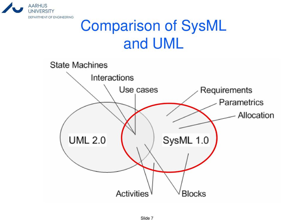
7 Comparison of SysML and UML Slide 7
8 SysML Diagram Taxonomy SysML Diagram Structure Diagram Requirement Diagram Behavior Diagram Block Definition Diagram Internal Block Diagram Package Diagram Use Case Diagram Sequence Diagram State Machine Diagram Activity Diagram Parametric Diagram New Diagram Type Modified from UML 2.x Same as UML 2.x Slide 8

9 The 4 Pillars of SysML 2: 3: 1: 4: Slide 9

10 1. SysML Requirements Requirement Diagram a NEW diagram type Graphical visualization of requirements Functional Non-functional Requirements can graphical be related to: Other requirements Design elements Test Cases Standard stereotypes: derive, satisfy, verify, refine, trace and copy Used for requirement traceability Slide 10

11 Requirements Diagram (req) - Example Slide 11

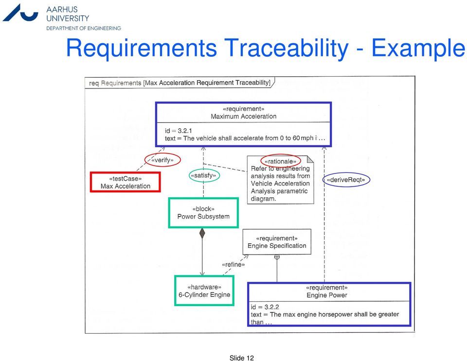
12 Requirements Traceability - Example Slide 12
13 2. SysML Structure UMLs class concept is replaced with the Block concept A Block connects to other blocks via Ports Class diagrams are replaced with Block Definition Diagrams (bdd) Each Block has an Internal Block Diagram (ibd) where the internal parts are connected via ports a replacement for class composite diagrams Ports can connect discrete as well as continuous flows of material or information Slide 13

14 Blocks are Basic Structural Elements Slide 14

15 Block Definition Diagram (bdd) - Example Slide 15
 -")
16 Internal Block Diagram (ibd) for an Automobile Domain Port Slide 16

17 Block Definition Diagram (bdd) - Example Slide 17
 -")
18 Internal Block Diagram (ibd) - Example Running the Vehicle Software Part Slide 18

19 Ibd [Block] Camera [Nested flow] Proxy Ports :Light :Camera Module :Electronic Assembly :Light :Optical Assembly :Light :MPEG Converter :Video :MPEG4 <> camera i/o: Camera Interface :Imaging Assembly :Image :Image :Image Processor Proxy port Slide 19 «flow specification» Camera Interface flowproperties out digital video: MPEG4 out analog video: Composite in control: Control Data in startup sig: Start Up

20 Standard service based Ports (Full port) Camera Control camera requests Monitoring Station Required interface Provided interface «interface» Camera Control operations getcamerastatus(in cameraid: Integer, in camerastatus: String) testcameras() pancamera(in strength: Integer) tiltcamera(in strength: Integer) Slide 20
 testcameras() pancamera(in strength: Integer) tiltcamera(in strength:")
21 3. SysML - Behavior Activity diagrams are enhanced with new concepts Flows can be continuous and model information as well as material flow Control flows are introduced SysML activities are based on token-flow semantics related to Petri-Nets Tokens corresponds to values of inputs, outputs and control Activities can have pins (acting as a buffer) Slide 21
22 Activity Diagram (act) Notation Flows can be discrete, streaming or control Slide 22
23 Activity Diagram (act) - Example swimlanes Slide 23
24 Activity Diagram - decomposed act Operate Camera [Object Flow] «optional» current image {stream} :CollectImages Activity parameter node Object flow captured image {stream} :CaptureVideo video out {stream} input signal {stream} :GenerateVideo Outputs Have subdiagrams «optional» MPEG output {stream} «optional» Composite out {stream} Slide 24
25 4. SysML Parametric Parametric Diagram (par) a NEW diagram type Used to express constraints (equations) between value properties Provides support for engineering analysis (e.g., performance, reliability) Constraint block captures equations shown on a bdd Expression language can be formal (e.g., MathML, OCL) or informal A computational engine is defined by applicable analysis tool and not by SysML Parametric diagrams represents the usage of the constraints in an analysis context Binding of constraint usage to value properties of blocks (e.g., vehicle mass bound to F= m a) Parametric enable integration of engineering analysis with design models Slide 25
26 BDD Parametric Constraint Blocks Stereotype Slide 26
27 Parametric Diagram (par) - Example for a block Value bindings Slide 27
28 Structure Cross Connecting Model Elements ibd [block] Anti-LockController satisfies [Internal Block Diagram] «requirement» Anti-Lock Performance ibd [block] Anti-LockController [Internal Block Diagram] d1:tractiondetector act PreventLockup [Swimlane Diagram] «allocate» act PreventLockup :TractionDetector [Activity Diagram] «allocate» :BrakeModulator Behavior c1:modulator c1:modulator Interface Interface c1:modulator interface allocatedfrom «ObjectNode» TractionLoss: allocatedfrom «activity»detectlos d1:traction OfTraction Detector m1:brakemodulator m1:brake allocatedfrom Modulator «activity»modulate BrakingForce values DutyCycle: Percentage DetectLossOf Traction TractionLoss: Modulate BrakingForce allocatedto «connector»c1:modulatorinterface Requirements satisfy req [package] VehicleSpecifications [Requirements Diagram - Braking Requirements] Vehicle System Braking Subsystem Specification Specification par [constraintblock] StraightLineVehicleDynamics [Parametric Diagram] v.chassis.tire. v.brake.abs.m1. v.brake.rotor. Friction: DutyCycle: BrakingForce: v.weight: par [constraintblock] StraightLineVehicleDynamics [Parametric Diagram] tf: tl: bf: m: c Parametrics «requirement» «requirement» StoppingDistance Anti-LockPerformance id= 102 id= 337" text= The vehicle shall stop text= Braking subsystem from 60 mph within 150 ft shall prevent wheel lockup on a clean dry surface. under all braking conditions. VerifiedBy SatisfiedBy «interaction»minimumstopp «block»anti-lockcontroller ingdistance «derivereqt» :BrakingForce Equation [f = (tf*bf)*(1-tl)] :DistanceEquation [v = dx/dt] x: f: v: F: v: :Accelleration Equation [F = ma] a: a: :VelocityEquation [a = dv/dt] «derivereqt» v.position: Slide 28
29 Project activities using SysML Capture and analyze black box system requirements System Context & System Use Cases, Requirement Diagrams Develop one ore more candidate system architectures Block Definition & Internal Block Diagrams Perform engineering trade-off analysis to evaluate and select the optimal architecture Parametric Diagrams Specify component requirements and their traceability to system requirements Requirement diagrams Verify the system design by executing system-level test cases Slide 29
30 Perspectives for SysML Enable a common modeling language and model across engineering disciplines Enable traceability between disciplines Enable different kinds of system analysis Enable integration of discrete and continuous based modeling tools Critical enabler for Model Based System Engineering with tool support Slide 30
31 Summary SysML a common modeling language for different disciplines e.g. Hardware, Software and Mechanics New and important concepts for cross disciplinary analysis of system properties (e.g. parametric) Blocks and ports as general modeling elements Important enhancement to activity diagrams Lot of support for traceability between models and model elements Must be supported by an appropriate Systems Engineering (SE) process Slide 31
32 References OMGs SysML homepage: INCOSE organization: Books: A Practical Guide to SysML The System Modeling Language, Sanford Friedenthal, Allan Moore, Rick Steiner, Elsevier, Systems Engineering with SysML/UML Modeling, Analysis, Design, Tim Weilkiens, Elsevier, Slide 32
SysML a modeling language for Systems Engineering
 SysML a modeling language for Systems Engineering IDA - Dansk Selskab for Datateknik Ingeniørhuset i København, 15. Marts 2010 Finn Overgaard Hansen foh@iha.dk Ingeniørhøjskolen i Århus SysML - a modeling
i. Node Y Represented by a block or part. SysML::Block,
 OMG SysML Requirements Traceability (informative) This document has been published as OMG document ptc/07-03-09 so it can be referenced by Annex E of the OMG SysML specification. This document describes
SysML Modelling Language explained
 Date: 7 th October 2010 Author: Guillaume FINANCE, Objet Direct Analyst & Consultant UML, the standard modelling language used in the field of software engineering, has been tailored to define a modelling
MBSE Practices in Telescope Modeling. Section I: Introduction. Project Description
 MBSE Practices in Telescope Modeling Robert Karban, rkarban@eso.org; Tim Weilkiens, tim.weilkiens@oose.de, R. Hauber, rudolf.hauber@hood-group.com and R. Diekmann, rainer.diekmann@hamburg.de Section I:
What is Modeling language? What is UML? A brief history of UML Understanding the basics of UML UML diagrams for NES UML Profiles UML Modeling tools
 What is Modeling language? What is UML? A brief history of UML Understanding the basics of UML UML diagrams for NES UML Profiles UML Modeling tools 1 A modeling language is any artificial language that
Compliance and Requirement Traceability for SysML v.1.0a
 1. Introduction: Compliance and Traceability for SysML v.1.0a This document provides a formal statement of compliance and associated requirement traceability for the SysML v. 1.0 alpha specification, which
Automotive System and Software Architecture
 Automotive System and Software Architecture Yanja Dajsuren 2IW80 Software specification and architecture March 25, 2014 Which one has more software? Chevrolet Volt, an example modern day car Boeing 787,
System Analysis using SysML Parametrics: Current Tools and Best Practices
 Model-Based Systems Engineering Center System Analysis using SysML Parametrics: Current Tools and Best Practices Chris Paredis Model-Based Systems Engineering Center Georgia Tech Chris.paredis@me.gatech.edu
SysML Vad och varför. Varför Vad. Diskussion. Relation till UML Innehåll Struktur Beteende Krav Cross cutting constructs. Allocations Profiles
 SysML Vad och varför Bakgrund Varför Vad Relation till UML Innehåll Struktur Beteende Krav Cross cutting constructs Diskussion Allocations Profiles Bakgrund SysML Formell standard 2007-09-01 http://www.omg.org/spec/sysml/1.0/pdf
INCOSE OOSEM Working Group Charter
 PURPOSE GOAL Advance the use of the Object Oriented Systems Engineering Method (OOSEM) in support of Model Based Systems Engineering (MBSE), while providing input to the ongoing development of the Systems
SYSML PLUGIN. version 17.0.1. user guide
 SYSML PLUGIN version 17.0.1 user guide No Magic, Inc. 2011 All material contained herein is considered proprietary information owned by No Magic, Inc. and is not to be shared, copied, or reproduced by
Functional Architectures with SysML
 Functional Architectures with SysML Jesko Lamm Senior Systems Engineer jla@bernafon.ch Tim Weilkiens Managing Director tim.weilkiens@de by Bernafon AG We believe in a world, in which people with restricted
SCADE System 17.0. Technical Data Sheet. System Requirements Analysis. Technical Data Sheet SCADE System 17.0 1
 SCADE System 17.0 SCADE System is the product line of the ANSYS Embedded software family of products and solutions that empowers users with a systems design environment for use on systems with high dependability
OMG Systems Modeling Language (OMG SysML ) Tutorial. September, 2009
 Tutorial. September, 2009") OMG Systems Modeling Language (OMG SysML ) Tutorial September, 2009 Copyright 2006-2009 by Object Management Group. Published and used by INCOSE and affiliated societies with permission. Sanford Friedenthal
OMG Systems Modeling Language (OMG SysML ) Tutorial September, 2009 Copyright 2006-2009 by Object Management Group. Published and used by INCOSE and affiliated societies with permission. Sanford Friedenthal
3SL. Requirements Definition and Management Using Cradle
 3SL Requirements Definition and Management Using Cradle November 2014 1 1 Introduction This white paper describes Requirements Definition and Management activities for system/product development and modification
USING SYSML IN THE PRODUCT DEVELOPMENT PROCESS OF MECHATRONIC SYSTEMS
 INTERNATIONAL DESIGN CONFERENCE - DESIGN 200 Dubrovnik - Croatia, May 7-20, 200. USING SYSML IN THE PRODUCT DEVELOPMENT PROCESS OF MECHATRONIC SYSTEMS M. Follmer, P. Hehenberger, S. Punz and K. Zeman Keywords:
Building Bridges Between Systems and Software with SysML and UML
 Building Bridges Between Systems and Software with SysML and UML Matthew Hause Francis Thom ARTiSAN Software Tools ARTiSAN Software Tools Eagle Tower, Suite 70 Eagle Tower, Suite 70 Cheltenham, Gloucestershire,
UML Activities & Actions. Charles ANDRE - UNSA
 UML Activities & Actions Action & Object Nodes Accept inputs, start behaviors, provide outputs Object/Data flow Control flow Send Envoice Invoice Make Payment Accept Payment Invoice1234: Invoice Invoice1234:
2. Requirements Capture and Analysis with UML
 2. Requirements Capture and Analysis with UML The Unified Modeling Language (version 2.2) Use case diagrams (sta
SE2 Challenge Team SE2. Cookbook for MBSE with SysML ISSUE 1. Name Date Signature
 SE2 Challenge Team SE2 Cookbook for MBSE with SysML ISSUE 1 Name Date Signature Page 2 Page 3 Authors Name Affiliation Change Record Issue Date Section / Paragraph affected Reason / Initiation Documents
Questions? Assignment. Techniques for Gathering Requirements. Gathering and Analysing Requirements
 Questions? Assignment Why is proper project management important? What is goal of domain analysis? What is the difference between functional and non- functional requirements? Why is it important for requirements
PLAY-OUT FOR HIERARCHICAL COMPONENT ARCHITECTURES
 PLAY-OUT FOR HIERARCHICAL COMPONENT ARCHITECTURES Jörg Holtmann, Matthias Meyer Automotive Software Engineering, 17. September 2013 Sheet 1 Introduction and Motivation Automotive Domain Approach to cope
The Future of Modeling in Material Handling Systems. Leon F. McGinnis Keck Virtual Factory Lab Georgia Tech. June 16, 2010
 The Future of Modeling in Material Handling Systems Leon F. McGinnis Keck Virtual Factory Lab Georgia Tech June 16, 2010 Abstract Today, when we talk about modeling in the context of material handling
Solution for Systems and Software Engineering
 IBM Software Group Foreword The file "Deskbook Rel3.pdf" is the latest version of the Rational Harmony for Systems Engineering Deskbook Release 3. ( Deskbook ), released May 28, 200. February 20 The Deskbook
UML TUTORIALS THE USE CASE MODEL
 UML TUTORIALS THE USE CASE MODEL www.sparxsystems.com.au Sparx Systems 2004 Page 1/5 describes the proposed functionality of the new system. A Use Case represents a discrete unit of interaction between
Requirements Exchange: From Specification Documents to Models
 Requirements Exchange: From Specification Documents to Models Morayo ADEDJOUMA, Hubert DUBOIS, François TERRIER Ansgar RADERMACHER UML&AADL 2011-27 April 2011, Las Vegas Agenda Big picture Challenge Technologies
Lecture 8. Systems engineering L E C T U R E. SIMILAR process. Zuzana Bělinová. Faculty of Transportation Sciences, CTU in Prague
 L E C T U R E 8 SIMILAR process LECTURE 8 - OVERVIEW Theoretical foundations of many methodologies - Typical SE process SYSTEMS ENGINEERING BASIC FACTS Systems Engineering is responsible for creating a
Astah SysML Quick Start Manual for Version 1.0
 Astah SysML Quick Start Manual for Version 1.0 Copyright 2013 Change Vision, Inc. All rights reserved. Ver1.0 Astah SysML is supported by the Measures to support global technical collaboration grant program.
How To Write A Train Control System
 di Base tesi di laurea magistrale Model Driven Engineering of railway control systems with the openetcs process Anno Accademico 2013-2014 relatore Ch.mo Prof. Stefano Russo correlatori Ch.mo Dr. Domenico
Rational Unified Process for Systems Engineering RUP SE1.1. A Rational Software White Paper TP 165A, 5/02
 Rational Unified Process for Systems Engineering RUP SE1.1 A Rational Software White Paper TP 165A, 5/02 Table of Contents INTRODUCTION...1 BUSINESS MODELING...3 SYSTEM ARCHITECTURE...4 SYSTEM ARCHITECTURE
Research Article Model Based Control System Design Using SysML, Simulink, and Computer Algebra System
 Journal of Control Science and Engineering Volume 2013, Article ID 485380, 14 pages http://dx.doi.org/10.1155/2013/485380 Research Article Model Based Control System Design Using SysML, Simulink, and Computer
The SPES Methodology Modeling- and Analysis Techniques
 The SPES Methodology Modeling- and Analysis Techniques Dr. Wolfgang Böhm Technische Universität München boehmw@in.tum.de Agenda SPES_XT Project Overview Some Basic Notions The SPES Methodology SPES_XT
Modeling Radio-Frequency Front-Ends Using SysML: A Case Study of a UMTS Transceiver
 Modeling Radio-Frequency Front-Ends Using SysML: A Case Study of a UMTS Transceiver Sabeur Lafi, Roger Champagne, Ammar B. Kouki, and Jean Belzile École de technologie supérieure, 1100 rue Notre-Dame Ouest,
Applying 4+1 View Architecture with UML 2. White Paper
 Applying 4+1 View Architecture with UML 2 White Paper Copyright 2007 FCGSS, all rights reserved. www.fcgss.com Introduction Unified Modeling Language (UML) has been available since 1997, and UML 2 was
A pragmatic approach to modeling large systems
 Theodore Kahn Ian Sturken NASA Ames Research Center Moffett Field, CA NASA/Army Systems and Software Engineering Forum May 11 & 12, 2010 University of Alabama, Huntsville theodore.e.kahn@nasa.gov ian.b.sturken@nasa.gov
Created by: Austin Davis Neel Iyer Darcie Jones Sascha Schwarz
 EMGT 587 Systems Engineering Created by: Austin Davis Neel Iyer Darcie Jones Sascha Schwarz Table of Contents Introduction... 3 Operational Scenarios... 4 1. User sets and cancels cruise control:... 4
OMG EDA Standards Review
 OMG EDA Standards Review Presented by Robert D Covington CTO & Co-Founder, Rhysome rcovington@rhysome.com 317-443-5679 1 EDA/CEP is Hard Enough without Standards What you need is a Complex Event Processing
Modelling the Railway Control Domain rigorously with a UML 2.0 Profile
 Modelling the Railway Control Domain rigorously with a UML 2.0 Profile Kirsten Berkenkötter Ulrich Hannemann Germany kirsten,ulrichh@informatik.uni-bremen.de Outline Outline 1. Context 2. Railway Control
Scenario-based Requirements Engineering and User-Interface Design
 Scenario-based Requirements Engineering and User-Interface Institut für Computertechnik ICT Institute of Computer Technology Hermann Kaindl Vienna University of Technology, ICT Austria kaindl@ict.tuwien.ac.at
Chap 1. Introduction to Software Architecture
 Chap 1. Introduction to Software Architecture 1. Introduction 2. IEEE Recommended Practice for Architecture Modeling 3. Architecture Description Language: the UML 4. The Rational Unified Process (RUP)
Mastering increasing product complexity with Collaborative Systems Engineering and PLM
 Mastering increasing product complexity with Collaborative Systems Engineering and PLM Thierry Ambroisine Dassault Systèmes 10 rue Marcel Dassault, 78140 Vélizy Villacoublay, France thierry.ambroisine@3ds.com
Systems Engineering Interfaces: A Model Based Approach
 Systems Engineering Interfaces: A Model Based Approach Elyse Fosse, Christopher L. Delp Jet Propulsion Laboratory, California Institute of Technology 4800 Oak Grove Drive Pasadena, CA 91109 elyse.fosse@jpl.nasa.gov
Integrating Legacy Code / Models with Model Based Development Using Rhapsody
 Integrating Legacy Code / Models with Model Based Development Using Rhapsody M.W.Richardson 28/11/06 1 Telelogic AB Model Driven Development Very few Green Field projects are started, nearly always there
Modelling the Management of Systems Engineering Projects
 AEROSPACE CONCEPTS Modelling the Management of Systems Engineering Projects Daniel Spencer Shaun Wilson Aerospace Concepts Pty Ltd www.concepts.aero 28 November 2012 Model-Based Systems Engineering Symposium
Tools for Forging the Functional Architecture
 Tools for Forging the Functional Architecture Andreas Korff 1, Jesko G. Lamm 2, Tim Weilkiens 3 1 Atego Systems GmbH, Major-Hirst-Str. 11, 38442 Wolfsburg, Germany, andreas.korff atego.com 2 Bernafon
Requirements engineering
 Learning Unit 2 Requirements engineering Contents Introduction............................................... 21 2.1 Important concepts........................................ 21 2.1.1 Stakeholders and
SAVI Behavior Model Integration Virtual Integration Process
 SAVI Behavior Model Integration Virtual Integration Process David Redman, AVSI Texas A&M University Copyright 2014 Boeing. All rights reserved. GPDIS_2015.ppt 1 Outline AVSI SAVI Motivation SAVI Program
Model Based Document and Report Generation for Systems Engineering
 Model Based Document and Report Generation for Systems Engineering Christopher Delp, Doris Lam, Elyse Fosse, Cin-Young Lee Jet Propulsion Laboratory, California Institute of Technology 4800 Oak Grove Drive
Dr. Jana Koehler IBM Zurich Research Laboratory
 Precise Modeling of Business Processes with the Business Process Modeling Notation BPMN 2.0 Dr. Jana Koehler IBM Zurich Research Laboratory ZRL BIT at a Glance Computer Science at ZRL: Security/Cryptography
Rotorcraft Health Management System (RHMS)
") AIAC-11 Eleventh Australian International Aerospace Congress Rotorcraft Health Management System (RHMS) Robab Safa-Bakhsh 1, Dmitry Cherkassky 2 1 The Boeing Company, Phantom Works Philadelphia Center
AIAC-11 Eleventh Australian International Aerospace Congress Rotorcraft Health Management System (RHMS) Robab Safa-Bakhsh 1, Dmitry Cherkassky 2 1 The Boeing Company, Phantom Works Philadelphia Center
Applying Use Cases to Microcontroller Code Development. Chris Gilbert Cypress Semiconductor
 Applying Use Cases to Microcontroller Code Development Chris Gilbert Cypress Semiconductor Agenda Why Use Cases Microcontroller Project Development Use Cases Defined Use Cases Composition General Example
UML TUTORIALS THE COMPONENT MODEL
 UML TUTORIALS THE COMPONENT MODEL www.sparxsystems.com.au Sparx Systems 2004 Page 1/5 The component model illustrates the software components that will be used to build the system. These may be built up
An Approach to Software Architecture Description Using UML
 An Approach to Software Architecture Description Using UML Henrik Bærbak Christensen, Aino Corry, and Klaus Marius Hansen Department of Computer Science, University of Aarhus Aabogade 34, 8200 Århus N,
Agile Model-Based Systems Engineering (ambse)
") Agile Model-Based Systems Engineering (ambse) Bruce Powel Douglass, Ph.D. Chief Evangelist, Global Technology Ambassador IBM Rational Bruce.Douglass@us.ibm.com Twitter: @BruceDouglass Yahoo: tech.groups.yahoo.com/group/rt-uml/
Agile Model-Based Systems Engineering (ambse) Bruce Powel Douglass, Ph.D. Chief Evangelist, Global Technology Ambassador IBM Rational Bruce.Douglass@us.ibm.com Twitter: @BruceDouglass Yahoo: tech.groups.yahoo.com/group/rt-uml/
Writing Use Case Scenarios for Model Driven Development
 Writing Use Case Scenarios for Model Driven Development This guide outlines how to use Enterprise Architect to rapidly build Use Cases and increase your productivity through Model Driven Development. Use
Designing Real-Time and Embedded Systems with the COMET/UML method
 By Hassan Gomaa, Department of Information and Software Engineering, George Mason University. Designing Real-Time and Embedded Systems with the COMET/UML method Most object-oriented analysis and design
Java (12 Weeks) Introduction to Java Programming Language
 Introduction to Java Programming Language") Java (12 Weeks) Topic Lecture No. Introduction to Java Programming Language 1 An Introduction to Java o Java as a Programming Platform, The Java "White Paper" Buzzwords, Java and the Internet, A Short
Java (12 Weeks) Topic Lecture No. Introduction to Java Programming Language 1 An Introduction to Java o Java as a Programming Platform, The Java "White Paper" Buzzwords, Java and the Internet, A Short
How To Create A Complex Diagram On A Computer Game
 ENTERPRISE ARCHITECT IMPORT user guide No Magic, Inc. 2013 All material contained herein is considered proprietary information owned by No Magic, Inc. and is not to be shared, copied, or reproduced by
A Comprehensive Safety Engineering Approach for Software Intensive Systems based on STPA
 www.uni-stuttgart.de A Comprehensive Safety Engineering Approach for Software Intensive Systems based on STPA STPA-based Approach STPA Safety Analysis Asim Abdulkhaleq, Ph.D Candidate Institute of Software
How To Design An Information System
 Information system for production and mounting of plastic windows MARCEL, MELIŠ Slovak University of Technology - Faculty of Material Sciences and Technology in Trnava, Paulínska 16 street, Trnava, 917
Software Development in the Large!
 Software Development in the Large! Peter Eeles Executive IT Architect, IBM peter.eeles@uk.ibm.com IBM Rational Software Development Conference 2007 2007 IBM Corporation Agenda IBM Rational Software Development
25 november 2008. SAAB Training Systems SESAM - Nov 2008, Göran Calås
 1 Projekthantering vid MDE Konfigurations och projekt/linjestyrning med Model-Driven Engineering Göran Calås Project Manager Systems Architect Nov 20, 2008 goran.calas@saabgroup.com +46 768 967167 2 Göran
Propagation of Incremental Changes to Performance Model due to SOA Design Pattern Application
 Propagation of Incremental Changes to Performance Model due to SOA Design Pattern Application Nariman Mani, Dorina C. Petriu, Murray Woodside Carleton University Department of Systems and Computer Engineering
Architecture Design & Sequence Diagram. Week 7
 Architecture Design & Sequence Diagram Week 7 Announcement Reminder Midterm I: 1:00 1:50 pm Wednesday 23 rd March Ch. 1, 2, 3 and 26.5 Hour 1, 6, 7 and 19 (pp.331 335) Multiple choice Agenda (Lecture)
Announcements. SE 1: Software Requirements Specification and Analysis. Review: Use Case Descriptions
 Announcements SE 1: Software Requirements Specification and Analysis Lecture 4: Basic Notations Nancy Day, Davor Svetinović http://www.student.cs.uwaterloo.ca/ cs445/winter2006 uw.cs.cs445 Send your group
Information Management Metamodel
 ISO/IEC JTC1/SC32/WG2 N1527 Information Management Metamodel Pete Rivett, CTO Adaptive OMG Architecture Board pete.rivett@adaptive.com 2011-05-11 1 The Information Management Conundrum We all have Data
DIPLODOCUS: An Environment for. the Hardware/Software Partitioning of. Institut Mines-Telecom. Complex Embedded Systems
 DIPLODOCUS: An Environment for Institut Mines-Telecom the Hardware/Software Partitioning of Complex Embedded Systems Ludovic Apvrille, ludovic.apvrille@telecom-paristech.fr ETR 2013, Toulouse, France Goals
Decomposition into Parts. Software Engineering, Lecture 4. Data and Function Cohesion. Allocation of Functions and Data. Component Interfaces
 Software Engineering, Lecture 4 Decomposition into suitable parts Cross cutting concerns Design patterns I will also give an example scenario that you are supposed to analyse and make synthesis from The
How To Develop Software
 Software Engineering Prof. N.L. Sarda Computer Science & Engineering Indian Institute of Technology, Bombay Lecture-4 Overview of Phases (Part - II) We studied the problem definition phase, with which
Using UML Part One Structural Modeling Diagrams
 UML Tutorials Using UML Part One Structural Modeling Diagrams by Sparx Systems All material Sparx Systems 2007 Sparx Systems 2007 Page 1 Trademarks Object Management Group, OMG, Unified Modeling Language,
Functional Architectures in SysML
 Functional Architectures in SysML Jesko G. Lamm 1, Tim Weilkiens 2 1 Bernafon AG, Morgenstrasse 131, 3018 Bern, Switzerland jla bernafon.ch 2 oose Innovative Informatik GmbH, Straßenbahnring 7,
Business Modeling with UML
 Business Modeling with UML Hans-Erik Eriksson and Magnus Penker, Open Training Hans-Erik In order to keep up and be competitive, all companies Ericsson is and enterprises must assess the quality of their
Model Driven Interoperability through Semantic Annotations using SoaML and ODM
 Model Driven Interoperability through Semantic Annotations using SoaML and ODM JiuCheng Xu*, ZhaoYang Bai*, Arne J.Berre*, Odd Christer Brovig** *SINTEF, Pb. 124 Blindern, NO-0314 Oslo, Norway (e-mail:
System Engineering Data Repository
 System Data Repository 09:00 data in the MBSE life-cycle 09:20 EGS-CC in the system context 09:40 Conceptual Modelling and ECSS 10:00 ecascade 10:20 A snapshot of systems engineering data management in
System Behaviour Analysis with UML and Ptolemy. Scope and goals
 Information included in this document are group's own property. These ones shall not be disclosed without the prior wirtten consent of Optronique. System Behaviour Analysis with UML and Ptolemy 4 th Biennal
INTERNAL SERVICES GROUP PMO
 Ownership & Awareness Program 1 Program 3 Program 4 Program 5 Program 6 Program 7 Program 2 Cap ability Development Infra structure Program n INTERNAL SERVICES GROUP ESSENTIAL FUNCTIONS Act as an interface
Model Based Management of Configurations of a Complex Systems: Common Submarine Combat System
 Model Based Management of Configurations of a Complex Systems: Common Submarine Combat System Case Study Saulius Pavalkis System Analyst Saulius.Pavalkis@nomagic.com Contents Introduction... 3 Challenges
Usage of Business Process Choreography
 Usage of Business Process Choreography Akira Tanaka, Hitachi, Ltd. tanakaak@soft.hitachi.co.jp Infrastructures and Standard 1 Agenda Introduction Lifecycle! Design phase! Usage phase! Managing phase Remarks
Acknowledgement. Software Engineering. CS 3141: Team Software Project Introduction
 CS 3141: Team Software Project Introduction Ali Ebnenasir Department of Computer Science Michigan Technological University Acknowledgement Betty H.C. Cheng Software Engineering Systematic approach for
2. Analysis, Design and Implementation
 2. Subject/Topic/Focus: Software Production Process Summary: Software Crisis Software as a Product: From Individual Programs to Complete Application Systems Software Development: Goals, Tasks, Actors,
Semantic Model Integration for System Specification
 Semantic Model Integration for System Specification Creating a Common Context for Different Model Types Dr. Oskar von Dungern enso managers gmbh Charlottenstrasse 68 10117 Berlin od@enso-managers.com Abstract:
Definition of a Software Component and Its Elements
 I' Chapter 1 Definition of a Software Component and Its Elements Bill Councill George T. Heineman 1.1 Introduction The goal of this chapter is to rigorously define terms that describe the best practices
PDES Requirements / Traceability Project
 PDES / Traceability Project Alejandro Ventura Systems Engineer Honeywell Aerospace GPDIS_2014.ppt 1 / Traceability Overview Limited project to investigate standards-based exchanges of requirements and
METHOD & TOOLS TO SECURE AND SUPPORT COLLABORATIVE ARCHITECTING OF CONSTRAINED SYSTEMS
 METHOD & TOOLS TO SECURE AND SUPPORT COLLABORATIVE ARCHITECTING OF CONSTRAINED Jean-Luc Voirin Thales Aerospace Keywords: architecture modelling method early validation Abstract ARCADIA is a system & software
How To Test Automatically
 Automated Model-Based Testing of Embedded Real-Time Systems Jan Peleska jp@tzi.de University of Bremen Bieleschweig Workshop 7 2006-05-05 Outline Technologie-Zentrum Informatik Objectives Basic concepts
Intel CoFluent Methodology for SysML *
 Intel CoFluent Methodology for SysML * UML* SysML* MARTE* Flow for Intel CoFluent Studio An Intel CoFluent Design White Paper By Thomas Robert and Vincent Perrier www.cofluent.intel.com Acronyms and abbreviations
Clarifying a vision on certification of MDA tools
 SCIENTIFIC PAPERS, UNIVERSITY OF LATVIA, 2010. Vol. 757 COMPUTER SCIENCE AND INFORMATION TECHNOLOGIES 23 29 P. Clarifying a vision on certification of MDA tools Antons Cernickins Riga Technical University,
A SoC design flow based on UML 2.0 and SystemC
 A SoC design flow based on UML 2.0 and SystemC Sara Bocchio 1, Elvinia Riccobene 2, Alberto Rosti 1, and Patrizia Scandurra 3 1 STMicroelectronics, AST Agrate Lab R&I, Italy {sara.bocchio, alberto.rosti}@st.com
Echtzeittesten mit MathWorks leicht gemacht Simulink Real-Time Tobias Kuschmider Applikationsingenieur
 Echtzeittesten mit MathWorks leicht gemacht Simulink Real-Time Tobias Kuschmider Applikationsingenieur 2015 The MathWorks, Inc. 1 Model-Based Design Continuous Verification and Validation Requirements
A HW/SW Codesign Methodology based on UML
 A HW/SW Codesign Methodology based on UML How to apply a model based UML design for an embedded system By Senior Consultant Kim Bjerge (kim.bjerge@teknologisk.dk) Copyright 2008 Danish Technological Institute
Interactive system specification. Interactive system definition. Issues to be taken into account for interactive systems
 Interactive system specification From Requirements Engineering Processes and Techniques by G. Kotonya and I. Sommerville 1998 Slide 1 Interactive system definition Interactive systems can be defined as
A Model-Based Development Process for Embedded System
 A Model-Based Development Process for Embedded System Maritta Heisel and Denis Hatebur Abstract: We present a development process for embedded systems which emerged from industrial practice. This process
jbpm Explained with Simple Use Cases
 jbpm Explained with Simple Use Cases Tom Baeyens Founder and lead of jbpm, JBoss Sept 2nd 2009 1 Agenda Business Process Management jbpm Introduction Developer Value Business Value Train ticket system
Architecture. Reda Bendraou reda.bendraou{{@}}lip6.fr http://pagesperso-systeme.lip6.fr/reda.bendraou/
 Architecture Reda Bendraou reda.bendraou{{@}}lip6.fr http://pagesperso-systeme.lip6.fr/reda.bendraou/ Some slides were adapted from L. Osterweil, B. Meyer, and P. Müller material Reda Bendraou LI386-S1
Software Development in the Fields of Embedded Systems, Safety, and Security
 Software in the Fields of Embedded Systems, Safety, and Security, Erlangen, May 2007 Maritta Heisel Joint work with Denis Hatebur and Holger Schmidt University Duisburg-Essen, Faculty of Engineering, Department
Algorithms, Flowcharts & Program Design. ComPro
 Algorithms, Flowcharts & Program Design ComPro Definition Algorithm: o sequence of steps to be performed in order to solve a problem by the computer. Flowchart: o graphical or symbolic representation of
VAIL-Plant Asset Integrity Management System. Software Development Process
 VAIL-Plant Asset Integrity Management System Software Development Process Document Number: VAIL/SDP/2008/008 Engineering For a Safer World P u b l i c Approved by : Ijaz Ul Karim Rao Revision: 0 Page:2-of-15
A UML Tool for Urbanism and Control Architecture Design Applied to 3GPP Based Architectures
 ITC19/ Performance Challenges for Efficient Next Generation Networks LIANG X.J. and XIN Z.H.(Editors) V.B. IVERSEN and KUO G.S.(Editors) Beijing University of Posts and Telecommunications Press 1987-1996
Developing SOA solutions using IBM SOA Foundation
 Developing SOA solutions using IBM SOA Foundation Course materials may not be reproduced in whole or in part without the prior written permission of IBM. 4.0.3 4.0.3 Unit objectives After completing this
Use Cases. Massimo Felici. Massimo Felici Use Cases c 2004 2011
 Use Cases Massimo Felici Use Cases 1 Support requirements engineering activities and the requirement process Capture what a system is supposed to do, i.e., systems functional requirements Describe sequences