Implementing the X-Lock-3 on the Heathkit HW-101
|
|
|
- Harvey Garrison
- 9 years ago
- Views:
Transcription
1 Implementing the X-Lock-3 on the Heathkit HW-101 Pete Juliano, N6QW I had previously installed the X-Lock-2 in a Ten Tec Corsair I and a TR-7. Subsequently I installed an X-Lock-3 in a second TR-7. I guess you can say I am hooked! Recently I got the urge to try updating and remodeling a Heathkit HW-101 SSB/CW Transceiver. That effort entailed replacing many components and making some of the welldocumented improvements. To add a modern touch I installed a digital dial from Almost All Digital Electronics (AADE). Now with the digital dial not only do I know that the radio drifts but can tell precisely how much. That led me to install the X-Lock-3 in the HW-101. This paper documents what and how it was implemented in the HW-101. Did I mention that it was a successful install? Just as I spent a great deal of time thinking how to install the digital dial the same applies to the X-Lock-3. The install in the Corsair I and both TR-7 s was relatively easy as I simply tapped into the RIT lines and that was it. The HW-101 uses a VFO as opposed to a PTO as used in the Ten Tec and Drake radios. That meant that the VFO had to be accessed not a hard task but one requiring some planning and thought. This project has five distinct tasks/phases: 1. Building the X-Lock-3 2. Modifying the VFO to accept the X-Lock-3 correction voltage 3. Installing the X-Lock-3 in the HW Building the X-Lock-3 Power Supply 5. Final Integration Ron Taylor, G4GXO, has done a superb job in developing the X-Lock kits. The documentation is well organized and provides a step by step instruction of what to do to successfully build the kit. Since this was my third kit, the elapsed time was about an hour to build the X-Lock-3. The first build took much longer and there is much to be said for the learning curve. Once built check your wiring and for the obvious solder bridges and the wrong components in the right place. Ron has taken care to sequence and identify which parts go where and at what time. Follow the instructions! In modifying the VFO it has to be removed from the radio! To gain access to the VFO circuits here is the sequence to follow: Start by removing the main tuning knob and panel mounted vernier drive. Two screws attach the vernier drive to the front panel and there are two set screws on the vernier that fasten the external panel mounted vernier to the internal vernier inside the VFO enclosure. There are four screws that are seen once you remove the knob. Two fasten the vernier to the front panel and two fasten the vernier to an adapter plate. You want the two that hold the adapter plate to the front panel. Finally loosen the two

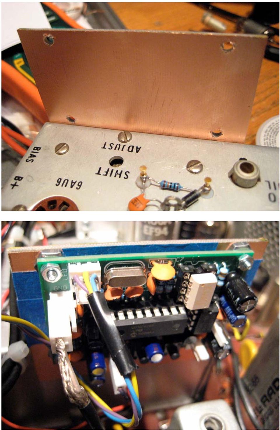
2 setscrews and remove the vernier. Set that in a safe place along with the panel mounting screws. Unsolder the three wires at the back of the VFO enclosure and unplug the VFO output cable. With a pencil I marked on the top of the VFO enclosure the wire colors that went to the feed through devices, W for the Bias, O for the B Plus and B for the Filament. [The wire colors were white, orange and brown.] Disconnect the SSB filter (and CW filter if installed). Remove the filter (s) from the L Bracket. Remove the L bracket by unloosening the two nuts. You will hear the two holding screws drop into the VFO enclosure. [Upon re-assembly I taped the screw heads to the chassis using masking tape. This will hold the screws in place until you can put the lock washers and nuts back on.] The reason the filter L Bracket must be removed is to provide access to two of the four bolts holding the VFO assembly on to the main chassis. Put the L Bracket and hardware in a safe place. Next remove the four nuts holding the VFO enclosure to the chassis and put the 4 lock washers and nuts in a safe place. [Long ago I purchased a multi compartment plastic box, which I use to collect the parts and hardware. It has been a lifesaver. This has greatly reduced lost parts and lost hardware.] Gently pull up and back on the VFO enclosure until it is free of the chassis. The underside of the VFO enclosure is open and provides ample room to make the necessary modification to the VFO. The VFO box could be further disassembled but I was unable to loosen the two setscrews that hold the internal vernier to the tuning capacitor. But in retrospect that was probably a good thing and in the final analysis not required. The first modification is to remove the fiber standoff that was originally a part of the dial correction zero set mechanism. The removal is necessary to provide clearance for the tri-color LED that will fit in the front panel hole. This LED is needed to observe the LOCK state. In the X-Lock-3 installation instructions several key points were made and this is where paying attention is important. Since a connection to the VFO tank circuit must be made, the caution here is to keep leads short and direct. Another caution is that there must be some diddling of the tank coupling capacitor to assure optimum operation. In practice you want the VFO to change frequency about 20 khz as a voltage from 0 to 12 VDC is applied to the 1N4004 Diode. Two capacitors were supplied with the kit, a 22 PF and a 68 PF. As is mentioned in the instructions a smaller value of capacitance may be required depending on the individual tank circuit components. I found that it only required 7 PF for the 20 khz shift based on where I connected the X-Lock-3 to the tank circuit. An adjustment to coil L941 must be made to reset the tuning range once the new cap is installed. So the questions are where to connect to the tank circuit and how do you do that so that frequency stability is not impacted. Refer to the two diagrams out of the Heathkit HW-101 manual to see where to put the holes and the second shows the connection point in the VFO circuit. Following are a series of photos that detail the actual modifications. In the first one I show where to locate the two holes as seen from the underside. The second shows the actual location of the two small holes fitted with the feed through and the anchor point.
![[The wire colors were white, orange and brown.] Disconnect the SSB filter (and CW filter if installed). Remove the filter (s) from the L Bracket. Remove the L bracket by unloosening the two nuts.](/docs-images/46/21725110/images/page_2.jpg "You will hear the two holding screws drop into the VFO enclosure. [Upon re-assembly I taped the screw heads to the chassis using masking tape.")
3 The third photo shows how the interface electronics following the X-Lock-3 are installed on the top of the enclosure. The fourth photo shows the schematic of where to install the 7 PF Silver Mica coupling capacitor. The fifth shows the install in the VFO.

4 Note that the feed through was made from a second standoff. I simply cut the insulating teflon about 1/16 inch from around the barrel and then cut a hole in the bottom of the teflon barrel. I was able to push the gold pin through the hole and there is a stop on the shaft to stop the shortened teflon barrel. Thus I had a connection points at either end. You can observe the shortened barrel and length of the gold post in the left feed through. On the underside of the feed through I soldered a very stiff wire as an anchor point since I would be testing various coupling caps and this enabled making component changes. A note about the feed through and the anchor point in terms of installation. When drilling the holes in the top of the chassis use a drill smaller than the Teflon barrel diameter. Then with a small fine round file carefully enlarge the hole while constantly testing if the teflon will fit into the enlarge hole. Stop just at the point where it almost fits and then press fit the feed through and anchor point so it is a tight fit. This will anchor them so there is no movement. This takes time to do so don t rush it! A solder lug was fitted to one of the screws which anchor the variable capacitor and this provided a convenient connection point for grounding the anode end of the 1N4004 and the 10 NF bypass cap. This arrangement provides for short component connection leads. This is a very stout install so there is no physical movement of the components. [Keep in mind where prior planning makes the job easier.]

5 Feed point from the X-Lock-3.

6 7 PF SM Stiff Wire At this point it would be a good idea to test the VFO with the modifications BEFORE reinstalling the unit back into the radio. This can be done in several ways. I happen to have a power supply that will supply 6.3 VAC and +108 VDC Regulated. I temporarily hooked up this supply to the VFO. To the 100K resistor at the supply end I applied a variable DC voltage of 0 to +12 VDC. Using a frequency counter connected to the output I was able to determine the optimal value of the coupling capacitor. Initially I started with the supplied 22 PF and running the DC voltage through its range found the Delta frequency change to be on the order of about 60 khz way too large. I then tried a 4.7 PF NPO capacitor and the Delta frequency change was only about 14 khz too small. So then I tried the 7 PF Silver Mica and that was almost exactly 20 khz which is what G4GXO suggested as optimal. So what do you do if you do not have the digital dial installed and do not own a frequency counter and don t have a special power supply? Improvise! You can make a short power cable of about two feet of wire and hook up the power cable to the HW-101 connection points and then connect to the VFO. Be sure to include a ground wire as the VFO gets its ground return through the metal to metal connection. In my case I have the digital dial installed and could have read the frequency by connecting a jumper cable from the VFO output port to the input on the HW-101 VFO input port. This gives a whole new meaning to remote VFO. But if you lack some sort of digital display or counter you can listen to the output on a general coverage receiver tuned to 5 MHz and listen for the VFO output. I did that too in addition to having the frequency counter on the

7 output. Once you are assured that the VFO is working and the frequency spread is as it should be disconnect the wiring and re-install the VFO in the reverse sequence. Start first by taping down the two screws that hold the L shaped crystal filter bracket. Next install the VFO enclosure etc. Now where to install the X-Lock-3 in the HW-101. As luck would have it there is a perfect place right on the VFO enclosure. This will keep the leads short while providing access to the X-Lock-3 for any on-board adjustments. The magic answer to install the X-Lock-3 is a piece of scrap double-sided copper PC Board. Along the left edge of the VFO enclosure are two large sheet metal screws that connect the two sections of the VFO enclosure. These provide anchor points to vertically mount the PC Board while at the same time the PC Board serves as a base plate to mount the X-Lock-3. There is nothing critical about the size of the PC Board other than it be large enough to hold the X-Lock-3 and provide a mounting lip to mount to the VFO enclosure. I used four large 6-32 nuts as spacers to elevate the X-Lock-3 from the mounting board. To assure no shorts I covered the PC Board with a layer of 3M masking tape. See below.

8
9 The above is a plan view of the X-Lock-3 installed along the right hand edge of the VFO enclosure and the yellow wire carries the correction voltage to the 1N4004. The circuit board along the left-hand edge is part of the signal level adjustment for the digital dial. The tri-color status LED has the normal 3-pin connector installed so it can plug onto the X-Lock-3. But I also installed an eight-inch long 3-wire cable to the X-Lock-3 board LED connector and put a mating plug on the end of the cable. This enables remote viewing of the status LED. I bent the LED at a right angle so it would fit in a panel mounted LED socket than now occupies the space where the Zero Set Control was located. I used some electrical tape around the exposed LED wires to prevent any shorts to the chassis. See below.

10

11 The next phase is to build the DC Power Supply to power the X-Lock-3. G4GXO recommends a supply voltage in the range of +10 VDC to no more than +16 VDC. The reason for the + 10 VDC is that the X-Lock-3 has two on board regulators, one at + 5 VDC and the other at + 8 VDC. You need a several volt differential to have the + 8 VDC regulator to work properly thus the + 10 VDC. On the other end you need a several volt differential to produce + 10 VDC. The source that was chosen was the 12.6 VAC filament supply that was run into a 1N4007 diode that is configured as a simple diode rectifier. Given the low current draw you would expect around 13 or so VDC coming from that rectifier which is more than ample to drive an LM317 Adjustable voltage regulator. By selecting two values of resistors it is possible to develop a whole array of fixed output, regulated voltages. There are calculators and look up tables on the Internet that give the values and expected outputs. I chose 220 Ohms and 1650 Ohms. With these values the LM317 outputs VDC perfect! Below is the schematic of the power supply to power the X-Lock-3. The LM317 has another function in that it will clean up the input signal, so that is a bonus. The power supply was built on a small piece of Radio Shack Perforated Board and mounted on the underside of the chassis.

12 In the Drake vacuum tube radios of the same vintage, that frequently had solid state as well as vacuum circuitry, the Drake engineers simply used dropping resistors off of the low voltage screen/plate supply. Needless to say there was a lot of heat just to get +12 VDC.

13 These are the two power supply boards, one for the digital dial and the other for thex- Lock-3. The one of the right is the X-Lock-3. It was difficult to find space on the underside of the HW-101 to add circuit boards. I found one spot where I could install two aluminum pillars approximately 3/8 inch high that were spaced the exact width of the Radio Shack Perforated Board. One of the pillars mounting holes was actually inside the PA cage. So as you can well understand measure 40 times and cut once. In order to utilize a single set of pillars to support both power supply boards, I notched the power supply board for the X-Lock-3 so that the board mounting holes could be utilized and yet the board itself not interfere with already installed components. If you look carefully at the top mounting screw you will see three diodes, which are all 1N4007. These three diodes are fed with 12.6 VAC from the filament rail to develop three separate DC voltages. The point is that I was able to make relatively short connections from the 12.6 VAC rail to the three supplies that are on the two boards. Measure 40 times and cut once. It was no accident that the boards were laid out this way! The three supplies develop 9.66 VDC and 5 VDC for the Digital Dial plus 10.5 VDC for the X-Lock-3. For those skilled at making printed circuit boards this of course would make the install much easier as a smaller footprint board could be developed. Below is a birds eye view of the bottom side of the HW-101 to give you a feel of the not too much available space to add circuit boards.

14 The last phase is the final integration and that is to simply connect the VFO input that was sampled from the lead going to HW101 circuit board. The power was connected to the X-Lock-3 and a lead was connected from the voltage correction pin to the correction circuit installed on the top of the VFO enclosure. At power on the status led goes through its start up sequence only it will blink red for several seconds the buffer stage following the solid state oscillator is a vacuum tube and will have no output until it is warmed up. Then it will lock green indicating that it is working. Now the digital dial reading does not move! One very nice feature of the X-Lock-3 is that operating CW. It is so cool to key the radio and see the digital dial display change to the CW offset frequency and then return to the stored frequency when you have completed the CW keying sequence. Thank you Ron for including this feature in the X-Lock-3! With the Digital Dial and the X-Lock-3 this is about a $120 upgrade. To breathe new life into an older vintage radio that is less expensive than buying a whole new radio! The X- Lock-3 kit costs about $55 as delivered from the UK and is well worth the cost. The digital dial once set on frequency does not move. The HW-101 by itself was a well - designed radio for its time. The updating of the radio with the known circuit improvements and addition of some current technology now makes the HW-101 a modern radio.

15 73 s Pete N6QW

ECEN 1400, Introduction to Analog and Digital Electronics
 ECEN 1400, Introduction to Analog and Digital Electronics Lab 4: Power supply 1 INTRODUCTION This lab will span two lab periods. In this lab, you will create the power supply that transforms the AC wall
Assembly Instructions: Shortwave Radio Kit
 Assembly Instructions: Shortwave Radio Kit MTM Scientific, Inc P.O. Box 522 Clinton, MI 49236 U.S.A Introduction Fig 1: The assembled Shortwave Radio Kit The SHORTWAVE RADIO KIT (#SWRAD) from MTM Scientific
GLOLAB Universal Telephone Hold
 GLOLAB Universal Telephone Hold 1 UNIVERSAL HOLD CIRCUIT If you have touch tone telephone service, you can now put a call on hold from any phone in the house, even from cordless phones and phones without
Modifying the Yaesu FT-847 External 22.625 MHz Reference Input
 Modifying the Yaesu FT-847 External 22.625 MHz Reference Input David Smith VK3HZ Introduction This document describes the modification of an FT-847 to allow an external 22.625 MHz Reference oscillator
Cumbria Designs T-1. SSB/CW Filter kit (4.9152MHz) User Manual
 User Manual") Cumbria Designs T-1 SSB/CW Filter kit (4.9152MHz) User Manual CONTENTS 1 INTRODUCTION 2 2 CIRCUIT DESCRIPTION 2 3 ASSEMBLY 2 4 TESTING 4 The Steading Stainton PENRITH Cumbria CA11 0ES UK 1 Introduction
Cumbria Designs T-1 SSB/CW Filter kit (4.9152MHz) User Manual CONTENTS 1 INTRODUCTION 2 2 CIRCUIT DESCRIPTION 2 3 ASSEMBLY 2 4 TESTING 4 The Steading Stainton PENRITH Cumbria CA11 0ES UK 1 Introduction
LS-1 Series Tungsten Halogen Light Sources Installation and Operation Instructions
 LS-1 Series Tungsten Halogen Light Sources Installation and Operation Instructions Description The LS-1 Series of tungsten halogen light sources are versatile, white-light lamps optimized for use in the
Time needed: ~3h for lid replacement only. Add 1h for operation harness in lid and ~2h more for installing drive unit and cable harness in trunk.
 DIY for replacing trunk lid and/or retrofitting electrical operation of trunk lid. This document is meant to be a support and give advice on the procedure but I will take no responsibility for any damage
EH-20 20m antenna. By VE3RGW
 EH-20 20m antenna By VE3RGW Equivalent circuit of EH-20 (prototype 2A) antenna system. Upper cylinder Lower cylinder Ground Counter pose Phasing coil Impedance transformer and tune circuit Tune coil Feed
OEM Manual MODEL 2350 ELECTRONIC DUAL CYLINDER SCALE
 OEM Manual MODEL 2350 ELECTRONIC DUAL CYLINDER SCALE Scaletron Industries, Ltd. Bedminster Industrial Park 53 Apple Tree Lane P.O. Box 365 Plumsteadville, PA 18949 USA Toll Free: 1-800-257-5911 (USA &
Odyssey of the Mind Technology Fair. Simple Electronics
 Simple Electronics 1. Terms volts, amps, ohms, watts, positive, negative, AC, DC 2. Matching voltages a. Series vs. parallel 3. Battery capacity 4. Simple electronic circuit light bulb 5. Chose the right
Glolab Talking Phone Dial Monitor
 Introduction The detects the tones generated when numbers are dialed on your touch tone telephone and speaks the numbers that were dialed. This verifies that you dialed the correct number and is especially
GLOLAB Two Wire Stepper Motor Positioner
 Introduction A simple and inexpensive way to remotely rotate a display or object is with a positioner that uses a stepper motor to rotate it. The motor is driven by a circuit mounted near the motor and
Elecraft K3 KPA3 Power Connector Replacement Revision A Review, April 16, 2012 Copyright 2012, Elecraft, Inc. All Rights Reserved
 Introduction Elecraft K3 KPA3 Power Connector Replacement Revision A Review, April 16, 2012 Copyright 2012, Elecraft, Inc. All Rights Reserved The connectors furnishing high current to the KPA3 module
Whale 3. User Manual and Installation Guide. DC Servo drive. Contents. 1. Safety, policy and warranty. 1.1. Safety notes. 1.2. Policy. 1.3. Warranty.
 Whale 3 DC Servo drive User Manual and Installation Guide Contents 1. Safety, policy and warranty. 1.1. Safety notes. 1.2. Policy. 1.3. Warranty. 2. Electric specifications. 2.1.Operation ranges. 3. Connections
Replacing the noisy cooling fan in ICOM IC-2KL by Bert Almemo, VE3OBU/SM7BUR
 Replacing the noisy cooling fan in ICOM IC-2KL by Bert Almemo, VE3OBU/SM7BUR The following describes how to replace the cooling fan for a quieter one in the IC-2KL with as little effort as possible. The
Post Mount Light Installation*
 Post Mount Light Installation* *For the general installation of most Post Mount Spotlights, many vehicles may need slight modifications to these instructions. You will need the following tools: High torque
BUILDING INSTRUCTIONS
 etap2hw 38 mm I2C to LCD Interface BUILDING INSTRUCTIONS October 2013 P. Verbruggen Rev 1.01 15-Oct-13 Page 1 Table of Contents Chapter 1 General Information 1.1 ESD Precautions 1.2 Further Supplies 1.3
Build A Video Switcher. Reprinted with permission from Electronics Now Magazine September 1997 issue
 Build A Video Switcher Reprinted with permission from Electronics Now Magazine September 1997 issue Copyright Gernsback Publications, Inc.,1997 BUILD A VIDEO SWITCHER FRANK MONTEGARI Watch several cameras
3. SEISCO PARTS & SERVICE REMOVAL AND REPAIR GUIDE
 4 3. SEISCO PARTS & SERVICE REMOVAL AND REPAIR GUIDE A. Changing the Control Board B. Replacing a Heating Element C. Thermistor Replacement D. High Limit Switch Replacement E. Level Detector Replacement
DIY Y6. Build Manual V.A 2014
 DIY Y6 Build Manual V.A 2014 1 Contents Thanks for purchasing a DIY Y6! These instructions will show you how to assemble a Y6 using the Pixhawk autopilot system and ArduCopter/APM:Copter firmware. If you
430 Power/Electronics Replacement
 Replacing the main board WARNING Before proceeding, turn off the main power switch and unplug the power cord. Caution Make sure you are properly grounded with an ESD strap before continuing. The main printed
73 Chevy C10 Ammeter to Volt Gauge Conversion Mark and Michael Olson 2013 Rev 1.0
 73 Chevy C10 Ammeter to Volt Conversion Mark and Michael Olson 2013 Rev 1.0 The ammeter in my son s 73 Chevy C10 did not work, so we decided to convert it to a more modern volt gauge. We made a number
INSTALLATION AND OPERATING INSTRUCTIONS For Model GL1 Gate Locks
 Securitron Magnalock Corp. www.securitron.com ASSA ABLOY, the global leader Tel 800.624.5625 [email protected] in door opening solutions INSTALLATION AND OPERATING INSTRUCTIONS For Model GL1 Gate
The $25 Son of a cheap timer This is not suitable for a beginner. You must have soldering skills in order to build this kit.
 The $25 Son of a cheap timer This is not suitable for a beginner. You must have soldering skills in order to build this kit. Micro Wizard has been manufacturing Pinewood Derby timers for over 10 years.
Homebuilt HF Radios for Use Underground Paul R. Jorgenson KE7HR
 Homebuilt HF Radios for Use Underground Paul R. Jorgenson KE7HR With the good success in using Amateur Band HF radio for underground communications, I started looking for cheaper alternatives to the $500+
SCREENLOGIC INTERFACE WIRELESS CONNECTION KIT
 SCREENLOGIC INTERFACE WIRELESS CONNECTION KIT FOR INTELLITOUCH AND EASYTOUCH CONTROL SYSTEMS INSTALLATION GUIDE IMPORTANT SAFETY INSTRUCTIONS READ AND FOLLOW ALL INSTRUCTIONS SAVE THESE INSTRUCTIONS Technical
ScreenLogic Wireless Connection Kit. Installation Guide. pool/spa control system
 pool/spa control system ScreenLogic Wireless Connection Kit Installation Guide P/N 520663 - Rev B 8 Technical Support Contact Technical Support at: Sanford, North Carolina (8 A.M. to 5 P.M.) Phone: (800)
A&A CORVETTE PERFORMANCE C6 BOOST & FUEL GAUGE INSTALLATION INSTRUCTIONS
 A&A CORVETTE PERFORMANCE C6 BOOST & FUEL GAUGE INSTALLATION INSTRUCTIONS 1. Check your gauges before you take them out of the packaging to make sure they are at 0 (zero) psi for both boost and fuel pressure.
SUPER SNOOPER BIG EAR
 AA-1D Super Snooper Big Ear SPECIFICATIONS Operates on 5 to 9v DC Will drive a small speaker Provides up to 1 watt of audio power Distortion > 0.2% Voltage Gain up to 46 db Size: 1 x 1.95 Rainbowkits.com
MGB Chrome Bumper Conversion
 MGB Chrome Bumper Conversion Installation Instructions For 1974 1/2-1980 MGB This kit requires cutting, welding, and painting. Professional installation recommended. Note: Every MGB body is slightly different
PowerFlex 700S and 700H Frame 12 DC Bus Connector Kit
 PowerFlex 700S and 700H Frame 12 DC Bus Connector Kit Installation Instructions This document provides instructions for the installation of a DC bus connector kit for PowerFlex 700S and 700H frame 12 drives
SYSTEM 4C. C R H Electronics Design
 SYSTEM 4C C R H Electronics Design SYSTEM 4C All in one modular 4 axis CNC drive board By C R Harding Specifications Main PCB & Input PCB Available with up to 4 Axis X, Y, Z, A outputs. Independent 25
DIY QUAD. Build Manual V.A 2014
 DIY QUAD Build Manual V.A 2014 1 Contents Thanks for purchasing a DIY Quad! These instructions will show you how to assemble a Quad using the Pixhawk autopilot system and ArduCopter/APM:Copter firmware.
200W DISCRETE POWER AMPLIFIER K8060
 H8060IP-1 200W DISCRETE POWER AMPLIFIER K8060 Ideal for active speaker system or subwoofer, guitar amp, home theatre systems, instrument amp, etc. Features & Specifications Specifications: Excellent value
MODEL 2202IQ (1991-MSRP $549.00)
") F O R T H E L O V E O F M U S I C F O R T H E L O V E O F M U S I C MODEL 2202IQ (1991-MSRP $549.00) OWNER'S MANUAL AND INSTALLATION GUIDE INTRODUCTION Congratulations on your decision to purchase a LINEAR
F O R T H E L O V E O F M U S I C F O R T H E L O V E O F M U S I C MODEL 2202IQ (1991-MSRP $549.00) OWNER'S MANUAL AND INSTALLATION GUIDE INTRODUCTION Congratulations on your decision to purchase a LINEAR
TOYOTA Tundra 2007 - BACK-UP CAMERA SYSTEM Preparation
 Preparation Part Number(s): PT233-34070, PT923-35070-11, PT923-35070-43 NOTE: Part number of this accessory may not be the same as part number shown. Back Up Monitor Kit Contents PT923-35070-11 / PT923-35070-43
ILISC515-A Shift Interlock (Manual Lift Door) 2015 Ford Transit, 3.7L and 3.5L
 2015 Ford Transit, 3.7L and 3.5L") An ISO 9001:2008 Registered Company ILISC515-A Shift Interlock (Manual Lift Door) 2015 Ford Transit, 3.7L and 3.5L Introduction The ILISC515-A is a microprocessor driven system for controlling wheelchair
An ISO 9001:2008 Registered Company ILISC515-A Shift Interlock (Manual Lift Door) 2015 Ford Transit, 3.7L and 3.5L Introduction The ILISC515-A is a microprocessor driven system for controlling wheelchair
Control Box Wiring For PRSstandard Tool
 888-680-4466 ShopBotTools.com Control Box Wiring For PRSstandard Tool Copyright 2016 ShopBot Tools, Inc. page 1 Copyright 2016 ShopBot Tools, Inc. page 2 Table of Contents Introduction:...5 Installation:...5
Kit 106. 50 Watt Audio Amplifier
 Kit 106 50 Watt Audio Amplifier T his kit is based on an amazing IC amplifier module from ST Electronics, the TDA7294 It is intended for use as a high quality audio class AB amplifier in hi-fi applications
User Manual. Instructions for installing the Sure Stitch on the Next Generation Quilting Frame. Parts Included:
 User Manual Instructions for installing the Sure Stitch on the Next Generation Quilting Frame. Parts Included: 1: Display Console 1: Control Box 2: Encoder (Wires attached) (Not Shown) 1: 5v Power Supply
STEADYfast Stabilizer Installation Notes Fifth Wheel and Travel Trailers 11/23/13
 STEADYfast Stabilizer Installation Notes Fifth Wheel and Travel Trailers 11/23/13 (See Supplemental Instructions for trailers with heavy duty round footplates and/or Power Leveling Systems) PHONE SUPPORT
Joule Thief 3.0 Kit. June 2012, Rev 1 1 http://www.easternvoltageresearch.com Joule Thief 3.0
 Kit Instruction Manual Eastern Voltage Research, LLC June 2012, Rev 1 1 http://www.easternvoltageresearch.com HIGH BRIGHTNESS LED THIS KIT USES A 1W CREE, HIGH BRIGHTNESS LED. DO NOT STARE AT THIS (OR
Table of Contents. www.hunterfan.com. What to Expect with. Preparation. Tools Needed. Wiring. Hanging the Fan. Blades. Motor Housing.
 www.hunterfan.com Table of Contents What to Expect with Your Installation 30 inches Hanging the Fan Wiring 8 Maintenance, Operation & Cleaning Light Kit 13??? 14 1 9 Troubleshooting 11 5 Blades Motor Housing
RADIO AGE. The Newsletter of the Mid-Atlantic Antique Radio Club. Atwater Kent Variometers, Variocouplers, and Related Devices
 RADIO AGE The Newsletter of the Mid-Atlantic Antique Radio Club Volume 30 December 2005 Number 12 Atwater Kent Variometers, Variocouplers, and Related Devices BY RAY THOMPSON AND LEIGH BASSETT 2005, RAY
DDS VFO CONSTRUCTION MANUAL. DDS VFO Construction Manual Issue 1 Page 1
 DDS VFO CONSTRUCTION MANUAL DDS VFO Construction Manual Issue 1 Page 1 Important Please read before starting assembly STATIC PRECAUTION The DDS VFO kit contains the following components which can be damaged
TEACHING RESOURCES SCHEMES OF WORK DEVELOPING A SPECIFICATION COMPONENT FACTSHEETS HOW TO SOLDER GUIDE GET IN TUNE WITH THIS FM RADIO KIT. Version 2.
 TEACHING RESOURCES SCHEMES OF WORK DEVELOPING A SPECIFICATION COMPONENT FACTSHEETS HOW TO SOLDER GUIDE GET IN TUNE WITH THIS FM RADIO KIT Version 2.0 Index of Sheets TEACHING RESOURCES Index of Sheets
VOYAGER 570G. 744A Sprayer Control
 VOYAGER 570G 744A Sprayer Control U S E R M A N U A L U S E R M A N U A L Table of Contents CHAPTER 1 - INTRODUCTION...1 SYSTEM CONFIGURATIONS...1 KIT CONTENTS...3 CONTROL HOUSING ASSEMBLY...5 CHAPTER
Using and Wiring Light Emitting Diodes (LEDs) for Model Railroads
 for Model Railroads") Using and Wiring Light Emitting Diodes (LEDs) for Model Railroads LEDs have many useful applications in Model railroading, including: Locomotive headlights Rear-end warning lights for cabooses and passenger
Using and Wiring Light Emitting Diodes (LEDs) for Model Railroads LEDs have many useful applications in Model railroading, including: Locomotive headlights Rear-end warning lights for cabooses and passenger
Optical Sensor Interface for AFX Digital LED Timer/Counter by George Warner, Jan. 2003 [email protected]
 Optical Sensor Interface for AFX Digital LED Timer/Counter by George Warner, Jan. 200 [email protected] Abstract This paper presents a design for an optical sensor interface to an AFX Digital LED Timer/Counter.
POWER WAVE 455M/STT & (CE)
") Illustration of Sub Assemblies Illustration of Sub Assemblies Illustration of Sub Assemblies Illustration of Sub Assemblies P-450 P-450 PARTS LIST FOR POWER WAVE 455M/STT & (CE) P-450-A P-450-A ILLUSTRATION
Illustration of Sub Assemblies Illustration of Sub Assemblies Illustration of Sub Assemblies Illustration of Sub Assemblies P-450 P-450 PARTS LIST FOR POWER WAVE 455M/STT & (CE) P-450-A P-450-A ILLUSTRATION
Lathe Milling Attachment
 Lathe Milling Attachment By L C. MASON BY CLEVERLY stacking cold-rolled flat stock together, T-slots and slide for this lathe milling attachment are made without costly machinery. In fact, only two tools,
PUSH BUTTON START INSTALLATION MANUAL
 PUSH BUTTON START INSTALLATION MANUAL ALTHOUGH THIS PRODUCT HAS BEEN THOROUGHLY TESTED KPIERSON TECHNOLOGIES ASSUMES NO RESPONSIBILITY FOR ANY DAMAGE THAT MAY RESULT BY THE INSTALLATION OF THIS PRODUCT.
OPL BASIC. Dosing System for Professional Laundry machines. Contents
 OPL BASIC Dosing System for Professional Laundry machines Contents 1 Getting Started. Page 2 2 Installation. Page 4 3 Set Up & Operation. Page 8 4 Maintenance & Accessories. Page 10 5 Troubleshooting Page
Building the HVPS High Voltage Power Supply
 Introduction Building the HVPS High Voltage Power Supply Voltages higher than the LVPS provides kilovolts are needed in later experiments to get strong electric fields and to generate microwaves. The high-voltage
ADDING AN ELECTRIC AUXILIARY FAN TO RADIATOR STACK ON 03 ALPINE COACH
 ADDING AN ELECTRIC AUXILIARY FAN TO RADIATOR STACK ON 03 ALPINE COACH The original design of the 03 Alpine Coaches (and perhaps other years as well) did not include any kind of engine fan engage mechanism
Step by step guide to installing your own Ku Band satellite dish
 Step by step guide to installing your own Ku Band satellite dish If you don't feel comfortable installing your own system, your local TV Aerial or Handyman can easily follow these helpful guidelines for
TECHNICAL BULLETIN ALL S2 CX S. BEHR Heater system: modifications
 page CX, BEHR heating unit, level 3 modification:. The heating fan motor (935) (Bosch CPB 2V 23.404) can be swapped by, i.e. a Bosch DPD 2V 3.26.7 double fan motor from a BMW5??. One of the shaft ends
I Click on a link tab to jump to that page. Cover Page
 Publication, Duplication, or Retransmission Of This Document Not Expressly Authorized n Writing By The nstall Doctor s Prohibited. Protected By U.S. Copyright Laws. 1997,1998,1999,2000. Factory Radio Other
A CW QRP Transceiver for 20 m band. How it works I'll describe individually the three boards and the relative tuning devices.
 A CW QRP Transceiver for 20 m band The little QRP presented in this article may be built in a gradual manner, in fact it is divided in two main modules (plus VFO), you may also complete only a single part
P150SC15. Designed for 2015 Ford F150 Super-Cab and Super-Crew vehicles without Sony System. 2015 Stillwater Designs P150SC15-A2-20150813
 P150SC15 Designed for 2015 Ford F150 Super-Cab and Super-Crew vehicles without Sony System Subwoofer Assembly Amplifier Assembly Amplifier Harness 2015 Stillwater Designs P150SC15-A2-20150813 M6 Bolt M6
INSTALLATION INSTRUCTIONS
 Rear Vision System Aftermarket and Factory 5.0, 8.4 and 6.1 MyGig Touch Screen Display (Factory Display requires Chrysler/Dodge dealer to activate) 2009 Current* Dodge Ram (Kit part number 1009-6503) *NOTE:
Installation Guide for Artic Air 24 Volt R134A Air Conditioner
 Installation Guide for Artic Air 24 Volt R134A Air Conditioner Rev 004 April 20, 2014 There are five objectives to installing the Artic Air unit: 1) The primary wiring from the battery, 2) The controller
WD7S PRODUCTIONS HIGH VOLTAGE POWER SUPPLY BOARD HV-2
 HIGH VOLTAGE POWER SUPPLY BOARD WARNING WARNING WARNING THIS POWER SUPPLY USES LETHAL VOLTAGES THIS IS NOT A BEGINNERS PROJECT!! IF YOU HAVE NEVER WORKED WITH HIGH VOLTAGE BEFORE, SEEK ANOTHER S ADVICE
INSTALLATION INSTRUCTIONS FOR G205 AND G207 STICK GRIPS
 1341 Distribution Way STe 15, Vista, A 92081 USA Ph 760.599.4720 Fx 760.599.4383 INSTALLATION INSTRUTIONS FOR G205 AND G207 STIK GRIPS G205 G207 Warning: Installation and use of Ray Allen ompany products
How To Power A 12 Volt Relay On A Car Or Truck
 Relay modification for older bikes Please read this in conjunction with the schematics at the end. All the options are shown, but you can opt to do any one or more as you wish. The electrical connections
Service Guide. Gateway M275
 Service Guide Gateway M275 Contents Replacing Gateway M275 Components.................................... 1 Identifying the convertible tablet PC model...................................... 2 Identifying
K6002 TEMPERATURE CONTROLLER. Specifications
 Total solder points: 169 + 99 + 67 Difficulty level: beginner 1 2 3 4 5 advanced TEMPERATURE CONTROLLER K6002 Unlike a normal thermostat, this kit has two outputs, one for "high" alarm and one for "low"
Cover Page. Factory Radio Other Documents Available For This Vehicle:
 & nstall Publication, Duplication, or Retransmission Of This Document Not Expressly Authorized n Writing By The nstall Doctor s Prohibited. Protected By U.S. Copyright Laws. 1997,1998,,2000. Factory Radio
Owners & Installation Manual for the Sheridan, Mountainair, Pine Valley and Old Forge Ceiling Fan Family
 Owners & Installation Manual for the Sheridan, Mountainair, Pine Valley and Old Forge Ceiling Fan Family Part of the Kiva Lighting Family Custom Lighting and Fans Since 1992 1312 12th St NW Albuquerque,
WPR400 Wireless Portable Reader
 P516-098 WPR400 Wireless Portable Reader User guide Para el idioma español, navegue hacia www.schlage.com/support. Pour la portion française, veuillez consulter le site www.schlage.com/support. Contents
Assembly Notes. Disclaimer:
 Assembly Notes Before you start building your kit, please take time to read the manual in full at least once to enable you to fully understand the procedures and avoid any mistakes. The following notes
Yaesu FT-736R PSU repair
 Yaesu FT-736R PSU repair Updated for DigiKey (North American) sources & data I gratefully acknowledge OZ1DB and his original repair documentation and DL7VHF for his schematic diagrams The built in AC/DC
HP 8970B Option 020. Service Manual Supplement
 HP 8970B Option 020 Service Manual Supplement Service Manual Supplement HP 8970B Option 020 HP Part no. 08970-90115 Edition 1 May 1998 UNIX is a registered trademark of AT&T in the USA and other countries.
12-Volt Negative Ground Installation Instructions
 12-Volt Negative Ground Installation Instructions For Part Number: 1141, 1164, 1165, 1181 CAUTION!!! Before installing, please read the following important information... 1. The Ignitor is designed for
BURGLAR ALARM KIT MODEL K-23. Assembly and Instruction Manual ELENCO
 BURGLAR ALARM KIT MODEL K-23 Assembly and Instruction Manual ELENCO Copyright 2013, 1989 ELENCO Electronics, Inc. Revised 2011 REV-Q 753223 No part of this book shall be reproduced by any means; electronic,
Before installation it is important to know what parts you have and what the capabilities of these parts are.
 INSTALLATION GUIDE Before installation it is important to know what parts you have and what the capabilities of these parts are. The Recon XZT is the smallest and most powerful gauge of its kind. With
TraceTek TTDM Series Leak Detection and Location Modules Replacement Parts Installation Instructions
 TraceTek TTDM Series Leak Detection and Location Modules Replacement Parts Installation Instructions TRACETEK TraceTek TTDM Replacement Parts General Information These instructions detail the steps to
4.3-inch Back-Up Camera
 TM 4.-inch Back-Up Camera Model No.: PKC0BU4 Owner s Manual and Warranty Information Read these instructions completely before using this product. Retain this Owner s Manual for future reference. INTRODUCTION
DIGITAL WARMING CABINETS
 DIGITAL WARMING CABINETS INSTALLATION-OPERATION-MAINTENANCE USER MANUAL Mac Medical 820 S Mulberry St. Millstadt, IL 62260 California OSHPD Pre-approved (618) 476-3550 phone (618) 476-3337 fax December
BMD16N-SD. version 1.2
 BMD16NSD version 1.2 Feedback decoder with 16 contacts with integrated current detection for the S88bus Compatible with a.o. Märklin Digital, Uhlenbrock Intellibox, Fleischmann TwinCenter and LDT HSI88
SB-C-CTS/10TW3 SKU# 94552 2008 & Up Cadillac CTS/CTS-V
 INSTALLATION GUIDE for the SB-C-CTS/10TW3 SKU# 94552 2008 & Up Cadillac CTS/CTS-V If you choose to perform the installation yourself, it is absolutely vital that the Stealthbox be properly mounted to the
M-9424-463V Intake Manifold INSTALLATION INSTRUCTIONS
 Please visit www.fordracingparts.com for the most current instruction information!!! PLEASE READ ALL OF THE FOLLOWING INSTRUCTIONS CAREFULLY PRIOR TO INSTALLATION. AT ANY TIME YOU DO NOT UNDERSTAND THE
Battery Charger For Nickel Cadmium and Nickel-Metal Hydride Rechargeable Batteries Model PSN Series
 Battery Charger For Nickel Cadmium and Nickel-Metal Hydride Rechargeable Batteries Model PSN Series Operating Instructions WARNING CONCERNING THE REMOVAL OF COVER: CAUTION: TO PREVENT THE RISK OF ELECTRIC
SYMMETRIC 1A POWER SUPPLY K8042
 SYMMETRIC 1A POWER SUPPLY K8042 Low cost universal symmetric power supply ILLUSTRATED ASSEMBLY MANUAL H8042IP-1 Features & Specifications Features low cost universal symmetric power supply just add a suitable
Building the AMP Amplifier
 Building the AMP Amplifier Introduction For about 80 years it has been possible to amplify voltage differences and to increase the associated power, first with vacuum tubes using electrons from a hot filament;
Projector90 Xenon Headlight Installation Guide
 Projector90 Xenon Headlight Installation Guide Written exclusively for Umnitza s Projector90 Product This step-by-step guide is designed to be used in together with other available documentation including
Power Window/Power Lock Installation. To begin with you will need all the parts listed below:
 Power Window/Power Lock Installation To begin with you will need all the parts listed below: From Donor Fiero: Fiero power window regulators Power window motors (Generic GM type part) -motors are riveted
Roof Top Air Conditioner INSTALLATION AND OPERATING INSTRUCTIONS
 Roof Top Air Conditioner INSTALLATION AND OPERATING INSTRUCTIONS Ducted System RECORD THIS UNIT INFORMATION FOR FUTURE REFERENCE: Model Number: Serial Number: Date Purchased: This manual must be read and
INSTALLATION MANUAL. Installation Instructions
 INSTALLATION MANUAL Power-Pole Signature Series Shallow Water Anchor Installation Instructions CAUTION: Read this instruction manual carefully. Become familiar with the controls and know how to operate
AstroSystems Digital Setting Circles for Zhumell, GSO, Apertura and Astro-Tech
 AstroSystems Digital Setting Circles for Zhumell, GSO, Apertura and Astro-Tech Components 1 Sky Commander Digital Setting Circle Computer 2 Encoders 10,000 step 1 Sky Commander Digital Setting Circle Manual
The basic set up for your K2 to run PSK31 By Glenn Maclean WA7SPY
 The basic set up for your K2 to run PSK31 By Glenn Maclean WA7SPY I am by no means an expert on PSK31. This article is intended to help someone get on PSK31 with a K2. These are the things I did to get
Bose Model 1801/1800 Power Amplifier
 SUPPLEMENT Bose Model 1801/1800 Power Amplifier Q4, part number 102428 and Q5, part number 102429 are no longer available with the lead length needed for soldering to the PCB. Use the part numbers listed
Model 201 Wiegand Touchpad Reader Installation Guide
 Model 201 Wiegand Touchpad Reader Installation Guide P/N 460353001C 15AUG11 2011 UTC Fire & Security. All rights reserved. This document may not be copied in whole or in part or otherwise reproduced without
JANUS INTERNATIONAL CORPORATION INSTALLATION INSTRUCTIONS Pantheon Mini Operator
 JANUS INTERNATIONAL CORPORATION INSTALLATION INSTRUCTIONS Pantheon Mini Operator The Janus Pantheon mini operator does not typically require the provision of any additional site requirements other than
Advantium 2 Plus Alarm
 ADI 9510-B Advantium 2 Plus Alarm INSTALLATION AND OPERATING INSTRUCTIONS Carefully Read These Instructions Before Operating Carefully Read These Controls Corporation of America 1501 Harpers Road Virginia
BUILT-IN DISHWASHER INSTALLATION INSTRUCTIONS
 BUILT-IN DISHWASHER INSTALLATION INSTRUCTIONS PLEASE READ COMPLETE INSTRUCTIONS BEFORE YOU BEGIN LEAVE INSTALLATION INSTRUCTIONS AND USER'S GUIDE WITH OWNER ALL ELECTRIC WIRING AND PLUMBING MUST BE DONE
OWNER S MANUAL. Permolock C3. Docking system for Power wheelchair in vehicle
 OWNER S MANUAL US Permolock C3 Docking system for Power wheelchair in vehicle How to contact Permobil Head Office of the Permobil group Permolock C3 Docking system for electric wheelchair in vehicle Produced
Lab 1: The Digital Oscilloscope
 PHYSICS 220 Physical Electronics Lab 1: The Digital Oscilloscope Object: To become familiar with the oscilloscope, a ubiquitous instrument for observing and measuring electronic signals. Apparatus: Tektronix
Alfa Romeo 147 On board instruments installation guide
 Alfa Romeo 147 On board instruments installation guide Alfa Romeo 147 On board instruments installation guide This guide is describing how I installed oil temperature and oil pressure gauges to my Alfa