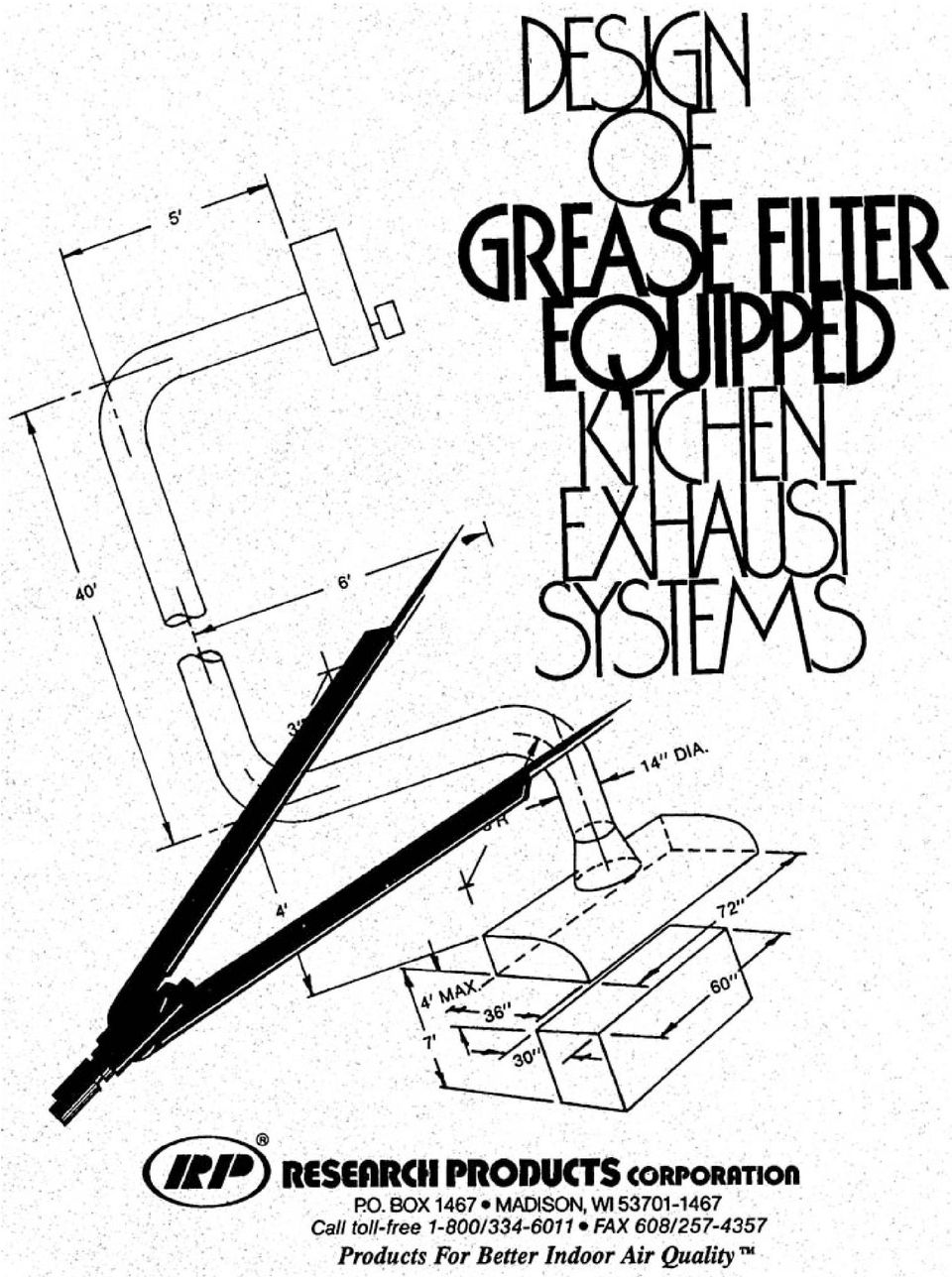
DESIGN OF GREASE FILTER EQUIPPED KITCHEN EXHAUST SYSTEMS
|
|
|
- Arline Walker
- 9 years ago
- Views:
Transcription
1
2 DESIGN OF GREASE FILTER EQUIPPED KITCHEN EXHAUST SYSTEMS CONTENTS PAGE NO. HOODS, WHY? 2 GREASE FILTERS, WHY? 2 TYPES OF HOODS 3 Ventilator Hood 3 Canopy Hood 4 Canopy Slot Hood 5 DESIGNING THE KITCHEN EXHAUST SYSTEM 6 Step No. I Hood 6 Step No. 2 Air Volume 6 Step No. 3 Filters Required 6 Step No. 4 Exhaust Duct 7 Step No. 5 Resistance to Airflow 8 MAKE-UP AIR 9 CODES 10 ACCESSORY ITEMS 10 SUMMARY 11 SAMPLE PROBLEM DRAWING 11 SAMPLE CALCULATION 12 CALCULATION SHEET 13 The need for a well designed grease filter equipped kitchen exhaust system has become widely recognized. Authoritative organizations, as well as local fire and health inspectors and industrial commissions, realize its importance. The properly designed exhaust system encourages better working conditions and, therefore, improves employee efficiency. HOODS, WHY? The purpose of the hood is to capture, as nearly as possible, all the heat, smoke, odors, grease and grease vapors produced in the cooking process and to contain them until the fan can exhaust them. GREASE FILTERS, WHY? Frequently, flash fires originating from cooking operations spread from the stove to grease deposits in the exhaust system. Non-filtered systems are prone to collect accumulations of highly combustible grease deposits throughout the entire duct system. Because of the chimney effect created in a vertical ductwork, a very intense rapidly spreading fire can engulf the entire system. A filtered system is protected from extensive damage because baffle type RP grease filters are designed to allow grease run off or the grease quantities collected on the mesh type filter is limited to that collected between cleaning. The buildup of extensive grease deposits in out of sight inaccessible locations is limited to the very small amount that passes through the filters (with efficient grease filters, usually less than 10%). Grease filters protect exhaust equipment. When filters are not used in the exhaust system, grease will collect on the blower wheel and motor. This is detrimental in many ways. Grease deposits on the wheel will cause unbalance resulting in unnecessary bearing wear. Grease accumulations on the motor will cause overheating which will create an additional fire hazard. The grease also has a tendency to deteriorate the insulation on wires thus adding another fire hazard. Research Products Corporation

3 Baffle type RP grease filters simplify the cleaning process because most of the grease deposits run off the baffles to a collection device. (The mesh type grease filters collect the deposits on the filter in an easily accessible area.) Minimum cleaning problems promote regular cleaning; thus safety, sanitation, and health standards are greatly improved. Grease filters have established themselves as an extremely important part of any kitchen exhaust system. In many areas, they are required by law. They should be included in any newly designed hoods and incorporated in remodeled hoods. The design and selection of grease filters play an important role in the overall effectiveness of the entire kitchen exhaust system. The exhaust air volume through a ventilator hood will vary from approximately 300 to 350 cfm per lineal foot of hood length. If a hood of this type is being considered, the manufacturer should be consulted. TYPES OF HOODS There are two basic hood types: 1. Ventilator or back shelf hood. 2. Canopy type hood. a. Canopy - island hood. b. Canopy - wall hood. c. Canopy - corner wall hood. d. Canopy - slot type hood. VENTILATOR OR BACK SHELF HOOD The ventilator or back shelf hood (Figure I) is designed to be as close as possible to the cooking surface, usually 18 to 24 inches above it. Heat and fumes are caught close to the point of origin. The entrainment velocity moves the air under the shelf away from the cook. The design details of ventilators and auxiliary equipment are generally furnished as a package by the manufacturer of this type of equipment. Various patented features may be included. Usually the hood is pre-assembled, then installed according to manufacturer's recommendations. The design of the hood will not be covered in this brochure because of this fact; however, the filter, the fan, motor and ductwork are basically the same as the canopy type hood covered in detail later in the text. 3

4 CANOPY HOODS The more commonly used canopy hoods have several variations. Figures 2a, b, and c, show the three basic variations of this hood design. Fig. 2a CANOPY-ISLAND type with 4 sides exposed. Fig. 2b CANOPY-WALL type with 3 sides exposed. Fig. 2c CANOPY CORNER type with 2 sides exposed. The canopy type hood, since it is by far the most widely field fabricated, will be used as the hood in the step-by-step design problem that we will develop. 4

5 Fig. 2d CANOPY-SLOT type hood. An example lay-up and filter placement for a typical hood is shown. The slot type hood is not primarily designed for the commercial kitchen exhaust system; however, it is periodically called for by the design engineer. This hood is also sometimes called a double cavity hood or just plain slotted hood. There are potential problem areas when utilizing a hood of this design. The heat generated in the cooking process is not exhausted as rapidly as in the conventional design. Filter placement and good fit are difficult in a hood of this design. The cleanability of the filters, as well as the cleanability of the entire hood cavity becomes more difficult with this design. If the canopy-slot type hood is to be used, it has its greatest value in the extremely large island type (4 sided exposed) hood design. The greatest asset of this type hood is the removal of smoke and grease contaminants with the minimum exhaust requirement. However in many applications more ventilation air is required than exhausted, so the prime reason for having this type hood is lost. The hot contaminated air rises from the cooking surface and is held in the hood cavity until such time as it can be removed through the slot that goes completely around the perimeter of the hood. Two important design considerations are (I) have the hood as low as possible over the cooking surface and (2) extend the hood out 6 inches minimum beyond the edge of the cooking surface, Typical hood construction would have a 2 to 4 inch slot around the entire perimeter of the hood. The air velocity through this slot is normally between 350 and 450 fpm. The placement and choice of filters is important to assure optimum airflow through them. Optimum operating velocities for the baffle type grease filter is 300 fpm. Optimum operating velocities for the mesh type grease filter is 350 fpm. This will make it necessary to blank off several areas in the filter rack to increase the air speed through the filter area. Lack of field information and design criteria for this type hood limits its use. 5

6 Designing the Kitchen Exhaust System (See Sample Problem) Following is an example of the recommended step-by-step procedure for the design of a grease filter equipped kitchen exhaust system. Critical specifications to be determined are: 1. Dimensions of the hood. 2. Volume of air to be exhausted. 3. Number of filters required. 4. Diameter of the duct from the hood to the point of discharge. 5. Resistance against which the blower must exhaust the calculated volume of air. 6. Make-up air. 7. Codes. STEP 1 TO DETERMINE DIMENSIONS OF THE HOOD The dimensions of the base of the hood are larger than the cooking surface it covers to adequately remove the contaminants generated in the cooking process. A general rule that has proven very satisfactory is summarized as follows: The length and width of the hood base should equal the overall dimension of the appliances it covers plus a 6 inch minimum overhang on each side of the equipment that is not enclosed by an apron or an adjacent wall. The distance from the base of the hood to the cooking surface will normally be 3 to 4 ft. since the kitchen employees must work underneath the hood. Excessive clearance between the cooking surface and hood hampers the effectiveness of the exhaust system and should be avoided. Four feet is maximum. STEP 2 VOLUME OF AIR TO BE EXHAUSTED The volume of air to be exhausted is governed by state or local codes. If no code exists, the total quantity of air (cfm) to be exhausted from the hood shall be determined by one of the following formulae: For canopy hoods less than 8 feet long: cfm = 150 A (for hoods open all sides) cfm = 100 A (for hoods open 3 sides or less) For canopy hoods 8 feet or longer: cfm = 200 P Note: cfm = 200 P was derived from the formula cfm = 50 PD and establishing D as 4 feet (cfm = 50 x P x 4 = 200 P) "cfm" - shall mean the total quantity of air required to be exhausted by the ventilating system in cubic feet per minute. 'A' - shall mean the cross section of the plane extending over the canopy hood opening in square feet. "P" - shall mean the perimeter of the open sides of the hood. "D" - shall mean the distance between the cooking surface and the face of the hood. The volume figures should be somewhat higher for charcoal and charcoal type cooking. Some city codes demand double exhaust volumes for these cooking areas. STEP 3 NUMBER OF FILTERS REQUIRED It is important to select the proper number of the correct size grease filters of a reputable make. Too many filters increase cost. Too few filters increase the resistance to airflow and also increase the filter cleaning frequency. Optimum operating velocity range for the baffle type PIP grease filter is fpm. Optimum operating velocity for the mesh type grease filter is 350 fpm. The number of filters required in the hood can be determined by dividing the total volume of air to be exhausted by the cfm rating of the filters. The manufacture's optimum rating should be used (see Table I). The use of standard size filters is advisable from a cost, delivery, and replacement standpoint. Any space in the hood not 6

7 filtered should be blanked-off with sheet metal. It is important to install filters at the ends of the hood; however, grease filters should not be installed directly over a broiler flue, or any other flue from kitchen cooking equipment. The hot gases would make filters very difficult to clean and could damage them. The blanked off space, if required, should be divided equally between the filters. This will ensure optimum performance and will equalize the air velocity over the entire length of the hood opening. TABLE I BAFFLE TYPE Nom. Size (Max.)Rating (cfm) 20H x 25W H x 20W H x 25W H x 20W 525 I OH x 20W H x 16W H x 20W 865 MESH TYPE Nom. Size Opt. Rating (cfm) 20x x x x x x The hood itself must be deep enough to permit the installation of the grease filters at a minimum 45 degree angle from the horizontal. This will eliminate grease globules dropping back onto the cooking surface. A design of this type also permits enough volume in the hood so that unusually large "puffs" of steam and greasy vapors have a place to accumulate until the exhaust fan can remove them. This design also allows mixing of room air with the hot air over the cooking area. Proper design keeps the temperature at the filters less than 200 degrees F. and reduces the possibility of accumulated grease run off or vaporizing and passing through the filters. There isn't a grease filter made that will effectively remove vapors. Assuming the temperature at the filters is less than 200 degrees F., the grease deposits will be brownish and easily removed. Above 200 degrees F., the deposits tend to bake on the filter, darkening in color, and are extremely difficult to remove. The baffles of the baffle type RP grease filters must be positioned vertically, not horizontally. There must be a positive air seal around the perimeter of the grease filter and each baffle type grease filter must be retained on the downstream side. Most filters are designed so that the accumulated grease will run down the face of the filter and drop from the lowest edge into a drip tray Drip tray should be pitched to drain to an enclosed metal container having a capacity not exceeding one gallon. (ref.nfpa No. 96) Some codes suggest that the minimum height from the cooking surface to the lower edge of the grease filter should not be less than: a. No exposed flames - grills, trench fryers, etc. - 2½ ft. b. Exposed charcoal and charcoal type fires - 4½ ft. c. Exposed fires other than b. - 3½ ft. STEP 4 DESIGN OF THE EXHAUST DUCT The duct leading from the kitchen exhaust air is discharged must be correctly sized. The velocity of the exhaust air must be high enough to minimize condensation on the various parts of the duct system; however, avoid the use of excessively high air velocities because of the resulting noise. Also, more power is required to drive the blower. It is important to discharge the air at a location that will not cause discomfort to the people in the vicinity or damage surrounding property. The bends and elbows of the ductwork should be kept at a minimum. When elbows are used, a radius of 2 to 2½ times the duct diameter is recommended. This will minimize the resistance against which the blower must move the air. The duct take-off at the top of the hood should be transitioned. This will reduce the entrance loss and resistance offered to airflow at the entrance point. If the hood length exceeds 10 ft., it is desirable to have two discharge ducts from the top of the hood join the main exhaust duct. These should also be transitioned where they join the hood. This ensures good air distribution throughout the entire hood area. Two thousand (2000) ft. per minute velocity should be used to determine the duct diameter, unless otherwise specified. The area of the duct (sq. ft.) can be calculated by dividing the total exhaust cfm by 2000 fpm. This duct area is converted to a diameter in Table II. 7

8 Table II can also be used to determine the branch duct size if more than one discharge duct is required. Divide the total volume of air to be exhausted by the number of branches to determine the cfm per branch. Then divide the cfm per branch by 2000 fpm to give the sq. ft. area which can be converted to a duct diameter. TABLE II Friction Loss/ Duct Area Duct Diameter Ft. of Duct (Sq. Ft.) (Inches) (Inches W.G.) DUCT CONSTRUCTION See National Fire Protection Association Standard No. 96, Ventilation of Restaurant Cooking Equipment for more information. Important considerations in duct construction are: 1. A circular duct requires a smaller space. If rectangular ducts are used, they should be as nearly square as possible. 2. The duct should be constructed of 16 gauge or heavier steel (see NFPA #96). 3. A minimum of 18" clearance should be provided from unprotected combustible construction. (See NFPA #96, Appendix B, for clearance from protected construction.) 4. All seams and joints shall have a liquid tight continuous external weld. 5. Exhaust ducts from kitchen hoods must be independent and not connected with any other ventilating system. 6. An opening shall be provided at each duct direction change for inspection and cleaning. 7. Vertical risers should be located outside the building and adequately supported by the exterior building wall. When risers must be located within the building, they should be enclosed in a continuous enclosure (see NFPA #96). A base residue trap should be provided on all risers. Exhaust ducts should not pass through fire walls or fire partitions. STEP 5 RESISTANCE AGAINST WHICH THE BLOWER EXHAUSTS THE CALCULATED VOLUME OF AIR It is essential that the blower selected meet the following two requirements: A. It must exhaust the calculated volume of air. B. It must exhaust this air against the maximum resistance encountered in the entire kitchen exhaust system. While the use of a propeller type fan may be tempting, they normally do not work well against the resistance encountered in a commercial kitchen exhaust system. The use of a blower for best results is strongly recommended. To conserve the exhaust air, a 2 speed motor is suggested. Low speed can be used during the "off," or low production time, and the high speed for peak production loads. Other factors that might influence the selection of a blower are location, space limitations, permissible noise level, installation and operation costs; however, A and B are the primary requirements. The system resistance calculations are based on normal room temperature. In those cases where air temperatures are increased significantly by the heat input from the appliances under the hood, consult the ASHRAE Guide for more detailed information on sizing ductwork and blowers for the specific temperatures involved. This resistance is usually assumed to be the total of the following four items: 1. The resistance of the grease filter is based on the manufacturer's rating. A value of.2 in. w.g. is ample for the mesh type filters. Use.56 in. w.g. for baffle type RP grease filters. 2. "The entrance loss" resistance occurring where the exhaust duct attaches to the hood will be approximately. I" water gauge when the exhaust duct velocity is approximately 2000 fpm. The opening at the hood and discharge duct should be transitioned as shown by the hood sketches on the calculation sheet. 3. The resistance from wind currents at the exhaust opening will vary anywhere from.i" to.5" water gauge depending upon the type and location of the outlet and on local wind conditions..5 inches is a maximum figure and should be used only if the exhaust is directly into the prevailing winds. Normally, something substantially less will be used..2" water gauge is satisfactory in most installations. 8

9 4. The resistance of the duct system is the total of all the straight duct, plus the elbows and bends expressed in equivalent length of straight duct. The total of the two sums is then multiplied by the friction loss per foot for the duct size and air velocity involved. Table II can be used to determine the friction loss per foot of duct. The equivalent length of straight duct for bends varies considerably depending upon the angle of the turn and the radius of the bend. A radius of 2 to 2½ times the duct diameter is desirable and would represent what is considered long bends. If the radius of the bends is less than 2 times the duct diameter, they are considered short bends. Table III can be used to determine the equivalent length of straight duct represented by 9 and 45 long bends. TABLE III Equivalent Length of Long Bends Type of Duct Diameter Duct Diameter Bend Under 12" Over 12" 90 I ft./in. of 1.25 ft./in. of duct diameter duct diameter 45 ½ ft./in. of ¾ ft./in. of duct diameter duct diameter As mentioned previously, the hood that exceeds 10 ft. should have more than one duct take-off. When two or more discharge ducts are used, there will be an entrance loss where the branch duct enters into the main discharge duct. This must be included in calculating the system resistance. Table IV gives resistance figures for air velocities of 2000 fpm. TABLE IV 30 angle of entrance =.05" water gauge 45 angle of entrance =.07" water gauge 60 angle of entrance =.12" water gauge For uniform air movement over the entire length of the hood, the resistance in each branch should be equal. For purpose of fan selection, the highest single resistance of any branch connection is added to the resistance of the system beyond the point of entry at the main duct. The total resistance against which the blower must move the calculated volume of air is then determined by totaling the resistance values obtained as described above. MAKE-UP AIR Make-up air or replacement air must be introduced into the establishment and be approximately equal to the amount of air exhausted by the kitchen equipment and any other exhaust fans in the building. If make-up air is not designed into the system, the building will be under a negative pressure and this could cause the following serious problems: 1. The exhaust fan could not exhaust the design volume of air because it is not available. 2. Negative pressure would cause improper venting of water heaters, space heaters, or other individually vented gas appliances in the building. 3. It would also cause a rush of unconditioned outside air into the building whenever entrance doors are opened. The codes of most cities and states require ventilation to the dining area. This provides clean, fresh air to maintain comfortable air temperatures and humidities. Since most codes will specify a specific amount of ventilation air, this air can be exhausted through the kitchen exhaust system after it moves from the dining area into the kitchen area. If the ventilation air is less than the calculated exhaust requirement over the cooking area, and it normally is, the difference should be supplied directly into the kitchen through a make-up air system. Introducing outside air by simply opening a kitchen window should be avoided since there is no control over when and how much air will come in or actually even when the windows will be open. Cold, outside air during the winter months would be extremely uncomfortable and create serious drafts. The recommended procedure is to supply outside air through a designed make-up air system located to prevent drafts. The air should be tempered by separate control and filtered. Their velocity through the make-up air system should be low enough to eliminate the possibility of drafts. It is important that the location of the air inlets is carefully considered to eliminate any short circuiting. A hypothetical restaurant layout as shown on Fig. 3 will be a typical example. This is a one-story building, 40 ft. wide by 100 ft. long with a 10 ft. ceiling. The dining area is 40 x 85 and the kitchen is 15 x 40. The dining area of the restaurant, including the cocktail lounge, will seat 200 persons. Assuming that the local code requirement is 5 cfm of outside air per person, the heating and air conditioning system is designed to bring in 1,000 cfm of outside air. This fresh air, along with the recirculated air, is conditioned year-round. It is generally considered good design practice to have the air moved from the dining area into the kitchen. 9

10 Correct kitchen exhaust design procedure for this hood requires that we exhaust 100 cfm per sq. ft. of hood area. A 3 x 6 ft. wall type hood is required to cover the 2½ x 5 ft. cooking surface. 100 cfm per sq. ft. x 3 x 6 = an exhaust requirement of 1800 cfm. It would be impossible to exhaust 1800 cfm when we bring in only 1000 cfm; therefore, an additional quantity must be introduced. The air should be brought in the kitchen area with properly located outlets. It is desirable to have the kitchen under a very slight negative pressure. This prevents any infiltration of cooking odors from the kitchen into the dining area. If the exhaust exceeded the intake, it could create the problems pointed out in the opening paragraph. Our hypothetical restaurant layout keeps the dining area under slight positive pressure and the kitchen area under a slight negative pressure. FIGURE 3 CODES DESIGN DETAILS OF KITCHEN EXHAUST SYSTEMS ARE SUB- JECT TO LOCAL REGULATIONS AND IT IS WELL TO CHECK WITH LOCAL FIRE, HEALTH, AND INDUSTRIAL COMMISSION AUTHORITIES BEFORE PROCEEDING WITH A DESIGN. It is recognized that the extreme number of variations in codes throughout the country can cause excessive costs to users. It is costly for the authorities to keep the codes up to date. For these reasons, whenever there are nationally recognized standards available, they should be adapted and made a portion of the proposed code. Typically, recognized codes are those standards and recommendations of the National Fire Protection Association, the Underwriters' Laboratories, the American Society of Testing Materials, the American Gas Association, etc. If there are no local or state codes governing the design, installation, and usage of commercial exhaust systems and since the pollution of air by grease is recognized as important because of the location of most commercial eating places in heavily populated areas, we would suggest the following code: COMMERCIAL KITCHEN EXHAUST SYSTEM All restaurant cooking appliances such as ranges, deep fat fryers, grills, and broilers shall be provided with exhaust ventilating equipment to carry away the grease-laden air effectively in a safe manner. All exhaust ventilating systems shall be provided with grease filters or other means of grease extraction. All equipment and procedures shall comply with the National Fire Protection Association Booklet No. 96, Ventilation of Restaurant Cooking Equipment,' and any amendment or supplement thereof." HOOD - 3' X 6' EXHAUST = 100 CFM/SQ. FT. X 3 X 6 = 1800 CFM EXHAUST 1800 CFM F.A. INTAKE A SLIGHT NEGATIVE PRESSURE SHOULD BE MAINTAINED IN THE KITCHEN. MAKE-UP AIR INTO KITCHEN SHOULD BE APPROXIMATELY 750 CFM. ACCESSORY ITEMS Manufacturers normally provide a variety of handles and locking devices, holding frames and lifting devices to facilitate the handling and placement of grease filters. If holding frames and handle locks are not used a continuous "U" channel should be incorporated in the hood design to hold the grease filters in place at top and bottom. For hoods which do not have continuous "U" channels for filter retention, Kleen-Gard retainer clip assemble No. 998 can be added. Filters must be tight fitting and firmly secured in place yet be easily accessible and removable for cleaning, to maintain sanitation, health, and safety standards. In most restaurants, which have continuous cooking, filters should be cleaned at least once a week. In kitchens of this type, usually two sets of grease filters are maintained so that a set of clean filters can be installed when the dirty set is removed for cleaning. The cleaning of the loaded filters can be scheduled into the routine maintenance of the kitchen or the filters can be sent to a filer service laundry. Usually a visual inspection of the filters can determine the cleaning schedule. 10

11 SUMMARY The properly designed kitchen exhaust system has the following requirements: 1. There must be sufficient velocity of air over the cooking area in the hood to entrain grease particles. This is necessary to prevent particles from dropping off to the floor...a hazardous and unsanitary situation. 2. In addition to removing the contaminated air from the cooking surface, a quantity of cooler air from the kitchen is introduced to cool grease vapors coming off the cooking surface. No grease filter is effective in removing vapors. The filters remove particles of grease which result from splattering or when the vapor cools and condenses. 3. Sufficient air velocity through the filter to cause the grease particles to impinge on the filtering media is required. 4. The design must comply with the codes that are in effect. 5. The installation and operating costs must be kept within reason. SAMPLE PROBLEM NOTE: THIS IS A LINE DRAWING ONLY. DESIGN AND FABRICATION SHOULD BE PER LOCAL CODE AND N.F.P.A. NO

12 SAMPLE PROBLEM CALCULATIONS STEP I To determine width & length of hood (see P. 13 for definitions) l =_60 w = _30. W = w + (6" x Y) W = _30 + (6" x_1_) = _36 _ = _3 ft. L = l + (6"xZ) L =_60 + (60 +_2_) =_72 _ = _6 ft. STEP 2 To determine volume of air to be exhausted The volume of air to be exhausted is governed by state or local codes. If no code exists, the total quantity of air (cfm) to be exhausted from the hood shall be determined by one of the following formulae: For canopy hoods less than 8 feet long: cfm = 150 A (for hoods open all sides) cfm = 100 A (for hoods open 3 sides or less) cfm = 100 x L x W = 1800 For canopy hoods 8 feet or longer: cfm = 200 P (perimeter of open sides of hood) cfm = 200 x P =. STEP 4 To determine design of exhaust duct CFM (see step No. 2) Duct Area = Duct Velocity (if not specified, use 2000 FPM) 1800 CFM Duct Area = =.9 sq. ft FPM Use Table II to convert to duct diameter..9_sq. ft. = duct diameter. STEP 3 To determine the number of filters required CFM (see step No. 2) No. of filters = Filter rating (see Table I) 1800 CFM No. of filters = =_3_filters 675 CFM (For a fraction of a filter, use next whole number) STEP 5 To determine resistance for blower & motor sizing 1. Resistance of mesh type grease filters when loaded (use.2" w.g.) Resistance of RP baffle type grease filters (use.56" w.g.) "Entrance loss" of air from hood to duct (if not specified use.i" w.g.).1 3. Resistance of exhaust duct (use Table II Step 4 and Table III & IV below for calculating.) Resistance from wind current at exhaust opening (if not specified, use.2 w.g.).2 Total resistance of system Size blower & motor for (from Step 2) Against total resistance (from Step 5) 1800 CFM 1.29 "w.g
 cfm = 100 A (for hoods open 3 sides or less) cfm = 100 x L x W = 1800 For canopy hoods 8 feet or longer: cfm = 200 P (perimeter of open sides of hood) cfm = 200 x P =.")
13 Grease Filter Equipped Kitchen Exhaust System Calculation Sheet RESEARCH PRODUCTS CORPORATION Madison, Wisconsin DATE NAME ADDRESS CITY STATE ZIP The recommended minimum distance from cooking surface to grease filter shall not be less than: 1. No exposed flame (grills, trench fryers, etc.)-2 I/2 ft. 2. Charcoal and charcoal type fires-4 I/2 ft. 3. Exposed fires other than Item 2-3 I/2 ft. LETTER CODES I - length of cooking surface. w - width of cooking surface. L - Length of hood. W - Width of hood. P - Perimeter of the open sides of the hood. H - Distance between the cooking surface and the hood. D - Diameter of exhaust duct. Y - Number exposed sides in hood width, (W) Z - Number exposed sides in hood length. (L) A - Area of hood. (LxW) 13

14 CALCULATION SHEET STEP I To determine width & length of hood (see P. 13 for definitions) l = w =. W = w + (6" x Y) W = + (6" x ) = = ft. L = l + (6"xZ) L = + (60 + ) = = ft. STEP 2 To determine volume of air to be exhausted The volume of air to be exhausted is governed by state or local codes. If no code exists, the total quantity of air (cfm) to be exhausted from the hood shall be determined by one of the following formulae: For canopy hoods less than 8 feet long: cfm = 150 A (for hoods open all sides) cfm = 100 A (for hoods open 3 sides or less) cfm = x L x W = For canopy hoods 8 feet or longer: cfm = 200 P (perimeter of open sides of hood) cfm = 200 x P =. STEP 4 To determine design of exhaust duct CFM (see step No. 2) Duct Area = Duct Velocity (if not specified, use 2000 FPM) CFM Duct Area = = sq. ft. FPM Use Table II to convert to duct diameter. sq. ft. = duct diameter. STEP 3 To determine the number of filters required CFM (see step No. 2) No. of filters = Filter rating (see Table I) CFM No. of filters = = filters CFM (For a fraction of a filter, use next whole number) STEP 5 To determine resistance for blower & motor sizing 1. Resistance of mesh type grease filters when loaded (use.2" w.g.) Resistance of RP baffle type grease filters (use.56" w.g.) 2. "Entrance loss" of air from hood to duct (if not specified use.i" w.g.) 3. Resistance of exhaust duct (use Table II Step 4 and Table III & IV below for calculating.) 4. Resistance from wind current at exhaust opening (if not specified, use.2 w.g.) 14 Total resistance of system Size blower & motor for (from Step 2) Against total resistance (from Step 5) CFM "w.g.
 cfm = 100 A (for hoods open 3 sides or less) cfm = x L x W = For canopy hoods 8 feet or longer: cfm = 200 P (perimeter of open sides of hood) cfm = 200 x P =.")
15 CALCULATION SHEET STEP I To determine width & length of hood (see P. 13 for definitions) l = w =. W = w + (6" x Y) W = + (6" x ) = = ft. L = l + (6"xZ) L = + (60 + ) = = ft. STEP 2 To determine volume of air to be exhausted The volume of air to be exhausted is governed by state or local codes. If no code exists, the total quantity of air (cfm) to be exhausted from the hood shall be determined by one of the following formulae: For canopy hoods less than 8 feet long: cfm = 150 A (for hoods open all sides) cfm = 100 A (for hoods open 3 sides or less) cfm = x L x W = For canopy hoods 8 feet or longer: cfm = 200 P (perimeter of open sides of hood) cfm = 200 x P =. STEP 4 To determine design of exhaust duct CFM (see step No. 2) Duct Area = Duct Velocity (if not specified, use 2000 FPM) CFM Duct Area = = sq. ft. FPM Use Table II to convert to duct diameter. sq. ft. = duct diameter. STEP 3 To determine the number of filters required CFM (see step No. 2) No. of filters = Filter rating (see Table I) CFM No. of filters = = filters CFM (For a fraction of a filter, use next whole number) STEP 5 To determine resistance for blower & motor sizing 1. Resistance of mesh type grease filters when loaded (use.2" w.g.) Resistance of RP baffle type grease filters (use.56" w.g.) 2. "Entrance loss" of air from hood to duct (if not specified use.i" w.g.) 3. Resistance of exhaust duct (use Table II Step 4 and Table III & IV below for calculating.) 4. Resistance from wind current at exhaust opening (if not specified, use.2 w.g.) Total resistance of system Size blower & motor for (from Step 2) Against total resistance (from Step 5) CFM "w.g. 15
 cfm = 100 A (for hoods open 3 sides or less) cfm = x L x W = For canopy hoods 8 feet or longer: cfm = 200 P (perimeter of open sides of hood) cfm = 200 x P =.")
16 FORM NO

COMMERCIAL COOKING HOODS, VENTILATION & FIRE SUPPRESSION SYSTEM GUIDELINES AND PROCEDURES
 COMMERCIAL COOKING HOODS, VENTILATION & FIRE SUPPRESSION SYSTEM GUIDELINES AND PROCEDURES These guidelines are to be used for ALL commercial cooking hoods, ventilation systems and related fire suppression
Commercial Kitchen Fire Safety
 Commercial Kitchen Fire Safety Commercial grade kitchens are a common feature found in many churches today, as religious institutions are providing meals for daycares, soup kitchens, meals on wheels and
Subpart 1. Installation. All plumbing systems must be. installed and tested according to this chapter and chapter 4715,
 4658.4500 PLUMBING SYSTEMS; NEW CONSTRUCTION. Subpart 1. Installation. All plumbing systems must be installed and tested according to this chapter and chapter 4715, the Minnesota Plumbing Code. Subp. 2.
DRYER VENTING SPECIFICATIONS DRYER SAFETY
 DRYER VENTING SPECIFICATIONS Table of Contents DRYER SAFETY...1 INSTALLATION REQUIREMENTS...4 Venting Requirements...5 DRYER INSPECTION AND CLEANING...7 Frequency of Exhaust System Cleaning...7 Inspecting
KITCHEN HOODS GUIDELINES
 KITCHEN HOODS GUIDELINES City of Palo Alto Building Inspection Division 285 Hamilton Ave. Inspection Request: 650 329-2496 Revision Date:6/27/12 General Requirements/Checklist for: Commercial Codes Enforced:
PRE-ASSEMBLED INSTALLATION INSTRUCTIONS FOR PACB SERIES COAL FIRED OVENS
 PRE-ASSEMBLED INSTALLATION INSTRUCTIONS FOR PACB SERIES COAL FIRED OVENS OVENS MANUFACTURED BY: EARTHSTONE OVENS-6717 SAN FERNANDO RD GLENDALE CA 91201 TELEPHONE: 800-840-4915 818-553-1134 FAX: 818-553-1133
Cooktop Low-Profile Ventilation Hoods
 INSTALLATION GUIDE Cooktop Low-Profile Ventilation Hoods Contents Wolf Cooktop Low-Profile Ventilation Hoods........ 3 Cooktop Low-Profile Hood Specifications.......... 4 Cooktop Low-Profile Hood Installation............
4 Installation Requirements
 4 Installation Requirements 9 4.1 Code Reference The authority having jurisdiction should be referenced to determine what law, ordinance or code shall apply in the use of flexible duct. Ducts conforming
USER S, MAINTENANCE and SERVICE INFORMATION MANUAL
 CONTENTS SAFETY INFORMATION................ 2 FOR YOUR SAFETY....................... 2 SYSTEM OPERATION.................. 2 THERMOSTATS........................... 2 INTERMITTENT IGNITION DEVICE...........
Geismar Site Reviewed: 07/05/16 Effective: 07/05/16 Supersedes: 08/04/14 Preparer: Owner: Approver: S/IH Team Leader S/IH Team Leader Manager LA Hub
 BASF Corporation Title: LOCAL EXHAUST VENTILATION Individual Unit Function: Industrial Hygiene Procedure No.: IH-3 Page: 1 of 12 Geismar Site Reviewed: 07/05/16 Effective: 07/05/16 Supersedes: 08/04/14
KITCHEN AND BATH REMODELING BUILDING PERMIT REQUIREMENTS
 St. Louis County Department of Public Works Division of Code Enforcement KITCHEN AND BATH REMODELING BUILDING PERMIT REQUIREMENTS This guideline is intended to provide the homeowner/contractor with the
INSTRUCTIONS FOR HOW TO PROPERLY SELECT A FAN OR BLOWER
 INSTRUCTIONS FOR HOW TO PROPERLY SELECT A FAN OR BLOWER The instructions that follow are to assist you in completing the information required when making a fan or blower selection. If you need additional
Figure 22: Typical Individual Venting. Figure 21: Single Water Heater Venting
 ING THE WATER HEATER The purpose of venting a gas or oil-fired water heater is to completely remove all products of combustion and to vent gasses to the outside air without condensation in the vent or
Exhaust Calculation Booklet
 Exhaust Calculation Booklet American Dryer Corporation 88 Currant Road Fall River MA 02720-4781 Telephone: (508) 678-9000 / Fax: (508) 678-9447 e-mail: [email protected] ADC Part No. 450450 Exhaust
The Basics of Commercial Kitchen Exhaust Cleaning
 The Basics of Commercial Kitchen Exhaust Cleaning ANSI/IKECA C 10 ANSI/IKECA C 10: Standard for Cleaning of Commercial Exhaust Systems IKECA Introduces the Kitchen Exhaust Cleaning Industry s First American
HVAC Code Requirements
 one and two family dwellings? Answer: SECTION 2001: GENERAL 2001.1 Air supply. Fuel-burning equipment shall be provided with a supply of air for fuel combustion, draft hood dilution and ventilation of
CHAPTER 4 VENTILATION
 CHAPTER 4 VENTILATION SECTION 401 GENERAL 401.1 Scope. This chapter, in conjunction with the building code, shall govern the ventilation of spaces within a building intended to be occupied. Mechanical
CATTURA TM DOWNDRAFT MODELS D49M30SB, D49M36SB, D49M48SB
 SPECIFICATIONS CATTURA TM DOWNDRAFT MODELS D49M30SB, D49M36SB, D49M48SB Page 1 Powerful VERTEX TM Complete Capture Design rivals the finest island hoods. Compact design allows the choice of many cooktop
HVAC Checklist - Long Form
 HVAC Checklist - Long Form Page 1 of 14 Appendix B discusses HVAC system components in relation to indoor air quality. utside Air Intake Location pen during occupied hours? Unobstructed? Standing water,
TYPICAL FIRE SAFETY INSPECTION VIOLATIONS
 TYPICAL FIRE SAFETY INSPECTION VIOLATIONS The following is a list of typical violations often found by inspectors and a generic solution. You can use this list to improve the safety of your facility, to
Innovent LASER Packaged Fresh Air Conditioning Units
 LASER Latent And Sensible Energy Reduction Latent And Sensible Energy Reduction For Outside Air Innovent LASER Packaged Fresh Air Conditioning Units Innovent LASER units provide both sensible and latent
VAV Laboratory Room Airflow The Lowdown on Turndown
 Technology Report March, 2003 VAV Laboratory The Lowdown on Turndown Turndown comparison of these two turndown ratios. Note the small actual airflow difference between them. control ranges are normally
ASX7-4-IOM-7 J30-08579
 INSTALLATION INSTRUCTIONS 4" COMBUSTION AIR INLET KIT TUBULAR GAS FIRED DIRECT SPARK PROPELLER UNIT HEATERS UNIT CONVERSION & CATEGORY III VENTING FOR SEPARATED COMBUSTION For 30,000 to 75,000 BTU/HR SUPPLEMENT
SPECIAL APPLICATIONS
 Page 1 SPECIAL APPLICATIONS The protection of microelectronics clean rooms using aspirating smoke detection systems requires special consideration. The physical configuration of the room(s) and the direction
FIRE DAMPER APPLICATION GUIDE
 FIRE AND CEILING RADIATION DAMPERS FIRE DAMPER APPLICATION GUIDE Use this application guide to help determine what type of fire damper best suits the application. Below are listed the ten Metal-Fab fire
Data Bulletin. Mounting Variable Frequency Drives in Electrical Enclosures Thermal Concerns OVERVIEW WHY VARIABLE FREQUENCY DRIVES THERMAL MANAGEMENT?
 Data Bulletin April 2001 Raleigh, NC, USA Mounting Variable Frequency Drives in Electrical Enclosures Thermal Concerns OVERVIEW Variable frequency drives are available from manufacturers as enclosed engineered
CITY OF LONG BEACH Department of Development Services BUILDING AND SAFETY BUREAU MECHANICAL PLAN REVIEW CHECKLIST
 CITY OF LONG BEACH Department of Development Services BUILDING AND SAFETY BUREAU MECHANICAL PLAN REVIEW CHECKLIST PROJECT NO.: BMEC DATE: STATUS: INFORMATION PROJECT ADDRESS: WORK DESCRIPTION: APPLICANT
READ AND SAVE THESE INSTRUCTIONS
 AUTOMATIC WITH To register this product visit: www.broan.com MODELS MD6T MD8T MD10T READ AND SAVE THESE INSTRUCTIONS FOR RESIDENTIAL USE ONLY Page 1 WARNING TO REDUCE THE RISK OF FIRE, ELECTRIC SHOCK,
Gas-Fired, Residential Storage Type Water Heaters
 Consulting, Resource, Education, Training, and Support Services for Home Inspectors A candle loses no light when it lights another candle. Gas-Fired, Residential Storage Type Water Heaters Most inspectors
PART 6: VENTING, COMBUSTION AIR & CONDENSATE REMOVAL
 PART 6: VENTING, COMBUSTION AIR & CONDENSATE REMOVAL Boiler Manual A. INSTALLING EXHAUST VENT AND INTAKE AIR VENT B. GENERAL n DANGER The Elite Heating Boiler must be vented as detailed in this section.
Spray Booth Guideline
 Department of Development Service 135 North D Street, Perris CA. 92570 Phone: (951) 443-1029 Fax: (951) 943-3293 PURPOSE The intent of this guideline is to provide the information necessary to ensure that
presents Cooking With Fire Fixed Fire Suppression & Exhaust Systems for Cooking Environments Monday, 17 June, 13
 presents Cooking With Fire Fixed Fire Suppression & Exhaust Systems for Cooking Environments Who is the AFSA? Safe and Secure Alberta Fire Safety Association Fire industry members working together to improve
A Prototype Alternative Ventilation System for Retrofit, Rehab and Renovation of Rural Alaska Houses
 A Prototype Alternative Ventilation System for Retrofit, Rehab and Renovation of Rural Alaska Houses Robert L Crosby Jr, Biorealis Systems, Inc. Abstract: Bristol Bay Housing Authority (BBHA) currently
Ontario Fire Code SECTION 5.13 DIP TANKS. Illustrated Commentary. Office of the Ontario Fire Marshal
 Ontario Fire Code SECTION 5.13 DIP TANKS Illustrated Commentary Office of the Ontario Fire Marshal Dip Tanks Illustrated Commentary 1 5.13.1. Location 5.13.1.1. Dip tank operations involving flammable
Safe Method: Gas Safety in Catering Establishments
 Safe Method: Gas Safety in Catering Establishments Safety Point Why? What do you do? Gas equipment and services must only be installed, maintained and repaired by a Gas Safe registered installer. Check
Fume Hood Questions and Answers
 Fume Hood Questions and Answers 1. When should I use a fume hood? Use a chemical fume hood anytime your work involves: Chemicals with a National Fire Protection Association (NFPA) Health rating of 3 or
city of edmonds development information
 #B17 city of edmonds development information Commercial Kitchen Hood & Hood Fire Suppression System Permit Submittal Requirements PERMIT REQUIRED: CODES: FEES: A Commercial Kitchen Hood Mechanical Permit
How To Design A Gas Dryer
 Non Domestic Laundry Gas Appliance Installation Code of Practice Introduction This code of practice has been produced with the assistance of all Companies within the OPL sector of SLEAT because of the
DRY CLEANING PLANTS REQUIREMENTS FOR INSTALLATION AND OPERATION
 DEPARTMENT OF TRADE MERCHANT SHIPPING NOTICE NO.M.847 DRY CLEANING PLANTS REQUIREMENTS FOR INSTALLATION AND OPERATION Notice to Shipowners, Masters, Shipbuilders and Repairers 1. It has come to the notice
Florida Building Code 2004 SECTION 1009 STAIRWAYS AND HANDRAILS
 Florida Building Code 2004 SECTION 1009 STAIRWAYS AND HANDRAILS 1009.1 Stairway width. The width of stairways shall be determined as specified in Section 1005.1, but such width shall not be less than 44
Duct Design. Presented by Dave Janquart
 Duct Design Presented by Dave Janquart Overview of Topics Duct design Duct insulation SMACNA Standards Factors Influencing Duct Design Equipment Losses Air Velocity Duct Material Duct Size & Shape Length
Pool Dehumidification Basics
 Copyright 2009 Wescor. All rights reserved. Permission granted to reproduce for personal and educational use only. When energy costs were low, many pool owners considered only first cost when choosing
Answers to Your Questions from the Webinar
 2008 Desert Aire and USA Swimming. Used by permission. Desert Aire & USA Swimming - Aquatics Webinar - Answers to Your Questions Answers to Your Questions from the Webinar Thank you for your interest in
SENTRY AIR SYSTEMS, INC. PHARMACEUTICAL COMPOUNDING CONTAINMENT SYSTEMS SIMPLE SOLUTIONS FOR CLEANER AIR. www.sentryair.com 1.800.799.
 SENTRY AIR SYSTEMS, INC. PHARMACEUTICAL COMPOUNDING CONTAINMENT SYSTEMS SIMPLE SOLUTIONS FOR CLEANER AIR 1.800.799.4609 www.sentryair.com Pharmaceutical Compounding Safety Solutions Sentry Air Systems
Basic Selection & Proper Application of Overhead Air Distribution Devices
 Basic Selection & Proper Application of Overhead Air Distribution Devices GRD Selection & Application Terms Selection Throw Sound Installation Variations affect Performance Inlet Effects Basics Return
M7RL Series TECHNICAL SPECIFICATIONS. FEATURES and BENEFITS. High Efficiency / Direct Vent Condensing Downflow Gas Furnace
 TECHNICAL SPECIFICATIONS M7RL Series High Efficiency / Direct Vent Condensing Downflow Gas Furnace Induced Draft - 9%+ AFUE Input 4,000 thru 7,000 Btuh The high efficiency downflow gas furnace is especially
DESIGN AND INSTALLATION OF RESIDENTIAL FLEXIBLE DUCTWORK SYSTEMS
 DESIGN AND INSTALLATION OF RESIDENTIAL FLEXIBLE DUCTWORK SYSTEMS A. SCOPE 1. This information is intended to assist contractors, installers and code officials in the proper design and installation of flexible
Chapter 12 Industrial Ventilation
 Chapter 1 Industrial Ventilation Introduction Industrial Ventilation is an important method for reducing employee exposures to airborne contaminants. Ventilation is used to reduce or remove contaminates
Below are detailed instructions for using the EMS load calculator.
 Introduction The EMS load calculator is designed to make load calculating as painless as possible. For sizing the equipment, only the first three tabs (Steps 1, 2 & 3) need to be completed. This process
Installation Instructions
 VentilAire IV Whole-House Fresh Air Supply System Installation Instructions 914228 Flat Roof Kit 914229 Sloped Roof Kit 5" x 11' Class I Insulated Flexible Duct Plastic Clamps (2) Metal Clamps (2) Ceiling
Type 1 dryers: Domestic dryers to be used primarily in a family living environment. Residences Individual apartments or condominiums
 Dryer Exhaust Systems Types of Clothes Dryers Type 1 dryers: Domestic dryers to be used primarily in a family living environment. Residences Individual apartments or condominiums Type Sub 2 Title dryers:
Why is my air conditioner dripping on my customers?
 De-Mystifying HVAC Why is my air conditioner dripping on my customers? By Ron Prager One of the most frequent emergency service requests is a call for an air conditioner leaking water into the store. These
Case Studies: Infrared Heating in Industrial Applications
 Case Studies: Infrared Heating in Industrial Applications Chao Chen, Puget Sound Energy ABSTRACT Puget Sound Energy (PSE) is a utility which serves more than one million electric customers and over 700,000
This handout is a guide only and does not contain all of the requirements of the Minnesota State Building Code or city ordinances.
 Basement Finishing Guide Community Development Department Building Inspections Division 5200 85 th Avenue North / Brooklyn Park, MN 55443 Phone: (763) 488-6379 / Fax: (763) 493-8171 6/15 www.brooklynpark.org
CETA Application Guide for the Exhaust System Requirements of Class II, Type B Biosafety Cabinets CAG-007-2010 March 24, 2010
 CETA Application Guide for the Exhaust System Requirements of Class II, Type B Biosafety Cabinets CAG-007-2010 March 24, 2010 1. Background Class II Type B Biosafety Cabinets (BSCs) are unique laboratory
Kitchen Planning Guidelines With Access Standards
 Kitchen Planning Guidelines With s 1: Door/Entry The clear opening of a doorway should be at least 32 wide. This would require a minimum 2-10 door. The clear opening of a doorway should be at least 34.
Home Energy Evaluation Report for Fritz Kreiss and Catherine McQueen
 Home Energy Evaluation Report for Fritz Kreiss and Catherine McQueen May 2008 Wisconsin Area PO BOX 115 Lake Geneva, WI 53147 CELL (414) 550-4765 Home Performance with ENERGY STAR Evaluation Report Customer
Chemical Fume Hoods. Environmental Health and Safety 974-5084
 Chemical Fume Hoods Environmental Health and Safety 974-5084 Regulatory References Prudent Practices in the Laboratory 2011 (National Research Council of The National Academies): Laboratory chemical hoods
Table of Contents. Introduction... 3. 1: Types of Commercial Kitchen Ventilation Hoods... 4. 2: Determining Exhaust Rate... 8
 September 2005 Table of Contents SECTION PAGE NUMBER Introduction..................................................................... 3 1: Types of Commercial Kitchen Ventilation Hoods.......................................
Fire is the rapid oxidation of a combustible material, releasing heat, light, smoke, and various toxic gases
 VENTILATION Fire is the rapid oxidation of a combustible material, releasing heat, light, smoke, and various toxic gases If a fire is contained in a building, the heat, smoke, and toxic gases will spread.
Dennis Fire Department Fire Prevention Mark Dellner Fire Chief
 Dennis Fire Department Fire Prevention Mark Dellner Fire Chief FIRE SAFETY INSPECTION GUIDELINES FOR COMMERCIAL PROPERTIES (MA Fire Prevention Regulations 527 CMR, MGL Chapter 148) FIRE PREVENTION CHECKLIST-
Element D Services Heating, Ventilating, and Air Conditioning
 PART 1 - GENERAL 1.01 OVERVIEW A. This section supplements Design Guideline Element D3041 on air handling distribution with specific criteria for projects involving design of a Data Center spaces B. Refer
Winnipeg Fire Department Fire Prevention Branch
 Winnipeg Fire Department Fire Prevention Branch Manitoba Fire Code Life-Safety Equipment Maintenance Requirements The Fire Prevention Branch of the Winnipeg Fire Department has prepared this document of
Services Enclosures and Protected Shafts - Maintaining Compartmentation
 Introduction When a fire resisting element is used to provide fire compartmentation, every opening that allows services to pass through the element must be adequately protected by sealing, or fire stopping
Kitchen Ventilation Systems: Part 2 Providing Adequate Makeup Air
 The Pennsylvania Housing Research Center Kitchen Ventilation Systems: Part 2 Providing Adequate Makeup Air Builder Brief: April 2012 Anthony C. Jellen, PE & Brian M. Wolfgang, EIT, Michael A. Turns, MS
Element D Services Plumbing
 PART 1 - GENERAL 1.01 OVERVIEW A. This section addresses domestic cold, hot and hot water return distribution systems within and to five feet beyond building perimeter. PART 2 - DESIGN CRITERIA 2.01 GENERAL
Ventilation Solutions Kitchens. fantech
 Ventilation Solutions Kitchens 2 Kitchens Today s kitchens have become much more than a place for cooking and food preparation. The kitchen is the heart of the home. It s the center of activity for the
Air-Conditioning, Heating, and Refrigeration Institute. Sheet Metal and Air-Conditioning Contractors National Association
 Air-Conditioning, Heating, and Refrigeration Institute Sheet Metal and Air-Conditioning Contractors National Association GUIDELINE B-1997 ACKNOWLEDGEMENT These guidelines for Roof Mounted Outdoor Air-
General Information on Starting a Restaurant Business in Alabama
 General Information on Starting a Restaurant Business in Alabama This information is intended to give a general idea and overview of Health Department construction requirements for starting a retail food
Design Information. Designing Your Dust Collection System. Typical dust or fume collection system
 Design Information Designing Your Dust Collection System There are five simple steps to designing an effective and efficient dust collection system. 1. Draw a floor plan of your shop Important Terms to
Cooking at the Speed of light!
 Cooking at the Infrared Cooking & Colouring Infrabaker is a modular infrared continuous cooking system developed by Infrabaker International. The machine is designed to cook and/or put colour on a wide
DUCT SYSTEM DESIGN CONSIDERATIONS Part 1
 Refrigeration Service Engineers Society 1666 Rand Road Des Plaines, Illinois 60016 DUCT SYSTEM DESIGN CONSIDERATIONS Part 1 by Roger M Hensley, CMS TYPES OF SUPPLY DUCT SYSTEMS There are several basic
Recirculating Roof Fans Models ESRMD, ESRMDF and ERD
 Recirculating Roof Fans Models ESRMD, ESRMDF and ERD Four-Way Fan Exhaust Supply Mix Recirculate BUILDING VALUE IN AIR. October 2005 Recirculating Roof Fans Exhaust/Supply/Recirculation/Mix Model ESRMD
NFPA Combustible Dust Compliance and the Industrial Ventilation System
 NFPA Combustible Dust Compliance and the Industrial Ventilation System Presented By: Tom Kroeger PE [email protected] Kirk & Blum, a CECO Environmental Company Marty Schloss PE [email protected]
COMMERCIAL KITCHEN HOOD WORKSHEET / CHECKLIST
 CITY OF PRESCOTT COMMUNITY DEVELOPMENT DEPARTMENT COMMERCIAL BUILDING PERMIT REVIEW 201 S. CORTEZ STREET PRESCOTT, AZ 86302 (928)777-1207 Licensed Contractor Required License L16 or K16 COMMERCIAL KITCHEN
NEBB STANDARDS SECTION-8 AIR SYSTEM TAB PROCEDURES
 NEBB STANDARDS SECTION-8 AIR SYSTEM TAB PROCEDURES 8.1 INTRODUCTION Testing, adjusting, and balancing of HVAC systems can best be accomplished by following a series of systematic procedures. The NEBB TAB
WHOLE-HOUSE VENTILATION SYSTEMS
 Technology Fact Sheet WHOLE-HOUSE VENTILATION SYSTEMS Improved control of air quality Buildings for the 21st Century Buildings that are more energy efficient, comfortable, and affordable that s the goal
Approval Standard for Fume Exhaust Ducts or Fume and Smoke Exhaust Ducts
 Approval Standard for Fume Exhaust Ducts or Fume and Smoke Exhaust Ducts Class Number 4922 April 2001 2002 FM Approvals LLC. All rights reserved. Foreword The FM Approvals certification mark is intended
ALBERTA FIRE CODE SAFETY EQUIPMENT MAINTENANCE REQUIREMENTS
 ALBERTA FIRE CODE SAFETY EQUIPMENT MAINTENANCE REQUIREMENTS In this document are the fire safety equipment maintenance requirements that are found in Division B of the Alberta Fire Code (AFC 2006) for
Cost Estimation for Materials and Installation of Hot Water Piping Insulation
 Cost Estimation for Materials and Installation of Hot Water Piping Insulation Prepared for Pacific Northwest National Laboratory Under Contract Number: 18O9O2 By Gary Klein, Managing Partner Affiliated
SECTION 11 78 13 MORTUARY REFRIGERATORS
 PART 1 - GENERAL 1.1 DESCRIPTION SECTION 11 78 13 MORTUARY REFRIGERATORS SPEC WRITER NOTE: Delete between //---// if not applicable to project. Also delete any other item or paragraph not applicable in
GROWTH MANAGEMENT DEPARTMENT 201 SE 3 rd ST, (Second Floor), Ocala, FL 34471 (352) 629-8421; FAX: (352) 629-8264
, Ocala, FL 34471 (352) 629-8421; FAX: (352) 629-8264") BUILDING CODE GUIDELINE FOR MECHANICAL INSPECTIONS Building Code compliance is the obligation of design professionals and/or contractors. Plan Review and Inspection Guidelines are intended to be used by
BUILDING CODE GUIDELINE FOR MECHANICAL INSPECTIONS Building Code compliance is the obligation of design professionals and/or contractors. Plan Review and Inspection Guidelines are intended to be used by
Comparing Energy Savings of Different VAV Systems
 Comparing Energy Savings of Different VAV Systems Prepared By: Martyn Dodd [email protected] EnergySoft LLC 1025 5th Street, Suite A Novato, CA 94945 415-897-6400 www.energysoft.com Last Modified: March
WS-69TB30SS (22") WS-69TB36SS (22") WS-69TS30SS (18") WS-69TS36SS (18")
 WS-69TB36SS (22) WS-69TS30SS (18) WS-69TS36SS (18)") www.windsterhood.com LINER SERIES WS-69TB30SS (22") WS-69TB36SS (22") WS-69TS30SS (18") WS-69TS36SS (18") NOTE: PLEASE INSPECT HOOD IMMEDIATELY UPON RECEIVING. CLAIM OF DAMAGE AFTER 7 DAYS OF DELIVERY
www.windsterhood.com LINER SERIES WS-69TB30SS (22") WS-69TB36SS (22") WS-69TS30SS (18") WS-69TS36SS (18") NOTE: PLEASE INSPECT HOOD IMMEDIATELY UPON RECEIVING. CLAIM OF DAMAGE AFTER 7 DAYS OF DELIVERY
Components HVAC General Standards HVAC Guidelines HVAC System Selection Life Cycle Cost Analysis
 Components HVAC General System Selection Life Cycle Cost Analysis Outdoor Air Design Values Indoor Air Design Values Outdoor Air Ventilation Welding Ventilation Temperature Control Systems Ductwork HVAC
SECTION 15936 AIR INLETS AND OUTLETS
 SECTION 15936 AIR INLETS AND OUTLETS PART 1 - GENERAL 1.01 SUMMARY A. Section Includes: 1. Diffusers. 2. Registers. 3. Grilles. 4. Louvers. 5. Lowered Penthouses. 6. Gravity Roof Hoods. 7. Gravity Roof
Glossary of Heating, Ventilation and Air Conditioning Terms
 Glossary of Heating, Ventilation and Air Conditioning Terms Air Change: Unlike re-circulated air, this is the total air required to completely replace the air in a room or building. Air Conditioner: Equipment
PLAN REVIEW SERVICES CONSTRUCTION DOCUMENTS NECESSARY FOR A THOROUGH PLAN REVIEW
 CONSTRUCTION DOCUMENTS NECESSARY FOR A THOROUGH PLAN REVIEW PRELIMINARY BUILDING REVIEW two sets of the following: Architectural/engineering design development drawings indicating size of the building,
Overview. Introduction Cooling Tower Basics Principles of Operation Types of Cooling Towers Common Applications Design Considerations
 Stephen Lowe ASHRAE Hampton Roads Chapter Past President AECOM Design Mechanical Engineering Discipline Manager, Virginia Beach Division Professional Engineer Commonwealth of Virginia, NCEES BSME University
HVAC Calculations and Duct Sizing
 PDH Course M199 HVAC Calculations and Duct Sizing Gary D. Beckfeld, M.S.E., P.E. 2007 PDH Center 2410 Dakota Lakes Drive Herndon, VA 20171-2995 Phone: 703-478-6833 Fax: 703-481-9535 www.pdhcenter.com An
HOW MUCH FUEL DOES A GAS STOVE CONSUME AND HOW MUCH DOES IT COST TO OPERATE?
 WHAT IS A BTU? The standard energy measurement is the BTU (British Thermal Unit). Each BTU unit is determined by the amount of thermal energy required to raise the temperature of one pound of water by
USER MANUAL HRV CONSTRUCTO 2.0ES* HRV CONSTRUCTO 1.5ES* * THESE PRODUCTS EARNED THE ENERGY STAR BY MEETING STRICT ENERGY EFFICIENCY
 USER MANUAL RESIDENTIAL USE ONLY VB0175 HRV CONSTRUCTO 2.0ES* HRV CONSTRUCTO 1.5ES* * THESE PRODUCTS EARNED THE ENERGY STAR BY MEETING STRICT ENERGY EFFICIENCY GUIDELINES SET BY NATURAL RESOURCES CANADA
Managing Heat Stress in Poultry
 Managing Heat Stress in Poultry Amy E. Halls, Monogastric Nutritionist Shur-Gain, Nutreco Canada Inc. Heat stress has several serious and economical effects on poultry. In broilers and turkeys, it can
Installation Instructions ERV/PRV Downdraft Vent
 Installation Instructions ERV/PRV Downdraft Vent Tested in accordance with the latest edition of ansi z 21.1 standard for household gas cooking appliances, ANSI/UL 858 household electrical ranges, can/csa-c22.2
Part 3 Ancillary technologies. Chapter 3.2. Mechanical ventilation with heat recovery
 Part 3 Ancillary technologies Chapter CONTENTS SCOPE Clause Page DESIGN Design standards D1 1 Statutory requirements D2 1 System design D3 1 Building integration D4 2 Noise D5 2 Access and controls D6
Walkthrough Inspection Checklist
 Walkthrough Inspection Checklist This checklist is to aid during an IAQ Walkthrough of the school. The checklist includes considerations both inside and outside the school building: Instructions: 1. Read
PDmB, Inc. Definitions
 Page 1 of 11 Definitions S Satisfactory Meets industry standards for proper material and installation NP Not Present Condition or item was not present at time of inspection NI Not Inspected Condition or
ESTIMATING PLUMBING, HEATING, VENTILATING, AND AIR CONDITIONING (HVAC), AND ELECTRICAL WORK
, AND ELECTRICAL WORK") C H A P T E R 7 ESTIMATING PLUMBING, HEATING, VENTILATING, AND AIR CONDITIONING (HVAC), AND ELECTRICAL WORK OBJECTIVES After reading this chapter and completing the review questions, you should be able
C H A P T E R 7 ESTIMATING PLUMBING, HEATING, VENTILATING, AND AIR CONDITIONING (HVAC), AND ELECTRICAL WORK OBJECTIVES After reading this chapter and completing the review questions, you should be able
SAM HOUSTON STATE UNIVERSITY
 PART 1: GENERAL 1.01 General Requirements A. This standard is intended to provide useful information to the Professional Service Provider (PSP) to establish a basis of design. The responsibility of the