Skywalker X8. Assembly manual January 2013
|
|
|
- Oliver Potter
- 9 years ago
- Views:
Transcription
1 Skywalker X8 Assembly manual January 2013 This Manual Was Created by Ray Grauberger

2 Technical Data This is the X-8 FPV wing from Skywalker Technology. The BIG FPV wing! The X-8 has been specifically designed for FPV and UAV, customized for F-Tek stabilizer systems. An awesome looking and fantastic flying FPV / UAV platform, molded out of EPO so it's nearly indestructible! This model offers a huge amount of under canopy space, excellent glide performance, and fast low power cruise speeds in the region of kph. The airframe was designed from the outset to take FPV and other video devices, the equipment bays have been laid out to suit FPV / UAV applications, there is a camera mount in the nose and there's a forward oblique mount to suit a Gopro. Transporting the airframe is easy, both the wing panels and the vertical stabs are bolt on affairs. Nice design points are the molded in wing reflex, removable vertical stabilizers, ventral launching grips, nose camera bay, canopy retained via strong magnets, molded battery and FPV trays and 2 through fuselage spars - plus a molded in spar in each wing panel. It's an impressive airframe that spans 2120mm and has a rather imposing silhouette! Specs: Wingspan: 2120 millimeters Dry Weight: 880 grams Take Off Weight: 3200 grams Motor: watts dependent on payload Suggested Motor: 2820 KV730 with 60 amp Esc Prop: 12 x 6 13 x 8 13 x 7 Battery: 4s 3000 ma - 6S 5000 mah Esc: amp Maximum Weight: 3500 grams Not Included But Required: 3 or more channel radio system 2 x standard size servos Propeller and adapter Brushless out runner Brushless ESC Lipo battery FPV or UAV system

3 FLIGHT CHARACTERISTICS When flying your Skywalker X8, please keep in mind these manufacturer guidelines. As everything, there are exceptions to the rule but these are good points to start with. Please note that you should, control the Skywalker X8 flight speed within 85 km/h. If you need a high speed flight you should strengthen wings, otherwise the wings support structure may fail. Try to keep the Skywalker X8 within 3200 grams. If your build exceeds the 3200 gram limit, you should strengthen the wings. If there are technical problems or suggestions, please or consult your local dealer or distributor that you purchased your model from. If you have any questions about this document or anything I can help you with, please [email protected] and I will respond as soon as possible. AFTER BUILD Skywalker suggests you use brand name quality propeller such as CAM or APC. The design of the Skywalker X8 makes it easy to break down and carry to a field, or store in a smaller space. CENTER OF GRAVITY The position of the center of gravity for the Skywalker X8 is 440 millimeters away from the nose, a 5 millimeter correction either forward or backwards from this point may be needed. The design of the Skywalker X8 puts the Center of Gravity point and the rear edge of the hand hold slots on the bottom of the model, so measuring is not needed. MY CONFIGURATION Motor: Hacker A40-12S V2 ESC: HACKER X-70 SB PRO BATTERY: ZIPPY Flightmax 8000 mah 6S1P 30C Turnigy nano-tech 8000 mah 5S 25~50C Lipo Pack ZIPPY Flightmax 8000 mah 5S1P 30C PROPELLER: Graupner CAM Folding Propeller 13 X 7 SPINNER: Aeronaut 2-Blade Black Spinner for Folding Propellers BLADE STOPPER: Aeronaut Fiberglass Blade Stopper for 2-Blade Spinners YOKE: Aeronaut Yoke for 2-Blade Spinners

4 PARTS LIST QUANTITY DESCRIPTION 1 2 Part EPO (expanded polyolefin) Split Fuselage 1 EPO Fuselage Hatch 2 EPO Main Wings 2 EPO Main Wing Access Panels 2 EPO Winglets millimeter Front Carbon Fiber Wing Tube millimeter Rear Carbon Fiber Wing Tube 1 Wooden Oval Motor Mount 4 Wooden Main Wing Butt Plate 2 Wooden Upper Winglet Butt Plate (used on the Winglets) 2 Wooden Lower Winglet Butt Plate (marked with a T) (Used on the Main Wings) 2 Standard 3 Wire Servo Extensions 2 Wire Control Arms 2 Pressure Fit Rudder Control Horns 8 Neodymium Magnets 8 Magnet Mounting Surfaces 8 Screws 2 Black Pushrod Connector Screws 2 Pushrod Connectors 2 Squeeze Tubes of Glue

5

6 Skywalker X8 Assembly Procedure 1. Glue the winglet butt plate to the winglet PHOTOS 1A, 1B, 1C, 1D 2. Glue the magnetic hold down structures together PHOTOS 2A, 2B 3. Glue the magnetic hold down structures into the wing body PHOTOS 3A, 3B, 3C 4. Gluing the rudder horns PHOTOS 4A, 4B 5. Trial fitting the servo and elevon configuration 6. Advanced wing configuration using Drag Rudders (see Appendix A) 7. Gluing the servos in place PHOTOS 7A, 7B 8. Mounting the pushrod and pushrod connector PHOTO 8A 9. Gluing the main wing winglet butt plate PHOTOS 9A, 9B 10. Separating the control surface from the wing PHOTO 10A 11. Wing plate bonding with servo extension Installation PHOTOS 11A, 11B, 11C, 11D 12. Adding the wing butt plate to the main wings PHOTOS 12A, 12B, 12C, 12D 13. Running the servo extension into the main fuselage body PHOTOS 13A, 13B 14. Installing the motor mount into the fuselage PHOTOS 14A, 14B, 14C, 14D 15. Gluing the fuselage halves PHOTOS 15A, 15B, 15C, 15D 16. Installing the wing butt plate onto the fuselage PHOTOS 16A, 16B, 16C 17. Winglet final assembly PHOTO 17A 18. Attaching the motor PHOTOS 18A, 18B 19. Recessed camera mount PHOTOS 19A, 19B 19C 20. The Skywalker X8 final assembly PHOTOS 20A, 20B, 20C, 21. Skywalker X8 center of gravity PHOTO 21A 22. Assembly and Disassembly for Transportation PHOTOS 22A, 22B, 22C, 22D, 22E 23. Finished Skywalker X8 PHOTO 23A APPENDIX A Converting Standard Elevon To Drag Rudder Configuration

7 Assembly Instructions 1. Glue the winglet butt plate to the winglet Spread the supplied glue evenly over the winglet bottom. Also spread the supplied glue on one side of the wooden butt plate, (make sure this is NOT the butt plate marked with a T ). Wait approximately 5 minutes for the glue to dry until it is no longer sticky. Do this for both pieces before pressing them together, this will allow you to better align the winglet and the butt plate. See Photos: 1A, 1B, 1C, and 1D. PHOTO 1A PHOTO 1B

8 PHOTO 1C PHOTO 1D 2. Glue the magnets and the hold down structure together Assemble the hatch magnets into the magnet holders by forcing them into the precut holes in the wooden magnet holders. Make sure you have 4 North and 4 South Pole sets, mark the holders in a way that you don t mix them up. Doing this incorrectly will reverse the magnetic force, the wrong magnetic direction could cause an unwanted failure or hatch loss in flight. After you have forced the magnets into place, use Cyanoacrylate or

9 (CA) to affix the magnets permanently in the wooden magnet holders. Just a drop will be plenty to hold the magnets. See Photos 2A and 2B. PHOTO 2A PHOTO 2B 3. Glue the magnetic hold down structure into the wing body Using the supplied glue apply liberally to the magnetic hold downs, allow the glue to dry for approximately 5 minutes. Apply glue to the wings hatch and fuselage wait approximately 5 minutes for the glue to dry. After the glue has dried, paying close attention to the North and South poles of the magnets insert them into the wing

10 and fuselage. If you previously marked the North and South poles of your magnet hold downs as mentioned in Step 2, this assembly procedure will go much easier. After the glue has set in both the fuselage and hatch put the two pieces together and inspect the fit, make any adjustments at this time to insure there is a solid fit between the hatch and the wing. Pay careful attention to the spacing between the two hold down parts and the wing and hatch. See Photos 3A, 3B, and 3C. PHOTO 3A PHOTO 3B

11 PHOTO 3C 4. Gluing the Rudder Horns Spread just enough glue onto the wings control surface to accept the rudder control horn. Make sure you spread the glue evenly and allow it to dry. Do the same for the control horn itself. After both the control surface and control horn have dried, insert the control horn into the pre marked holes in the control surface. See Photos 4A and 4B. PHOTO 4A

12 PHOTO 4B 5. Trial fitting the servo and elevon configuration This is the standard radio set up for the Skywalker X8. At this point you should have your radio setup for a delta wing, elevon configuration. If you have not set up your radio yet, do this now before continuing. With all of your electronics turned on let the servos self center themselves. Turn off your electronics and attach the servo horns to your servos at a right angle to the longest surface of the servo. 6. Advanced Wing Configuration using Drag Rudders There is a more advanced flying configuration that requires control surface and wing modification with advanced radio set up discussed later in this document. See Appendix A. 7. Gluing the servos in place Use a standard size servo or a servo that has more than 2.5 KG of force for the Skywalker X8. Plug in the servo extension cable supplied with the kit. Apply glue to one side of the servo and also apply glue to the servo cutout in the wings. Wait for the glue to dry (approximately 5 minutes) then place the servo into the wing. Place the servo extension wire into the preformed channel in the wing. See Photos 7A and 7B.

13 PHOTO 7A PHOTO 7B

14 8. Mounting the Pushrod and Pushrod Connector Insert the pushrod into the uppermost hole in the servo arm. Slide the pushrod connector onto the pushrod and attach the pushrod connector with one of the supplied black screws. Cut off any excess length off the pushrod. The pushrod should not extend more than 1/8 of an inch past the pushrod connector. See Photo 8A. PHOTO 8A 9. Gluing the Main Wing Winglet Butt Plate Liberally apply a smooth layer of glue to the winglet butt plate these butt plates are marked with a T. Apply a smooth layer of glue to the main wing as well. Allow the glue to dry on both the wing and butt plate (about 5 minutes), then press them together aligning them accurately. See Photos 9A and 9B. PHOTO 9A

15 PHOTO 9B 10. Separating the Control surface from the Wing Use a new or extremely sharp blade to cut the control surface sides from the wing. You will NOT be removing the control surface completely, just allowing it to move up and down with the longest side uncut. It is recommended to leave a 1.5 millimeter gap between the wing and the control surface. See Photo 10A. PHOTO 10A

16 11. Wing Plate Bonding with Servo Extension Installation If you are using drag rudders, do NOT do this step until you have read and completed Appendix A. Spread glue onto the recess in the wing where the wing plate will sit. Make sure you do NOT cover the Wing Tube area with glue. Carefully insert the servo extension into the wing panel cut out channel, make sure that the servo wire is firmly in place and the extension is tight from the servo. Spread glue evenly onto the wing plate allowing the wing glue and wing plate to dry (about 5 minutes). Carefully compress the wing panel to the wing adjusting for fit. Try to make sure that the butt end of the wing plate is even with the end of the wing. See Photos 11A, 11B, 11C and 11D. PHOTO 11A PHOTO 11B
. Carefully compress the wing panel to the wing adjusting for fit.")
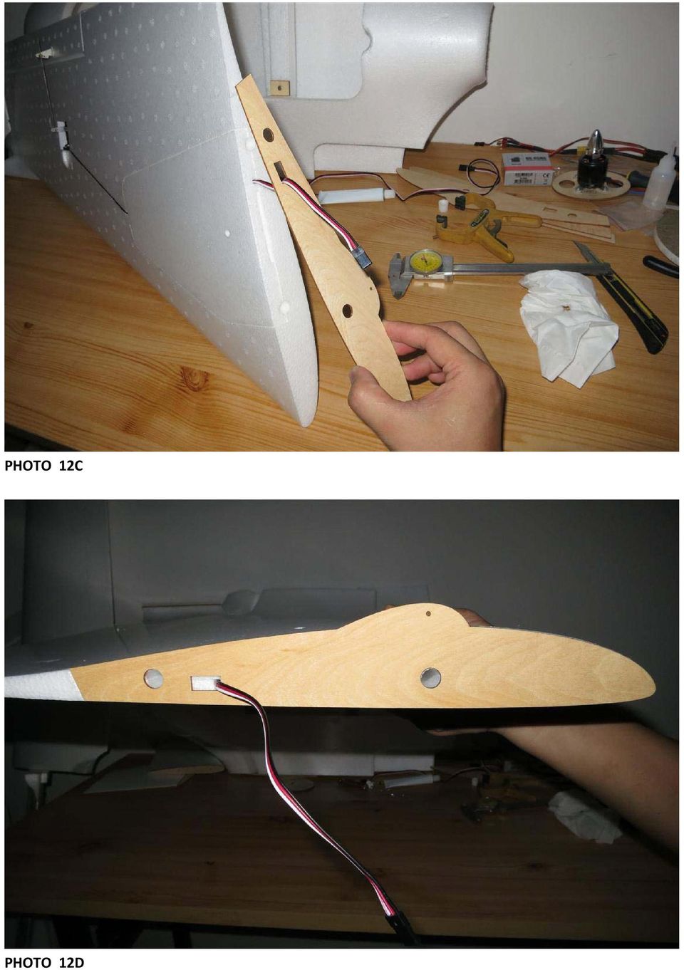
17 PHOTO 11C PHOTO 11D 12. Adding the Wing Butt Plate to the Main Wing Apply the supplied glue to the inner wing edge, make sure not to get any glue into the wing tube hole. Also apply glue to the butt plate, allow the glue to dry on both pieces for about 5 minutes. After the glue has dried insert the wing tube into it the wing tube cavity to help align the butt plate for the most accurate fit. Next insert the wing tube into the wing tube hole in the butt plate, and attach the butt plate to the wing.

18 See Photos 12A, 12B, 12C, and 12D. PHOTO 12A PHOTO 12B

19 PHOTO 12C PHOTO 12D
20 13. Running the Servo Extension into the Main Fuselage Body You will need to widen the slot in the fuselage so that the plug end of the servo lead will fit through the hole after the fuselage has been glued together. See Photos 13A and 13B. PHOTO 13A PHOTO 13B 14. Installing the Motor Mount into the Fuselage Optionally you can attach your motor to the motor mount before gluing it into the fuselage. If you do not attach your motor at this time you should have no problems mounting the motor after further construction. See Photos 14A, 14B, 14C, and 14D

21 PHOTO 14A PHOTO 14B.
22 PHOTO 14C PHOTO 14D
23 15. Gluing the Fuselage Halves Apply glue to the top and bottom sections of your fuselage. Wait approximately 5 minutes for the glue to dry. After the glue has dried press the two halves together forming a tight bond between the two halves together. Make sure to avoid the wing tube cut out area. See Photos 15A, 15B, 15C, and 15D. PHOTO 15A PHOTO 15B
24 PHOTO 15C PHOTO 15D 16. Installing the Wing Butt Plate onto the Fuselage Apply the supplied glue to the inner fuselage wing edge, make sure not to get any glue into the wing tube hole. Also apply glue to the butt plate, allow the glue to dry on both pieces for about 5 minutes. After the glue has dried insert the wing tube into it the fuselage wing tube cavity to help align the butt plate for the most accurate fit. Next attach the butt plate to the fuselage. See Photos 16A, 16B, and 16C.
25 PHOTO 16A PHOTO 16B
26 PHOTO 16C 17. Winglet Final Assembly Attach the winglet to the main wing with the two supplied 3x8 screws. If you plan on removing the winglets and re attaching prior to transport and flying you should add some foam safe CA to the winglet screw holes. By adding CA to the screw holes you are hardening the wood to accept the screws for multiple attachment and detachment of the winglet. See Photo 17A PHOTO 17A
27 18. Attaching the Motor If you did not pre attach the motor in step 15, you should attach the motor now. Follow the directions from the manufacturer of your motor to mount it. If your motor is not centered using the pre drilled holes in the motor mount, you should drill new holes to attach your motor, trying to keep the shaft as centered as possible in the center of the rear fuselage hole. See Photos 18A and 18B. PHOTO 18A PHOTO 18B
28 19. Recessed Camera Mount There are a multitude of fixed board cameras that will mount in the front of your Skywalker X8 without modification. There is also a pre formed hole in the fuselage to run your camera wires through. Also with the wide fuselage you have plenty of room to separate your video and audio transmitter from you radios receiver. If you are using a GOPRO camera for you FPV implementation you will need to make some modifications to the fuselage. First you will need to cut out a round hole to accommodate the GOPRO s round lens, also beveling the surface so that you are not obscuring the wide angle lens. See Photos 19A, 19B, and 19C. PHOTO 19A PHOTO 19B
29 PHOTO 19C 20. The Skywalker X8 Final Assembly Your final assembly should look almost identical to what you see in the photo. See Photos 20A, 20B, and 20C. PHOTO 20A
30 PHOTO 20B PHOTO 20C
31 21. Skywalker X8 Center of Gravity The center of gravity is marked by the rear most part of the cutouts for hand launching. This position is 440 millimeters away from the front of the fuselage. You may have to adjust the CG approximately either 5 millimeters forward or backwards from this starting point. See Photo 21A. PHOTO 21A 22. Assembly and Disassembly for Transportation Here the Skywalker X8 is shown partially disassembled for transportation or storage. See Photos 22A, 22B, 22C, 22D, and 22E. PHOTO 22A
32 PHOTO 22B PHOTO 22C
33 PHOTO 22D PHOTO 22E
34 23. Finished Skywalker X8 At this point the assembly of the Skywalker X8 should be complete. The last part of your assembly should be you radios receiver and you FPV equipment. See Photo 23A. PHOTO 23A
35 APPENDIX A READ THIS COMPLETELY BEFORE CONTINUING ON TO THIS CONFIGURATION CONVERTING STANDARD ELEVON TO DRAG RUDDER CONFIGURATION To convert the Skywalker X8 to a drag rudder configuration, you will need the following additional parts. Quantity Description 2 Control horns 2 Control rods 2 Pushrod connectors 2 Servos with a minimum of 2.5 Kg of force 2 Servo extensions 1. Measure the control surface, divide the control surface into two equal parts marking the location. 2. Cut the control surface into two equal parts, leaving about a 1.5 millimeter gap between the now two control surfaces so that they move independently of each other. 3. Find the place best suited for the mounting of the new servo. Cut or melt a hole into the wing, similar to the original servo hole in the wing that was provided by the manufacture. Make sure you have enough room for the servo arm to move correctly. 4. Create a channel for the servo wire extension to lay in. The servo wire channel should meet up with the original servo extension under the wing plate and, the new servo extension should exit under the wing plate at the same location on the butt end of the wing as the original servo extension wire. 5. After you have completed the above steps you can now continue through the rest of your build. At this point you should be at Step 7 or Step Your radio will have to have advanced configuration, or advanced programming ability to build your Skywalker X8 in this manner. 7. The basic idea of the drag rudder configuration is: When moving you aileron stick to the left (left turn) the outer control surface should move down while the inner control surface moves up the same distance from center. A right turn is the same. When moving the aileron stick to the right (right turn) the outer control surface should move down while the inner surface moves the opposite direction up.
TopSky DLG Installation Manual
 TopSky DLG Installation Manual Attention: Because after the compound materials solidify, there will be ammonia iris on the surface, which affect the bonding strength afterwards. Please polish with sandpaper
Assembly and Operating Manual Nano warbirds FW 190 Specification: *Length: 18 1/2"(470mm) *Wing Span: 21 7/10"(550mm)
 *Wing Span: 21 7/10(550mm)") Assembly and Operating Manual Nano warbirds FW 190 Specification: *Length: 18 1/2"(470mm) *Wing Span: 21 7/10"(550mm) *Flying Weight: 6 1/2 oz (185g) Dear customer, Congratulations on your choice of a
Assembly and Operating Manual Nano warbirds FW 190 Specification: *Length: 18 1/2"(470mm) *Wing Span: 21 7/10"(550mm) *Flying Weight: 6 1/2 oz (185g) Dear customer, Congratulations on your choice of a
Technical data. Assembly: Introduction. Before starting construction. Equipment needed. Glider or Electro Glider?
 Palio pro S2084 Technical data Wing span: Lenght: Weight: Wing area: Wing loading: El. Motor/ no. of cells: Controls: Introduction 2150 mm 1150 mm 1120 g 1860 g 42 dm2 27 g/dm2 44 g/dm2 600 / 7-8 cells
SebArt professional line
 SebArt professional line New Sukhoi 29S 50E ARF ASSEMBLY MANUAL The new Sukhoi 29S 50E ARF was designed by Italy aerobatic pilot, Sebastiano Silvestri and the design is based on of his new Tournament Of
How To Build A Roc Plane
 SebArt professional line AngelS EVO 50E ARF ASSEMBLY MANUAL The new AngelS EVO 50E ARF, was designed by the 10 times F3A Italian Champion Sebastiano Silvestri, it is the replica of his 2 meter size F3A
SebArt professional line AngelS 30E ARF
 SebArt professional line AngelS 30E ARF ASSEMBLY MANUAL The new AngelS 30E ARF, was designed by the 10 times F3A Italian Champion Sebastiano Silvestri, it is the replica of his 2 meter size F3A competition
PRODUCT MANUAL SPECIFICATIONS SAFETY PRECAUTIONS. 1460mm/57.48in 1112mm/43.78in 27.74dm²/429.96in² 1600g/56.50oz 57.68g/dm²
 SPECIFICATIONS SAFETY PRECAUTIONS PRODUCT MANUAL Wing span: Length: Wing area: Flying weight: Wing loading: 1460mm/57.48in 1112mm/43.78in 27.74dm²/429.96in² 1600g/56.50oz 57.68g/dm² This electric R/C model
BUILDING INSTRUCTION SAL-DLG MINI-FIREWORKS. MINI-Fireworks building instruction May 2015. www.pcm.at 1
 Wingspan [mm]: 950 Aspect ratio: 7,7 Wing area [dm2]: 11,7 Wing loading [g/dm²] : 12-13 Takeoff weight [g]: 155 (Mini-S), 165 (Mini-Q) Airfoil: AG03 mod 3-side-view version with ailerons BUILDING INSTRUCTION
Junkers Ju 88 Manual Version 1.2 13 March 2008
 Junkers Ju 88 Manual Version 1.2 13 March 2008 Specifications Wingspan: 49.75 inches Area: 339 square inches Length: 36.12 inches Power: 2x BP21 Brushless 2x Speed-400 Copyright 2007 Thomas A. Jacoby and
Katana EP. Specifications. 301 sq in / 19.4 sq dm. * Specifications are subject to change without notice.*
 INSTRUCTION MANUAL Katana EP Outrunner Motor Requires: -channel radio w/ micro servos, 0A Brushless ESC, 3 cells.v 00mAh Li-Po battery & charger. Wing Span Wing Area Flying Weight Fuselage Length HIGH
DL50 Discus Launch Glider
 DL50 Discus Launch Glider DL50 Specifications Length: 39 in. (99 cm.) Wingspan: 50in. (127 cm.) Wing Area: 275in 2 (1774 cm 2 ) Weight: 8oz. (227 g.) Revision History Date Revision Notes/Comments 6/12/2004
60 Sbach 342 Electric Aerobatic Aircraft
 60 Sbach 342 Electric Aerobatic Aircraft Specifications: Wing Span: 60 inches Length: 58 inches Power: Hacker A50-14S (or equivalent) Battery: 3800 5-cell LiPo ESC: 60-70 amp Flying Weight: 4.75-5.25 lbs
FREEBIRD THE ORIGINAL D.I.Y. ORNITHOPTER! Tools and Glue. Required Materials
 Do not try to make your ornithopter using "household materials". If you want it to fly, you have to build it right. FREEBIRD THE ORIGINAL D.I.Y. ORNITHOPTER! Wingspan: 16 inches Weight: 1/4 ounce The Ornithopter
Micro. Pitts Special for the RFFS-100 by Chris O Riley
 Micro Pitts Special for the RFFS-100 by Chris O Riley F1 F2 F3 F4 1 2 3 4 All wood 1/32 inch sheet unless otherwise stated. F1 F2 F3 F4 Small balsa blocks for LG reinforcement Small balsa blocks for LG
Brief introduction----------------------------------------------------------------------------03
 A-1 skyraider Brief introduction----------------------------------------------------------------------------03 Specification----------------------------------------------------------------------------------03
INSTRUCTION MANUAL. Black Angel. www.copterx.com. Features. Kit Helicopter. Copyright 2009 KY MODEL Company Limited.
 INSTRUCTION MANUAL Features - Carbon fiber main blade, tail blade, fly paddle, tail fin for extra weight saving and durability. - CNC machined high grade aluminum rotor head and tail gear box to ensure
Assembly Manual For. Dolphine Jet. Wingspan: 88 in Wingarea: 1479.8 sp in Length: 78.8 in Engine: 50CC. www.pilot-rc.com
 Assembly Manual For Dolphine Jet Wingspan: 88 in Wingarea: 1479.8 sp in Length: 78.8 in Engine: 50CC www.pilot-rc.com INTRODUCTION Thank you for purchasing our Dolphin Jet. we strive to achieve the real
RETRACTABLE LANDING GEAR
 HUGHES H-1 RETRACTABLE LANDING GEAR INSTALLATION INSTRUCTIONS Congratulations on your decision to add retractable landing gear to your RC model of the Hughes H-1. Though originally conceived simply for
BUILDING INSTRUCTION ERWIN XL slope ERWIN XL ultralight - ERWIN XL ultralight Elektro. Erwin XL building Instruction October 2012. www.pcm.
 Wing span [mm]: 3000 Aspect ratio: 14,67 Wing area [dm2]: 61,33 Wing loading: Erwin XL slope: 45,6-70,1 Erwin XL ultralight: 20,4 Erwin XL ultralight Elektro: 23,6-24,5 Weight [g]: Erwin XL slope: 2800-4300
Specifications. *Specifications are subject to change without notice.*
 INSTRUCTION MANUAL Extra 300 EP (0) 50W Motor System Requires : -channel radio w/ mini servos, Outrunner Motor KM37810, w/ Propeller Adaptor HW3010, 0A Brushless ESC with 11x8E proepller, cells 1.8V 300mAh
1/5 PIPER J-3 CUB. Before commencing assembly,please read these instructions thoroughly. Wing Span:84. 0 in / 2130 mm
 INSTRUCTION MANUAL Before commencing assembly,please read these instructions thoroughly. 1/5 PIPER J-3 CUB 1/5 PIPER J-3 CUB Wing Span:8. 0 in / 130 mm Wing Area:968 sq in / 6. 5 sq dm Flying Weight:8.
COMPLETE KIT PARTS LIST
 Your kit contains the following parts. Please check your kit for any missing or damaged parts before starting construction. Wood Bag: COMPLETE KIT PARTS LIST 1 LC-504-01 3/32"x4"x24" Laser Cut Balsa Sheet
harbor cub Electric Remote Control Airplane Model 92906 assembly & Operating Instructions
 harbor cub Electric Remote Control Airplane Model 92906 assembly & Operating Instructions IMPORTANT: If damage is caused due to a crash, your warranty is void. Visit our website at: http://www.harborfreight.com
Assembly Manual For. 30cc 88 Skywolf. www.pilot-rc.com. Note: some photos on the manual is not from Skywolf. But the installation way is the same.
 Assembly Manual For 30cc 88 Skywolf Wingspan: 88 in www.pilot-rc.com Wingarea: 1479.8 sp in Length: 78.8 in Engine: 50CC Note: some photos on the manual is not from Skywolf. But the installation way is
INSTRUCTION MANUAL. Specification: collective pitch 3D quadcopter. TYPE: Collective Pitch Electric 3D Quadcopter. Rotor Diameter: 118MM.
 collective pitch 3D quadcopter INSTRUCTION MANUAL Specification: TYPE: Collective Pitch Electric 3D Quadcopter Rotor Diameter: 118MM Length:635 MM Width: 365 MM Weight: 986g w/out battery Flying weight
Super Stunts 60. Specifications. * Specifications are subject to change without notice.*
 A L M O S T- R E A D Y- T O - F LY INSTRUCTION MANUAL Super Stunts 60 0.60-0.75 cu. in. displacement 2-stroke Requires : 4- channel radio w / Specifications 5 standard servos Wing Span Wing Area Flying
Have fun, nevertheless!
 Nanomum The Nanomum is a small pusher gyro for flying indoors or outdoors in very calm weather. It's got a dc head and is easy to build and easy to fly - I hope. Specs: AUW 70 g / 2.5 oz. Rotor diameter:
Introduction. Table of Contents. Specifications
 Assembly Manual Table of Contents Introduction...2 Table of Contents...2 Warning...3 Additional Required Equipment...3 Additional Tools and Adhesives...3 Contents of Kit/Parts Layout...4 Warranty Information...5
O P E R A T I N G I N S T R U C T I O N S
 O P E R A T I N G I N S T R U C T I O N S CAUTION The Phase 3 Models Fantom is designed for intermediate to advanced pilots. It's not intended for beginners. It is not a trainer! Specifications AND Features:
MS:158 ASSEMBLY MANUAL. Graphics and specifications may change without notice.
 MS:158 ASSEMBLY MANUAL Graphics and specifications may change without notice. Specifications: Wing span ------------------------------70.9in (180cm). Wing area -----------------644.8sq.in (41.6sq dm).
98 Turbine Vulcan Build photos
 98 Turbine Vulcan Build photos Just some of the useful tools needed plus a quality razor plane FUSELAGE Note: Fitting parts back to front is an easy mistake to make with this build, so mark all part with
T-28 Trojan Instruction Manual Charge-and-Fly Park Flyer
 T-28 Trojan Instruction Manual Charge-and-Fly Park Flyer Wingspan: 44 in (1118mm) Length: 36 in (914mm) Weight (RTF): 30 oz (875 g) Servos: Four 3-wire servos Motor: PKZ 480 960Kv outrunner brushless motor
Mini Edge 540 3D. Assembly Manual
 Mini Edge 540 3D Assembly Manual 2 Table of Contents Introduction...2 Specifications...2 Contents of Kit/Parts Layout...3 Required Electronics & Accessories...4 Recommended High Performance Motor Setup*...4
Park 250 Brushless Outrunner Instructions
 Park 250 Brushless Outrunner Instructions Thank you for purchasing the E-flite Park 250 Brushless Outrunner motor. This motor is ideal for 3D models 4-6 oz (115-170g), and sport and scale models 6-12 oz
Build Your Own Solar Car Teach build learn renewable Energy! Page 1 of 1
 Solar Car Teach build learn renewable Energy! Page 1 of 1 Background Not only is the sun a source of heat and light, it s a source of electricity too! Solar cells, also called photovoltaic cells, are used
You motor now is ready to run. Wires Connection: Installing the Controller: Normal start up:
 Dear customer, Thanks for purchase of our Brushless Motor Controller. This is a new generation of sensorless speed controllers, with latest humanize software design, especially for ALL types of brushless
SebArt professional line
 SebArt professional line Mini Avanti 1.4m ARF EDF or P20 micro-turbine ASSEMBLY MANUAL The all new Mini Avanti Jet 1.4m ARF was designed by Italy aerobatic pilot Sebastiano Silvestri. This sport ARF jet-model
Z-Truck (Vertical Moving) Z-truck Flag. Y-Truck (Horizontal Moving) FIGURE 1: VIEW OF THE Z-TRUCK. Flexshaft Assembly
 Z-truck Flag. Y-Truck (Horizontal Moving) FIGURE 1: VIEW OF THE Z-TRUCK. Flexshaft Assembly") Replacing the Cover Micro-Switch To remove and replace the Cover Micro-Switch you will need the following tools: #2 Phillips screwdriver (magnetic tip preferred) #1 Phillips screwdriver (magnetic tip preferred)
Replacing the Cover Micro-Switch To remove and replace the Cover Micro-Switch you will need the following tools: #2 Phillips screwdriver (magnetic tip preferred) #1 Phillips screwdriver (magnetic tip preferred)
ASSASSIN Building Instructions by CRASHTESTHOBBY.COM
 ASSASSIN Building Instructions by CRASHTESTHOBBY.COM The Assassin is the toughest plane on the planet!!! The Assassin can take more abuse and keep on flying better than any other plane we have seen. It
Phoenixtech Brushless Motor Speed Controller Programming Guide
 Congratulations on the purchase of your new Phoenixtech Brushless Motor Speed Controller. This latest series of controllers is unique in that it is equipped with a robust internal switching Battery Eliminator
Instruction Manual Specification:
 Instruction Manual Specification: Wingspan: 1855mm (73 ) Length: 1970mm (77.5 ) Weight: 7.5-9Kg (Approx.) Radio: 6+ Channel (Required) Turbine: 50-100N (5-10Kg) (Recommended) Introduction Congratulations
Modular Locomotive System Instruction Manual for HBK8 George Body Kit
 Modular Locomotive System Instruction Manual for HBK8 George Body Kit Roundhouse Engineering Co. Ltd. Units 6-10 Churchill Business Park. Churchill Road, Wheatley. Doncaster. DN1 2TF. England. Tel. 01302
Go-kart for little race-drivers
 Go-kart for little race-drivers Drill and drive. Go-kart What it lacks in speed, it more than makes up for in fun: the go-kart will excite little race-drivers. 1 Introduction It s only a go-kart, but it
Focke-Wulf Fw 190 INSTRUCTION MANUAL SAFETY PRECAUTIONS. Specification:
 Focke-Wulf Fw 90 Specification: Length :9 mm(57") Wing Span :00 mm(70.9") Wing Area :5. sq. dm.0 sq. ft Wing Loading :0. g/sq. dm.7 oz/sq. ft Flying Weight :5. kg(. lbs) Radio :ch& servos Engine :0 -cycle
A high performance model glider for slope soaring, designed by James D Hammond and brought to you by Sloperacer.
 Schwing 88 A high performance model glider for slope soaring, designed by James D Hammond and brought to you by Sloperacer. Thank you for purchasing the Schwing 88. The design remit was to extend the flight
Bill of Materials: Line Follower: A Zippy Robot That Senses Where to Go PART NO. 2170783
 Line Follower: A Zippy Robot That Senses Where to Go PART NO. 2170783 This kit has the parts you'll need with the exception of a few craft items sold separately to make a line-following cart. It uses a
INSTALLATION INSTRUCTIONS FOR G205 AND G207 STICK GRIPS
 1341 Distribution Way STe 15, Vista, A 92081 USA Ph 760.599.4720 Fx 760.599.4383 INSTALLATION INSTRUTIONS FOR G205 AND G207 STIK GRIPS G205 G207 Warning: Installation and use of Ray Allen ompany products
WE GET PEOPLE FLYING INSTRUCTION MANUAL
 TM WE GET PEOPLE FLYING INSTRUCTION MANUAL 90% prebuilt Great sport scale appearance Factory installed retracts Precovered in genuine UltraCote Prepainted fiberglass cowl Specifications Wingspan:... 65.5
INSTRUCTION MANUAL. 90% Pre-Built Build as Tail dragger or Tricycle Landing Gear System All Hardware Included
 90% Pre-Built Build as Tail dragger or Tricycle Landing Gear System All Hardware Included INSTRUCTION MANUAL Specifications for.40 Wingspan: 52-3/4" Length: 48" Wing Area: 593 sq. in. Weight (Approx):
Power Window/Power Lock Installation. To begin with you will need all the parts listed below:
 Power Window/Power Lock Installation To begin with you will need all the parts listed below: From Donor Fiero: Fiero power window regulators Power window motors (Generic GM type part) -motors are riveted
ADDING AN ELECTRIC AUXILIARY FAN TO RADIATOR STACK ON 03 ALPINE COACH
 ADDING AN ELECTRIC AUXILIARY FAN TO RADIATOR STACK ON 03 ALPINE COACH The original design of the 03 Alpine Coaches (and perhaps other years as well) did not include any kind of engine fan engage mechanism
Installation instructions, accessories - Handsfree for cellular phone, system B, entry level
 XC90 Section Group Weight(Kg/Pounds) Year Month 3 39 0.5/1.1 2006 07 XC90 2003, XC90 2004 IMG-249663 Page 1 of 18 Required tools A0000162 A0000163 IMG-239664 M0000232 IMG-253123 IMG-252223 Page 2 of 18
majestic install ation guide barcelona three sided enclosure 24mm surface mounted wall channels and underframe to base
 majestic install ation guide barcelona three sided enclosure 24mm surface mounted wall channels and underframe to base These Instructions are for a left and right handed unit. The diagrams show a left
Dave s Sheet Metal Bending Brake
 Dave s Sheet Metal Bending Brake I started building a Zenith CH601XL from plans in mid January 2006. After several failed attempts to bend the rudder spar I ended up going to a local sheet metal shop for
DYI INNOVA LIGHT BAR
 H U R D U S E W www.hurdusew.com PATRICK HURD: [email protected] Southwest Florida [email protected] www.hurdusew.com PARTS NEEDED All the parts were purchased at Home Depot Total Cost: 224.51 All parts
Build a Junior Solar Sprint Model Car Kit Materials: 1 PITSCO Ray Catcher Sprint Kit or Solar Made Junior Solar Sprint Kit 1 White Sheet of Plastic
 Build a Junior Solar Sprint Model Car Kit Materials: 1 PITSCO Ray Catcher Sprint Kit or Solar Made Junior Solar Sprint Kit 1 White Sheet of Plastic Coated Paper 2 Balsa Sheets (10-1/2 x4 x3/16 ) 2 Alligator
Building A Computer: A Beginners Guide
 Building A Computer: A Beginners Guide Mr. Marty Brandl The following was written to help an individual setup a Pentium 133 system using an ASUS P/I- P55T2P4 motherboard. The tutorial includes the installation
SILVER WINGS 1/32 GLOSTer gladiator Mk1/mk2 build guide
 SILVER WINGS 1/32 GLOSTer gladiator Mk1/mk2 build guide Parts Cleanup As with other Silver Wings kits, parts cleanup is fairly simple, and due to the soft resin they use for their kit, a sprue cutter can
Toledo Special 40 Assembly Manual
 Toledo Special 40 Assembly Manual Specifications Wingspan:... 69.5 in (1765.3mm) Length:... 50.8 in (1290.75mm) Wing Area:...702.8 sq in (45.3 sq dm) Weight:... 5.5 6.25 lb (2.49 2.83 kg) Radio:...4-channel
Service Guide. Gateway M275
 Service Guide Gateway M275 Contents Replacing Gateway M275 Components.................................... 1 Identifying the convertible tablet PC model...................................... 2 Identifying
Gripper Kit for the Boe-Bot Robot (#28202)
") 599 Menlo Drive, Suite 100 Rocklin, California 95765, USA Office: (916) 624-8333 Fax: (916) 624-8003 General: [email protected] Technical: [email protected] Web Site: www.parallax.com Educational: www.stampsinclass.com
599 Menlo Drive, Suite 100 Rocklin, California 95765, USA Office: (916) 624-8333 Fax: (916) 624-8003 General: [email protected] Technical: [email protected] Web Site: www.parallax.com Educational: www.stampsinclass.com
RC HELICOPTER INSTRUCTION MANUAL
 AGE 14+ RC HELICOPTER INSTRUCTION MANUAL 1. Smart R/C system 2. Full scale remote control 3. Omnidirectional flight 4. Smooth hover performance 5. Newly designed electricity saving functionality 6. Longer
Children s Furniture Projects
 This is an excerpt from the book Children s Furniture Projects by Jeff Miller Copyright 2002 by The Taunton Press www.taunton.com CHILD S ROCKER KIDS ARE ALWAYS IN MOTION. It s not easy to get them even
Build and Fly the Fokker D- 8
 Details are carefully carried out. Note movable controls The high wing gives it unusual stability Build and Fly the Fokker D- 8 Complete Data From Which You Can Build a Successful Model of a Famous German
BUILDINGA 1/10 SCALE FLATBED TRAILER
 VOLUME 1, ISSUE 1 BUILDINGA 1/10 SCALE FLATBED TRAILER BUILT, DESIGNED & WRITTEN BY NATHAN MYERS MATERIALS: FEATURES: While the design was kept simple to allow anyone to be able to build their own trailer,
SPRITE and BIGFOOT DESKTOP CNC MACHINE KIT ASSEMBLY INSTRUCTIONS
 SPRITE and BIGFOOT DESKTOP CNC MACHINE KIT ASSEMBLY INSTRUCTIONS README FIRST: Thank you for purchasing your MyDIYCNC Desktop CNC Machine Kit. We hope this versatile and innovative machine brings you many
Sundowner 36 ARF Assembly Manual
 Sundowner 36 ARF Assembly Manual Notice All instructions, warranties and other collateral documents are subject to change at the sole discretion of Horizon Hobby, Inc. For up-to-date product literature,
LG G5 Chassis Brace Gen 5 Camaro THE MOST POWERFUL HEADERS ON THE PLANET Brought to you by LG Motorsports 972-429-1963
 LG G5 Chassis Brace Gen 5 Camaro THE MOST POWERFUL HEADERS ON THE PLANET Brought to you by LG Motorsports 972-429-1963 Thank you for purchasing LG Motorsports products for your Gen 5 Camaro. Parts Inventory:
The JIG is UP Or A couple hours up front pays in the long run.
 Ed Simon Page 1 of 5 The JIG is UP Or A couple hours up front pays in the long run. A large part of the fun of beekeeping is the construction and assembly of the equipment. Since it is a hobby, I decided
DIRECTIONS FOR ASSEMBLING BASE & WALL CABINETS
 DIRECTIONS FOR ASSEMBLING BASE & WALL CABINETS TheRTAStore.com STEP 1: CLEAR A WORK SPACE Place your RTA cabinet panels on a smooth, scratch resistant surface in a large, open area. (Some people like to
Front landing gear legs. Carve from balsa block
 0 Carve these parts from balsa blocks C-1(2) C-2(3) Note: these cross pieces do not have formers attached. They help establish the proper curve of each fuselage side. Front landing gear legs Carve from
Lightening Holes. Plastics and Fiberglass. Engine Options. Retract Options. CAD Design. CAD Drawn Plans. Flaps. Cockpit Detail.
 messerschmitt ME109E The ME109 was the standard by which all other fighters of WWII were judged. It served the Luftwaffe in almost every capacity, from interceptor to night-fighter to ground attack and
Introduction to RC Airplanes. RC Airplane Types - Trainers, Sport RC Planes, 3D Acrobat RC Airplanes, Jets & More
 Introduction to RC Airplanes RC Airplane Types - Trainers, Sport RC Planes, 3D Acrobat RC Airplanes, Jets & More RC Airplane Types RC airplanes come in a few distinct categories. Each category generally
Assembly Manual For. Wingspan: 88 in Wingarea: 1479.8 sp in Length: 78.8 in Engine: 50CC
 Assembly Manual For 50cc aerobatic plane Wingspan: 88 in Wingarea: 1479.8 sp in Length: 78.8 in Engine: 50CC www.pilot-rc.com INTRODUCTION Thank you for purchasing our new 50cc aerobatic plane. we strive
SERVICE PARTS LIST PAGE 1 OF 6 BASE ASSEMBLY SPECIFY CATALOG NO. AND SERIAL NO. WHEN ORDERING PARTS 12" DUAL BEVEL COMPOUND MITER SAW B27A
 PAGE 1 OF 6 BASE ASSEMBLY 00 0 EXAMPLE: Component Parts (Small #) Are Included When Ordering The Assembly (Large #). SPECIFY CATALOG NO. AND NO. WHEN ORDERING PARTS 1 02-80-0050 Thrust Bearing (1) 2 05-80-0510
Assembly Manual For 100cc aerob 100cc aero a b ti t c pl p ane www. www pi p l i ot o --rc.com rc.com
 Assembly Manual For 100cc aerobatic plane www.pilot-rc.com INTRODUCTION Thank you for purchasing our new 100cc aerobatic plane. we strive to achieve a good quality quick build ARF aircraft. It requires
Modular Locomotive System Instruction Manual for HBK5 Billy Body Kit
 Modular Locomotive System Instruction Manual for HBK5 Billy Body Kit Roundhouse Engineering Co. Ltd. Units 6-10 Churchill Business Park. Churchill Road, Wheatley. Doncaster. DN1 2TF. England. Tel. 01302
PT-19 ARF. Assembly Manual. Specifications
 PT-19 ARF Assembly Manual Specifications Wingspan: 45 in (1440mm) Length: 36 in (910mm) Wing Area: 310 sq in (19.9 sq dm) Weight w/o Battery: 22 24 oz (680 740 g) Weight w/battery: 27 29 oz (820 880 g)
Stair Parts Installation. Tricks
 Stair Parts Installation Tips & Tricks Introduction Your DIY staircase guide Welcome to the Stairpart home installation guide. Your stairway is both a functional and focal point in your home, so keeping
Installation instructions, accessories. Cruise control. Volvo Car Corporation Gothenburg, Sweden. Instruction No Version Part. No. 30739998 1.
 Instruction No Version Part. No. 30739998 1.1 Cruise control Page 1 / 11 Equipment A0000162 A0000161 A0801178 D8802049 Page 2 / 11 M8802108 Page 3 / 11 IMG-223164 Page 4 / 11 IMG-213320 Page 5 / 11 INTRODUCTION
COOPER S PULLEY UPGRADE KIT INSTALLATION INSTRUCTIONS PART NUMBER NME5011
 COOPER S PULLEY UPGRADE KIT INSTALLATION INSTRUCTIONS PART NUMBER NME5011 Below are instructions for the Mini Mania Pulley Upgrade Kit, Part Number NME5011. Please take all necessary precautions for working
EZ-Steer Assisted Steering System
 EZ-Steer Assisted Steering System Installation Instructions Platform Kit P/N 53059-21 Case IH Puma 165 Puma 180 Puma 195 Puma 210 New Holland T7030 T7040 T7050 T7060 Revision A June 2007 Part Number 53345-21-EU2
Rebuild Instructions for 70001 and 70010 Transmission
 Rebuild Instructions for 70001 and 70010 Transmission Brinn, Incorporated 1615 Tech Drive Bay City, MI 48706 Telephone 989.686.8920 Fax 989.686.6520 www.brinninc.com Notice Read all instructions before
Manual LOGO 400 SE. www.mikado-heli.de
 Manual www.mikado-heli.de LOGO 400 SE Mikado Model Helicopters GmbH Friedrich-Klausing-Straße 2 14469 Potsdam Germany Phone +49 (0)331 23749-0 Fax +49 (0)331 23749-11 www.mikado-heli.de Mikado Model Helicopters
FRONT BUMPER INSTALLATION INSTRUCTIONS 2007-2011 DODGE / MERCEDES SPRINTER
 Aluminess Products Inc 9402 Wheatlands Ct. #A Santee, CA 92071 619-449-9930 FRONT BUMPER INSTALLATION INSTRUCTIONS 2007-2011 DODGE / MERCEDES SPRINTER Please read before beginning Stainless steel hardware
GENUINE PARTS INSTALLATION INSTRUCTIONS
 GENUINE PARTS INSTALLATION INSTRUCTIONS DESCRIPTION: Illuminated Kick Plate APPLICATION: Rogue (2011) PART NUMBER: 999G6 GX010 KIT CONTENTS: Item A B C G H QTY 1 1 1 D 1 E 1 F 3 15 6 Description Kick Plate,
The tablesaw may be your shop s most valuable cutting. Crosscut Sleds. Foolproof. Innovative approach guarantees perfect results
 Foolproof Crosscut Sleds Innovative approach guarantees perfect results B Y A L A N T U R N E R The tablesaw may be your shop s most valuable cutting tool, but for precise, repeatable crosscuts it needs
Chapter 3 Installing Over-the-Post Railing on an L-Shaped Stair
 49 Chapter 3 Installing Over-the-Post Railing on an L-Shaped Stair In this chapter: The Over-the-Post Balustrade System Determining the Rail Centerline Using Rail Bolts Making a Pitch Block Laying Out
Small form factor bay converter and hard drive installation
 Small form factor bay converter and hard drive installation HP xw6600 and HP xw8600 Workstations This document describes how to convert HP xw6600 and HP xw8600 Workstation 3.5-inch hard drive bays to hold
Dell P Series Monitor VESA Mounting Bracket Installation Instructions
 Dell P Series Monitor VESA Mounting Bracket Installation Instructions The VESA mounting bracket enables a Wyse cloud client to be mounted to the Dell P Series Monitor and the Dell E24 Monitor. The cloud
How to Build a Poker Table
 How to Build a Poker Table www.pokertablematerials.com 10-Person Poker Table- 96 x 48 These are step by step instructions for building a poker table. The table will measure 48" x 96" and have a 4" wide
ARH TIGER ASSEMBLY INSTRUCTIONS
 ARH TIGER ASSEMBLY INSTRUCTIONS Please use extreme caution in the building of the Defence paper models. Parental permission, help and supervision is required if being built by people under 18 years of
AstroSystems Digital Setting Circles for Zhumell, GSO, Apertura and Astro-Tech
 AstroSystems Digital Setting Circles for Zhumell, GSO, Apertura and Astro-Tech Components 1 Sky Commander Digital Setting Circle Computer 2 Encoders 10,000 step 1 Sky Commander Digital Setting Circle Manual
Overnight Sensations Speaker Kit
 Overnight Sensations Speaker Kit Thank you for purchasing the Overnight Sensation cabinet kit. This speaker kit was precision cut using CNC machinery for the best possible fit and finish. With a little
Installation Instructions Avalanche XUV Cap IMPORTANT! IMPORTANT!
 Installation Instructions Avalanche XUV Cap IMPORTANT! Read all instructions carefully before commencing any work. Always wear safety equipment. Some installation steps will require two or more installers.
Reasons for reissue are in Section 6, REVISION SUMMARY.
 Figure 1 This instruction sheet covers the application of OPTIMATE FSMA Fiber Optic Connector Types 905 and 906 for data and telecommunications applications. Base part numbers which apply to each type
Wren Kitchens Installation Tips... 3. Carefully check your kitchen delivery... 4. Measuring out and marking up... 5. Fitting the base cabinets...
 tra 1 Index Wren Kitchens Installation Tips... 3 Carefully check your kitchen delivery... 4 Measuring out and marking up... 5 Fitting the base cabinets... 6 Fitting the corner cabinets... 7 The 972mm or
POWER LOCK KIT GENERAL INSTALLATION -J04427 REV. 2007-12-04. Kit Number. Models. Additional Parts Required. Kit Contents
 -J0 REV. 00--0 POWER LOCK KIT GENERAL Kit Number -0, 0-0 Models For model fitment information, please see the P&A Retail Catalog or the Parts and Accessories section of www.harleydavidson.com (English
ROVs in a Bucket Building an Underwater Robot. 3.0 ROV Thrusters & Propeller Attachment. 3.1 Propulsion
 3.0 ROV Thrusters & Propeller Attachment 3.1 Propulsion ROV s move forward and back, up and down, and to the left and right. They can make all of these moves without the benefit of a rudder. With three