Note there are many options for how this model can be built, including:
|
|
|
- Jared Boyd
- 9 years ago
- Views:
Transcription
1 Page 1
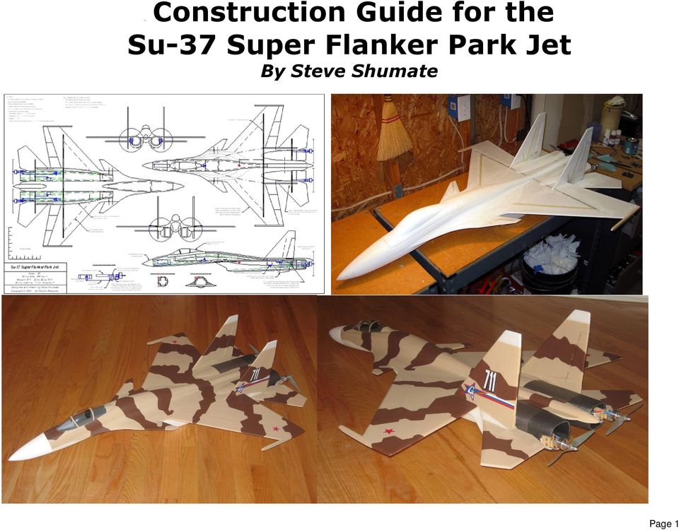
2 Introduction Welcome to the Su-37 park jet! This model was designed for twin Littlescreamers Park Jet (LSPJ) motors and features a working 3- axis thrust vectoring (TV) system, just like the real Su-37. With the TV system off, this model handles extremely well in the air and is very predictable, maneuverable, and easy to fly. But with the TV system on, it can do wingtip flips, incredibly tight turns, and wild tumbling maneuvers just like the real Su-37. The TV system also provides excellent controllability at ultra low airspeeds and high alpha. With the twin LSPJs, the top speed of this model is in the neighborhood of 80 mph and the thrust-to-weight ratio is between 1.4 and 1.7, providing unlimited vertical. Amazing performance for an electric model! The counter-rotating propellers also result in no prop torque, which provides very smooth launches and more jet-like handling qualities. The 3-axis thrust vectoring system provides roll, pitch, and yaw both motors gimbal up/down together for pitch, opposite for roll, and differential throttles provides yaw. The prototype model used separate servos for the tailerons and the thrust vectoring, for 4 servos total. This allows turning the TV system on and off at will (via a switch on the transmitter) and also allows easily adjusting the trims and rates of the TV system separately from the stabilators. However, this model was also designed so that the builder can eliminate the two stabilator servos and just slave the stabilators and TV together mechanically. This eliminates the cost and weight of the extra pair of servos and also greatly simplifies the transmitter programming. To do this, just run a pushrod from each servo to the stabilator control horn (note the control must be installed pointing down instead of up as shown on the plans), and then run a second pushrod from the control horn to the TV mechanism. Note this simplified TV setup will require a lot of manual adjustments in the linkages to ensure the stabilators and TV are properly aligned, especially once the airplane is trimmed. Note there are many options for how this model can be built, including: With or without canard The plans show all the modifications required to convert this Su-37 to one of the original non-canard Su-27 or Su-30 variants. All that's required is to delete the canard, modify the strake contours, and modify the vertical tail outline. The changes required to do this are shown in red on the plans. Twin motors or single motor This design can be easily adapted for a single centerline motor, which could be done with or without thrust vectoring (in this case it would be single-axis or pitch only). Note the upcoming Littlescreamers Super Park Jet Special motor would be an excellent match for a single-motor version. The changes required to do this are also shown on the plans. With or without thrust vectoring The TV system provides amazing maneuverability on this model but also adds quite a bit of weight, cost and complexity. For those that want a simpler version, this model can be built without the TV system and will still be a great-flying park jet. Another option is to go with the simplified TV system described above. Flight control options There are a wide range of flight control options on this model. To actuate everything (stabilators, flaperons, rudders, canard, thrust vectoring, throttles) would require 9 channels and up to 8 servos! But on the other hand, this model could also be flown just fine using tailerons and throttle only 3 channels and 2 servos. The setup used on the prototype model (and described in this manual) is in between these extremes, utilizing tailerons, rudder, thrust vectoring, and twin throttles, for 7 channels and 5 servos. Page 2

3 Building Tips This model can be built using the following types of adhesives: Epoxy (with or without microballons) Odorless cyanoacrylate (CA) with accelerator UHU Creativ for Styrofoam (or UHU POR) 3M 77 spray adhesive Hot glue gun ProBond (or Gorilla Glue) To minimize weight, try to use as little epoxy as possible on this model, saving it for only critical joints such as wing spars and motor mounts. You can also mix microballons into the epoxy to reduce weight considerably and help it fill gaps better. The majority of construction should use a lightweight and quick-drying adhesive such as foam-safe CA, UHU Creativ, or 3M 77. I personally use 3M 77 and UHU Creativ (pictured at left) for the majority of construction since they are strong, dry very quickly, and sand well. You ll notice that 3M Satin tape is called out several times in these instructions, since it works very well for hinges, leading edge protection, and general strengthening. When purchasing, make sure to get 3M Satin tape (sometimes called 3M Gift tape), which is sold in the purple container. The common 3M Scotch tape sold in a green container doesn t work nearly as well, nor does common packing tape. Begin construction by cutting out all of the paper parts templates with scissors, trimming them to within approximately 1/8 of the lines. Then test fit all of the templates onto the foam sheet, trying to minimize wasted foam as much as possible. Once you re satisfied with the arrangement, remove each template individually and spray the back of the template LIGHTLY with 3M 77 spray adhesive. Then replace the template onto the same spot on the foam sheet. Repeat for every template. After all the templates are tacked onto the foam, cut out all the pieces by cutting on the lines with a SHARP hobby knife. To help keep track of the parts, keep the paper templates on each piece until you re ready to use it. Page 3

4 1. Begin by assembling the thrust vectoring motor mounts. This step is optional you may choose to install straight motor sticks if you don t want to incorporate thrust vectoring. If so, just cut the hardwood motor mount to the length you need and skip the rest of this step. Cut the 3/8" square hardwood motor mount stick into two lengths a 3 3/8" main stick and a 1 1/2" movable portion. Drill a 1/8" dia. hole in the main stick to fit the 1/8" O.D. brass bearing tube (top photo), and then glue the tube in place with thin CA. Cut a small chamfer in the lower edge as shown. Then wrap the aft end of this stick with a layer of packing tape to ensure a smooth low friction surface. Sand the inside surface of the two 1/8 plywood side plates to make them as smooth as possible. Trim the aft edge of the movable motor mount stick as shown on the plans, and then glue on both side plates using epoxy or CA. After the glue is dry, drill the pivot hole through the top of both side plates at the same time, making sure it is exactly perpendicular to the plates (using a drill press is highly recommended). The assembled motor mount is shown in the middle photo. The movable portion pivots around a 3-48 bolt, and the system is actuated via a pushrod and Dubro micro ball link on the bottom. Make sure the system pivots smoothly, and sand or trim as required. For extra strength and security, install a small bolt and nut across the lower side plates and movable mount stick (bottom photo). Repeat for the second motor mount, making it a mirror-image of the first. IMPORTANT NOTE: It is important that the thrust line of the motor runs directly through the pivot pin. This will minimize strain on the thrust vectoring servo and also prevent pitch trim changes with throttle setting. The parts provided were designed specifically for the Littlescreamers Park Jet Special motor with the stock 3/8 stick mount. If you use a different motor and mount, you may need to make new custom side plates out of 1/8 plywood that raise or lower the movable motor mount stick to realign the thrust line with the pivot pin. If so, this won t be difficult since the design of these plates is very simple--just trim or extend the square upper edge as required. Page 4

5 2. Now begin assembly of the nacelle sides. Start by gluing the 3/4" square 1/16" plywood stabilizer bearing supports in place on each nacelle side using epoxy, at the location shown in the top picture at left. Note you'll need to cut a small notch in the top corner to clear the motor mount stick on the two outboard nacelle sides. Make sure to make mirror-image left and right side pieces (middle photo). Next carefully align the left and right sides of each nacelle and tape them together back to back (with the plywood squares on the outsides). Then drill a clearance hole for the stabilizer pivot rods through both support plates at the same time (bottom photo). Use a drill press if at all possible to ensure the hole is perfectly perpendicular. The stabilizer pivot rods should be able to turn freely in these holes, but with as little play as possible. Page 5
.")
6 3. Glue the nacelle side doublers to the inboard nacelle sides at the locations shown on the plans (top photo). 3M77 spray works very well for this. Note there are two layers of doublers, which will allow sanding these corners down to a very large radius once the model is assembled. Make sure to make left- and right-side pieces. Glue the nacelle side doublers to the outboard nacelle sides at the locations shown on the plans, using the same procedure as before (middle photo). Glue the main motor mount sticks in place on the outboard nacelle sides using epoxy. Make sure the chamfered edge is on bottom when installing. Optional: For less drag and a cleaner appearance, use a sharp hobby knife to cut a 45 angle on the inside edges of all the nacelle side doublers (bottom photo). Page 6

7 4. Test fit the movable section of the motor mounts and ensure they swing freely. Trim and sand if required. Install the thrust vectoring servos. A strong (40+ oz/in torque) metalgeared servo is required since a plastic-geared servo could get stripped if the prop hits the ground during landings. The prototype used a Hitec HS- 85MG servo, which worked very well. Use double-sided tape to attach the servo to the nacelle sides, and then glue in scraps of foam all around the servo to hold it securely and eliminate play. Lastly use thick CA and accelerator to glue the servo firmly in place. Cut the pushrods to length and install. Plug the servos into a receiver and test the thrust vectoring mechanisms to ensure they work properly. Set the throws up so that the motor mounts deflect about 30 degrees up and down. 5. Next build the wing. Lay the wing down over wax paper on a flat surface and use 30 minute epoxy to glue in the carbon tube wing spar. Mixing some microballons into the epoxy is recommended to reduce weight and help the glue fill gaps better (ProBond also works well). Place wax paper and some heavy books on top of the wing to hold it perfectly flat as the glue cures. After the glue has cured, sand the leading to a well-rounded shape and the trailing edge to a tapered shape. Apply a strip of 3M Satin tape around the entire leading edge for smoothness and improved durability. Page 7

8 6. Place the wing on a flat surface, and then glue the nacelle sides in place as shown, fitting the tabs in the nacelles to the pre-cut slots in the wing. Note the outboard nacelle sides are bent slightly inboard to form a gentle curve (though no heat-forming is required). Use four temporary 90 degree angle pieces of scrap foam to hold the nacelle sides perpendicular as the glue dries. Also note pins can be used to hold everything together while the glues dries. A gap-filling glue such as epoxy with microballons or ProBond is recommended for this step. Page 8

9 7. Next build and install the vertical tail and side rails. Begin by sanding the leading edge of the vertical tails to a well-rounded shape, and the trailing edge to a tapered shape. Apply a strip of 3M Satin tape to the leading edge for smoothness and durability Cut a slot in the vertical tail for the 1/32" plywood spar (note the location shown on the plans is different from the photo shown at left one of the lessons learned after building the prototype model!). Place the vertical tail over wax paper on a flat surface and the glue the aux spar in place using epoxy. Laminate the two fuselage side rails together using 3M77 (two pieces together for each side). Then glue the laminated side rails to the vertical tail piece as shown (top photo). Once the glue is dry, sand the side rails to a scale tapered and rounded shape (middle photo). See photos of the real Su-27/Su-37 for guidance on how these are shaped. Glue the completed vertical tail/side rail pieces to each side of the aft fuselage with epoxy (bottom photo). Use temporary 90 degree triangle scraps of foam on top of the wing (not shown here) to ensure the vertical tail is perpendicular to the wing. Note the rounded aft end of the side rails sits flush with the holes for the stabilator pivot rods. Page 9
. Then glue the laminated side rails to the vertical tail piece as shown (top photo).")
10 8. Now begin the forward fuselage assembly. Glue the forward fuselage doublers to the forward fuselage sides using 3M 77. Make sure to make left- and right-side pieces. Note that double thickness doublers are used throughout to allow sanding the forward fuselage to a very rounded shape after assembly. 9. Using a heat gun, gently heat and bend the forward fuselage sides to the shape shown in the photo at left and on the plans. For guidance in shaping this piece, use the turtledeck top piece to trace an outline on the top of the wing with a Sharpie marker (shown in the photo at left). Then simply bend the fuselage sides to match that outline. Drawing a centerline on the wing will also help keep the fuselage properly aligned. Page 10
.")
11 10. Next install the forward fuselage onto the wing, including the sides and four bulkheads (you can install all of these parts at once). Use epoxy with microballons (or ProBond) and use pins and masking tape to keep everything aligned and in place. Glue the forward fuselage sides to the TOP of the wing first, then let the glue dry. 11. Now glue the forward fuselage sides to the bottom of the wing. It will help to draw an outline on the bottom of the wing first (simply trace the forward fuselage bottom piece) to provide guidance on how much to bend these parts in. Page 11

12 12. Glue on the forward fuselage top and turtledeck tops (top photo). I found it easier to NOT laminate the turtledeck tops before installing just glue the first one, let the glue dry, and then glue the second one on top of the first). Glue on the forward fuselage bottom piece (bottom photo). 13. Laminate the nosecone pieces together using 3M 77 adhesive. Then glue the nosecone block to the front of the fuselage. Once the glue has dried, sand the nosecone to shape. Start by tracing the top outline of the nosecone onto the foam (using the provided template) and cut it to shape with a long knife or saw. Begin with coarse sandpaper (100 grit) to rough out the basic shape, then move to a finer sandpaper (220 grit) to do the final shaping. End with 320 grit sandpaper to do the final polish sanding and provide a very smooth surface. Page 12
 and cut it to shape with a long knife or saw.")
13 14. Laminate all of the canopy pieces together using 3M 77 adhesive. Note how the two sill pieces are attached to the outside edges of the block. Once the glue has dried, sand the canopy to shape. Start by tracing the top outline of the canopy onto the foam (using the provided template) and use that to guide the shaping. Begin with coarse sandpaper (100 grit) to rough out the basic shape, then move to a finer sandpaper (220 grit) to do the final shaping. End with 320 grit sandpaper to do the final polish sanding and provide a very smooth surface. Note that custom-molded clear canopies are also available from Page 13
 to rough out the basic shape, then move to a finer sandpaper (220 grit) to do the final shaping.")
14 15. Next make and install the wing fillets. Begin by laminating the three fillet pieces together using 3M77. Then rough sand the fillets to a smooth concave shape using a rounded sander (I simply wrapped sandpaper around an epoxy bottle as shown in the middle photo). Start with coarse sandpaper and work your way to finer grits. Once the fillets are roughed to shape, glue them to the wing/fuselage. Then apply generous amounts of lightweight spackling compound all around the fillets and sand to a smooth well-blended shape. See photos of the real Su-27/Su-37 for guidance in shaping these. It takes quite a bit of time to properly shape these fillets, but take your time to do it right they are a very integral and recognizable feature of the Su-27/Su-37 airplanes! Page 14

15 16. Next make and install the canards. Bare foam canards will not be strong enough and must be strengthened. There are several ways this could be done, including installing hard balsa around all edges of the canard, fiberglassing the entire canard, or installing 1/32" plywood spars and covering with Satin tape (as shown in the top photo). Chose the method you prefer. Begin by sanding the canard pieces to a symmetrical airfoil shape. Then add the strengthening using your selected method. Next cut slots in the canards for the plywood dihedral braces and then glue them in place with epoxy as shown. Cut matching slots in the wing for the plywood dihedral braces and then glue the completed canards in place with epoxy as shown. Page 15

16 17. Next install the stabilators. Sand the leading edge of the stabilators to a well-rounded shape, and the trailing edge to a tapered shape. Apply a strip of 3M Satin tape to the leading edge for smoothness and durability. Lay the stabilators over wax paper on a flat surface and glue the carbon tube pivots into place using epoxy (top photo). Note the hardware required for the stabilators (second photo from top). The carbon tubes pivot inside the plywood supports in the nacelle sides. Two plywood end stops butt up against each support to keep the pivot tube from sliding left/right. A plywood control arm is installed to allow a pushrod connection to the servo. Putting a small piece of packing tape over the plywood supports in the nacelles to minimize friction with the end stop bearings is recommended. Slide the carbon pivot tube through the outboard ply support, and then slide on an end stop, control horn, and the other end stop (third photo from top). Push the pivot rod through to the inboard ply support. Once everything is in place and aligned, glue the end stops into place with epoxy or thick CA, but don t glue the control horn yet. Install the stabilator servos using a similar procedure as the thrust vectoring servos (double-sided tape, foam block supports, thick CA reinforcement). Then install the pushrods. Once everything is aligned properly, glue the plywood control horn to the carbon tube using epoxy or CA. Repeat for the other stabilator. Page 16

17 18. Next install the inlet diverter pieces. Glue the 3mm Depron triangular inlet diverter center pieces to the 3mm Depron inlet diverter top pieces (top photo). Make sure to make left and right hand pieces. Glue the above assembly into place at the front of the inlets (bottom two photos). Then glue the 6mm Depron internal inlet top piece in place directly behind the diverter pieces. Page 17
.")
18 19. Laminate the aft fuselage top and bottom spine pieces using 3M 77. Then sand to a well rounded shape, and taper the back end to a spike (top photo). Sand the decorative nacelle top pieces to a rounded shape with feathered edges (top photo). Glue the top spine, bottom spine, and nacelle tops to the aft fuselage (middle and bottom photos). Page 18
.")
19 20. Install the receiver, speed controls, and wiring. There are many ways you could do this, but I chose to install the receiver in the forward left nacelle (top photo), and one speed control in each nacelle flush with the inboard nacelle sides (bottom photo). Try to locate everything as far forward as possible since this model tends to be tail-heavy. Twist all the ESC wires together to help reduce electromagnetic interference, and tape all wiring down flat against the foam to keep them from flopping around in flight. To connect the components on opposite sides of the airplane, I simply ran the wiring across the bottom of the wing and then taped them down flat to the wing. Although these wires will be visible externally, you can paint over them later to help hide them. Note the battery extension wires must branch off in a Y to connect to each speed control. Use 16 ga minimum for the battery to ESC extensions, and you can use either 16 ga or 18 ga for the ESC to motor extensions. Make sure all of the electronics work properly before proceeding to the next step, since once the nacelle bottoms are glued on you'll have to cut into the model to gain access. NOTE: Make sure to install the speed controls so that they get PLENTY of airflow for cooling. Mounting them inside the nacelles as shown is ideal. I even cut away some of the plastic shrink wrap to promote even better cooling. Cooling is important not just because of the heat generated by the motor controller, but even more so for the integrated BEC circuitry since this model requires 4 servos (and most speed controls are only rated for 3 or 4 servos). Providing ample cooling to the BEC will allow it operate the servos safely and help prevent premature shutdowns due to overheating. Note you could use a separate and more powerful BEC component instead, but that would add weight and cost. Page 19

20 21. Sand the bottom of the nacelles flush with a long sander. Then glue on the nacelle bottoms. Sand the nacelle lower edges to a well-rounded shape. Page 20

21 22. Sand the balsa wing tip missile rails to shape and glue to the wing tips. 23. If incorporating rudders, install the rudder control hardware now. Rudders are not required and this model flies fine without them, but they are helpful for improved control at high alpha and for better aerobatics. Mount the servo in a slot in the wing on the centerline under the canopy. Use Sullivan micro flexible cable pushrods, with small pieces of 1/32 music wire soldered onto the rudder end. Make a small hole in the fuselage sides for the pushrod to exit, and then cut a slit in the top of the wing as shown and push the pushrod down into that slit. Then glue the pushrod in using thin CA and accelerator. Filler can be added before painting to help hide these pushrods. I used Dubro micro pushrod keepers on the rudder horn and Dubro micro EZ connectors on the servo end. Use a 90 degree servo arm and make sure the pushrods connect to the servo arm at a 90 degree angle at neutral (to ensure the rudders deflect equally). Page 21
22 24. Optional step If you plan to fly this model aggressively (either high speed, high weight, or aggressive aerobatics or tumbling), it is highly recommend to install a 1/32" plywood auxiliary spar in each wing as shown on the plans and in the photo at left. This spar will significantly strengthen the front of the wing and prevent it from flexing. Just cut a slot with a sharp knife into the wing and then glue the spar in with epoxy. It is also highly recommended that the stabilators be strengthened chordwise. Just run a 1" wide strip of fiberglass cloth chordwise at the root from front to back and on top and bottom, and adhere the cloth with either water-based polyurethane or epoxy. 25. CONGRATULATIONS! Your model is now complete. The model can be flown as is or can be painted using a variety of paints (see the next step for painting advice). I actually recommend test flying the airplane before painting it to allow making the maiden flight at the lowest possible weight and to allow you to more easily fix any internal problems that might arise. Page 22
23 PAINTING TIPS - This model can be painted with a wide variety of paints, just make sure to test compatibility with the foam first. The prototype was painted with standard acrylic craft paint (available at most craft stores), which can be applied with either a brush or airbrush. Here are a few painting tips: Wipe the entire model with rubbing alcohol before painting to remove all grease and dirt. Rough areas should be filled with lightweight wall spackling compound thinned with water, which fills the holes and can be sanded to a very smooth finish with minimal weight gain. Primer isn t required over Depron, but applying a coat of water-based polyurethane (WBPU) will help seal the foam and provide a smoother finish. Mixing some microballons or baby powder in with the WBPU will help fill holes even better and improves the finish further. When thinning acrylic paint for use in an airbrush, thin roughly 50/50 with windshield wiper fluid. The wiper fluid will allow the paint to dry faster (relative to thinning with water), which reduces the chance of runs. It will not affect the finish. Decals can be made on a computer and printed onto standard label paper using an inkjet or color laser printer. Good luck, and I hope you enjoy this model as much as I have! Page 23
24 Additional Photos For Reference Page 24
25 Flight Setup 1. Below is a chart that summarizes all of the channel assignments and mixes used on the prototype model (utilizing a Futaba 9C transmitter). Note that if you don't have a programmable or 7 channel transmitter, you can just build the mechanically slaved TV version. That eliminates the need for all of the custom mixes and 2 additional channels. 2. Adjust the flight controls to provide the following recommended deflections (all measured at the root trailing edge): Stabilators (pitch): +/- 1.5" (-30% expo) Stabilators (roll): +/- 1.5" (-30% expo) Rudder: +/- 0.75" Thrust vectoring: +/- 30 degrees (mixed with elevator) 3. Start with the CG at 6.1 ahead of the centerline of the carbon tube wing spar (see the plans). Depending on how your model is set up, some ballast may be required in the nose to achieve this CG (the prototype required 1.25 oz ballast on the final painted model). This is a relatively conservative forward CG location, great for making first flights. You can move the CG aft for more Page 25
26 maneuverability later as desired. 4. To hand launch this model, grip the airplane on one of the nacelles just behind the CG, apply about 75% throttle, and throw it overhand moderately hard, straight ahead, and slightly nose up. Make sure to keep your hand away from the prop as you throw it! With twin LSPJ motors this model has a lot of power, and full throttle launches aren't required (plus launching at a somewhat lower power setting will give you more time to react after you've released the model). 5. You ll find this model is surprisingly docile and predictable in the air and has no bad habits. But with the TV on it is capable of amazing aerobatics! 6. Belly landings are easy to do with this model, but remember to ALWAYS release the elevator control right before touchdown to prevent the forward stabilator tips from digging into to the grass or ground which can significantly damage the model and/or stabilator servo! Also remember to pull the throttle back to zero just before touchdown so that the propeller and/or motor mount is not damaged on landing. 7. For much more information about this model, check out the online discussion thread on RCGroups at the link below: Page 26
27 Specifications Wing area: 290 sq in Span: 30.0 Length: 36.3 Weight RTF: 22 to 29 oz Wing loading: 11 to 14 oz/sq ft Flight controls: Tailerons, rudder (optional), thrust vectoring (optional) Recommended equipment: Motor: Two Littlescreamers Park Jet (LSPJ) Battery: One Thunder Power 2100 mah 11.1V Prolite Prop: APC 6x4 regular and pusher (counter-rotating props) Speed control: Two Castle Creations Thunderbird 18 or Phoenix 25 Receiver: Castle Creations Berg 7P Servos: Futaba S3110 on all flight controls, Hitec HS-85MG on thrust vectoring Page 27
Technical data. Assembly: Introduction. Before starting construction. Equipment needed. Glider or Electro Glider?
 Palio pro S2084 Technical data Wing span: Lenght: Weight: Wing area: Wing loading: El. Motor/ no. of cells: Controls: Introduction 2150 mm 1150 mm 1120 g 1860 g 42 dm2 27 g/dm2 44 g/dm2 600 / 7-8 cells
TopSky DLG Installation Manual
 TopSky DLG Installation Manual Attention: Because after the compound materials solidify, there will be ammonia iris on the surface, which affect the bonding strength afterwards. Please polish with sandpaper
COMPLETE KIT PARTS LIST
 Your kit contains the following parts. Please check your kit for any missing or damaged parts before starting construction. Wood Bag: COMPLETE KIT PARTS LIST 1 LC-504-01 3/32"x4"x24" Laser Cut Balsa Sheet
Have fun, nevertheless!
 Nanomum The Nanomum is a small pusher gyro for flying indoors or outdoors in very calm weather. It's got a dc head and is easy to build and easy to fly - I hope. Specs: AUW 70 g / 2.5 oz. Rotor diameter:
SebArt professional line
 SebArt professional line New Sukhoi 29S 50E ARF ASSEMBLY MANUAL The new Sukhoi 29S 50E ARF was designed by Italy aerobatic pilot, Sebastiano Silvestri and the design is based on of his new Tournament Of
How To Build A Roc Plane
 SebArt professional line AngelS EVO 50E ARF ASSEMBLY MANUAL The new AngelS EVO 50E ARF, was designed by the 10 times F3A Italian Champion Sebastiano Silvestri, it is the replica of his 2 meter size F3A
Junkers Ju 88 Manual Version 1.2 13 March 2008
 Junkers Ju 88 Manual Version 1.2 13 March 2008 Specifications Wingspan: 49.75 inches Area: 339 square inches Length: 36.12 inches Power: 2x BP21 Brushless 2x Speed-400 Copyright 2007 Thomas A. Jacoby and
DL50 Discus Launch Glider
 DL50 Discus Launch Glider DL50 Specifications Length: 39 in. (99 cm.) Wingspan: 50in. (127 cm.) Wing Area: 275in 2 (1774 cm 2 ) Weight: 8oz. (227 g.) Revision History Date Revision Notes/Comments 6/12/2004
FREEBIRD THE ORIGINAL D.I.Y. ORNITHOPTER! Tools and Glue. Required Materials
 Do not try to make your ornithopter using "household materials". If you want it to fly, you have to build it right. FREEBIRD THE ORIGINAL D.I.Y. ORNITHOPTER! Wingspan: 16 inches Weight: 1/4 ounce The Ornithopter
SebArt professional line AngelS 30E ARF
 SebArt professional line AngelS 30E ARF ASSEMBLY MANUAL The new AngelS 30E ARF, was designed by the 10 times F3A Italian Champion Sebastiano Silvestri, it is the replica of his 2 meter size F3A competition
Build and Fly the Fokker D- 8
 Details are carefully carried out. Note movable controls The high wing gives it unusual stability Build and Fly the Fokker D- 8 Complete Data From Which You Can Build a Successful Model of a Famous German
98 Turbine Vulcan Build photos
 98 Turbine Vulcan Build photos Just some of the useful tools needed plus a quality razor plane FUSELAGE Note: Fitting parts back to front is an easy mistake to make with this build, so mark all part with
Micro. Pitts Special for the RFFS-100 by Chris O Riley
 Micro Pitts Special for the RFFS-100 by Chris O Riley F1 F2 F3 F4 1 2 3 4 All wood 1/32 inch sheet unless otherwise stated. F1 F2 F3 F4 Small balsa blocks for LG reinforcement Small balsa blocks for LG
BUILDING INSTRUCTION SAL-DLG MINI-FIREWORKS. MINI-Fireworks building instruction May 2015. www.pcm.at 1
 Wingspan [mm]: 950 Aspect ratio: 7,7 Wing area [dm2]: 11,7 Wing loading [g/dm²] : 12-13 Takeoff weight [g]: 155 (Mini-S), 165 (Mini-Q) Airfoil: AG03 mod 3-side-view version with ailerons BUILDING INSTRUCTION
MS:158 ASSEMBLY MANUAL. Graphics and specifications may change without notice.
 MS:158 ASSEMBLY MANUAL Graphics and specifications may change without notice. Specifications: Wing span ------------------------------70.9in (180cm). Wing area -----------------644.8sq.in (41.6sq dm).
How to Build a Poker Table
 How to Build a Poker Table www.pokertablematerials.com 10-Person Poker Table- 96 x 48 These are step by step instructions for building a poker table. The table will measure 48" x 96" and have a 4" wide
O P E R A T I N G I N S T R U C T I O N S
 O P E R A T I N G I N S T R U C T I O N S CAUTION The Phase 3 Models Fantom is designed for intermediate to advanced pilots. It's not intended for beginners. It is not a trainer! Specifications AND Features:
Installing Window and Door Mouldings
 Installing Window and Door Mouldings About Window and Door Mouldings The trim around windows and doors greatly influences the look and style of your interior. They also bridge the gaps and cover spaces
Introduction. Table of Contents. Specifications
 Assembly Manual Table of Contents Introduction...2 Table of Contents...2 Warning...3 Additional Required Equipment...3 Additional Tools and Adhesives...3 Contents of Kit/Parts Layout...4 Warranty Information...5
INSTRUCTION MANUAL. Black Angel. www.copterx.com. Features. Kit Helicopter. Copyright 2009 KY MODEL Company Limited.
 INSTRUCTION MANUAL Features - Carbon fiber main blade, tail blade, fly paddle, tail fin for extra weight saving and durability. - CNC machined high grade aluminum rotor head and tail gear box to ensure
Skywalker X8. Assembly manual January 2013
 Skywalker X8 Assembly manual January 2013 This Manual Was Created by Ray Grauberger www.raygrauberger.com Technical Data This is the X-8 FPV wing from Skywalker Technology. The BIG FPV wing! The X-8 has
1/5 PIPER J-3 CUB. Before commencing assembly,please read these instructions thoroughly. Wing Span:84. 0 in / 2130 mm
 INSTRUCTION MANUAL Before commencing assembly,please read these instructions thoroughly. 1/5 PIPER J-3 CUB 1/5 PIPER J-3 CUB Wing Span:8. 0 in / 130 mm Wing Area:968 sq in / 6. 5 sq dm Flying Weight:8.
Assembly and Operating Manual Nano warbirds FW 190 Specification: *Length: 18 1/2"(470mm) *Wing Span: 21 7/10"(550mm)
 *Wing Span: 21 7/10(550mm)") Assembly and Operating Manual Nano warbirds FW 190 Specification: *Length: 18 1/2"(470mm) *Wing Span: 21 7/10"(550mm) *Flying Weight: 6 1/2 oz (185g) Dear customer, Congratulations on your choice of a
Assembly and Operating Manual Nano warbirds FW 190 Specification: *Length: 18 1/2"(470mm) *Wing Span: 21 7/10"(550mm) *Flying Weight: 6 1/2 oz (185g) Dear customer, Congratulations on your choice of a
BUILDINGA 1/10 SCALE FLATBED TRAILER
 VOLUME 1, ISSUE 1 BUILDINGA 1/10 SCALE FLATBED TRAILER BUILT, DESIGNED & WRITTEN BY NATHAN MYERS MATERIALS: FEATURES: While the design was kept simple to allow anyone to be able to build their own trailer,
Panel/Hand Saw Kit Assembly Instructions
 Panel/Hand Saw Kit Assembly Instructions PLEASE READ THE FOLLOWING INSTRUCTIONS BEFORE BEGINNING Brief Summary You will be performing the following Tasks: 1. Determining the degree of shaping laying out
BUILDING INSTRUCTION ERWIN XL slope ERWIN XL ultralight - ERWIN XL ultralight Elektro. Erwin XL building Instruction October 2012. www.pcm.
 Wing span [mm]: 3000 Aspect ratio: 14,67 Wing area [dm2]: 61,33 Wing loading: Erwin XL slope: 45,6-70,1 Erwin XL ultralight: 20,4 Erwin XL ultralight Elektro: 23,6-24,5 Weight [g]: Erwin XL slope: 2800-4300
WE GET PEOPLE FLYING INSTRUCTION MANUAL
 TM WE GET PEOPLE FLYING INSTRUCTION MANUAL 90% prebuilt Great sport scale appearance Factory installed retracts Precovered in genuine UltraCote Prepainted fiberglass cowl Specifications Wingspan:... 65.5
Assembly Manual For. 30cc 88 Skywolf. www.pilot-rc.com. Note: some photos on the manual is not from Skywolf. But the installation way is the same.
 Assembly Manual For 30cc 88 Skywolf Wingspan: 88 in www.pilot-rc.com Wingarea: 1479.8 sp in Length: 78.8 in Engine: 50CC Note: some photos on the manual is not from Skywolf. But the installation way is
How To Build A Plane From Scratch
 BUILDING INSTRUCTIONS FOR THE SOLANGE (SUN ANGEL) The Solange has had a very long period in which to develop. It was originally designed for flying from the Bwlch in South Wales during 1993 as a glider
Super Stunts 60. Specifications. * Specifications are subject to change without notice.*
 A L M O S T- R E A D Y- T O - F LY INSTRUCTION MANUAL Super Stunts 60 0.60-0.75 cu. in. displacement 2-stroke Requires : 4- channel radio w / Specifications 5 standard servos Wing Span Wing Area Flying
Mini Edge 540 3D. Assembly Manual
 Mini Edge 540 3D Assembly Manual 2 Table of Contents Introduction...2 Specifications...2 Contents of Kit/Parts Layout...3 Required Electronics & Accessories...4 Recommended High Performance Motor Setup*...4
INSTRUCTION MANUAL. 90% Pre-Built Build as Tail dragger or Tricycle Landing Gear System All Hardware Included
 90% Pre-Built Build as Tail dragger or Tricycle Landing Gear System All Hardware Included INSTRUCTION MANUAL Specifications for.40 Wingspan: 52-3/4" Length: 48" Wing Area: 593 sq. in. Weight (Approx):
Front landing gear legs. Carve from balsa block
 0 Carve these parts from balsa blocks C-1(2) C-2(3) Note: these cross pieces do not have formers attached. They help establish the proper curve of each fuselage side. Front landing gear legs Carve from
How to Build Your Own CornHole Game
 How to Build Your Own CornHole Game DIMENSIONS Here is a diagram with the basic measurements for the Cornhole board game. SUPPLIES 1/2 thick sheet of plywood one 4 x4 or two 2 x4 s 8 long 2 4 s (4) 4 1/2
Juice Box Stages 1&2 135&335 Installation Guide 5/10/08
 Tools Required: 8mm socket or nut driver Small flat head screwdriver Electrical tape, masking tape, or shrink tube Pep talk: Although the install looks daunting at first, once you get the learning curve
2. This is a close up of a typical area where the rocker is rusted out leaving holes under where the rocker moulding would be..
 ROCKER PANELS 55,56,57 CHEVY REPLACEMENT Do not throw away any pieces when you first remove them. There are many supports that are not reproduced and will need to be used again. When disassembling try
Specifications. *Specifications are subject to change without notice.*
 INSTRUCTION MANUAL Extra 300 EP (0) 50W Motor System Requires : -channel radio w/ mini servos, Outrunner Motor KM37810, w/ Propeller Adaptor HW3010, 0A Brushless ESC with 11x8E proepller, cells 1.8V 300mAh
STEADYfast Stabilizer Installation Notes Fifth Wheel and Travel Trailers 11/23/13
 STEADYfast Stabilizer Installation Notes Fifth Wheel and Travel Trailers 11/23/13 (See Supplemental Instructions for trailers with heavy duty round footplates and/or Power Leveling Systems) PHONE SUPPORT
Instruction Manual Specification:
 Instruction Manual Specification: Wingspan: 1855mm (73 ) Length: 1970mm (77.5 ) Weight: 7.5-9Kg (Approx.) Radio: 6+ Channel (Required) Turbine: 50-100N (5-10Kg) (Recommended) Introduction Congratulations
SebArt professional line
 SebArt professional line Mini Avanti 1.4m ARF EDF or P20 micro-turbine ASSEMBLY MANUAL The all new Mini Avanti Jet 1.4m ARF was designed by Italy aerobatic pilot Sebastiano Silvestri. This sport ARF jet-model
Katana EP. Specifications. 301 sq in / 19.4 sq dm. * Specifications are subject to change without notice.*
 INSTRUCTION MANUAL Katana EP Outrunner Motor Requires: -channel radio w/ micro servos, 0A Brushless ESC, 3 cells.v 00mAh Li-Po battery & charger. Wing Span Wing Area Flying Weight Fuselage Length HIGH
Build Your Own Solar Car Teach build learn renewable Energy! Page 1 of 1
 Solar Car Teach build learn renewable Energy! Page 1 of 1 Background Not only is the sun a source of heat and light, it s a source of electricity too! Solar cells, also called photovoltaic cells, are used
Rudder Repair and refinish
 Rudder Repair and refinish Montgomery 23 Dauntless The before photograph A receipt found inside the boat showed a previous owner had enlisted a boat yard to perform maintenance on the rudder by shortening
www.cornholesupplies.com
 www.cornholesupplies.com How To Build Regulation Cornhole Boards Home of the Original Cornhole Bags and Boards Supply List: 1-4' X 8' Piece of Plywood (pre sanded) 4-2" X 4" X 8' Studs (2 by 4s make sure
60 Sbach 342 Electric Aerobatic Aircraft
 60 Sbach 342 Electric Aerobatic Aircraft Specifications: Wing Span: 60 inches Length: 58 inches Power: Hacker A50-14S (or equivalent) Battery: 3800 5-cell LiPo ESC: 60-70 amp Flying Weight: 4.75-5.25 lbs
MGB Chrome Bumper Conversion
 MGB Chrome Bumper Conversion Installation Instructions For 1974 1/2-1980 MGB This kit requires cutting, welding, and painting. Professional installation recommended. Note: Every MGB body is slightly different
Assembly Manual For. Dolphine Jet. Wingspan: 88 in Wingarea: 1479.8 sp in Length: 78.8 in Engine: 50CC. www.pilot-rc.com
 Assembly Manual For Dolphine Jet Wingspan: 88 in Wingarea: 1479.8 sp in Length: 78.8 in Engine: 50CC www.pilot-rc.com INTRODUCTION Thank you for purchasing our Dolphin Jet. we strive to achieve the real
40% EXTRA 330L ARF Manual
 40% EXTRA 330L ARF Manual Please read through the entire manual first. It contains important instructions and warnings concerning the finishing of the model. WARRANTY AND PRODUCT DISCLAIMER Radiowave Hobby
INSTRUCTION MANUAL TOOLS NEEDED FOR ASSEMBLY: OPTIONAL FINISHING MATERIALS: Champaign, Illinois (217) 398-8970 E-mail: partssupport@hobbico.
 398-8970 E-mail: partssupport@hobbico.") INSTRUCTION MANUAL Thank you for purchasing the Hobbico Ultra-Tote! You have purchased one of the finest values available in field support equipment. We think you will be impressed with the design and
INSTRUCTION MANUAL Thank you for purchasing the Hobbico Ultra-Tote! You have purchased one of the finest values available in field support equipment. We think you will be impressed with the design and
DIY CABINET REFACING INSTALLATION GUIDE
 DIY CABINET REFACING INSTALLATION GUIDE CABINET REFACING INSTALLATION Are you ready to reface your outdated cabinets? This guide will show you how to install your new Facelifters Cabinet Refacing Products
Introduction to RC Airplanes. RC Airplane Types - Trainers, Sport RC Planes, 3D Acrobat RC Airplanes, Jets & More
 Introduction to RC Airplanes RC Airplane Types - Trainers, Sport RC Planes, 3D Acrobat RC Airplanes, Jets & More RC Airplane Types RC airplanes come in a few distinct categories. Each category generally
Things you need to assemble the tube actuator. Left to right. are small piece of masking tape, super glue,pen knife and small
 Things you need to assemble the tube actuator. Left to right are small piece of masking tape, super glue,pen knife and small crosspoint screwdriver. You will also need a few drops of light oil. Begin by
SILVER WINGS 1/32 GLOSTer gladiator Mk1/mk2 build guide
 SILVER WINGS 1/32 GLOSTer gladiator Mk1/mk2 build guide Parts Cleanup As with other Silver Wings kits, parts cleanup is fairly simple, and due to the soft resin they use for their kit, a sprue cutter can
Star Trek: The Next Generation
 #PRP1784 Star Trek: The Next Generation First Season Medical Tricorder Head Unit Prop Kit Assembly Manual Roddenberry.com presents, for the first time ever, the Medical Tricorder Head Unit as used by Dr.
Modular Locomotive System Instruction Manual for HBK8 George Body Kit
 Modular Locomotive System Instruction Manual for HBK8 George Body Kit Roundhouse Engineering Co. Ltd. Units 6-10 Churchill Business Park. Churchill Road, Wheatley. Doncaster. DN1 2TF. England. Tel. 01302
ASSASSIN Building Instructions by CRASHTESTHOBBY.COM
 ASSASSIN Building Instructions by CRASHTESTHOBBY.COM The Assassin is the toughest plane on the planet!!! The Assassin can take more abuse and keep on flying better than any other plane we have seen. It
Gate Leg Drop Leaf Table Plans
 Preparing the table top blanks: Cut and glue enough 3/4 stock to make three panels 40 long by 24 wide (they will be cut to final size at a later time). While the glue dries we will work on the legs. Preparing
Flex Circuit Design and Manufacture.
 Flex Circuit Design and Manufacture. Hawarden Industrial Park, Manor Lane, Deeside, Flintshire, CH5 3QZ Tel 01244 520510 Fax 01244 520721 [email protected] www.merlincircuit.co.uk Flex Circuit
Navico-Northstar 2kW JRC Radar Package, Scanner Cable Removal and Replacement
 Navico-Northstar 2kW JRC Radar Package, Scanner Cable Removal and Replacement This work instruction describes the methods and means for which to remove and reinstall optional scanner cable configurations
COMPLIMENTARY WOODWORKING PLAN
 COMPLIMENTARY WOODWORKING PLAN Adirondack Chair This downloadable plan is copyrighted. Please do not share or redistribute this plan in any way. It has been created for Wilton Tools, a division of WMH
Repairing Drywall Techniques for fixing everything from popped screws to big holes
 Repairing Drywall Techniques for fixing everything from popped screws to big holes BY MYRON R. FERGUSON C racks or holes in drywall, wet or stained drywall, peeling joint tape, popped nails or screws.
Gripper Kit for the Boe-Bot Robot (#28202)
") 599 Menlo Drive, Suite 100 Rocklin, California 95765, USA Office: (916) 624-8333 Fax: (916) 624-8003 General: [email protected] Technical: [email protected] Web Site: www.parallax.com Educational: www.stampsinclass.com
599 Menlo Drive, Suite 100 Rocklin, California 95765, USA Office: (916) 624-8333 Fax: (916) 624-8003 General: [email protected] Technical: [email protected] Web Site: www.parallax.com Educational: www.stampsinclass.com
Bill of Materials: Line Follower: A Zippy Robot That Senses Where to Go PART NO. 2170783
 Line Follower: A Zippy Robot That Senses Where to Go PART NO. 2170783 This kit has the parts you'll need with the exception of a few craft items sold separately to make a line-following cart. It uses a
Here is your set of Detailed Plans from Copyright 2004 All Rights Reserved
 Here is your set of Detailed Plans from Copyright 2004 All Rights Reserved Materials for the House Here is the list of materials you will need to construct the basic house then to cover it with roofing
Star Trek: The Motion Picture Tricorder
 #PRP1786 Star Trek: The Motion Picture Tricorder Prop Kit Assembly Manual For the first time ever, Roddenberry.com is pleased to introduce the Star Trek: The Motion Picture Tricorder build it yourself
Permanent Magnetic Generator Construction Manual
 Permanent Magnetic Generator Construction Manual http://hojomotor.com Our Team Doing an On-site Assembly in Peru http://hojomotor.com Section 1) Introduction This manual describes how to build a 'permanent
Low Cost Heliostat Assembly Kit for High Schools
 Low Cost Heliostat Assembly Kit for High Schools Phillip Daniel Supervisor: Rockwell International Assistant Professor Alexander Mitsos Department of Mechanical Engineering Massachusetts Institute of Technology
30a. 31a. 30b 12. 31b. 29a 28a 1/48SCALEHEMSDAUPHIN PAGE2/10
 9 11 10 43 42 49 50 32 7 51 52 48 58 5 6 8 59 2 3 4 1 24 30a 31a 30 30b 12 31b 31 28 13 29 29a 28a 1/48SCALEHEMSDAUPHIN PAGE2/10 38 82 38f 85 84 86 83 37d 35 38a 37 60 17 21 20 16 15 87 27 34 40c 36b 36a
Assembly Manual For. Wingspan: 88 in Wingarea: 1479.8 sp in Length: 78.8 in Engine: 50CC
 Assembly Manual For 50cc aerobatic plane Wingspan: 88 in Wingarea: 1479.8 sp in Length: 78.8 in Engine: 50CC www.pilot-rc.com INTRODUCTION Thank you for purchasing our new 50cc aerobatic plane. we strive
Reasons for reissue are in Section 6, REVISION SUMMARY.
 Figure 1 This instruction sheet covers the application of OPTIMATE FSMA Fiber Optic Connector Types 905 and 906 for data and telecommunications applications. Base part numbers which apply to each type
The tablesaw may be your shop s most valuable cutting. Crosscut Sleds. Foolproof. Innovative approach guarantees perfect results
 Foolproof Crosscut Sleds Innovative approach guarantees perfect results B Y A L A N T U R N E R The tablesaw may be your shop s most valuable cutting tool, but for precise, repeatable crosscuts it needs
Lightening Holes. Plastics and Fiberglass. Engine Options. Retract Options. CAD Design. CAD Drawn Plans. Flaps. Cockpit Detail.
 messerschmitt ME109E The ME109 was the standard by which all other fighters of WWII were judged. It served the Luftwaffe in almost every capacity, from interceptor to night-fighter to ground attack and
Chapter 3 Installing Over-the-Post Railing on an L-Shaped Stair
 49 Chapter 3 Installing Over-the-Post Railing on an L-Shaped Stair In this chapter: The Over-the-Post Balustrade System Determining the Rail Centerline Using Rail Bolts Making a Pitch Block Laying Out
AstroSystems Digital Setting Circles for Zhumell, GSO, Apertura and Astro-Tech
 AstroSystems Digital Setting Circles for Zhumell, GSO, Apertura and Astro-Tech Components 1 Sky Commander Digital Setting Circle Computer 2 Encoders 10,000 step 1 Sky Commander Digital Setting Circle Manual
INSTRUCTION MANUAL WARRANTY
 INSTRUCTION MANUAL Wing Span - 44-3/4 in Wing Area - 305.7 sq in Weight - 9.5 13.5 oz Wing Loading - 4.5 6.4 oz/sq ft Fuse Length - 28-5/8 in MADE IN USA WARRANTY Great Planes Model Manufacturing Co. guarantees
1958-64 WINDOW CHANNEL, WEATHERSTRIP & WHISKER STRIP REPLACEMENT FOR 2-DOOR SEDANS
 By Denny Williams Photos by Denny Williams 1958-64 WINDOW CHANNEL, WEATHERSTRIP & WHISKER STRIP REPLACEMENT FOR 2-DOOR SEDANS Denny Williams - Technical Writer Denny is first and foremost a dyed-in-thewool
BLADE REPAIR INSTRUCTION BOOKLET
 BLADE REPAIR INSTRUCTION BOOKLET Contents Section I: Section II: Section III: Section IV: Section V: Section VI: Removing a Blade Refer to this section if you need to remove the blade from an oar shaft.
High Alpha 3D Maneuvers
 High Alpha 3D Maneuvers Harrier Pass Elevator Back Flip Parachute Whip Stalls Rolling Harrier 3D Rolling Turn 3D Knife Edge C-82 Rudder Warmup Note: Every flight mode and maneuver presented in this section
30 minutes in class, 2 hours to make the first time
 Asking questions and defining problems Developing and using models Planning and carrying out investigations 30 minutes in class, 2 hours to make the first time 3 12 x 24 x ¾ inch plywood boards 1 x 12
Wall Mount Installation and Use
 Wall Mount Installation and Use 1. Introduction The Wall Mount works the same way for all Touchfire cases - the one or two row magnet strip on the back of the case is magnetically attracted to the Wall
RECLINE IN THE SUMMERTIME Get comfortable on the patio or deck with this sturdy reclining lounge chair
 RECLINE IN THE SUMMERTIME Get comfortable on the patio or deck with this sturdy reclining lounge chair As early as the eighth century B.C., the Greeks used a piece of furniture called the kline, for lounging
Children s Furniture Projects
 This is an excerpt from the book Children s Furniture Projects by Jeff Miller Copyright 2002 by The Taunton Press www.taunton.com CHILD S ROCKER KIDS ARE ALWAYS IN MOTION. It s not easy to get them even
PROJECT PLAN. Stackable shelves
 PROJECT PLAN Stackable shelves This article originally appeared in The Family Handyman magazine. For subscription information, visit www.familyhandyman.com Please note that pages that appeared in the magazine
DIY Y6. Build Manual V.A 2014
 DIY Y6 Build Manual V.A 2014 1 Contents Thanks for purchasing a DIY Y6! These instructions will show you how to assemble a Y6 using the Pixhawk autopilot system and ArduCopter/APM:Copter firmware. If you
LYCOMING O-360. Engine Installation
 Engine Installation SECTION 4 Carburetor Heat Box Carb. Heat Box, hole at the bottom is the hot air exit when carb heat is not used. SECTION 4 - Page 1 of 13 Push Pull cable P/N 05-14084 Qty = 1 Length=7ft.
DTU Animal Cart Programme
 DTU Animal Cart Programme TECHNICAL 21 RELEASE PIPE AND ROLLER DONKEY CART AXLES Development Technology Unit, Department of Engineering, University of Warwick, Coventry, CV4 7AL UK, tel: +44 (0)1203 523523
RETRACTABLE LANDING GEAR
 HUGHES H-1 RETRACTABLE LANDING GEAR INSTALLATION INSTRUCTIONS Congratulations on your decision to add retractable landing gear to your RC model of the Hughes H-1. Though originally conceived simply for
REPAIR MANUAL MATERIALS
 MATERIALS Balsa: Raw material for FST (Future Shape Technology series) rails or parabolic stringers. It is what gives our unique product its excellent performance characteristics. Quality repair of this
INSTALLATION INSTRUCTIONS FOR G205 AND G207 STICK GRIPS
 1341 Distribution Way STe 15, Vista, A 92081 USA Ph 760.599.4720 Fx 760.599.4383 INSTALLATION INSTRUTIONS FOR G205 AND G207 STIK GRIPS G205 G207 Warning: Installation and use of Ray Allen ompany products
A high performance model glider for slope soaring, designed by James D Hammond and brought to you by Sloperacer.
 Schwing 88 A high performance model glider for slope soaring, designed by James D Hammond and brought to you by Sloperacer. Thank you for purchasing the Schwing 88. The design remit was to extend the flight
Use blue thread lock on all bolts and blind nuts! Assembly Manual for Yak 54 -by Pilot RC
 Assembly Manual for Yak 54 -by Pilot RC 1. Inventory the parts in your kit and familiarize yourself with the assembly manual before starting on this project. If this is your first aerobatic model, get
ASSEMBLY INSTRUCTIONS
 R/C R/C FOOTY FOOTY CLASS CLASS SAILBOAT SAILBOAT MODEL MODEL ASSEMBLY INSTRUCTIONS OPALEK - THE LITERARY HERO Opalek is the second name of a widely known fairy tale character in Poland. His full name
Sundowner 36 ARF Assembly Manual
 Sundowner 36 ARF Assembly Manual Notice All instructions, warranties and other collateral documents are subject to change at the sole discretion of Horizon Hobby, Inc. For up-to-date product literature,
Assembly Manual For 100cc aerob 100cc aero a b ti t c pl p ane www. www pi p l i ot o --rc.com rc.com
 Assembly Manual For 100cc aerobatic plane www.pilot-rc.com INTRODUCTION Thank you for purchasing our new 100cc aerobatic plane. we strive to achieve a good quality quick build ARF aircraft. It requires
EQUIPMENT SET UP RECURVE BOW
 EQUIPMENT SET UP RECURVE BOW Archery Australia Inc Coaching and Standards Committee Proudly Sponsored By EQUIPMENT SET UP RECURVE BOW It is important that equipment to be used must be set up correctly
TONNEAU INSTALLATION GUIDE
 TONNEAU INSTALLATION GUIDE Warranty, Care & Maintenance Model 4056 Toyota Tacoma Double Cab 5' Short Bed 2005-Current (With Multi-Track System) EASY AS 1-2-3! NORMAL INSTALLATION TIME 30 MINUTES For Warranty
1976 McWilliams Wines Rail Tank Car Kit
 PO Box 56 Thornleigh NSW 2120 www.infrontmodels.com.au 1976 McWilliams Wines Rail Tank Car Kit History In 1976 McWilliams Wines commissioned Tullochs Ltd of Rhodes, Sydney, to build dome-less Rail Tank
INSTALLATION INSTRUCTIONS for Bifold Doors (JII103)
") Thank you for selecting JELD-WEN products. Attached are JELD-WEN s recommended installation instructions for premium composite, hollow and solid core molded Bifold Doors. Bifolds are designed for fast
Thank you for selecting JELD-WEN products. Attached are JELD-WEN s recommended installation instructions for premium composite, hollow and solid core molded Bifold Doors. Bifolds are designed for fast
T-28 Trojan Instruction Manual Charge-and-Fly Park Flyer
 T-28 Trojan Instruction Manual Charge-and-Fly Park Flyer Wingspan: 44 in (1118mm) Length: 36 in (914mm) Weight (RTF): 30 oz (875 g) Servos: Four 3-wire servos Motor: PKZ 480 960Kv outrunner brushless motor
SHELVES. www.tedswoodworking.com
 SHELVES It's rare that bookshelves look as interesting as the objects you display on them. After all, how much can you decorate the edges of your shelves and sides? This unit is unusual because the shelves