SERVICE MANUAL WASHING MACHINE
|
|
|
- Gladys Owens
- 9 years ago
- Views:
Transcription
1 Website: WASHING MACHINE SERVICE MANUAL! CAUTION READ THIS MANUAL CAREFULLY TO DIAGSE PROBLEMS CORRECTLY BEFORE SERVICING THE UNIT. MODEL : WM2411HW/WM2011H*/WM1811CW WM2432HW/WM2032H*/WM1832CW WM0532HW/WD-10210BD/WD-12210(5)BD WM2444H*M/WM2442H*/WM2042CW WM0642H* 100

2 DEC PRINTED IN KOREA P/No.:3828ER3013T 101

3 CONTENTS 1. SPECIFICATIONS FEATURES & TECHNICAL EXPLANATION PARTS IDENTIFICATION INSTALLATION OPERATION WIRING DIAGRAM / PROGRAM CHART TROUBLESHOOTING BEFORE PERFORMING SERVICE QC TEST MODE HOW TO CHECK THE WATER LEVEL FREQUENCY ERROR DISPLAY ERROR DIAGSIS AND CHECK LIST DIAGSIS AND SOLUTION FOR ABRMAL OPERATION FAULT DIAGSIS AND TROUBLESHOOTING DISASSEMBLY INSTRUCTIONS EXPLODED VIEW CABINET & CONTROL PANEL ASSEMBLY DRUM & TUB ASSEMBLY DISPENSER ASSEMBLY

4 1. SPECIFICATIONS ITEM WM2411HW WM2011HS / WM2011HW WM1811CW WM2432HW WM2032HS / WM2032HW WM1832CW WD-12210(5)BD WM0532HW / WD-10210BD POWER SUPPLY 120V ~ 60Hz PRODUCT WEIGHT 190 lbs. (86 kg) ELECTRIC WASHING 280W 235W POWER DRAIN MOTOR 80W CONSUMPTION WASH HEATER 1000W - REVOLUTION WASH 42 rpm SPEED SPIN rpm rpm rpm CYCLES WASH / RINSE TEMPERATURES SPIN SPEEDS OPTIONS Prewash, Stain Cycle, Quick Cycle, Extra Rinse, Rinse+Spin, Delay Wash CUSTOM PROGRAM Incorporated WATER CIRCULATION Incorporated - OPERATIONAL WATER PRESSURE psi ( kpa) CONTROL TYPE Electronic WASH CAPACITY 3.22 cu.ft (3.72 cu.ft.iec) DIMENSIONS 27 (W) X 29-1 / 2 (D) X 42-3 / 4 (H), 49-4 / 5 (D, door open) DELAY WASH up to 19 hours up to 12 hours up to 9 hours DOOR SWITCH TYPE PTC + Solenoid WATER LEVEL 7 steps (by sensor) LAUNDRY LOAD SENSING Incorporated ERROR DIAGSIS Incorporated AUTO POWER OFF Incorporated CHILD LOCK Incorporated RLM ENABLE - 3
 CONTROL TYPE Electronic WASH CAPACITY 3.22 cu.ft")
5 ITEM WM2444H*M WM2442H*/WM0642H* WM2042CW POWER SUPPLY 120V ~ 60Hz PRODUCT WEIGHT 190 lbs. (86 kg) ELECTRIC WASHING 280W 235W POWER DRAIN MOTOR 80W CONSUMPTION WASH HEATER 1000W - REVOLUTION WASH 42 rpm SPEED SPIN rpm rpm CYCLES 7 5 WASH / RINSE TEMPERATURES 6 4 SPIN SPEEDS 6 5 OPTIONS Prewash, Stain Cycle, Quick Cycle, Extra Rinse, Rinse+Spin, Delay Wash CUSTOM PROGRAM Incorporated WATER CIRCULATION Incorporated - OPERATIONAL WATER PRESSURE psi ( kpa) CONTROL TYPE Electronic WASH CAPACITY 3.32 cu.ft (3.83 cu.ft.iec) DIMENSIONS 27 (W) X 29-1 / 2 (D) X 44 (H), 49-4 / 5 (D, door open) DELAY WASH up to 12 hours up to 9 hours DOOR SWITCH TYPE PTC + Solenoid WATER LEVEL 10 steps (by sensor) LAUNDRY LOAD SENSING Incorporated ERROR DIAGSIS Incorporated AUTO POWER OFF Incorporated CHILD LOCK Incorporated RLM ENABLE Incorporated - 4
 CONTROL TYPE Electronic WASH CAPACITY 3.32 cu.ft")
6 2. FEATURES & TECHNICAL EXPLANATION 2-1.FEATURES Direct Drive System The advanced Brushless DC motor directly drives the drum without belt and pulley. Tilted Drum and Extra Large Door Opening The tilted drum and extra large door opening make it possible to load and unload easily. Water Circulation Spray detergent solution and water onto the load repeatedly. Clothes are soaked more quickly and thoroughly during the wash cycle. Detergent suds are eliminated more easily by the water shower during rinse cycle. The water circulation system uses both water and detergent more efficiently. RollerJets The washing ball enhances wash performance and reduces damage to clothing. The jets spray and help tumble clothes to enhance washing performance while maintaining fabric care. Built-in Heater The internal heater automatically heats the water to the optimum temperature on selected cycles. Child Lock The Child lock feature prevents children from pressing any buttons to change the settings during operation. Using the RLM (Remote Laundry Monitor) The RLM monitors status of your washer and/or dryer. You can plug the display unit into any power outlet in your home. The RLM Display Unit can be purchased separately for this washer. 5

7 2-2.FUZZY LOGIC WASHING TIME OPTIMIZATION To get the best washing performance, optimal time is determined by the water temperature, the selected washing temperature, and the size of the load. water temperature washing time selected washing temperature FUZZY LOGIC rinsing time the best washing performance load size spin rhythm, time SENSING PROCESSING DETERMINATION EFFECT 2-3.WATER LEVEL CONTROL This model incorporates a pressure sensor which can sense the water level in the tub. The water supply is stopped when the water level reaches the preset level, the washing program then proceeds. Spinning does not proceed until the water in the tub drains to a certain level. 2-4.DOOR CONTROL The door can be opened by pulling the door handle whenever washer is not in operation. When the cycle is completed, the DOOR LOCKED light will turn off. If a power failure has occurred while in operation, the door will lock for 5 minutes. Clicking sounds can be heard when the door is locked / unlocked. 6

8 3. PARTS IDENTIFICATION If the supply cord is damaged, it must be replaced by the manufacturer or its authorized service technician in order to avoid a hazard. (PLC Modem) ACCESSORIES 7

9 4. INSTALLATION Before servicing, ask the customer what the trouble is. Check the setup (power supply is 120V AC, remove the transit bolts...). Check with the troubleshooting guide. Plan your service method by referring to the disassembly instructions. Service the unit. After servicing, operate the appliance to see whether it functions correctly. STANDARD INSTALLATION The appliance should be installed as follows: REMOVE THE TRANSIT INSTALL THE APPLIANCE ADJUST THE BOLTS ON A FLAT AND FIRM SURFACE LEVELING Remove the transit bolts Turn the leveling feet to adjust (4 EA: ) with the supplied wrench. the appliance horizontally. Keep the transit bolts and spanner for future use. Insert the 4 caps (provided) into the hole. The appliance goes up by rotating the feet clockwise. The appliance come down by rotating the feet counterclockwise. 8
 with the supplied wrench. the appliance horizontally. Keep the transit bolts and spanner for future use. Insert the 4 caps (provided) into the hole.")
10 HOW TO CONNECT THE INLET HOSE Verify that the rubber washer is inside of the valve connector. Connect the inlet hose firmly to prevent leaks. CONNECT THE DRAIN HOSE Make sure that the hose is not twisted. Avoid submerging the end of the hose. The end of the drain hose should be placed less than 96 from the floor. CONNECT POWER PLUG Connect the power plug to the wall outlet. Avoid connecting several electric devices, as doing so may cause a fire. 9

11 TEST OPERATION Preparation for Press the POWER button. Press the Start/Pause washing. button. Connect the power plug to the outlet. Connect the inlet hose. Listen for clicking sounds to determine if the door has locked. Check the water heating Check the automatic Check the water supply. function. reversing rotation of the drum. Press the WASH / RINSE button Make sure that the drum rotates Verify that if water is supplied and the present temperature will clockwise and counterclockwise. through the detergent dispenser. be displayed. Check the drain and spin Press the Water removal functions. START / PAUSE button. Press the POWER button twice to restart. Press the SPIN SPEED button. Press the START / PAUSE button. Check the drain and spin functions. Listen for clicking sounds to determine if the door is unlocking. If SVC is required, remove the remaining water in the tub, by pulling out the drain plug. 10

12 5. OPERATION Use this button to turn the power On / Off. Lights whenever the door is locked. The door can be unlocked by pressing the Start / Pause button to stop the washer. Choose High / Low Rotate the Cycle selector knob to select the cycle designed for different types of fabric and soil levels. Allows you to store a customized wash cycle for future use. To create a Custom Program : 1) Select a cycle. 2) Select the other desired Wash / Rinse Temp., Spin Speed, Soil Level. 3) Select the desired Options. 4) Press and hold the Custom Program button for 3 seconds (2 beep sounds). 5) Press the Start / Pause button. The Custom Program is now stored for future use. To reuse the program, select Custom Program and press Start / Pause. Select a water temperature based o load you are washing. To change the spin speed, select th Spin Speed button until the desired displayed. To change the soil level, select the S button until the desired setting is dis 11
 Press and hold the Custom Program button for 3 seconds (2 beep sounds). 5) Press the Start / Pause button. The Custom Program is now stored for future use.")
13 / Off. These lights show elapsed time of the selected cycle. This display shows : a) the estimated time remaining in the cycle when operating. b) an error code when an error has been detected. Use this button to Start / Stop the washer. n the type of setting is oil Level played. Use this option to prevent unwanted use of the washer. Press and hold Quick Cycle and Delay Wash button for 3 seconds to lock / unlock control. When Child lock is set, blinks and all buttons are disabled but the Power button. You can thereby lock the washer while it is operating. Prewash : Use this option for loads that need pretreatment. It adds 16 minutes prewash and drain. Stain Cycle : Adds time to the wash and rinse cycles for better stain removal. Automatically provides a rinse. Quick Cycle : The Quick cycle offers a quick cycle time. Extra Rinse : This option provides an additional rinse cycle. Rinse+Spin : Use this option to rinse and then spin. Delay Wash : Allows the start of any cycle to be delayed for 1~19(12, 9) hours. 12

14 WM2411HW WM2011HS / WM2011HW WM1811CW WM2432HW / WD-12210(5)BD WM2032HS / WM2032HW / WM0532HW / WD-10210BD WM1832CW 13

15 WM2444H*M/WM2442H* WM2042CW WM0642H* CONFORTOR 14

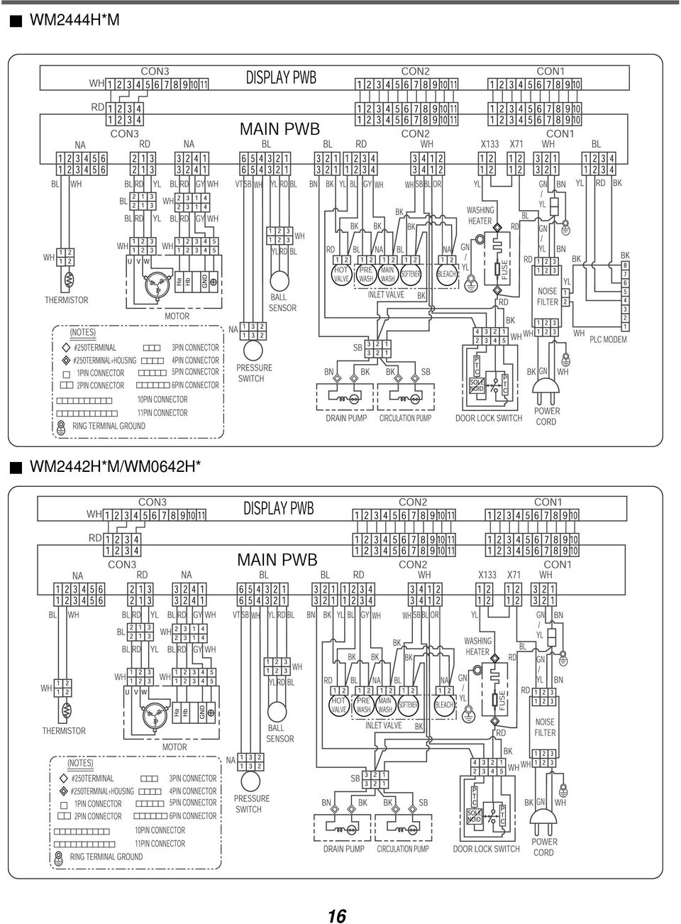
16 6. WIRING DIAGRAM / PROGRAM CHART WM2411HW / WM2011HS / WM2011HW / WM2432HW / WM2032HS / WM2032HW / WM0532HW / WD-10210BD / WD-12210(5)BD WM1811CW / WM1832CW 15
BD")
17 WM2444H*M WM2442H*M/WM0642H* 16
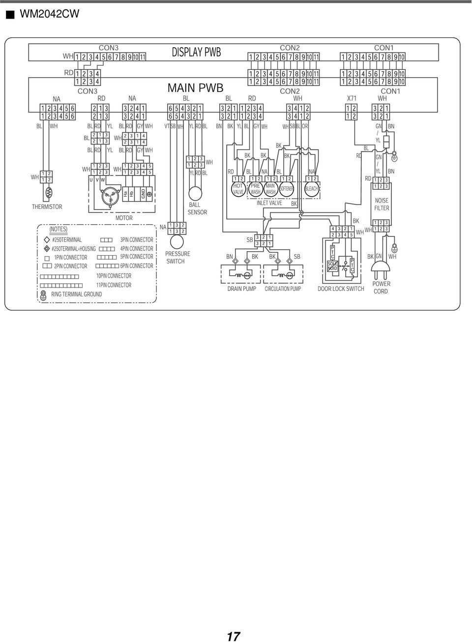
18 WM2042CW 17
19 18

20 7. TROUBLESHOOTING 7-1. BEFORE PERFORMING SERVICE Be careful of electric shock when disconnecting parts for while troubleshooting. The voltage of each terminal is 120V AC and DC when the unit is plugged in QC TEST MODE. The washer must be empty and the controls must be in the off state. ÁPress the SPIN SPEED and SOIL LEVEL buttons simultaneously. ŁPress the Power button, while the above condition. Then buzzer sound twice. ØIn order to advance to the next step of test mode, press the START / PAUSE button once. Number of times the Start/Pause button is pressed None Check Point Turns on all lamps and locks the door. Display Status 1 time Tumble clockwise. rpm (40~50) 2 times Low speed Spin. rpm 3 times High speed Spin. rpm 4 times Inlet valve for prewash turns on. Water level frequency (25~65) 5 times Inlet valve for main wash turns on. Water level frequency (25~65) 6 times Inlet valve for hot water turns on. Water level frequency (25~65) 7 times Inlet valve for softener turns on. Water level frequency (25~65) 8 times Inlet valve for bleach turns on. Water level frequency (25~65) 9 times Tumble counterclockwise. rpm (40~50) 10 times Heater turns on for 3 sec. Water temperature 11 times Circulation pump turns on. Water level frequency (25~65) 12 times Drain pump turns on. Water level frequency (25~65) 13 times Power off and unlock the door. Turn off all lamps. WM2411HW WM2011HS / WM2011HW WM1811CW WM2432HW WM2032HS / WM2032HW WM1832CW WD-12210(5)BD WM0532HW / WD-10210BD 7-3. HOW TO CHECK THE WATER LEVEL FREQUENCY Press the SPIN SPEED and SOIL LEVEL button simultaneously. The digits indicate the water level frequency ( x.1 khz ). So, for example a display indicating 241 : a Water level frequency of 241 x.1 khz = 24.1 khz 19

21 7-4. ERROR DISPLAY If you press the START/PAUSE button when an error is displayed, any error except will disappear and the machine will go into the pause status. In case of if the error is not resolved within 20 sec., or the in case of other errors, if the error is not resolved within 4 min., power will be turned off automatically and the error code will blink. But in the case of, power will not be turned off. ERROR SYMPTOM CAUSE 1 2 WATER INLET ERROR IMBALANCE ERROR Correct water level (2 level) is not reached within 8 minutes after water is supplied or it does not reach the preset water level within 25 minutes. The load is too small. The appliance is tilted. Laundry is gathered to one side. Non distributable things are put into the drum. 3 DRAIN ERROR Not fully drained within 10 minutes. 4 OVER FLOW ERROR Water is overflowing (over 8 level). If is displayed, the drain pump will operate to the drain water automatically. 5 6 PRESSURE SENSOR ERROR DOOR OPEN ERROR The SENSOR SWITCH ASSEMBLY is out of order. Door not all the way closed. Loose electrical connections at Door switch and PWB Assembly. The DOOR SWITCH ASSEMBLY is out of order. 7 HEATING ERROR The THERMISTOR is out order. 20
22 ERROR SYMPTOM CAUSE OVER CURRENT ERROR LOCKED MOTOR ERROR BALL SENSOR ERROR EEPROM ERROR MAIN PWB ASSEMBLY is out of order. Winding in the STATOR ASSEMBLY is short-circuited. The connector (3-pin, male, white) in the MOTOR HARNESS is not connected to the connector (3-pin, female, white) of STATOR ASSEMBLY. The electric contact between the connectors (3-pin, male, white) in the MOTOR HARNESS and 4-pin, female, white connector in the MAIN PWB ASSEMBLY is bad or unstable. The MOTOR HARNESS between the STATOR ASSEMBLY and MAIN PWB ASSEMBLY is cut (open circuited). The hall sensor is out of order/defective. Loose Ball Sensor Connector. Ball Sensor is out of order. Displayed only when the START / PAUSE button is first pressed in the QC Test Mode. EEPROM is out of order. Displayed only when the START / PAUSE button is first pressed in the QC Test Mode. 12 POWER FAILURE The washer experienced a power failure. 21
23 8. ERROR DIAGSIS AND CHECK LIST 8-1.DIAGSIS AND SOLUTION FOR ABRMAL OPERATION SYMPTOM GUIDE FOR SERVICE CALL No power Is the power plug connected firmly to 120V AC outlet? Power failure? or Breaker opened? Is the outlet controlled by a switch? Visit to service. Water inlet trouble Is displayed? Is the tap opened? Is the tap frozen? Is the water supply shut-off? Is filter in the inlet valve clogged with foreign material? Clean the filter of inlet valve Visit to service. 22
24 SYMPTOM GUIDE FOR SERVICE CALL Door error Was the load too large? Visit to service. Drain trouble Visit to service. 23
25 SYMPTOM GUIDE FOR SERVICE CALL Suds overflow from the appliance. (In this condition, wash and spin do not operate normally) Is a low-sudsing detergent used? Is the proper amount of detergent used as recommended? Recommend to reduce the amount of detergent. LOW-SUDSING This appliance has an automatic suds sensing function which prevents overflow. When excessive suds are sensed, the suds removing implementations such as drain, water input, pause will operate, without rotating the drum. No softening effect Is softener put in the correct compartment of the dispenser? Compartment for softener Is the softener cap clogged? Explain proper use of softener. Clean the softener compartment Visit to service. 24
26 8-2.FAULT DIAGSIS AND TROUBLESHOOTING CAUTION 1. Be careful of electric shock if disconnecting parts while troubleshooting. 2. First of all, check the connection of each electrical terminal with the wiring diagram. 3. If you replace the MAIN PWB ASSEMBLY, reinsert the connectors correctly. POWER Is the supplied voltage 120V AC? Check the fuse or reset the circuit breaker. Connector Is the voltage between the 2 FILTER ASSEMBLY connectors 120V AC? Replace the FILTER ASSEMBLY (CIRC). Is the LED(1) on? Replace MAIN PWB ASSEMBLY. Are the connectors(2) on the PWB loose? Reconnect. Is wire of the DISPLAY PWB ASSEMBLY broken? Replace the MAIN PWB ASSEMBLY. Replace DISPLAY PWB ASSEMBLY or repair wire. 25
27 WATER SUPPLY Is water supply shut-off? Is the tap opened? When you press both SPIN SPEED button and SOIL LEVEL button simultaneously, is the water level frequency below 246? Is the inlet valve filter clogged? Is resistance between each terminal of INLET VALVE ASSEMBLY kΩ? Open the tap. Check the AIR CHAMBER and the tube (clogged). Clean the filter. Replace the INLET VALVE ASSEMBLY. Verify the voltage of the inlet valve connector is 120V AC. (Refer to 7-2 QC TEST MODE) Check electrical connection. Replace the MAIN PWB ASSEMBLY. DETERGENT DOES T FLOW IN Is water supplied? Refer to WATER SUPPLY Are receptacles correctly connected to the terminals of the INLET VALVE ASSEMBLY? Has detergent been put in the correct compartment of the dispenser? Check the wiring. Put the detergent in the correct place. Is the detergent caked or hardened? Clean the dispenser. 26
28 SOFTENER / BLEACH DOES T FLOW IN Is water supplied? Refer to WATER SUPPLY Are the plugs correctly connected to the terminals of the INLET VALVE ASSEMBLY? Check the wiring on the dispenser. Is softener / bleach put in the correct compartment of the drawer? Put it in the correct compartment. Is the softener / bleach cap clogged? Clean the Cap and Container. ABRMAL SOUND Is the motor bolt loosened? Secure the bolt. Is there friction noise coming from the motor? Replace the STATOR ASSEMBLY or ROTOR ASSEMBLY. 27
29 HEATING WITHOUT WATER When pressing SPIN SPEED and SOIL LEVEL at the same time after draining, is the water level frequency 255? When pressing SPIN SPEED and SOIL LEVEL buttons at the same time while wash, is the water level frequency between ? Replace the SENSOR SWITCH ASSEMBLY. Check the voltage between two pins while pressing the POWER button. Is the voltage 120V AC? Replace the MAIN PWB ASSEMBLY. DRAIN MALFUNCTIONING Is the drain hose twisted or frozen? Repair the DRAIN HOSE ASSEMBLY. Is the impeller of the drain pump clogged? Remove foreign material. Is the connector disconnected, disassembled? Reconnect or repair the connector Is the coil of the drain pump too high or low? (resistance of coil is 10-20Ω) Replace the DRAIN PUMP ASSEMBLY. When checking voltage between connectors during spin, is the voltage 120V AC as in the figure? Replace the MAIN PWB ASSEMBLY. 28
30 WASH HEATER TROUBLE HEATING CONTINUOUSLY ABOVE THE SETTING WATER TEMPERATURE When checking the THERMISTOR on the tub, is the THERMISTOR loose? Push the THERMISTOR tightly to the rubber. 29
31 WILL T CIRCULATE WATER Is the impeller of the drain pump clogged? Remove foreign material. Hose Hose Connector (White) Are the Hose Connector and/or Hose clogged? Remove foreign material. Connector Is the connector disconnected, disassembled? Reconnect or repair the connector. Connector Is the coil of the right side of drain pump open or short circuited? (Coil R is 18-30Ω) Replace PUMP MOTOR ASSEMBLY. When checking voltage between the connectors during spin, is the voltage 120V AC, as the figure? Replace the MAIN PWB ASSEMBLY. 30
32 SPIN TROUBLE Check during spin if the frequency of the water level is 248 or more. Check the SENSOR SWITCH ASSEMBLY or HOSE (Pressure). If the problem is on the SENSOR SWITCH ASSEMBLY or the HOSE, replace the SENSOR SWITCH ASSEMBLY or the HOSE. Press the START / PAUSE button 2 times in QC Test mode, is the drum spinning at low speed? Normal Is it disconnected, or disassembled? [Red:3pin (1), NA:4pin (2)] Correct the connection. Check the motor connector, Is the resistance of the terminal the same as the figure? MOTOR TERMINAL N M L Resistance of terminal: L- M / M- N / N- L About 5Ω 15Ω Replace the STATOR ASSEMBLY Replace the MAIN PWB ASSEMBLY Does the spring of Latch Hook actuate? Replace Door Assembly. Is there clicking sound once or twice when the START/PAUSE button is pressed to start the cycle? Check the DOOR SWITCH ASSEMBLY Connector and MAIN PWB ASSEMBLY (Red 4 pin and white 4 pin connector (1)). Is DOOR SWITCH ASSEMBLY broken? Replace the DOOR SWITCH ASSEMBLY. 31
33 9. DISASSEMBLY INSTRUCTIONS ƒr Disassemble and repair the unit only after pulling out power plug from the outlet. 1. Unscrew 7 screws on the Rear Frame. 2. Disassemble the Rear Frame. 3. Pull the Control panel forward. 4. Disconnect connectors. 5. Unscrew 5 screws. 6. Disassemble the controller assembly. 1. Open the Lid. LID 2. Unscrew 4 screws. 3. Disassemble the Lid Assembly. 4. Pull down the Dispenser by pushing hooks. 5. Put a hand into the dispenser hole and hold the top plate. 6. Push backward using an opener and lift the top plate. Do first left side ( L). 32
34 1. Disassemble the 5 hose clamps. 2. Release the 5 hoses. 3. Unscrew the nut at the lower part of the dispenser. 4. Unscrew the 4 screws on the holder. 5. Disassemble the 5 connectors from the valves. Wire color : L WH-BK M OR-BK N WH-BK O GY-BK P BL-BK 1. Unscrew the screw from the top plate. 2. Unplug the 2 connectors. 33
35 1. Unscrew the 2 screws from upper side of the cabinet cover. 2. Unscrew the screw from filter cover. 3. Put a flat ( ) screwdriver into the both sides of the filter cover, and pull it out. 4. Unscrew the 2 screws from the lower side of the cabinet cover. 34
36 5. Open the door. 6. Disassemble the clamp assembly using a flat ( ) screwdriver. Clamp Assembly 7. Separate the clamp assembly from cabinet cover. 8. Tilt the cabinet cover. 9. Disconnect the door switch connector. 10. Lift and separate the cabinet cover. 11. Disassemble the clamp assembly using a flat ( ) screwdriver. 12. Disasemble the Gasket. 35
37 1. Open the door. 2. Unscrew the 7 screws from the hinge cover. 3. Put a flat ( ) screwdriver into the opening of the hinge, and pull out the hinge cover. 4. Unscrew the screws from the door. 5. Disassemble the door upward / downward. Be careful! The door is heavy. 1. Open the door. 2. Disassemble the clamp assembly. 3. Unscrew the 2 screws from cabinet cover. 36
38 1. Disassemble the cabinet cover. 2. Separate the pump hose, the bellows and the circulation hose assembly from the pump assembly. 3. Disassemble the pump assembly in arrow direction. 1. Disassemble the cabinet cover. 2. Separate 2 connectors from the heater. 3. Loose the nut and pull out the heater. CAUTION When assembling the heater, insert the heater into heater clip on the bottom of the tub. Tighten the fastening nut so the heater is secure. 1. Disassemble the cabinet cover. 2. Unplug the white connector from the thermistor. 3. Pull it out by holding the bracket of thermistor. 37
39 1. Disassemble the cabinet cover. 2. Separate the heater from the tub. 3. Remove any foreign objects (wire, coin, etc.) by inserting a long bar in the opening. 1. Unscrew the 4 screws from the back cover. 2. Unscrew the single screw from the lower-right side of the cabinet. 3. Disconnect the connector from PWB Harness. 38
40 1. Disassemble the back cover. 2. Loosen the bolt. 3. Pull out the Rotor. 4. Unscrew the 2 screws from the tub bracket. 5. Loosen the 6 bolts on the stator. 6. Unplug the 2 connectors from the stator. 1. Disassemble the damper hinges from the tub and base. 2. Separate the dampers. TE Once removed, replace the damper pin with new one. 39
41 10. EXPLODED VIEW CABINET & CONTROL PANEL ASSEMBLY A125 A160 A105 F215 A490 A495 A154 A136 A303 40
42 10-2. DRUM & TUB ASSEMBLY K123 K115 K111 F463 F464 K125 K122 K121 K101 K343 F315 F463 K340 K344 K345 F141 K105 41
43 10-3. DISPENSER ASSEMBLY F302 F301 F170 F160 F300 F324 F325 F323 A275 HOT (BLUE) F321 F322 A276 COLD (RED) F436 F431 F120 F441 F440 F430 F435 F432 42
WASHING MACHINE READ THIS MANUAL CAREFULLY TO DIAGNOSE TROUBLE CORRECTLY BEFORE OFFERING SERVICE.
 website : http://www.lgeservice.com e-mail : http://lgeservice.com/techsup.html WASHING MACHINE SERVICE MANUAL CAUTION READ THIS MANUAL CAREFULLY TO DIAGSE TROUBLE CORRECTLY BEFORE OFFERING SERVICE. MODEL
All About. Servicing. Service Tech Hand Book. 2010 Electrolux Home Products Inc. 10200 David Taylor Drive Charlotte, NC 28262
 All About Servicing Service Tech Hand Book 2010 Electrolux Home Products Inc. 10200 David Taylor Drive Charlotte, NC 28262 Publication #5995588729 February 2011 Section 1 Basic Information Safe Servicing
Error Codes: 02F. Model: 110.44832 200 (110. = Whirlpool) S/N: CSP 1903874 Type: 199-AKP 705/WT. Sears Kenmore/Whirlpool Front Load Washer
 S/N: CSP 1903874 Type: 199-AKP 705/WT. Sears Kenmore/Whirlpool Front Load Washer") Sears Kenmore/Whirlpool Front Load Washer Error Codes: 02F dlf Model: 110.44832 200 (110. = Whirlpool) S/N: CSP 1903874 Type: 199-AKP 705/WT SOURCE: www.applicancepartspros.com WHIRLPOOL FAULT CODES Whirlpool
Sears Kenmore/Whirlpool Front Load Washer Error Codes: 02F dlf Model: 110.44832 200 (110. = Whirlpool) S/N: CSP 1903874 Type: 199-AKP 705/WT SOURCE: www.applicancepartspros.com WHIRLPOOL FAULT CODES Whirlpool
OPL BASIC. Dosing System for Professional Laundry machines. Contents
 OPL BASIC Dosing System for Professional Laundry machines Contents 1 Getting Started. Page 2 2 Installation. Page 4 3 Set Up & Operation. Page 8 4 Maintenance & Accessories. Page 10 5 Troubleshooting Page
Fully Automatic Washing Machine User manual
 Fully Automatic Washing Machine User manual This manual is for HWMP55-918 Please read this manual carefully before using. Retain it for future reference. CONTENTS CONTENTS Inside cover Parts 1 Safety precautions
TOP AND CABINET PARTS
 TOP AND CABINET PARTS AUTOMATIC WASHER 9 06 Printed in U.S.A. (drd) 1 Part No. Rev. A TOP AND CABINET PARTS 1 Literature Parts 8182271 Use & Care Guide 8182277 Tech Sheet 8182614 Energy Guide 8182196 Quick
Service manual. Website: www.andico.com.au CAUTION - BEFORE SERVICING THE UNIT, READ THE SAFETY - PRECAUTIONS IN THIS MANUAL.
 Website: www.andico.com.au Service manual CAUTION - BEFORE SERVICING THE UNIT, READ THE SAFETY - PRECAUTIONS IN THIS MANUAL. - ONLY FOR AUTHORISED SERVICE PERSONNEL. MODELS: MPK1-09CR-QB8 MPK1-12ER-QB6
BUILT-IN DISHWASHER INSTALLATION INSTRUCTIONS
 BUILT-IN DISHWASHER INSTALLATION INSTRUCTIONS PLEASE READ COMPLETE INSTRUCTIONS BEFORE YOU BEGIN LEAVE INSTALLATION INSTRUCTIONS AND USER'S GUIDE WITH OWNER ALL ELECTRIC WIRING AND PLUMBING MUST BE DONE
WASHING MACHINE READ THIS MANUAL CAREFULLY TO DIAGNOSE PROBLEMS CORRECTLY BEFORE SERVICING THE UNIT.
 Website: http: //www.lgeservice.com E-mail: http: //www.lgeservice.com/techsup.html WASHING MACHINE SERVICE MANUAL! CAUTION READ THIS MANUAL CAREFULLY TO DIAGSE PROBLEMS CORRECTLY BEFORE SERVICING THE
PRODUCT: WASHER / WASHER-DRYER COMBO MODEL: AW 120 / AW 122 / AW 125 AWD 120 / AWD 121 / AWD 129
 PRODUCT: WASHER / WASHER-DRYER COMBO MODEL: The information included in this Splendide Repair Manual may change without notice. Please see our web site www.splendide.com/service/docs.html for updates,
Portable Air Conditioner
 Portable Air Conditioner Owner's Manual Model:3 in 1 12,000 Btu/h Series 3 Please read this owner s manual carefully before operation and retain it for future reference. CONTENTS 1. SUMMARY...1 2. PORTABLE
EVANS ELECTRONIC TEMPERATURE CONTROL TROUBLESHOOTING GUIDE for systems equipped with electric coolant valve and external PC board.
 EVANS ELECTRONIC TEMPERATURE CONTROL TROUBLESHOOTING GUIDE for systems equipped with electric coolant valve and external PC board. This Troubleshooting Guide covers the electric coolant valve and control
Please read this manual carefully before using. Retain for future reference. Automatic Washing Machine User manual
 Automatic Washing Machine User manual This manual is for HWMP55-918 HWMP65-918 Please read this manual carefully before using. Retain for future reference. CONTENTS Product Overview 1 Safety Precautions
Cooling system components, removing and installing
 Engine BHW Cooling system components, removing and installing Page 1 / 24 19-1 Cooling system components, removing and installing Warning! When doing any repair work, especially in the engine compartment,
Thermo Top - Troubleshooting Tree
 Thermo Top - Troubleshooting Tree 07-15-2002 CAUTION Troubleshooting requires comprehensive knowledge about the structure and theory of operation of the Thermo Top heater. Troubleshooting and repairs may
USER INSTRUCTIONS FOR 10 LITRE PORTABLE DEHUMIDIFIER MODEL NO. DHMD102
 USER INSTRUCTIONS FOR 10 LITRE PORTABLE DEHUMIDIFIER MODEL NO. DHMD102 THANK YOU FOR CHOOSING YOUR NEW DEHUMIDIFIER. BEFORE USING THE UNIT READ THESE INSTRUCTIONS FULLY AND RETAIN THEM FOR FUTURE REFERENCE
800-292-3279 916 638-0828
 800-292-3279 916 638-0828 http://easycleansystems.com/heaters/heater-parts.html VAL6 KBE5S and KBE5L Service manual KBE5S 1 2 Specifications Type VAL6 KBE5S Heat Output 111,000BTU/h Fuel Kerosene, Diesel
Cooling system components, removing and installing
 Page 1 of 34 19-1 Cooling system components, removing and installing WARNING! The cooling system is pressurized when the engine is warm. When opening the expansion tank, wear gloves and other appropriate
Operating Manual. Los Angeles Abrasion Machine HM-70A & HM-70AF
 Operating Manual Los Angeles Abrasion Machine HM-70A & HM-70AF Rev: 07/19/2012 PHONE: 800-444-1508 P.O. Box 200, Lewis Center, Ohio 43035-0200 FAX: 800-255-5314 740-548-7298 E-mail: [email protected]
TOP AND CABINET PARTS For Models: WTW5500XW0, WTW5500XL0 (White) (Silver)
 (Silver)") TOP AND CABINET PARTS AUTOMATIC WASHER 5 10 Litho in U.S.A. (drd)(bay) 1 Part No. Rev. A TOP AND CABINET PARTS 1 Literature Parts Installation Instructions W10240509 English/French W10240510 Spanish W10280477
TOP AND CABINET PARTS AUTOMATIC WASHER 5 10 Litho in U.S.A. (drd)(bay) 1 Part No. Rev. A TOP AND CABINET PARTS 1 Literature Parts Installation Instructions W10240509 English/French W10240510 Spanish W10280477
TS93 EMR T/PT/TDE. Surface applied door closer
 TS EMR T/PT/TDE Surface applied door closer Installation instructions: Pull side track mount door closer with smoke detector (EMR T) Push side track mount door closer with smoke detector (EMR PT) Double
Service Guide 12/27/03 TESTING, SERVICE & REPAIR GUIDE (For SH Space Heating Models & RA Water Heating Models)
") TESTING, SERVICE & REPAIR GUIDE (For SH Space Heating Models & RA Water Heating Models) WARNING - HIGH VOLTAGE AC electrical circuits are connected to this heater. Do not attempt any service work on the
TESTING, SERVICE & REPAIR GUIDE (For SH Space Heating Models & RA Water Heating Models) WARNING - HIGH VOLTAGE AC electrical circuits are connected to this heater. Do not attempt any service work on the
Troubleshooting Guide for Dispenser Model #900172
 Troubleshooting Guide for Dispenser Model #900172 Q. The cold water is room temperature. A. There is a cold water thermostat control mounted to the back of the majority of our appliances. Simply unplug
Instruction Manual. Image of SP-3015 & SP-3815. Important Safeguards. Automatic Dispensing Hot Water Pot with Reboil Function
 Important Safeguards READ ALL INSTRUCTIONS BEFORE USE. Instruction Manual Automatic Dispensing Hot Water Pot with Reboil Function Image of SP-3015 & SP-3815 SP-3015: 3.0L SP-3815: 3.8L SP-3017: 3.0L (Stainless
Dehumidifier Users manual. For Models: DH45S DH65S
 Dehumidifier Users manual For Models: DH45S DH65S 950-0062-revD Jan. 9 2007 FORWARD The appearance of the units that you purchase might be slightly different from the ones described in the Manual, but
Installation Instructions 4508 4508S
 SYMPHONY Spread Lavatory Faucet with Speed Connect Drain Congratulations on purchasing your American Standard faucet with Speed Connect drain, a feature found only on American Standard faucets. Speed Connect
MACBlower Model Number: MAC40R MAC60R MAC80R MAC100R. MAC120R MAC150R MAC 200R Serial # www.macblowers.com
 MACBlower Model Number: MAC40R MAC60R MAC80R MAC100R MAC120R MAC150R MAC 200R Serial # Fuji Clean USA 41-2 Greenwood Road Brunswick, Maine 04011 207-406-2729 www.macblowers.com MACBlowers The Intelligent
TOP AND CABINET PARTS
 TOP AND CABINET PARTS AUTOMATIC WASHER 10 10 Litho in U.S.A. (drd) (psw) 1 Part No. W10337313 Rev. C TOP AND CABINET PARTS 1 Literature Parts Installation Instructions W10240509 English/French W10240510
ENGINE FUEL FUEL FILTER... FUEL HEATER... INJECTOR... SUPPLY PUMP... COMMON RAIL... FUEL PRESSURE LIMITTER...
 FUEL FILTER............................ FUEL HEATER.......................... INJECTOR.............................. SUPPLY PUMP.......................... COMMON RAIL.......................... FUEL PRESSURE
Table of Contents. www.hunterfan.com. What to Expect with. Preparation. Tools Needed. Wiring. Hanging the Fan. Blades. Motor Housing.
 www.hunterfan.com Table of Contents What to Expect with Your Installation 30 inches Hanging the Fan Wiring 8 Maintenance, Operation & Cleaning Light Kit 13??? 14 1 9 Troubleshooting 11 5 Blades Motor Housing
Fleck 4650. Service Manual INSTALLATION AND START-UP PROCEDURE TABLE OF CONTENTS JOB SPECIFICATION SHEET
 Fleck 4650 Service Manual TABLE OF CONTENTS JOB SPECIFICATION SHEET...1 INSTALLATION AND START-UP PROCEDURE...1 CONTROL VALVE DRIVE ASSEMBLY...2 CONTROL DRIVE ASSEMBLY FOR CLOCK...3 BYPASS VALVE ASSEMBLY...4
POSEIDON 2-29, 2-25 & 2-22 POSEIDON 2-29, 2-25 & 2-22 XT
 POSEION 2-29, 2-25 & 2-22 POSEION 2-29, 2-25 & 2-22 XT Repair Manual Index A. Safety precautions 3 B. Technical data 4 C. Structure 5-6. Service / Repair 7-23 E. Tools 24 F. Function 25-26 G. Electric
Name of Equipment Silver King Model SKMCD1P/C1. This equipment chapter is to be inserted in the appropriate section of the Equipment Manual.
 Name of Equipment Silver King Model SKMCD1P/C1 This equipment chapter is to be inserted in the appropriate section of the Equipment Manual. Manufactured exclusively for McDonald s By Silver King Refrigeration,
USER INSTRUCTIONS FOR GET PORTABLE 12k BTU AIR CONDITIONER MODEL No. GPACU12HR
 USER INSTRUCTIONS FOR GET PORTABLE 12k BTU AIR CONDITIONER MODEL No. GPACU12HR CONTENTS Introduction Safety Notes Identification of parts Installation instructions Operation instructions Maintenance Troubleshooting
Portable Evaporative Air Cooler. OWNER S MANUAL Read and save these instructions before use. Model: CL30XC
 Portable Evaporative Air Cooler OWNER S MANUAL Read and save these instructions before use Model: CL30XC Power rating: 250 Watts Voltage rating: 230 Volt, 50Hz Made in P.R.C. QUICK START GUIDE Fill with
LUCCI AIRFUSION QUEST II CEILING FAN
 LUCCI AIRFUSION QUEST II CEILING FAN WITH IR REMOTE INSTALLATION OPERATION MAINTENANCE WARRANTY INFORMATION CAUTION READ INSTRUCTIONS CAREFULLY FOR SAFE INSTALLATION AND FAN OPERATION. V1.0 QUEST II IR
DIAMOND Retractable Rodding Robot Model SPRAYROD-R
 2004-12-21 2 1 (23) DIAMOND Retractable Rodding Robot Model SPRAYROD-R 2004-12-21 2 2 (23) Table of contents 1 TECHNICAL DESCRIPTION...4 1.1 MAIN DETAILS...5 1.2 COMPONENTS DESCRIPTION...5 1.2.1 Pneumatic
SunMaxx Solar Filling Station Operating Instructions
 SunMaxx Solar Filling Operating Instructions Content 1. Declaration of conformity... 2 2. Introduction... 2 3. Transportation and unpacking... 4 4. Mounting and commissioning... 5 5. End of operation...
PWC-500/1000/1010/1500
 SERVICE MANUAL for by Vertex Model PWC-500/1000/1010/1500 P/N man-7008 Table of Contents Introduction Cooler Set-up Remove Top Cover Remove/Replace Float Remove/Replace Hot Tank Faucet Repair Hot Tank
JANUS INTERNATIONAL CORPORATION INSTALLATION INSTRUCTIONS Pantheon Mini Operator
 JANUS INTERNATIONAL CORPORATION INSTALLATION INSTRUCTIONS Pantheon Mini Operator The Janus Pantheon mini operator does not typically require the provision of any additional site requirements other than
Nexus FS Point of Use Installation Guide
 Nexus FS Point of Use Installation Guide Nexus FS POU Install Guide:12152011:rev-12152011 Technical Specifications Dimensions: Height: 43.5 Width: 11.65 Depth: 15 Weight: 34.39 LBS Electrical Specs: Voltage:
Twin-tub Washing Machine
 Twin-tub Washing Machine SERVICE MANUAL MODEL NO.: DW-1100K NINGBO KINGSUN GROUP CO., LTD Please read this manual carefully before operating your Washing Machine. Please record model number and serial
3. SEISCO PARTS & SERVICE REMOVAL AND REPAIR GUIDE
 4 3. SEISCO PARTS & SERVICE REMOVAL AND REPAIR GUIDE A. Changing the Control Board B. Replacing a Heating Element C. Thermistor Replacement D. High Limit Switch Replacement E. Level Detector Replacement
CDS TROUBLESHOOTING SECTION I. VACUUM. 1.0. Weak vacuum at wand. Gauge reads normal (10hg to 14hg)
") CDS TROUBLESHOOTING SECTION I. VACUUM 1.0. Weak vacuum at wand. Gauge reads normal (10hg to 14hg) 1.1. Clogged hoses or wand tube. Disconnect hoses and carefully check for an obstruction. 1.2. Excessive
CDS TROUBLESHOOTING SECTION I. VACUUM 1.0. Weak vacuum at wand. Gauge reads normal (10hg to 14hg) 1.1. Clogged hoses or wand tube. Disconnect hoses and carefully check for an obstruction. 1.2. Excessive
MODEL T600 40LB CAPACITY COMPUTER CONTROL COIN WASHER
 P/N 8514-097-001B MODEL T600 40LB CAPACITY COMPUTER CONTROL COIN WASHER DEXTER LAUNDRY, INC. OWNER'S BOOKLET INSTALLATION & OPERATION INSTRUCTIONS Please read this information and retain for reference.
Service Manual. Coffee maker Senseo Viva Café HD7825/30 10/05. Philips Consumer Lifestyle
 Coffee maker Senseo Viva Café Philips Consumer Lifestyle Service Manual PRODUCT INFORMATION - This product meets the requirements regarding interference suppression on radio and TV. - After the product
GPS AutoSteer System Installation Manual
 GPS AutoSteer System Installation Manual Supported Vehicles John Deere Sprayers 4720 4630 4730 4830 AutoTrac Ready PN: 602-0227-01-A LEGAL DISCLAIMER Note: Read and follow ALL instructions in this manual
Oil and Coolant Circulating Heating System. Model - OCSM
 Oil and Coolant Circulating Heating System Model - OCSM Installation & Operation Manual 216280-000 REV 2 Identifying Your System The HOTSTART heating system is designed to heat fluids for use in marine
INSTALLATION INSTRUCTIONS
 INSTALLATION INSTRUCTIONS Accessory Application Publications No. AII23628 2003 PILOT Issue Date MAY 2002 PARTS LIST Security System Kit (sold separately): P/N 08E51-S84-100 2 Remote controls Attachment
Convection Ovens. BX Classic. Models BX4 / FG 189C, BX4-6040 / FG 158C, BX10 / FG 180C. Operator's Manual
 Convection Ovens BX Classic Models BX4 / FG 189C, BX4-6040 / FG 158C, BX10 / FG 180C Operator's Manual Belshaw Bros., Inc. 814 44 th Street NW, Suite 103 Auburn, WA 98001 USA Phone: 206-322-5474 Fax: 206-322-5425
IMPORTANT SAFETY RULES TO FOLLOW
 WARNING FLOOR & CARPET CLEANER Any piece of equipment can be dangerous if not operated properly. YOU are responsible for the safe operation of this equipment. The operator must carefully read and follow
Economy Combo Heat Press Manual Model No.: ECH-800
 Economy Combo Heat Press Manual Model No.: ECH-800 CONTENTS I. Assembly Drawing -----------------------------------------------------------------------------------2 II. Technical Parameters ------------------------------------------------------------------------------2
A.Y. McDonald Mfg. Co. Troubleshooting Submersible and Jet Pumps
 A.Y. McDonald Mfg. Co. Troubleshooting Submersible and Jet Pumps Troubleshooting Submersible Pumps Fuse overload or circuit breaker trips when motor is started 1. Incorrect line voltage. Check the line
Cleaning & Sanitisation
 Cleaning & Sanitisation Notice: The information and/or procedures presented in the following demonstration(s) should be performed by a trained Water Cooler Service Technician only. Never attempt to service
Bauknecht AG, Industriestrasse 36, 5600 Lenzburg, www.bauknecht.ch
 Instructions for use WA 5555 Bauknecht AG, Industriestrasse 36, 5600 Lenzburg, www.bauknecht.ch Verkauf Telefon 0848 801 002 Fax 0848 801 017 [email protected] Kundendienst Telefon 0848 801 001 Fax
123 Industrial Loop Road Paynesville, MN 56362 Phone: 1-800-864-1649 www.master-mfg.com MASTER MANUFACTURING MASTER GARDNER
 123 Industrial Loop Road Paynesville, MN 56362 Phone: 1-800-864-1649 www.master-mfg.com MASTER MANUFACTURING MASTER GARDNER Part Number PCD E3 009B MM Rev 1 Nov. 2010 INTRODUCTION The purpose of this manual
CARING FOR YOUR WATER HEATER
 http://waterheatertimer.org/troubleshoot-rheem-tankless-water-heater.html Water Heater Inspections CARING FOR YOUR WATER HEATER Venting System (Direct Vent Only) The venting system should be inspected
REMOVAL AND INSTALLATION
 303-01C-1 REMOVAL AND INSTALLATION Engine Body On Special Tool(s) Adapter For 303-D043 303-D043-02 or equivalent Special Tool(s) 303-01C-1 Turbocharger Lifting Bracket 303-1266 Wrench, Fan Clutch Nut 303-214
DANGER DANGER. General Information. Safety Is Your Responsibility. Ordering Parts. Contact Information
 Safety Safety Is Your Responsibility DANGER To avoid personal injury or death, carefully read and understand all instructions pertaining to the Anthony Liftgates product. Do not attempt to install, operate,
specializing in AIR CONDITIONING, PARTS AND SYSTEMS for your classic vehicle PERFECT FIT IN-DASH HEAT/ COOL/ DEFROST 1967-72 CHEVROLET PICKUP
 specializing in AIR CONDITIONING, PARTS AND SYSTEMS for your classic vehicle PERFECT FIT IN-DASH HEAT/ COOL/ DEFROST 1967-72 CHEVROLET PICKUP CONTROL & OPERATING INSTRUCTIONS The controls on your new Perfect
IMPORTANT SAFETY INSTRUCTIONS WARNING READ AND SAVE THESE OPERATING AND SAFETY INSTRUCTIONS BEFORE USING THIS HEATER.
 THERMAWAVE CERAMIC HEATER Model HZ-850 Series Model HZ-860 Series IMPORTANT SAFETY INSTRUCTIONS WARNING READ AND SAVE THESE OPERATING AND SAFETY INSTRUCTIONS BEFORE USING THIS HEATER. Warning Failure to
Washing Machine Owner s Instructions B1485AV/ B1285AV/ B1285AS/ B1285A/ B1085A/ R1285AV/ R1085A/ F1285AV/ F1085A
 Washing Machine Owner s Instructions B1485AV/ B1285AV/ B1285AS/ B1285A/ B1085A/ R1285AV/ R1085A/ F1285AV/ F1085A Safety Precautions Congratulations on your purchase of this Samsung washing machine. These
NO-FROST CUSTOMER SUPPORT INFORMATION INFORMATION ON THE NO-FROST TECHNOLOGY WHITE GOODS
 INFORMATION INFORMATION ON THE TECHNOLOGY The -Frost refrigerators are different from the other static refrigerators in terms of their operational system. In normal refrigerators, in the freezing section,the
Commercial code: 69068
 Model type: ARWXF129WNA Commercial code: 69068 General notes Technical Documentation guidelines ----------------------------------------------------------------------------------------------------------------------------------
SMD Rework Station TABLE OF CONTENTS
 SMD Rework Station Thank you for purchasing the Hakko 50B SMD Rework Station. The Hakko 50B is designed to solder and desolder surface mounted devices with hot air. Please read this manual before operating
COMMERCIAL TOP LOAD WASHER INSTALLATION, USER & SET-UP INSTRUCTIONS
 COMMERCIAL TOP LOAD WASHER INSTALLATION, USER & SET-UP INSTRUCTIONS MODELS: MAT12CS, MAT12PD, MAT13MN, MAT13PN LEAVE THESE INSTRUCTIONS WITH THE OWNER MAYTAG COMPANY, NEWTON, IOWA 50208 2207647 IMPORTANT
COLOR VIDEO DOOR PHONE CDV-71BE/D
 COLOR VIDEO DOOR PHONE CDV-71BE/D 513-11, Sangdaewon-dong, Jungwon-gu, Seongnam-si, Gyeonggi-do, Korea Int l Business Dept. : Tel.; +82-31-7393-540~550 Fax.; +82-31-745-2133 Web site : www.commax.com Printed
SERVICE MANUAL SPLIT SYSTEM ROOM AIR CONDITIONER SHARP CORPORATION SHARP CORPORATION CONTENTS
 SERVICE MANUAL SPLIT SYSTEM ROOM AIR CONDITIONER INDOOR UNIT AH-129 AH-MP14 OUTDOOR UNIT AU-129 AU-MP14 CONTENTS SPECIFICATIONS...2 EXTERNAL DIMENSIONS...4 WIRING DIAGRAMS...5 ELECTRICAL PARTS...6 MICROCOMPUTER
Ceiling Fan Installation Instructions
 Ceiling Fan Installation Instructions 1525..series OWNER S MANUAL READ AND SAVE THESE INSTRUCTIONS Total fan wieght with light kit 1-1525-CUL-English INSTALLATION CH-545 Safety Tips WARNING: TO REDUCE
Heat Surge Model X5C Fire Place Insert Service Manual Applies to all units w/30000208 circuit board
 Heat Surge Model X5C Fire Place Insert Service Manual Applies to all units w/30000208 circuit board 2012 HS M4417A BR16597R-1 HEAT SURGE 8000 FREEDOM AVE, N. CANTON, OH 44720 330-244-8161 WWW.HEATSURGE.COM
Gas Oven Repair Guide
 - /6 - Gas Oven Repair Guide [ FX70*, FX50*] Ver. Aug-0 Ignition Failure Cooktop ignition Oven ignition Heating defect Oven Cooktop Abnormal Flame Button, Motors Lamp Others Smell, Smoke, Noise No Display,
Installation and instruction manual for Laing DDC pumps
 Installation and instruction manual for Laing DDC pumps Application The Laing DDC series pumps are primarily used for the circulation of cooling liquid in liquid cooled computers. Construction - The Laing
Coffee Maker Senseo HD7820/70
 Coffee Maker Senseo Philips Domestic Appliances and Personal Care Service Manual PRODUCT INFORMATION - This product meets the requirements regarding interference suppression on radio and TV. - After the
Instruction manual for Firstline FCS12000CH
 Instruction manual for Firstline FCS12000CH Contents Introduction... 2 Safety Awareness... 3 Safety Awareness... 4 Name of Parts... 5 Name of Parts... 6 Remote Controller Preparation... 7 Operation of
MG1532 & MG2032 MIXER-GRINDERS
 MIXER-GRINDER MG1532 & MG2032 MIXER-GRINDERS MODEL MG1532 ML-134099 7.5 HP Grind Motor + 1 HP Mix Motor MG1532 ML-134103 5 HP Grind Motor + 1 HP Mix Motor MG1532 ML-134100 7.5 HP Grind Motor + 1 HP Mix
NewAir AC-10000E, AC-10000H Portable Air Conditioner Owner s Manual PLEASE READ AND SAVE THESE INSTRUCTIONS
 NewAir AC-10000E, AC-10000H Portable Air Conditioner Owner s Manual PLEASE READ AND SAVE THESE INSTRUCTIONS BEFORE USE GENERAL SAFETY INSTRUCTIONS: ALWAYS OPERATE THE UNIT IN AN UPRIGHT POSITION AND PLACE
Auto Sentry-eXP Maintenance
 Auto Sentry-eXP Maintenance Maintenance Procedures for Auto Sentry exp Bill Dispenser Credit Card Reader Bill Acceptor Bill Dispenser Maintenance Bill Dispenser Problem / Cause Bill Dispenser Error Codes
COOLING SYSTEM Section Page
 5 COOLING SYSTEM Section Page 5.1 COOLANT PRE-HEATER... 5-3 5.2 COOLANT PUMP NON-EGR ENGINE... 5-7 5.3 COOLANT PUMP EGR ENGINE... 5-13 5.4 FRONT CONNECTOR HOUSING NON-EGR ENGINE... 5-17 5.5 FRONT CONNECTOR
Bench Autoclave. Standard Operating Procedure. For Installation, Use and Maintenance
 Bench Autoclave Standard Operating Procedure For Installation, Use and Maintenance 1. Introduction This SOP is intended for use with the following model, in a laboratory context: Type: Nuve Bench Top Steam
Carpet Washer. vax.co.uk VRS5W. Vax Careline: (UK) 0844 412 8455 (ROI) 1-800 928 308. Vax model number: Version 1.0
 0844 412 8455 (ROI) 1-800 928 308. Vax model number: Version 1.0") VRS5W Powermax User Guide V1.0.qxd:V1.0 23/7/10 15:35 Page 1 Vax Careline: (UK) 0844 412 8455 (ROI) 1-800 928 308 Carpet Washer Vax model number: VRS5W instruction manual Version 1.0 Please read carefully
VRS5W Powermax User Guide V1.0.qxd:V1.0 23/7/10 15:35 Page 1 Vax Careline: (UK) 0844 412 8455 (ROI) 1-800 928 308 Carpet Washer Vax model number: VRS5W instruction manual Version 1.0 Please read carefully
Calor de Hogar. Av Tecnológico 735, PB. San Salvador Tizatlalli. Metepec, 52172, Edo de México. Teléfono (722) 216 3330 (55) 1163 6038
 216 3330 (55) 1163 6038") Calor de Hogar Av Tecnológico 735, PB San Salvador Tizatlalli Metepec, 52172, Edo de México Teléfono (722) 216 3330 (55) 1163 6038 www.calordehogar.com servicio@calordehogar. com [email protected]
Calor de Hogar Av Tecnológico 735, PB San Salvador Tizatlalli Metepec, 52172, Edo de México Teléfono (722) 216 3330 (55) 1163 6038 www.calordehogar.com servicio@calordehogar. com [email protected]
FlexFlash Instruction Manual Models SB FLXFLSH400W, SB FLXFLSH200W, SB FLXFLSHE400W, SB FLXFLSHE200W
 FlexFlash Instruction Manual Models SB FLXFLSH400W, SB FLXFLSH200W, SB FLXFLSHE400W, SB FLXFLSHE200W Rev 7/18/13 Accessory release button Flash tube Slave sensor Modeling lamp Repositionable swivel handle
Utility Distribution Systems
 Utility Distribution Systems 6/2012 A0011037 1 WARRANTY This equipment is warranted to be free from defects in materials and workmanship, under normal use and service, for a period of 12 months from date
SIBIR MANUAL V110 KE. English page 5 RKE - 1D 822 70 66-02
 SIBIR MANUAL RKE - 1D V110 KE English page 5 822 70 66-02 2 1 A. Flue tube E. Adapter I. Thermostat B. Flue baffle F. Burner base J. Lever arm C. Control knob G. Lamp glass D. Fuel gauge H. Lamp glass
SMART DRIVE ELECTRONIC WASHING MACHINE
 SMART DRIVE ELECTRONIC WASHING MACHINE MODEL GWL03US 120 Volt 60 Hz Fisher & Paykel Appliances Inc 27 Hubble, Irvine, California, CA92618, USA, Ph: 949 790 8900, Fax: 949 790 8911 426348 C O N T E N T
Water Tec of Tucson Water Systems
 Water Tec of Tucson Water Systems Water Filter Owner s Manual Water Tec of Tucson www.water-tec.com 4601 S. 3 RD Avenue Tucson, AZ 85714 (520) 790-1512 Fax (520) 745-0549 1 MAIN COMPONENTS Your water treatment
Max primary circuit temperature 90ºC Max primary circuit temp. 90ºC Max secondary circuit temperature 45ºC Max secondary circuit temp.
 EGLISH 1 Product description exchanger equipped with an electronic control unit and circulation pump for the primary circuit. All Aqua-Mex variants can be ordered with an interior coil of either titanium
Model 43AP Pneumatic Controller, Style B
 Instruction MI 011-476 January 1980 Model 43AP Pneumatic Controller, Style B Installation and Operation Model 43AP Controller continuously detects the difference between a process measurement and its set
FASCINATION 700 HVLP TANNING PRO SYSTEM USER MANUAL
 FASCINATION 700 HVLP TANNING PRO SYSTEM USER MANUAL Congratulations on choosing the Fascination 700 HVLP Tanning Pro System! Your system includes the following items: 1 Fascination 700 HVLP Tanning Pro
Line to Refrigerator Ice/Water Dispenser
 Standard 18 Line to Refrigerator Ice/Water Dispenser Pump Module Bottled Water How The System Works The FLOJET Bottled Water Dispensing System was designed to pump water from a commercially available 5-gallon
with MERCURY FREE 1 HP Relays ! WARNING Before using this product read and understand instructions.
 B Installation & Maintenance Instructions MM-414 Series 150E and 157E Low Water Cut-Off/Pump Controllers For Steam Boilers and Other Level Control Applications A Typical Applications: Primary or secondary
1. SAFETY RULES. 8. Avoid placing objects in the path of the blades.
 1 1. SAFETY RULES 1. To reduce the risk of electric shock, insure electricity has been turned off at the circuit breaker or fuse box before beginning. 2. All wiring must be in accordance with the National
15GAL STEEL OIL DRAIN WITH 110V PUMP
 15GAL STEEL OIL DRAIN WITH 110V PUMP OWNER S MANUAL WARNING: Read carefully and understand all ASSEMBLY AND OPERATION INSTRUCTIONS before operating. Failure to follow the safety rules and other basic safety
Quickie Rhapsody Service Manual
 Quickie Rhapsody Service Manual 2006 Sunrise Medical Inc. 101976 Rev A Quickie Rhapsody Service Manual Contents Introduction... 0.1 VR2 Controller... 0.2 Plugs/Connectors... 0.3 Basic Tool List & Main
SHOT BLAST CABINET MODEL NO: CSB20B
 SHOT BLAST CABINET MODEL NO: CSB20B PART NO: 7640110 USER INSTRUCTIONS GC0216 INTRODUCTION Thank you for purchasing this CLARKE Shot Blast Cabinet which is designed for professional workshop use. Before
PLEASE READ ALL INSTRUCTIONS BEFORE USE AND SAVE A COPY FOR FUTURE REFERENCE!
 PLEASE READ ALL INSTRUCTIONS BEFORE USE AND SAVE A COPY FOR FUTURE REFERENCE! 1. Read all instructions carefully before using the machine. 2. Do not touch hot surfaces. Use handles or knobs. The lid and
Use and Care Manual. Model CPA12KH AIR CONDITIONER
 Use and Care Manual Model CPA12KH AIR CONDITIONER Introduction Thank you for choosing this air conditioner to provide you and your family with all of the "Home Comfort" requirements for your home, cottage
Stainless Steel Single and Dual Circulation Kits
 Instruction Sheet P/N 160780 01 Stainless Steel Single and Dual Circulation Kits Introduction The single and dual high-pressure circulation kits allow you to vary and control the circulation rate of coating
Windshield Wiper System
 Volkswagen Golf 5 - Windshield Wiper System Volkswagen Technical Site: http://volkswagen.msk.ru http://vwts.info Page 1 / 15 92-1 Windshield Wiper System General information The windshield wiper system
Doorbell Intercom Security System
 Doorbell Intercom Security System POWER IN USE OFF A B C LOCK CALL TALK Installation Guide Model WHDB-301 EXPLANATION OF GRAPHIC WARNING SYMBOLS This symbol is intended to alert the user to the presence