WASHING MACHINE READ THIS MANUAL CAREFULLY TO DIAGNOSE PROBLEMS CORRECTLY BEFORE SERVICING THE UNIT.
|
|
|
- Hubert Montgomery
- 9 years ago
- Views:
Transcription
1 Website: http: // http: // WASHING MACHINE SERVICE MANUAL! CAUTION READ THIS MANUAL CAREFULLY TO DIAGSE PROBLEMS CORRECTLY BEFORE SERVICING THE UNIT. MODEL: WM2277H*/WM2077CW WM2177H*/WM2677H*M WD-11270BD 100

2 APR PRINTED IN KOREA P/No.:3828ER3018Y 101

3 CONTENTS 1. SPECIFICATIONS FEATURES & TECHNICAL EXPLANATION PARTS IDENTIFICATION INSTALLATION & TEST OPERATION WIRING DIAGRAM/PROGRAM CHART TROUBLESHOOTING BEFORE PERFORMING SERVICE QC TEST MODE HOW TO CHECK THE WATER LEVEL FREQUENCY ERROR DISPLAY ERROR DIAGSIS AND CHECK LIST DIAGSIS AND SOLUTION FOR ABRMAL OPERATION FAULT DIAGSIS AND TROUBLESHOOTING DISASSEMBLY INSTRUCTIONS EXPLODED VIEW CABINET & CONTROL PANEL ASSEMBLY DRUM & TUB ASSEMBLY DISPENSER ASSEMBLY

4 1. SPECIFICATIONS ITEM WM2677H*M WM2277H*/WD-11270BD WM2177H* WM2077CW COLOR W: BLUE WHITE, B: BLACK PEARL, S: TITANIUM POWER SUPPLY AC 120 V, 60 Hz PRODUCT WEIGHT 190 lbs. (86 kg) ELECTRIC POWER WASHING 280 W CONSUMTION DRAIN MOTOR 80 W WASH HEATER 1000 W WASH 42 rpm REVOLUTION SPEED SPIN rpm rpm rpm CYCLES 9 7 WASH/RINSE TEMPERATURES 5 SPIN SPEEDS 5 OPTIONS Prewash, Stain Cycle, Quick Cycle, Extra Rinse, Rinse+Spin, Delay Wash CUSTOM PROGRAM Incorporated WATER CIRCULATION Incorporated OPERATIONAL WATER PRESSURE psi ( kpa) CONTROL TYPE Electronic WASH CAPACITY [cu. ft.] 3.32 (3.83 IEC) 3.22 (3.72 IEC) DIMENSIONS 27 (W) X 29 3 / 4 (D) X / 16 (H), / 16 (D, door open) DELAY WASH up to 19 hours up to 12 hours up to 9 hours DOOR SWITCH TYPE PTC + Solenoid WATER LEVEL 10 steps (by sensor) LAUNDRY LOAD SENSING Incorporated ERROR DIAGSIS Incorporated AUTO POWER OFF Incorporated CHILD LOCK Incorporated RLM ENABLE Incorporated 3
 CONTROL TYPE Electronic WASH CAPACITY [cu. ft.] 3.32 (3.83 IEC) 3.22 (3.")
5 2. FEATURES & TECHNICAL EXPLANATION 2-1. FEATURES Direct Drive System The advanced Brushless DC motor directly drives the drum without belt and pulley. Tilted Drum and Extra Large Door Opening Tilted drum and extra large door opening make it possible to load and unload easily. Water Circulation Spray detergent solution and water onto the load repeatedly. Clothes are soaked more quickly and thoroughly during the wash cycle. Detergent suds are eliminated more easily by the water shower during rinse cycle. The water circulation system uses both water and detergent more efficiently. RollerJets Washing ball enhances wash performance and reduces damage to clothing. The jets spray and help tumble clothes to enhance washing performance while maintaining fabric care. Automatic Wash Load Detection Automatically detects the load and optimizes the washing time. Built-in Heater Internal heater automatically heats the water to the optimum temperature on selected cycles. Child Lock The Child lock feature prevents children from pressing any buttons to change the settings during operation. Using the RLM (Remote Laundry Monitor) The RLM monitors status of your washer and/or dryer. You can plug the display unit into any power outlet in your home. The RLM Display Unit can be purchased separately for this washer. 4

6 2-2. NEURO FUZZY WASHING TIME OPTIMIZATION To get the best washing performance, optimal time is determined by the water temperature, the selected washing temperature, and the size of the load. water temperature washing time selected washing temperature NEURO- FUZZY rinsing time the best washing performance load size spin rhythm, time SENSING PROCESSING DETERMINATION EFFECT 2-3. WATER LEVEL CONTROL This model incorporates a pressure sensor which can sense the water level in the tub. The water supply is stopped when the water level reaches the preset level, the washing program then proceeds. Spinning does not proceed until the water in the tub drains to a certain level DOOR CONTROL The door can be opened by pulling the door handle whenever washer is not in operation. When the cycle is completed, the DOOR LOCKED light will turn off. If a power failure has occurred while in operation, the door will unlock after 5 minutes. Clicking sounds can be heard when the door is locked/unlocked. 5

7 2-5. THE DOOR CAN T BE OPENED While program is operating When a power failed and power plug is taken out in operation While Door Lock lights turn on. White the motor is in the process of intertial rotating, through the operation is paused DOOR LOCKED LAMP LIGHTS When the frequency of water level is lower than 22.9 khz (It can be canceled when the frequency is more than 23.8 khz) When the temperature inside the tub is higher than 45 C and water level is not 25.5 khz (It can be canceled when the water level is 25.5 khz or the temperature inside the tub is lower than 40 C) 2-7. CHILD LOCK Use this option to prevent unwanted use of the washer. Press and hold PRE WASH button for 3 seconds to lock/unlock control. When Child lock is set, CHILD LOCK lights and all buttons are disabled except the Power lock the washer while it is operating. button. You can 2-8. WATER CIRCULATION When Washing and Rinsing function of shower at the upper part of Gasket. When Washing, it continuously operates for 3 minutes and intermittently. When Rinsing, it continuously operates after completion of water supply at first rinse. 6
 2-7. CHILD LOCK Use this option to prevent unwanted use of the washer.")
8 3. PARTS IDENTIFICATION Water Circulation Nozzle A Safety Cover (PLC Moderm) ACCESSORIES 7

9 4. INSTALLATION & TEST Before servicing, ask the customer what the trouble is. Check the setup (power supply is 120 V AC, remove the transit bolts...). Check with the troubleshooting guide. Plan your service method by referring to the disassembly instructions. Service the unit. After servicing, operate the appliance to see whether it functions correctly. STANDARD INSTALLATION The appliance should be installed as follows: REMOVE THE SHIPPING INSTALL THE APPLIANCE ADJUST THE BOLTS ON A FLAT AND FIRM SURFACE LEVELING Remove the 4 shipping bolts with the supplied wrench. Do first lower side to remove easily. Turn the leveling feet to adjust the appliance. Keep the shipping bolts and spanner for future use. Insert the 4 caps (provided) into the hole. Turn clockwise to raise; counterclockwise to lower. 8
 into the hole.")
10 HOW TO CONNECT THE INLET HOSE Verify that the rubber washer is inside of the valve connector. Tighten the inlet hose securely to prevent leaks. CONNECT THE DRAIN HOSE Make sure that the hose is not twisted. Avoid submerging the end of the hose. The end of the drain hose should be placed less than 96 from the floor. CONNECT POWER PLUG Connect the power plug to the wall outlet. Avoid connecting several electric devices, as doing so may cause a fire. 9

11 TEST OPERATION Preparation for Press the POWER button. Press the Start/Pause washing. button. Connect the power plug to the outlet. Connect the inlet hoses. Listen for a click to determine if the door has locked. Check the water heating Check the automatic Check the water supply. function. reverse rotation. Press the WASH/RINSE button Check if the drum rotates Check if water is supplied and the present temperature will clockwise and counterclockwise. through the detergent dispenser. be displayed. Check the drain and spin Press the Water removal functions. START/PAUSE button. Power off and the power on. Press the SPIN SPEED button. Press the START/PAUSE button. Check the spin and drain functions. Listen for a click to determine if the door is unlocking. If SVC is needed during check, remove the remaining water by pulling out the hose cap. 10

12 5. OPERATION WM2277H*/WM2177H* WM2077CW WM2677H*M 11

13 Use this button to turn the power On/Off. This display shows: a) the estimated time remaining in the cycle when operating. b) an error code when an error has been detected. Use this option to preven Press and hold PRE WA lock/unlock control. When Child lock is set, C buttons are disabled exc can lock the washer whil Rotate the Cycle selector knob to select the cycle designed for different types of fabric and soil levels. Use this button to Start/ Stop the washer. Allows you to store a customized wash cycle for future use. To create a Custom Program: 1) Select a cycle. 2) Select the other desired Wash/Rinse Temp., Spin Speed, Soil Level. 3) Select the desired Options. 4) Press and hold the Custom Program button for 3 seconds (2 beep sounds). The Custom Program is now stored for future use. To reuse the program, select Custom Program and press Start/Pause. S l T b o T b P 12
 Select a cycle. 2) Select the other desired Wash/Rinse Temp.")
14 t unwanted use of the washer. SH button for 3 seconds to HILD LOCK lights and all ept the Power button. You e it is operating. Allows the start of any cycle to be delayed for 1~12 hours. These lights show which portion of the cycle the washer is operating. Lights whenever the door of the washer is locked. The door can be unlocked by pressing the Start/Pause button to stop the washer. elect a water temperature based on the type of oad you are washing. o change the spin speed, press the Spin Speed utton repeatedly to cycle through available ptions. o change the soil level, press the Soil Level utton repeatedly until the desired setting is on. ress repetedly to adjust the volume of the Beeper. Prewash: Use this option for loads that need pretreatment. It adds 16 minutes prewash and drain. Rinse+Spin: Use this option to rinse and then spin. Extra Rinse: This option provides an additional rinse cycle. Stain Cycle: Adds time to the wash and rinse cycles for better stain removal. Automatically provides a rinse. Quick Cycle: The Quick cycle offers a quick cycle time. 13

15 6. WIRING DIAGRAM/PROGRAM CHART WM2277H* BL GN / YL BN RD GN / YL ISE FILTER WH BK GN WH POWER CORD WM2077CW BL GN / YL BN RD GN / YL ISE FILTER WH BK GN WH POWER CORD 14
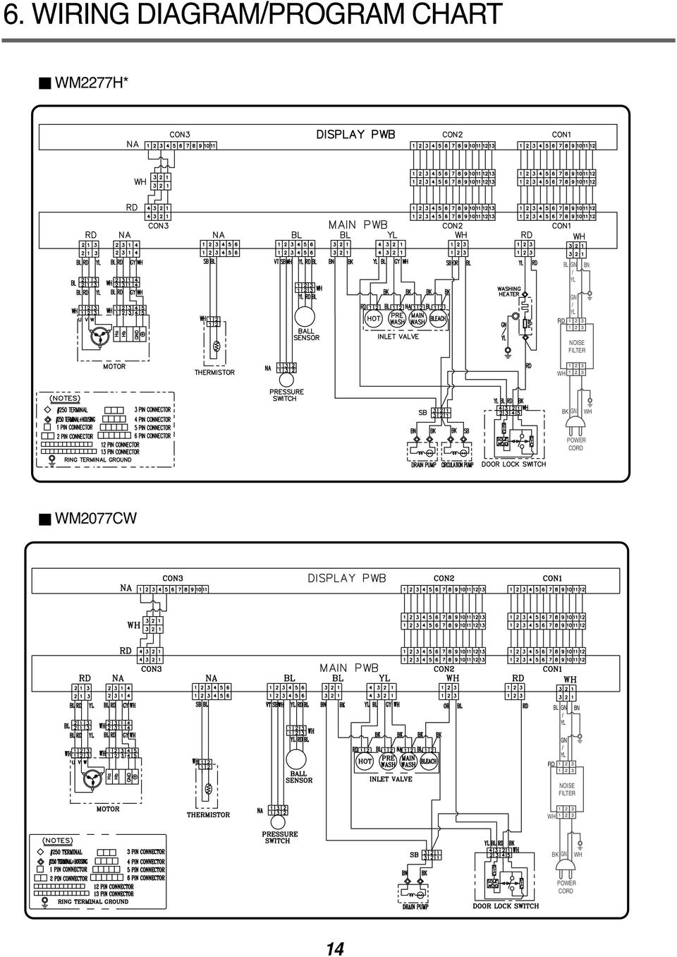
16 WM2177H* BL GN / YL BN RD GN / YL ISE FILTER WH BK GN WH POWER CORD WM2677H*M CON3 NA DISPLAY PWB CON2 CON WH INLET VALVE RD CON3 MAIN PWB CON2 CON1 RD NA NA BL BL YL WH RD WH BL BL RD YL BL RD GY WH SB BL VT SB WH YL RD BL BN BK YL BL GY WH SB OR BL YL RD BL GN BN YL RD BK / BL WH YL BL RD YL BL RD GY WH WH WH U V W WH 1 2 Ha Hb GND THERMISTOR MOTOR (TES) #250TERMINAL 3PIN CONNECTOR #250TERMINAL+HOUSING 4PIN CONNECTOR 1PIN CONNECTOR 5PIN CONNECTOR 2PIN CONNECTOR 6PIN CONNECTOR 12PIN CONNECTOR 13PIN CONNECTOR RING TERMINAL GROUND NA PRESSURE SWITCH WH YL RD BL BALL SENSOR BK BK BK BK RD BL NA BL BN HOT VALVE PRE WASH SB DRAIN PUMP MAIN WASH BLEACH BK BK BK SB CIRCULATION PUMP GN / YL WASHING HEATER P T C SOLE ID FUSE RD P T C DOOR LOCK SWITCH GN / YL RD ISE FILTER YL BL RD BK WH WH BK GN POWER CORD WH BK 8 BK YL WH PLC MODEM

17 Cool-down **Approx. (Minutes) * * * Wash time is in minutes. ** The total working time will vary with the load size, water temperature and ambient temperature. 16

18 7. TROUBLESHOOTING 7-1. BEFORE PERFORMING SERVICE Be careful of electric shock when disconnecting parts while troubleshooting. The voltage of each terminal is 110/120 V AC and DC when the unit is plugged in QC TEST MODE. The washer must be empty and the controls must be in the off state. 1. Press the SPIN SPEED and SOIL LEVEL buttons simultaneously. 2. Press the Power button, while the above condition. Then buzzer will sound twice. 3. Press the Start/Pause button repeatedly to cycle through the test modes. Number of times the Start/Pause button is pressed None Check Point Turns on all lamps and locks the door. Display Status 1 time Tumble clockwise. rpm (40~50) 2 times Low speed Spin. rpm 3 times High speed Spin. rpm 4 times Inlet valve for prewash turns on. Water level frequency (25~65) 5 times Inlet valve for main wash turns on. Water level frequency (25~65) 6 times Inlet valve for hot water turns on. Water level frequency (25~65) 7 times Inlet valve for bleach turns on. Water level frequency (25~65) 8 times Tumble counterclockwise. rpm (40~50) 9 times Heater turns on for 3 sec. Water temperature 10 times Circulation pump turns on. Water level frequency (25~65) 11 times Drain pump turns on. Water level frequency (25~65) 12 times Power off and unlock the door. Turn off all lamps. 1) : WM2277H*/WM2177H* : WM2677H*M : WM2077CW 7-3. HOW TO CHECK THE WATER LEVEL FREQUENCY Press the SPIN SPEED and SOIL LEVEL button simultaneously. The digits indicate the water level frequency ( x.1 khz ). So, for example a display indicating 241: a Water level frequency of 241 x.1 khz = 24.1 khz 17
 2 times Low speed Spin.")
19 7-4. ERROR DISPLAY If you press the START/PAUSE button when an error is displayed, any error except will disappear and the machine will go into the pause status. In case of if the error is not resolved within 20 sec., or the in case of other errors, if the error is not resolved within 4 min., power will be turned off automatically and the error code will blink. But in the case of, power will not be turned off. ERROR SYMPTOM CAUSE 1 2 WATER INLET ERROR IMBALANCE ERROR Correct water level (246) is not reached within 8 minutes after water is supplied or it does not reach the preset water level within 25 minutes. The load is too small. The appliance is tilted. Laundry is gathered to one side. Non distributable things are put into the drum. 3 DRAIN ERROR Not fully drained within 10 minutes. 4 OVER FLOW ERROR Water is overflowing (water level frequency is over 213). If is displayed, the drain pump will operate to drain the water automatically. 5 6 PRESSURE SENSOR ERROR DOOR OPEN ERROR The SENSOR SWITCH ASSEMBLY is out of order. Door not all the way closed. Loose electrical connections at Door switch and PWB Assembly. The DOOR SWITCH ASSEMBLY is out of order. 7 HEATING ERROR The THERMISTOR is out order. 18
 is not reached within 8 minutes after water is supplied or it does not reach the preset water level within 25")
20 ERROR SYMPTOM CAUSE 8 OVER CURRENT ERROR MAIN PWB ASSEMBLY is out of order. Winding in the STATOR ASSEMBLY is short-circuited LOCKED MOTOR ERROR BALL SENSOR ERROR The connector (3-pin, male, white) in the MOTOR HARNESS is not connected to the connector (3-pin, female, white) of STATOR ASSEMBLY. The electric contact between the connectors (3-pin, male, white) in the MOTOR HARNESS and 4-pin, female, white connector in the MAIN PWB ASSEMBLY is bad or unstable. The MOTOR HARNESS between the STATOR ASSEMBLY and MAIN PWB ASSEMBLY is cut (open circuited). The hall sensor is out of order/defective. Loose Ball Sensor Connector. Ball Sensor is out of order. Displayed only when the START/PAUSE button is first pressed in the QC Test Mode. 11 EEPROM ERROR EEPROM is out of order. Displayed only when the START/PAUSE button is first pressed in the QC Test Mode. 12 POWER FAILURE The washer experienced a power failure. 19
. The hall sensor is out of order/defective. Loose Ball Sensor Connector. Ball Sensor is out of order.")
21 8. ERROR DIAGSIS AND CHECK LIST 8-1. DIAGSIS AND SOLUTION FOR ABRMAL OPERATION SYMPTOM GUIDE FOR SERVICE CALL No power Is the power plug connected firmly to 120 V AC outlet? Power failure? or Breaker opened? Is the outlet controlled by a switch? Visit to service. Water inlet trouble Is displayed? Is the tap opened? Is the tap frozen? Is the water supply shut-off? Is filter in the inlet valve clogged with foreign material? Clean the filter of inlet valve Visit to service. 20
22 SYMPTOM GUIDE FOR SERVICE CALL Door error Was the load too large? Visit to service. Drain trouble Visit to service. 21
23 SYMPTOM GUIDE FOR SERVICE CALL Suds overflow from the appliance. (In this condition, wash and spin do not operate normally) Is a low-sudsing detergent used? Is the proper amount of detergent used as recommended? Recommend to reduce the amount of detergent. LOW-SUDSING This appliance has an automatic suds sensing function which prevents overflow. When excessive suds are sensed, the suds removing implementations such as drain, water input, pause will operate, without rotating the drum. Liquid laundry products do not flow in. Is liquid laundry product put in the correct compartment of the dispenser? Is the cap clogged? Explain proper use of liquid laundry products. Clean the compartment. Visit to service. 22
24 8-2. FAULT DIAGSIS AND TROUBLESHOOTING CAUTION 1. Be careful of electric shock if disconnecting parts while troubleshooting. 2. First of all, check the connection of each electrical terminal with the wiring diagram. 3. If you replace the MAIN PWB ASSEMBLY, reinsert the connectors correctly. POWER Is the supplied voltage 110/120 V AC? Check the fuse or reset the circuit breaker. Connector Is the voltage between the 2 FILTER ASSEMBLY connectors 120 V AC? Replace the FILTER ASSEMBLY (CIRC). Is the LED (1) on? Replace MAIN PWB ASSEMBLY. Are the connectors (2) on the PWB loose? Reconnect. Is wire of the DISPLAY PWB ASSEMBLY broken? Replace the MAIN PWB ASSEMBLY. Replace DISPLAY PWB ASSEMBLY or repair wire. 23
25 VIBRATION & ISE IN SPIN Have all the transit bolts and base packing been removed? Remove the transit bolts and Base packing. Is the washer installed on a solidly constructed floor? Move the washer or reinforce the floor. Base Packing Check if the washer is perfectly level as follows: Level Check the leveling of the washer with a Level and check that the washer is stable. Put an unbalance part (rubber) inside of drum and start QC test mode and run in high spin (Refer to section 7-2). When the machine is spinning in high speed, verify that it is stable. Unbalance Part If you do not have the unbalance part, put 4.5 to 6.5 lbs (2 to 3 kg) of clothing. Once loaded, press power, Rinse+Spin and the start/pause button in sequence. When the machine is spinning in high speed, verify that it is stable. Lock Nut Adjustable feet Higher If it is not stable, adjust feet accordingly. After the washer is level, tighten the lock nuts up against of the base of the washer. All lock nuts must be tightened. Lower Adjustable feet 24
26 If it still has severe vibration and noise, regulate a specific spin speed that generates excessive vibration and noise as follows: 1) Put an unbalance part (rubber) inside of the drum. 2) Start the QC test mode (Refer to section 7-2). 3) Press Delay Wash button, then is displayed. 4) Press the Spin Speed button repeatedly to select Extra High. 5) Press the Quick Cycle button, the spin speed is displayed. 6) Press the Start/Pause button. 7) Press the Beeper button repeatedly to set spin speed (600, 900, 1020, 1120 rpm) and check if there is vibration and noise. 8) If there is no vibration and noise, increase the spin speed by pressing Beeper button. 9) If there is vibration and noise, rotate the Cycle selector knob clockwise to reduce the Spin Speed (reduce by 50 and 100 rpm). In case of 600 rpm, it can not reduce the spin speed. 10) If vibration and noise are reduced, press the Quick Cycle button to store (2 beep sounds). * If you want to return to factory default spin speed setting, repeat above steps except step 9). 25
27 WATER SUPPLY Is water supply shut-off? Is the tap opened? When you press both SPIN SPEED button and SOIL LEVEL button simultaneously, is the water level frequency below 246? Is the inlet valve filter clogged? Is resistance between each terminal of INLET VALVE ASSEMBLY kω? Open the tap. Check the AIR CHAMBER and the tube (clogged). Clean the filter. Replace the INLET VALVE ASSEMBLY. Verify the voltage of the inlet valve connector is 120 V AC. (Refer to 7-2 QC TEST MODE) Check electrical connection. Replace the MAIN PWB ASSEMBLY. DETERGENT DOES T FLOW IN Is water supplied? Refer to WATER SUPPLY Are receptacles correctly connected to the terminals of the INLET VALVE ASSEMBLY? Check the wiring. Put the detergent in the correct place. Has detergent been put in the correct compartment of the dispenser? Is the detergent caked or hardened? Clean the dispenser. 26
28 LIQUID DETERGENT/SOFTENER/BLEACH DOES T FLOW IN Hot water Prewash Bleach Is water supplied? Refer to WATER SUPPLY Main wash Are the plugs correctly connected to the terminals of the INLET VALVE ASSEMBLY? Check the wiring on the dispenser. Is liquid detergent/softener/bleach put in the correct compartment of the drawer? Put it in the correct compartment. Bleach cap SOFTENER Is the liquid detergent/softener/bleach cap clogged? Clean the Cap and Container. Softener cap Liquid detergent cap ABRMAL SOUND Is the motor bolt loosened? Secure the bolt. Is there friction noise coming from the motor? Replace the STATOR ASSEMBLY or ROTOR ASSEMBLY. 27
29 HEATING WITHOUT WATER When pressing SPIN SPEED and SOIL LEVEL at the same time after draining, is the water level frequency 255? When pressing SPIN SPEED and SOIL LEVEL buttons at the same time while washing, is the water level frequency between ? Replace the SENSOR SWITCH ASSEMBLY. Check the voltage between two pins while pressing the POWER button. Is the voltage 120 V AC? Replace the MAIN PWB ASSEMBLY. DRAIN MALFUNCTION Is the drain hose twisted or frozen? Repair the DRAIN HOSE ASSEMBLY. Is the impeller of the drain pump clogged? Remove foreign material. Is the connector disconnected, disassembled? Reconnect or repair the connector Is the coil of the drain pump too high or low? (resistance of the coil is Ω) Replace the DRAIN PUMP ASSEMBLY. When checking voltage between connectors during spin, is the voltage 120 V AC as in the figure? Replace the MAIN PWB ASSEMBLY. 28
30 WASH HEATER TROUBLE HEATING CONTINUOUSLY ABOVE THE SETTING WATER TEMPERATURE Extra Hot: 70 C (1) 25 When checking the THERMISTOR on the tub, is the THERMISTOR loose? Push the THERMISTOR tightly to the rubber. 29
31 WILL T CIRCULATE WATER Is the impeller of the drain pump clogged? Remove foreign material. Hose Hose Connector (White) Are the Hose Connector and/or Hose clogged? Remove foreign material. Connector Is the connector disconnected, disassembled? Reconnect or repair the connector. Connector Is the coil of the right side of drain pump open or short circuited? (Coil R is Ω) Replace PUMP MOTOR ASSEMBLY. When checking voltage between the connectors during spin, is the voltage 120 V AC, as the figure? Replace the MAIN PWB ASSEMBLY. 30
32 SPIN TROUBLE Check during spin if the frequency of the water level is 248 or more. Check the SENSOR SWITCH ASSEMBLY or HOSE (Pressure). If the problem is on the SENSOR SWITCH ASSEMBLY or the HOSE, replace the SENSOR SWITCH ASSEMBLY or the HOSE. Press the START/PAUSE button 2 times in QC Test mode, is the drum spinning at low speed? Normal Is it disconnected, or disassembled? [Red: 3pin (1), NA: 4pin (2)] Correct the connection. (1) (2) Check the motor connector, Is the resistance of the terminal the same as the figure? MOTOR TERMINAL Resistance of terminal: About 5 Ω 15 Ω Replace the STATOR ASSEMBLY Replace the MAIN PWB ASSEMBLY Does the spring of Latch Hook actuate? Replace Door Assembly. (1) Is there clicking sound once or twice when the START/PAUSE button is pressed to start the cycle? Check the DOOR SWITCH ASSEMBLY Connector and MAIN PWB ASSEMBLY (Red 3 pin, Yellow 4 pin and white 3 pin connector (1)). Is DOOR SWITCH ASSEMBLY broken? 31 Replace the DOOR SWITCH ASSEMBLY.
33 9. DISASSEMBLY INSTRUCTIONS Be sure to unplug the machine out of the outlet before disassembling and repairing the parts. TOP PLATE ASSEMBLY Unscrew 2 screws on the back of the top plate. Pull the top plate backward and upward as shown. DRAWER Disconnect the Display PWB Assembly connector from Trans cable. Pull out the drawer and unscrew 2 screws. Lift the left side of the Control Panel Assembly and pull it out. CONTROL PANEL ASSEMBLY DISPLAY PWB ASSEMBLY Unscrew the 9 screws from the Control Panel Assembly. Disassemble the Display PWB Assembly. 32
34 Disconnect the POWER connector and SENSOR SWITCH ASSEMBLY. Remove the Protect Cover. CONNECTOR PROTECT COVER Disconnect the connectors. Unscrew 1 screw on the back. Disassemble the Main PWB. 33
35 Disassemble the top plate assembly. Pull out the drawer. Push out the DISPENSER ASSEMBLY after unscrew 2 screws. Unscrew the nut at the lower part of the dispenser. Disassemble the 4 connectors from the valves. Wire Color Blue Housing (OR-BK) White Housing (WH-BK) Blue Housing (GY-BK) Red Housing (BL-BK) Unscrew 2 screws from the back of the cabinet. Disassemble two (or three) connectors from the ISE FILTER. Unscrew a screw from the TOP BRACKET. 34
36 Unscrew the 4 screws from upper of the canbinet cover. Unscrew the screw from filter cover. Put a flat ( - ) screwdriver or putty knife into the both sides of the filter cover, and pull it out. Unscrew the screw from the lower side of the cabinet cover. 35
37 Open the door. Disassemble the clamp assembly. Tilt the cabinet cover. Disconnect the door switch connector. TE: When assembling the CABINET COVER, connect the connector. Lift and separate the cabinet cover. Disassemble the clamp assembly. Disassemble the Gasket. 36
38 Open the door. Unscrew the 7 screws from the HINGE COVER. Put a flat ( - ) screwdriver into the openng of the hinge, and pull out the hinge cover. Unscrew a screw from the lower side of door. Disassemble the door upward. Be careful! The door is heavy. Open the door and disassemble the CLAMP ASSEMBLY. Unscrew the 2 screws. TE Reconnect the connector after replacing the DOOR SWITCH ASSEMBLY. 37
39 Disassemble the cabinet cover. Separate the pump hose, the bellows and the circulation hose assembly from the pump assembly. Disassemble the pump assembly in arrow direction. Disassemble the cabinet cover. Separate 2 connectors from the heater. Loosen the nut and pull out the heater. CAUTION When assembling the heater, insert the heater into the heater clip on the bottom of the tub. Tighten the fastening nut so the heater is secure. Disassemble the cabinet cover. Unplug the white connector from the thermistor. Pull it out by holding the bracket of the thermistor. 38
40 Disassemble the cabinet cover. Separate the heater from the tub. Remove any foreign objects (wire, coin, etc.) by inserting a long bar in the opening. Unscrew the 4 screws from the back cover. Unscrew the single screw from the lower-right side of the cabinet. Disconnect the connector from PWB Harness. 39
41 Disassemble the back cover. Remove the bolt. Pull out the Rotor. Unscrew the 2 screws from the tub bracket. Remove the 6 bolts on the stator. Unplug the 2 connectors from the stator. Disassemble the damper hinges from the tub and base. Separate the dampers. TE Once removed, replace the damper pin with new one. 40
42 10. EXPLODED VIEW CABINET & CONTROL PANEL ASSEMBLY F215 A485 F210 F110 A455 A450 A102 A104 A105 A410 A150 A110 A111 A103 A490 A152 A154 A495 A101 A141 A390 A151 A153 A131 A100 A130 A430 A140 A133 A440 A155 A310 A300 A201 A220 A303 A200 41
43 DRUM & TUB ASSEMBLY K123 K143 K360 K350 K351 F140 K411 K410 K110 K111 K140 K320 K310 K510 K115 K131 K512 K560 K311 F315 F465 K125 F466 F467 K550 F463 K130 K530 F464 K121 K122 K610 K611 K141 F310 F145 K345 F468 K520 F461 K540 K105 K135 K340 K344 K346 K342 K571 K572 K570
44 10-3. DISPENSER ASSEMBLY F323 F322 F462 F321 F300 F170 F227 F226 F160 F225 F436 F430 F220 F431 F441 F440 F435 F120 A275 A276 HOT (RED) COLD (BLUE) F130 F432 43
45 REPLACEMENT PARTS LIST CAUTION : Before replacing any part of these components Read carefully the safety precautions in this manual Æ TE : S(Safety Parts), AL(Alternative parts) LG MODEL: WD-11270BD.ABWEEUS Run_Date : YOUR MODEL: WM2277HW SPECIFICATION: 120V 60Hz S AL LOC DESCRIPTION PARTS No. Q'TY REMARKS *001 MANUAL ASSEMBLY,OWNERS 3829ER3021Q 1 *002 BOX,CARTON 3890EZ3524A 1 *003 SPANNER 3W20018B 1 *004 MANUAL,SERVICE 3828ER3018Y 0 *005 MANUAL,OWNERS 3828ER3024X 0 A100 CABINET ASSEMBLY 3091ER0004A 1 A101 COVER,BACK 3808FR1202A 1 A102 BUSHING 4830ER3001A 1 A103 HOLDER 4930FR3151A 1 A104 BOLT ASSEMBLY 4011FR3159E 2 A105 BOLT ASSEMBLY 4011FR3159D 2 A110 TOP PLATE ASSEMBLY 3457ER1006C 1 A130 COVER,CABINET 3550ER0009B 1 A133 CLAMP ASSEMBLY 2W20017E 1 A140 HINGE ASSEMBLY 4775ER2002A 1 A150 DOOR ASSEMBLY 3581ER1008A 1 A151 DOOR FRAME,OUTER 3212ER1023A 1 A152 DOOR FRAME,INNER 3212ER1016A 1 A153 HANDLE 3650ER2004A 1 A155 HANDLE 3650FA3488M 4 A200 BASE ASSEMBLY,CABINET 3041ER0001C 1 A220 LEG ASSEMBLY 4779ER3002A 4 A275 HOSE,INLET 5215FD3715G 1 A276 HOSE,INLET 5215FD3715H 1 A300 CASE 3110ER2003A 1 A303 CAP,COVER 5006FR3146D 1 A310 CAP,COVER 5006ER2003A 1 A410 SWITCH ASSEMBLY,SENSOR SWITCH 6600FA1704X 1 A430 POWER CORD ASSEMBLY 6411ER1005A 1 A440 SWITCH ASSEMBLY,DOOR 6601ER1004C 1 A450 PWB(PCB) ASSEMBLY,MAIN 6871EC1087C 1 A455 COVER,PROTECT 3550ER1020A 1 A485 FILTER ASSEMBLY(CIRC) 6201EC1004U 1 A490 BRACKET ASSEMBLY 4811ER3001A 1 A495 SENSOR ASSEMBLY 6501FA2462C 1 F110 PWB(PCB) ASSEMBLY,DISPLAY 6871EC1116A 1 F120 HARNESS,PWB 6877ER1023C 1 F130 CABLE,FLAT 6850EC2001A 1 F140 HARNESS,MOTOR 6877ER1016B 1 F141 HARNESS,MOTOR 6877ER3003B 1 F160 VALVE ASSEMBLY,INLET 5221ER1003A 1 F170 VALVE ASSEMBLY,INLET 5220FR2006H 1 F210 PANEL ASSEMBLY,CONTROL 3721ER1126A 1 F215 KB ASSEMBLY 4941ER3002A 1 F220 PANEL ASSEMBLY,DRAWER 3721ER1073D 1 F225 CAP,SOFTENER 5006ER3014B 1 F226 CAP,SIPHONE 5006ER3018A 1 F227 BOX ASSEMBLY,DETERGENT 3891ER2003A 1 F300 DISPENSER ASSEMBLY 4925ER1015B 1 F310 BELLOWS 4738ER1004B 1 F315 BELLOWS 4738ER2002A 1 F321 HOSE,INLET 5214ER4001A 1 F322 HOSE,INLET 5214ER4001B 2 F323 HOSE,INLET 5214ER4001J 1 44
46 LG MODEL: WD-11270BD.ABWEEUS Run_Date : YOUR MODEL: WM2277HW SPECIFICATION: 120V 60Hz S AL LOC DESCRIPTION PARTS No. Q'TY REMARKS F430 HOSE ASSEMBLY,DRAIN 5215ER2002G 1 F431 CONNECTOR (MECH),DRAIN HOSE 4932FR3156A 1 F435 HOSE,DRAIN 5214FD3663E 1 F436 HOSE,INLET 5214FR4125S 1 F440 HOSE,PUMP 5214FR3188K 1 F441 CLAMP 4861FR3068C 3 F461 CLAMP 4861FR3068E 1 F463 CLAMP 4860FR3092D 2 F464 CLAMP 4860FR3092C 1 K101 TUB,OUTER 3044ER0003A 1 K105 TUB ASSEMBLY,OUTER[SUB4] 3045ER0008F 1 K110 TUB ASSEMBLY,INNER[DRUM] 3045ER1006A 1 K111 LIFTER ASSEMBLY 4433ER1001A 3 K115 SPIDER 4434ER0001A 1 K121 BEARING,BALL 4280FR4048D 1 K122 BEARING,BALL 4280FR4048E 1 K123 BOLT ASSEMBLY 4040FR4051B 1 K125 SEAL 4036ER2004A 1 K140 COVER ASSEMBLY,TUB 3551ER0003G 1 K141 SEAL 4036ER4001B 1 K143 SCREW,DRAWING 1SZZFA4362C 16 K310 THERMISTOR ASSEMBLY 6322FR2046F 1 K320 HEATER ASSEMBLY 5301FR1158J 1 K340 MOTOR ASSEMBLY,PUMP 4681EA2001D 1 K343 CLAMP 4860FR3092C 1 K344 CASING,PUMP 3108ER1001A 1 K345 MOTOR ASSEMBLY,PUMP 4681EA2001C 1 K346 FILTER(MECH) 5230ER3002A 1 K350 STATOR ASSEMBLY 4417FA1994G 1 K360 ROTOR ASSEMBLY 4413EA1002B 1 K410 SPRING,HINGE 4970FR2084P 2 K411 HOLDER 4930FR3040A 2 K510 GASKET 4986ER0004A 1 K520 BELLOWS 4738ER1002A 1 K530 CLAMP ASSEMBLY 4861ER2001D 1 K531 CLAMP 4861FR3068E 2 K540 CHAMBER,AIR 3504ER3002A 1 K550 HOSE,INLET 5214FR4125Y 1 K610 DAMPER ASSEMBLY,FRICTION 4901ER2002B 3 K611 HINGE 4774FR3118B 6 45
47 REPLACEMENT PARTS LIST CAUTION : Before replacing any part of these components Read carefully the safety precautions in this manual Æ TE : S(Safety Parts), AL(Alternative parts) LG MODEL: WD-11275BD.ABPEEUS Run_Date : YOUR MODEL: WM2277HB SPECIFICATION: 120V 60Hz S AL LOC DESCRIPTION PARTS No. Q'TY REMARKS *001 MANUAL ASSEMBLY,OWNERS 3829ER3021Q 1 *002 BOX,CARTON 3890EZ3524A 1 *003 SPANNER 3W20018B 1 *004 MANUAL,SERVICE 3828ER3018Y 0 *005 MANUAL,OWNERS 3828ER3024X 0 A100 CABINET ASSEMBLY 3091ER0004E 1 A101 COVER,BACK 3808FR1202A 1 A102 BUSHING 4830ER3001A 1 A103 HOLDER 4930FR3151A 1 A104 BOLT ASSEMBLY 4011FR3159E 2 A105 BOLT ASSEMBLY 4011FR3159D 2 A110 TOP PLATE ASSEMBLY 3457ER1006H 1 A130 COVER,CABINET 3550ER0009D 1 A133 CLAMP ASSEMBLY 2W20017E 1 A140 HINGE ASSEMBLY 4775ER2002A 1 A150 DOOR ASSEMBLY 3581ER1008A 1 A151 DOOR FRAME,OUTER 3212ER1023A 1 A152 DOOR FRAME,INNER 3212ER1016A 1 A153 HANDLE 3650ER2004A 1 A155 HANDLE 3650FA3489B 4 A200 BASE ASSEMBLY,CABINET 3041ER0001C 1 A220 LEG ASSEMBLY 4779ER3002A 4 A275 HOSE,INLET 5215FD3715G 1 A276 HOSE,INLET 5215FD3715H 1 A300 CASE 3110ER2003B 1 A303 CAP,COVER 5006FR3146D 1 A310 CAP,COVER 5006ER2003C 1 A410 SWITCH ASSEMBLY,SENSOR SWITCH 6600FA1704X 1 A430 POWER CORD ASSEMBLY 6411ER1005A 1 A440 SWITCH ASSEMBLY,DOOR 6601ER1004C 1 A450 PWB(PCB) ASSEMBLY,MAIN 6871EC1087C 1 A455 COVER,PROTECT 3550ER1020A 1 A485 FILTER ASSEMBLY(CIRC) 6201EC1004U 1 A490 BRACKET ASSEMBLY 4811ER3001A 1 A495 SENSOR ASSEMBLY 6501FA2462C 1 F110 PWB(PCB) ASSEMBLY,DISPLAY 6871EC1116A 1 F120 HARNESS,PWB 6877ER1023C 1 F130 CABLE,FLAT 6850EC2001A 1 F140 HARNESS,MOTOR 6877ER1016B 1 F141 HARNESS,MOTOR 6877ER3003B 1 F160 VALVE ASSEMBLY,INLET 5221ER1003A 1 F170 VALVE ASSEMBLY,INLET 5220FR2006H 1 F210 PANEL ASSEMBLY,CONTROL 3721ER1126G 1 F215 KB ASSEMBLY 4941ER3002A 1 F220 PANEL ASSEMBLY,DRAWER 3721ER1073R 1 F225 CAP,SOFTENER 5006ER3014B 1 F226 CAP,SIPHONE 5006ER3018A 1 F227 BOX ASSEMBLY,DETERGENT 3891ER2003A 1 F300 DISPENSER ASSEMBLY 4925ER1015B 1 F310 BELLOWS 4738ER1004B 1 F315 BELLOWS 4738ER2002A 1 F321 HOSE,INLET 5214ER4001A 1 F322 HOSE,INLET 5214ER4001B 2 F323 HOSE,INLET 5214ER4001J 1 46
48 LG MODEL: WD-11275BD.ABPEEUS Run_Date : YOUR MODEL: WM2277HB SPECIFICATION: 120V 60Hz S AL LOC DESCRIPTION PARTS No. Q'TY REMARKS F430 HOSE ASSEMBLY,DRAIN 5215ER2002G 1 F431 CONNECTOR (MECH),DRAIN HOSE 4932FR3156A 1 F435 HOSE,DRAIN 5214FD3663E 1 F436 HOSE,INLET 5214FR4125S 1 F440 HOSE,PUMP 5214FR3188K 1 F441 CLAMP 4861FR3068C 3 F461 CLAMP 4861FR3068E 1 F463 CLAMP 4860FR3092D 2 F464 CLAMP 4860FR3092C 1 K101 TUB,OUTER 3044ER0003A 1 K105 TUB ASSEMBLY,OUTER[SUB4] 3045ER0008F 1 K110 TUB ASSEMBLY,INNER[DRUM] 3045ER1006A 1 K111 LIFTER ASSEMBLY 4433ER1001A 3 K115 SPIDER 4434ER0001A 1 K121 BEARING,BALL 4280FR4048D 1 K122 BEARING,BALL 4280FR4048E 1 K123 BOLT ASSEMBLY 4040FR4051B 1 K125 SEAL 4036ER2004A 1 K140 COVER ASSEMBLY,TUB 3551ER0003G 1 K141 SEAL 4036ER4001B 1 K143 SCREW,DRAWING 1SZZFA4362C 16 K310 THERMISTOR ASSEMBLY 6322FR2046F 1 K320 HEATER ASSEMBLY 5301FR1158J 1 K340 MOTOR ASSEMBLY,PUMP 4681EA2001D 1 K343 CLAMP 4860FR3092C 1 K344 CASING,PUMP 3108ER1001A 1 K345 MOTOR ASSEMBLY,PUMP 4681EA2001C 1 K346 FILTER(MECH) 5230ER3002A 1 K350 STATOR ASSEMBLY 4417FA1994G 1 K360 ROTOR ASSEMBLY 4413EA1002B 1 K410 SPRING,HINGE 4970FR2084P 2 K411 HOLDER 4930FR3040A 2 K510 GASKET 4986ER0004A 1 K520 BELLOWS 4738ER1002A 1 K530 CLAMP ASSEMBLY 4861ER2001D 1 K531 CLAMP 4861FR3068E 2 K540 CHAMBER,AIR 3504ER3002A 1 K550 HOSE,INLET 5214FR4125Y 1 K610 DAMPER ASSEMBLY,FRICTION 4901ER2002B 3 K611 HINGE 4774FR3118B 6 47
49 REPLACEMENT PARTS LIST CAUTION : Before replacing any part of these components Read carefully the safety precautions in this manual Æ TE : S(Safety Parts), AL(Alternative parts) LG MODEL: WD-10270BD.ABWEEUS Run_Date : YOUR MODEL: WM2077CW SPECIFICATION: 120V 60Hz S AL LOC DESCRIPTION PARTS No. Q'TY REMARKS *001 MANUAL ASSEMBLY,OWNERS 3829ER3024Q 1 *002 BOX,CARTON 3890EZ3524A 1 *003 SPANNER 3W20018B 1 *004 MANUAL,SERVICE 3828ER3018Y 0 *005 MANUAL,OWNERS 3828ER3024X 0 A100 CABINET ASSEMBLY 3091ER0004A 1 A101 COVER,BACK 3808FR1202A 1 A102 BUSHING 4830ER3001A 1 A103 HOLDER 4930FR3151A 1 A104 BOLT ASSEMBLY 4011FR3159E 2 A105 BOLT ASSEMBLY 4011FR3159D 2 A110 TOP PLATE ASSEMBLY 3457ER1006B 1 A130 COVER,CABINET 3550ER0009B 1 A133 CLAMP ASSEMBLY 2W20017E 1 A140 HINGE ASSEMBLY 4775ER2002A 1 A150 DOOR ASSEMBLY 3581ER1008F 1 A151 DOOR FRAME,OUTER 3212ER0005C 1 A152 DOOR FRAME,INNER 3212ER1016A 1 A153 HANDLE 3650ER2004C 1 A155 HANDLE 3650FA3488M 4 A200 BASE ASSEMBLY,CABINET 3041ER0001D 1 A220 LEG ASSEMBLY 4779ER3002A 4 A275 HOSE,INLET 5215FD3715G 1 A276 HOSE,INLET 5215FD3715H 1 A300 CASE 3110ER2003A 1 A303 CAP,COVER 5006FR3146D 1 A310 CAP,COVER 5006ER2003A 1 A410 SWITCH ASSEMBLY,SENSOR SWITCH 6600FA1704X 1 A430 POWER CORD ASSEMBLY 6411ER1005A 1 A440 SWITCH ASSEMBLY,DOOR 6601ER1004C 1 A450 PWB(PCB) ASSEMBLY,MAIN 6871EC1087F 1 A455 COVER,PROTECT 3550ER1020A 1 A485 FILTER ASSEMBLY(CIRC) 6201EC1004U 1 A490 BRACKET ASSEMBLY 4811ER3001A 1 A495 SENSOR ASSEMBLY 6501FA2462C 1 F110 PWB(PCB) ASSEMBLY,DISPLAY 6871EC1116C 1 F120 HARNESS,PWB 6877ER1023G 1 F130 CABLE,FLAT 6850EC2001A 1 F140 HARNESS,MOTOR 6877ER1016B 1 F141 HARNESS,MOTOR 6877ER3003C 1 F160 VALVE ASSEMBLY,INLET 5221ER1003A 1 F170 VALVE ASSEMBLY,INLET 5220FR2006H 1 F210 PANEL ASSEMBLY,CONTROL 3721ER1126B 1 F215 KB ASSEMBLY 4941ER3002A 1 F220 PANEL ASSEMBLY,DRAWER 3721ER1073H 1 F225 CAP,SOFTENER 5006ER3014B 1 F226 CAP,SIPHONE 5006ER3018A 1 F227 BOX ASSEMBLY,DETERGENT 3891ER2003A 1 F300 DISPENSER ASSEMBLY 4925ER1015B 1 F310 BELLOWS 4738ER1004B 1 F315 BELLOWS 4738ER2002A 1 F321 HOSE,INLET 5214ER4001A 1 F322 HOSE,INLET 5214ER4001B 2 F323 HOSE,INLET 5214ER4001J 1 48
50 LG MODEL: WD-10270BD.ABWEEUS Run_Date : YOUR MODEL: WM2077CW SPECIFICATION: 120V 60Hz S AL LOC DESCRIPTION PARTS No. Q'TY REMARKS F430 HOSE ASSEMBLY,DRAIN 5215ER2002G 1 F431 CONNECTOR (MECH),DRAIN HOSE 4932FR3156A 1 F435 HOSE,DRAIN 5214FD3663E 1 F436 HOSE,INLET 5214FR4125S 1 F440 HOSE,PUMP 5214FR3188K 1 F441 CLAMP 4861FR3068C 3 F461 CLAMP 4861FR3068E 1 F463 CLAMP 4860FR3092D 2 F464 CLAMP 4860FR3092C 1 K101 TUB,OUTER 3044ER0003C 1 K105 TUB ASSEMBLY,OUTER[SUB4] 3045ER0008G 1 K110 TUB ASSEMBLY,INNER[DRUM] 3045ER1006B 1 K111 LIFTER ASSEMBLY 4433ER1001B 3 K115 SPIDER 4434ER0001A 1 K121 BEARING,BALL 4280FR4048D 1 K122 BEARING,BALL 4280FR4048E 1 K123 BOLT ASSEMBLY 4040FR4051B 1 K125 SEAL 4036ER2004A 1 K140 COVER ASSEMBLY,TUB 3551ER0003H 1 K141 SEAL 4036ER4001B 1 K143 SCREW,DRAWING 1SZZFA4362C 16 K310 THERMISTOR ASSEMBLY 6322FR2046F 1 K340 MOTOR ASSEMBLY,PUMP 4681EA2001D 1 K343 CLAMP 4860FR3092C 1 K344 CASING,PUMP 3108ER1001B 1 K346 FILTER(MECH) 5230ER3002A 1 K350 STATOR ASSEMBLY 4417FA1994G 1 K360 ROTOR ASSEMBLY 4413EA1002B 1 K410 SPRING,HINGE 4970FR2084P 2 K411 HOLDER 4930FR3040A 2 K510 GASKET 4986ER0004B 1 K520 BELLOWS 4738ER1002A 1 K530 CLAMP ASSEMBLY 4861ER2001D 1 K531 CLAMP 4861FR3068E 2 K540 CHAMBER,AIR 3504ER3002A 1 K550 HOSE,INLET 5214FR4125Y 1 K610 DAMPER ASSEMBLY,FRICTION 4901ER2002B 3 K611 HINGE 4774FR3118B 6 49
SERVICE MANUAL WASHING MACHINE
 Website:http://www.LGEservice.com E-mail:http://www.LGEservice.com/techsup.html WASHING MACHINE SERVICE MANUAL! CAUTION READ THIS MANUAL CAREFULLY TO DIAGSE PROBLEMS CORRECTLY BEFORE SERVICING THE UNIT.
WASHING MACHINE READ THIS MANUAL CAREFULLY TO DIAGNOSE TROUBLE CORRECTLY BEFORE OFFERING SERVICE.
 website : http://www.lgeservice.com e-mail : http://lgeservice.com/techsup.html WASHING MACHINE SERVICE MANUAL CAUTION READ THIS MANUAL CAREFULLY TO DIAGSE TROUBLE CORRECTLY BEFORE OFFERING SERVICE. MODEL
All About. Servicing. Service Tech Hand Book. 2010 Electrolux Home Products Inc. 10200 David Taylor Drive Charlotte, NC 28262
 All About Servicing Service Tech Hand Book 2010 Electrolux Home Products Inc. 10200 David Taylor Drive Charlotte, NC 28262 Publication #5995588729 February 2011 Section 1 Basic Information Safe Servicing
TOP AND CABINET PARTS
 TOP AND CABINET PARTS AUTOMATIC WASHER 9 06 Printed in U.S.A. (drd) 1 Part No. Rev. A TOP AND CABINET PARTS 1 Literature Parts 8182271 Use & Care Guide 8182277 Tech Sheet 8182614 Energy Guide 8182196 Quick
BUILT-IN DISHWASHER INSTALLATION INSTRUCTIONS
 BUILT-IN DISHWASHER INSTALLATION INSTRUCTIONS PLEASE READ COMPLETE INSTRUCTIONS BEFORE YOU BEGIN LEAVE INSTALLATION INSTRUCTIONS AND USER'S GUIDE WITH OWNER ALL ELECTRIC WIRING AND PLUMBING MUST BE DONE
Error Codes: 02F. Model: 110.44832 200 (110. = Whirlpool) S/N: CSP 1903874 Type: 199-AKP 705/WT. Sears Kenmore/Whirlpool Front Load Washer
 S/N: CSP 1903874 Type: 199-AKP 705/WT. Sears Kenmore/Whirlpool Front Load Washer") Sears Kenmore/Whirlpool Front Load Washer Error Codes: 02F dlf Model: 110.44832 200 (110. = Whirlpool) S/N: CSP 1903874 Type: 199-AKP 705/WT SOURCE: www.applicancepartspros.com WHIRLPOOL FAULT CODES Whirlpool
Sears Kenmore/Whirlpool Front Load Washer Error Codes: 02F dlf Model: 110.44832 200 (110. = Whirlpool) S/N: CSP 1903874 Type: 199-AKP 705/WT SOURCE: www.applicancepartspros.com WHIRLPOOL FAULT CODES Whirlpool
Fully Automatic Washing Machine User manual
 Fully Automatic Washing Machine User manual This manual is for HWMP55-918 Please read this manual carefully before using. Retain it for future reference. CONTENTS CONTENTS Inside cover Parts 1 Safety precautions
OPL BASIC. Dosing System for Professional Laundry machines. Contents
 OPL BASIC Dosing System for Professional Laundry machines Contents 1 Getting Started. Page 2 2 Installation. Page 4 3 Set Up & Operation. Page 8 4 Maintenance & Accessories. Page 10 5 Troubleshooting Page
800-292-3279 916 638-0828
 800-292-3279 916 638-0828 http://easycleansystems.com/heaters/heater-parts.html VAL6 KBE5S and KBE5L Service manual KBE5S 1 2 Specifications Type VAL6 KBE5S Heat Output 111,000BTU/h Fuel Kerosene, Diesel
Service manual. Website: www.andico.com.au CAUTION - BEFORE SERVICING THE UNIT, READ THE SAFETY - PRECAUTIONS IN THIS MANUAL.
 Website: www.andico.com.au Service manual CAUTION - BEFORE SERVICING THE UNIT, READ THE SAFETY - PRECAUTIONS IN THIS MANUAL. - ONLY FOR AUTHORISED SERVICE PERSONNEL. MODELS: MPK1-09CR-QB8 MPK1-12ER-QB6
PRODUCT: WASHER / WASHER-DRYER COMBO MODEL: AW 120 / AW 122 / AW 125 AWD 120 / AWD 121 / AWD 129
 PRODUCT: WASHER / WASHER-DRYER COMBO MODEL: The information included in this Splendide Repair Manual may change without notice. Please see our web site www.splendide.com/service/docs.html for updates,
TOP AND CABINET PARTS For Models: WTW5500XW0, WTW5500XL0 (White) (Silver)
 (Silver)") TOP AND CABINET PARTS AUTOMATIC WASHER 5 10 Litho in U.S.A. (drd)(bay) 1 Part No. Rev. A TOP AND CABINET PARTS 1 Literature Parts Installation Instructions W10240509 English/French W10240510 Spanish W10280477
TOP AND CABINET PARTS AUTOMATIC WASHER 5 10 Litho in U.S.A. (drd)(bay) 1 Part No. Rev. A TOP AND CABINET PARTS 1 Literature Parts Installation Instructions W10240509 English/French W10240510 Spanish W10280477
Cooling system components, removing and installing
 Page 1 of 34 19-1 Cooling system components, removing and installing WARNING! The cooling system is pressurized when the engine is warm. When opening the expansion tank, wear gloves and other appropriate
EVANS ELECTRONIC TEMPERATURE CONTROL TROUBLESHOOTING GUIDE for systems equipped with electric coolant valve and external PC board.
 EVANS ELECTRONIC TEMPERATURE CONTROL TROUBLESHOOTING GUIDE for systems equipped with electric coolant valve and external PC board. This Troubleshooting Guide covers the electric coolant valve and control
Please read this manual carefully before using. Retain for future reference. Automatic Washing Machine User manual
 Automatic Washing Machine User manual This manual is for HWMP55-918 HWMP65-918 Please read this manual carefully before using. Retain for future reference. CONTENTS Product Overview 1 Safety Precautions
Thermo Top - Troubleshooting Tree
 Thermo Top - Troubleshooting Tree 07-15-2002 CAUTION Troubleshooting requires comprehensive knowledge about the structure and theory of operation of the Thermo Top heater. Troubleshooting and repairs may
DANGER DANGER. General Information. Safety Is Your Responsibility. Ordering Parts. Contact Information
 Safety Safety Is Your Responsibility DANGER To avoid personal injury or death, carefully read and understand all instructions pertaining to the Anthony Liftgates product. Do not attempt to install, operate,
TOP AND CABINET PARTS
 TOP AND CABINET PARTS AUTOMATIC WASHER 10 10 Litho in U.S.A. (drd) (psw) 1 Part No. W10337313 Rev. C TOP AND CABINET PARTS 1 Literature Parts Installation Instructions W10240509 English/French W10240510
Dehumidifier Users manual. For Models: DH45S DH65S
 Dehumidifier Users manual For Models: DH45S DH65S 950-0062-revD Jan. 9 2007 FORWARD The appearance of the units that you purchase might be slightly different from the ones described in the Manual, but
Cooling system components, removing and installing
 Engine BHW Cooling system components, removing and installing Page 1 / 24 19-1 Cooling system components, removing and installing Warning! When doing any repair work, especially in the engine compartment,
Portable Air Conditioner
 Portable Air Conditioner Owner's Manual Model:3 in 1 12,000 Btu/h Series 3 Please read this owner s manual carefully before operation and retain it for future reference. CONTENTS 1. SUMMARY...1 2. PORTABLE
Troubleshooting Guide for Dispenser Model #900172
 Troubleshooting Guide for Dispenser Model #900172 Q. The cold water is room temperature. A. There is a cold water thermostat control mounted to the back of the majority of our appliances. Simply unplug
Service Guide 12/27/03 TESTING, SERVICE & REPAIR GUIDE (For SH Space Heating Models & RA Water Heating Models)
") TESTING, SERVICE & REPAIR GUIDE (For SH Space Heating Models & RA Water Heating Models) WARNING - HIGH VOLTAGE AC electrical circuits are connected to this heater. Do not attempt any service work on the
TESTING, SERVICE & REPAIR GUIDE (For SH Space Heating Models & RA Water Heating Models) WARNING - HIGH VOLTAGE AC electrical circuits are connected to this heater. Do not attempt any service work on the
Installation Instructions 4508 4508S
 SYMPHONY Spread Lavatory Faucet with Speed Connect Drain Congratulations on purchasing your American Standard faucet with Speed Connect drain, a feature found only on American Standard faucets. Speed Connect
ENGINE FUEL FUEL FILTER... FUEL HEATER... INJECTOR... SUPPLY PUMP... COMMON RAIL... FUEL PRESSURE LIMITTER...
 FUEL FILTER............................ FUEL HEATER.......................... INJECTOR.............................. SUPPLY PUMP.......................... COMMON RAIL.......................... FUEL PRESSURE
Convection Ovens. BX Classic. Models BX4 / FG 189C, BX4-6040 / FG 158C, BX10 / FG 180C. Operator's Manual
 Convection Ovens BX Classic Models BX4 / FG 189C, BX4-6040 / FG 158C, BX10 / FG 180C Operator's Manual Belshaw Bros., Inc. 814 44 th Street NW, Suite 103 Auburn, WA 98001 USA Phone: 206-322-5474 Fax: 206-322-5425
Fleck 4650. Service Manual INSTALLATION AND START-UP PROCEDURE TABLE OF CONTENTS JOB SPECIFICATION SHEET
 Fleck 4650 Service Manual TABLE OF CONTENTS JOB SPECIFICATION SHEET...1 INSTALLATION AND START-UP PROCEDURE...1 CONTROL VALVE DRIVE ASSEMBLY...2 CONTROL DRIVE ASSEMBLY FOR CLOCK...3 BYPASS VALVE ASSEMBLY...4
Line to Refrigerator Ice/Water Dispenser
 Standard 18 Line to Refrigerator Ice/Water Dispenser Pump Module Bottled Water How The System Works The FLOJET Bottled Water Dispensing System was designed to pump water from a commercially available 5-gallon
JANUS INTERNATIONAL CORPORATION INSTALLATION INSTRUCTIONS Pantheon Mini Operator
 JANUS INTERNATIONAL CORPORATION INSTALLATION INSTRUCTIONS Pantheon Mini Operator The Janus Pantheon mini operator does not typically require the provision of any additional site requirements other than
Commercial code: 69068
 Model type: ARWXF129WNA Commercial code: 69068 General notes Technical Documentation guidelines ----------------------------------------------------------------------------------------------------------------------------------
Table of Contents. www.hunterfan.com. What to Expect with. Preparation. Tools Needed. Wiring. Hanging the Fan. Blades. Motor Housing.
 www.hunterfan.com Table of Contents What to Expect with Your Installation 30 inches Hanging the Fan Wiring 8 Maintenance, Operation & Cleaning Light Kit 13??? 14 1 9 Troubleshooting 11 5 Blades Motor Housing
TS93 EMR T/PT/TDE. Surface applied door closer
 TS EMR T/PT/TDE Surface applied door closer Installation instructions: Pull side track mount door closer with smoke detector (EMR T) Push side track mount door closer with smoke detector (EMR PT) Double
English. Symbols used to mark instructions...3. Congratulations...5 Getting the best results...5. Warnings...6 Operating Procedure...
 2 Contents Components Attachments Guidance Installation Operation Maintenance Service Technical Troubleshooting Symbols used to mark instructions...3 Included Attachments...4 Congratulations...5 Getting
Instruction Manual. Image of SP-3015 & SP-3815. Important Safeguards. Automatic Dispensing Hot Water Pot with Reboil Function
 Important Safeguards READ ALL INSTRUCTIONS BEFORE USE. Instruction Manual Automatic Dispensing Hot Water Pot with Reboil Function Image of SP-3015 & SP-3815 SP-3015: 3.0L SP-3815: 3.8L SP-3017: 3.0L (Stainless
USER INSTRUCTIONS FOR GET PORTABLE 12k BTU AIR CONDITIONER MODEL No. GPACU12HR
 USER INSTRUCTIONS FOR GET PORTABLE 12k BTU AIR CONDITIONER MODEL No. GPACU12HR CONTENTS Introduction Safety Notes Identification of parts Installation instructions Operation instructions Maintenance Troubleshooting
Operating Manual. Los Angeles Abrasion Machine HM-70A & HM-70AF
 Operating Manual Los Angeles Abrasion Machine HM-70A & HM-70AF Rev: 07/19/2012 PHONE: 800-444-1508 P.O. Box 200, Lewis Center, Ohio 43035-0200 FAX: 800-255-5314 740-548-7298 E-mail: [email protected]
USER INSTRUCTIONS FOR 10 LITRE PORTABLE DEHUMIDIFIER MODEL NO. DHMD102
 USER INSTRUCTIONS FOR 10 LITRE PORTABLE DEHUMIDIFIER MODEL NO. DHMD102 THANK YOU FOR CHOOSING YOUR NEW DEHUMIDIFIER. BEFORE USING THE UNIT READ THESE INSTRUCTIONS FULLY AND RETAIN THEM FOR FUTURE REFERENCE
Name of Equipment Silver King Model SKMCD1P/C1. This equipment chapter is to be inserted in the appropriate section of the Equipment Manual.
 Name of Equipment Silver King Model SKMCD1P/C1 This equipment chapter is to be inserted in the appropriate section of the Equipment Manual. Manufactured exclusively for McDonald s By Silver King Refrigeration,
123 Industrial Loop Road Paynesville, MN 56362 Phone: 1-800-864-1649 www.master-mfg.com MASTER MANUFACTURING MASTER GARDNER
 123 Industrial Loop Road Paynesville, MN 56362 Phone: 1-800-864-1649 www.master-mfg.com MASTER MANUFACTURING MASTER GARDNER Part Number PCD E3 009B MM Rev 1 Nov. 2010 INTRODUCTION The purpose of this manual
3. SEISCO PARTS & SERVICE REMOVAL AND REPAIR GUIDE
 4 3. SEISCO PARTS & SERVICE REMOVAL AND REPAIR GUIDE A. Changing the Control Board B. Replacing a Heating Element C. Thermistor Replacement D. High Limit Switch Replacement E. Level Detector Replacement
POSEIDON 2-29, 2-25 & 2-22 POSEIDON 2-29, 2-25 & 2-22 XT
 POSEION 2-29, 2-25 & 2-22 POSEION 2-29, 2-25 & 2-22 XT Repair Manual Index A. Safety precautions 3 B. Technical data 4 C. Structure 5-6. Service / Repair 7-23 E. Tools 24 F. Function 25-26 G. Electric
NO-FROST CUSTOMER SUPPORT INFORMATION INFORMATION ON THE NO-FROST TECHNOLOGY WHITE GOODS
 INFORMATION INFORMATION ON THE TECHNOLOGY The -Frost refrigerators are different from the other static refrigerators in terms of their operational system. In normal refrigerators, in the freezing section,the
COLOR VIDEO DOOR PHONE CDV-71BE/D
 COLOR VIDEO DOOR PHONE CDV-71BE/D 513-11, Sangdaewon-dong, Jungwon-gu, Seongnam-si, Gyeonggi-do, Korea Int l Business Dept. : Tel.; +82-31-7393-540~550 Fax.; +82-31-745-2133 Web site : www.commax.com Printed
OEM Manual MODEL 2350 ELECTRONIC DUAL CYLINDER SCALE
 OEM Manual MODEL 2350 ELECTRONIC DUAL CYLINDER SCALE Scaletron Industries, Ltd. Bedminster Industrial Park 53 Apple Tree Lane P.O. Box 365 Plumsteadville, PA 18949 USA Toll Free: 1-800-257-5911 (USA &
SERVICE MANUAL SPLIT SYSTEM ROOM AIR CONDITIONER SHARP CORPORATION SHARP CORPORATION CONTENTS
 SERVICE MANUAL SPLIT SYSTEM ROOM AIR CONDITIONER INDOOR UNIT AH-129 AH-MP14 OUTDOOR UNIT AU-129 AU-MP14 CONTENTS SPECIFICATIONS...2 EXTERNAL DIMENSIONS...4 WIRING DIAGRAMS...5 ELECTRICAL PARTS...6 MICROCOMPUTER
Max primary circuit temperature 90ºC Max primary circuit temp. 90ºC Max secondary circuit temperature 45ºC Max secondary circuit temp.
 EGLISH 1 Product description exchanger equipped with an electronic control unit and circulation pump for the primary circuit. All Aqua-Mex variants can be ordered with an interior coil of either titanium
PWC-500/1000/1010/1500
 SERVICE MANUAL for by Vertex Model PWC-500/1000/1010/1500 P/N man-7008 Table of Contents Introduction Cooler Set-up Remove Top Cover Remove/Replace Float Remove/Replace Hot Tank Faucet Repair Hot Tank
SMD Rework Station TABLE OF CONTENTS
 SMD Rework Station Thank you for purchasing the Hakko 50B SMD Rework Station. The Hakko 50B is designed to solder and desolder surface mounted devices with hot air. Please read this manual before operating
Nexus FS Point of Use Installation Guide
 Nexus FS Point of Use Installation Guide Nexus FS POU Install Guide:12152011:rev-12152011 Technical Specifications Dimensions: Height: 43.5 Width: 11.65 Depth: 15 Weight: 34.39 LBS Electrical Specs: Voltage:
Service Manual. Coffee maker Senseo Viva Café HD7825/30 10/05. Philips Consumer Lifestyle
 Coffee maker Senseo Viva Café Philips Consumer Lifestyle Service Manual PRODUCT INFORMATION - This product meets the requirements regarding interference suppression on radio and TV. - After the product
Economy Combo Heat Press Manual Model No.: ECH-800
 Economy Combo Heat Press Manual Model No.: ECH-800 CONTENTS I. Assembly Drawing -----------------------------------------------------------------------------------2 II. Technical Parameters ------------------------------------------------------------------------------2
GPS AutoSteer System Installation Manual
 GPS AutoSteer System Installation Manual Supported Vehicles John Deere Sprayers 4720 4630 4730 4830 AutoTrac Ready PN: 602-0227-01-A LEGAL DISCLAIMER Note: Read and follow ALL instructions in this manual
Installation and instruction manual for Laing DDC pumps
 Installation and instruction manual for Laing DDC pumps Application The Laing DDC series pumps are primarily used for the circulation of cooling liquid in liquid cooled computers. Construction - The Laing
Calor de Hogar. Av Tecnológico 735, PB. San Salvador Tizatlalli. Metepec, 52172, Edo de México. Teléfono (722) 216 3330 (55) 1163 6038
 216 3330 (55) 1163 6038") Calor de Hogar Av Tecnológico 735, PB San Salvador Tizatlalli Metepec, 52172, Edo de México Teléfono (722) 216 3330 (55) 1163 6038 www.calordehogar.com servicio@calordehogar. com [email protected]
Calor de Hogar Av Tecnológico 735, PB San Salvador Tizatlalli Metepec, 52172, Edo de México Teléfono (722) 216 3330 (55) 1163 6038 www.calordehogar.com servicio@calordehogar. com [email protected]
DIAMOND Retractable Rodding Robot Model SPRAYROD-R
 2004-12-21 2 1 (23) DIAMOND Retractable Rodding Robot Model SPRAYROD-R 2004-12-21 2 2 (23) Table of contents 1 TECHNICAL DESCRIPTION...4 1.1 MAIN DETAILS...5 1.2 COMPONENTS DESCRIPTION...5 1.2.1 Pneumatic
MACBlower Model Number: MAC40R MAC60R MAC80R MAC100R. MAC120R MAC150R MAC 200R Serial # www.macblowers.com
 MACBlower Model Number: MAC40R MAC60R MAC80R MAC100R MAC120R MAC150R MAC 200R Serial # Fuji Clean USA 41-2 Greenwood Road Brunswick, Maine 04011 207-406-2729 www.macblowers.com MACBlowers The Intelligent
Washing Machine Owner s Instructions B1485AV/ B1285AV/ B1285AS/ B1285A/ B1085A/ R1285AV/ R1085A/ F1285AV/ F1085A
 Washing Machine Owner s Instructions B1485AV/ B1285AV/ B1285AS/ B1285A/ B1085A/ R1285AV/ R1085A/ F1285AV/ F1085A Safety Precautions Congratulations on your purchase of this Samsung washing machine. These
Model 43AP Pneumatic Controller, Style B
 Instruction MI 011-476 January 1980 Model 43AP Pneumatic Controller, Style B Installation and Operation Model 43AP Controller continuously detects the difference between a process measurement and its set
WASHING MACHINE OWNER S MANUAL
 OWNER S MANUAL WASHING MACHINE Before beginning installation, read these instructions carefully. This will simplify installation and ensure that the washer is installed correctly and safely. Leave these
Aquamax Australia Pty Ltd ABN 17 138 189 689
 Aquamax Australia Pty Ltd ABN 17 138 189 689 AQUAMAX SERVICE MANUAL Stainless Steel Electric Water Heaters AQ0903010-A Revision: A Published: November 2012 E80 to E315 Series Contents Introduction... 3
IMPORTANT SAFETY RULES TO FOLLOW
 WARNING FLOOR & CARPET CLEANER Any piece of equipment can be dangerous if not operated properly. YOU are responsible for the safe operation of this equipment. The operator must carefully read and follow
Stainless Steel Single and Dual Circulation Kits
 Instruction Sheet P/N 160780 01 Stainless Steel Single and Dual Circulation Kits Introduction The single and dual high-pressure circulation kits allow you to vary and control the circulation rate of coating
Ceiling Fan Installation Instructions
 Ceiling Fan Installation Instructions 1525..series OWNER S MANUAL READ AND SAVE THESE INSTRUCTIONS Total fan wieght with light kit 1-1525-CUL-English INSTALLATION CH-545 Safety Tips WARNING: TO REDUCE
Gas Oven Repair Guide
 - /6 - Gas Oven Repair Guide [ FX70*, FX50*] Ver. Aug-0 Ignition Failure Cooktop ignition Oven ignition Heating defect Oven Cooktop Abnormal Flame Button, Motors Lamp Others Smell, Smoke, Noise No Display,
MG1532 & MG2032 MIXER-GRINDERS
 MIXER-GRINDER MG1532 & MG2032 MIXER-GRINDERS MODEL MG1532 ML-134099 7.5 HP Grind Motor + 1 HP Mix Motor MG1532 ML-134103 5 HP Grind Motor + 1 HP Mix Motor MG1532 ML-134100 7.5 HP Grind Motor + 1 HP Mix
Utility Distribution Systems
 Utility Distribution Systems 6/2012 A0011037 1 WARRANTY This equipment is warranted to be free from defects in materials and workmanship, under normal use and service, for a period of 12 months from date
COOLING SYSTEM Section Page
 5 COOLING SYSTEM Section Page 5.1 COOLANT PRE-HEATER... 5-3 5.2 COOLANT PUMP NON-EGR ENGINE... 5-7 5.3 COOLANT PUMP EGR ENGINE... 5-13 5.4 FRONT CONNECTOR HOUSING NON-EGR ENGINE... 5-17 5.5 FRONT CONNECTOR
SunMaxx Solar Filling Station Operating Instructions
 SunMaxx Solar Filling Operating Instructions Content 1. Declaration of conformity... 2 2. Introduction... 2 3. Transportation and unpacking... 4 4. Mounting and commissioning... 5 5. End of operation...
LUCCI AIRFUSION QUEST II CEILING FAN
 LUCCI AIRFUSION QUEST II CEILING FAN WITH IR REMOTE INSTALLATION OPERATION MAINTENANCE WARRANTY INFORMATION CAUTION READ INSTRUCTIONS CAREFULLY FOR SAFE INSTALLATION AND FAN OPERATION. V1.0 QUEST II IR
MODEL T600 40LB CAPACITY COMPUTER CONTROL COIN WASHER
 P/N 8514-097-001B MODEL T600 40LB CAPACITY COMPUTER CONTROL COIN WASHER DEXTER LAUNDRY, INC. OWNER'S BOOKLET INSTALLATION & OPERATION INSTRUCTIONS Please read this information and retain for reference.
Oil and Coolant Circulating Heating System. Model - OCSM
 Oil and Coolant Circulating Heating System Model - OCSM Installation & Operation Manual 216280-000 REV 2 Identifying Your System The HOTSTART heating system is designed to heat fluids for use in marine
Twin-tub Washing Machine
 Twin-tub Washing Machine SERVICE MANUAL MODEL NO.: DW-1100K NINGBO KINGSUN GROUP CO., LTD Please read this manual carefully before operating your Washing Machine. Please record model number and serial
accidents which arise due to nonobservance and the safety information herein.
 20 GALLON COMPRESSOR Model: 7342 CALIFORNIA PROPOSITION 65 WARNING: You can create dust when you cut, sand, drill or grind materials such as wood, paint, metal, concrete, cement, or other masonry. This
36G22, 36G23, 36G24 & 36G52 36J22, 36J23, 36J24 & 36J52 DSI and HSI Single Stage Combination Gas Valve
 Operator: Save these instructions for future use! FAILURE TO READ AND FOLLOW ALL INSTRUCTIONS CAREFULLY BEFORE INSTALLING OR OPERATING THIS CONTROL COULD CAUSE PERSONAL INJURY AND/OR PROPERTY DAMAGE. DESCRIPTION
SHOT BLAST CABINET MODEL NO: CSB20B
 SHOT BLAST CABINET MODEL NO: CSB20B PART NO: 7640110 USER INSTRUCTIONS GC0216 INTRODUCTION Thank you for purchasing this CLARKE Shot Blast Cabinet which is designed for professional workshop use. Before
Carpet Washer. vax.co.uk VRS5W. Vax Careline: (UK) 0844 412 8455 (ROI) 1-800 928 308. Vax model number: Version 1.0
 0844 412 8455 (ROI) 1-800 928 308. Vax model number: Version 1.0") VRS5W Powermax User Guide V1.0.qxd:V1.0 23/7/10 15:35 Page 1 Vax Careline: (UK) 0844 412 8455 (ROI) 1-800 928 308 Carpet Washer Vax model number: VRS5W instruction manual Version 1.0 Please read carefully
VRS5W Powermax User Guide V1.0.qxd:V1.0 23/7/10 15:35 Page 1 Vax Careline: (UK) 0844 412 8455 (ROI) 1-800 928 308 Carpet Washer Vax model number: VRS5W instruction manual Version 1.0 Please read carefully
REMOVAL AND INSTALLATION
 303-01C-1 REMOVAL AND INSTALLATION Engine Body On Special Tool(s) Adapter For 303-D043 303-D043-02 or equivalent Special Tool(s) 303-01C-1 Turbocharger Lifting Bracket 303-1266 Wrench, Fan Clutch Nut 303-214
CARING FOR YOUR WATER HEATER
 http://waterheatertimer.org/troubleshoot-rheem-tankless-water-heater.html Water Heater Inspections CARING FOR YOUR WATER HEATER Venting System (Direct Vent Only) The venting system should be inspected
Bauknecht AG, Industriestrasse 36, 5600 Lenzburg, www.bauknecht.ch
 Instructions for use WA 5555 Bauknecht AG, Industriestrasse 36, 5600 Lenzburg, www.bauknecht.ch Verkauf Telefon 0848 801 002 Fax 0848 801 017 [email protected] Kundendienst Telefon 0848 801 001 Fax
USER S MANUAL HSC-24A
 AIRREX AIR CONDITIONER USER S MANUAL HSC-24A Thank you for purchasing an AIRREX AIR CONDITIONER. BEFORE operation please read this user s manual carefully. Keep this manual readily available. It is ESSENTIAL
MODEL #12006. Introduction
 THE ORIGINAL PECO POWER SPRAYER PECO OWNER S MANUAL MODEL #12006 (Q0080) Revised: 1/8/2014 PECO POWER SPRAYER MODEL #12006 TABLE OF CONTENTS SECTION PAGE SECTION PAGE INTRODUCTION - - - - - - - - - - -
with MERCURY FREE 1 HP Relays ! WARNING Before using this product read and understand instructions.
 B Installation & Maintenance Instructions MM-414 Series 150E and 157E Low Water Cut-Off/Pump Controllers For Steam Boilers and Other Level Control Applications A Typical Applications: Primary or secondary
TECHNICAL SERVICE DEPARTMENT Technical Service Bulletin 1-800-432-8373. Tankless Electric (RTE) Troubleshooting
 Troubleshooting") Sequence of Operations 1 Power supply and field wiring block 2 Energy Cut Off (ECO) 3 Water flow plunger and cold inlet 4 Magnetic flow switch 5 Water temperature thermistor 6 Control panel and circuit
Sequence of Operations 1 Power supply and field wiring block 2 Energy Cut Off (ECO) 3 Water flow plunger and cold inlet 4 Magnetic flow switch 5 Water temperature thermistor 6 Control panel and circuit
Cleaning & Sanitisation
 Cleaning & Sanitisation Notice: The information and/or procedures presented in the following demonstration(s) should be performed by a trained Water Cooler Service Technician only. Never attempt to service
Bench Autoclave. Standard Operating Procedure. For Installation, Use and Maintenance
 Bench Autoclave Standard Operating Procedure For Installation, Use and Maintenance 1. Introduction This SOP is intended for use with the following model, in a laboratory context: Type: Nuve Bench Top Steam
Volkswagen Jetta, Golf, GTI 1999, 2000 Brake System 47 Brakes - Hydraulic Components (Page GR-47)
") 47 Brakes - Hydraulic Components (Page GR-47) FS III front brake calipers, servicing Front brake caliper piston, removing and installing FN 3 front brake calipers, servicing Front caliper piston, removing
47 Brakes - Hydraulic Components (Page GR-47) FS III front brake calipers, servicing Front brake caliper piston, removing and installing FN 3 front brake calipers, servicing Front caliper piston, removing
MAC FAUCETS. Owner s Manual. Models: FA444
 MAC FAUCETS Owner s Manual Models: FA444 Installation procedure: 1. Take a moment to view drawings and read special Installation note on page 3 of this manual before proceeding with installation. Connect
15GAL STEEL OIL DRAIN WITH 110V PUMP
 15GAL STEEL OIL DRAIN WITH 110V PUMP OWNER S MANUAL WARNING: Read carefully and understand all ASSEMBLY AND OPERATION INSTRUCTIONS before operating. Failure to follow the safety rules and other basic safety
INSTALLATION INSTRUCTIONS
 INSTALLATION INSTRUCTIONS Accessory Application Publications No. AII23628 2003 PILOT Issue Date MAY 2002 PARTS LIST Security System Kit (sold separately): P/N 08E51-S84-100 2 Remote controls Attachment
Si10-417_C. Pocket Manual. Service Diagnosis SPLIT & MULTI
 Pocket Manual Service Diagnosis SPLIT & MULTI Service Diagnosis SPLIT & MULTI 1. Troubleshooting with LED...5 1.1 Indoor Unit... 5 1.2 Outdoor Unit... 10 2. Troubleshooting by Symptoms...11 2.1 Air conditioner
MBSAW. Meat Cutting Band Saw With Meat Grinder Assembly & Operating Instructions
 06/2011 MBSAW Meat Cutting Band Saw With Meat Grinder Assembly & Operating Instructions READ ALL INSTRUCTIONS AND WARNINGS BEFORE USING THIS PRODUCT. This manual provides important information on proper
FlexFlash Instruction Manual Models SB FLXFLSH400W, SB FLXFLSH200W, SB FLXFLSHE400W, SB FLXFLSHE200W
 FlexFlash Instruction Manual Models SB FLXFLSH400W, SB FLXFLSH200W, SB FLXFLSHE400W, SB FLXFLSHE200W Rev 7/18/13 Accessory release button Flash tube Slave sensor Modeling lamp Repositionable swivel handle
Coffee Maker Senseo HD7820/70
 Coffee Maker Senseo Philips Domestic Appliances and Personal Care Service Manual PRODUCT INFORMATION - This product meets the requirements regarding interference suppression on radio and TV. - After the
SMART DRIVE ELECTRONIC WASHING MACHINE
 SMART DRIVE ELECTRONIC WASHING MACHINE MODEL GWL03US 120 Volt 60 Hz Fisher & Paykel Appliances Inc 27 Hubble, Irvine, California, CA92618, USA, Ph: 949 790 8900, Fax: 949 790 8911 426348 C O N T E N T
Portable Air Conditioner. OWNER S MANUAL Read these instructions before use. Model: MF08CESWW. Voltage rating: 115V~60Hz Power rating : 800W
 MODE ALARM Portable Air Conditioner OWNER S MANUAL Read these instructions before use 8 Model: MF08CESWW Voltage rating: 115V~60Hz Power rating : 800W Customer Support : 1-800-474-2147 For product inquiries
Model 2300DR Installation Guide
 Model 2300DR Installation Guide POWER ACCESS CORPORATION P.O. BOX 1050 170 MAIN STREET NEW HARTFORD, CT 06057 800-344-0088 WEBSITE: www.power-access.com EMAIL: [email protected] 1 STANDARD PARTS
Heat Surge Model X5C Fire Place Insert Service Manual Applies to all units w/30000208 circuit board
 Heat Surge Model X5C Fire Place Insert Service Manual Applies to all units w/30000208 circuit board 2012 HS M4417A BR16597R-1 HEAT SURGE 8000 FREEDOM AVE, N. CANTON, OH 44720 330-244-8161 WWW.HEATSURGE.COM
Volkswagen New Beetle 2.0 Liter 4-cyl General, Engine (Engine Code AEG) 17 Engine-Lubrication system (Page GR-17)
 17 Engine-Lubrication system (Page GR-17)") 17 Engine-Lubrication system (Page GR-17) Lubrication system components, removing and installing Oil pan, removing and installing Oil pressure and oil pressure switch, checking Dynamic oil pressure warning
17 Engine-Lubrication system (Page GR-17) Lubrication system components, removing and installing Oil pan, removing and installing Oil pressure and oil pressure switch, checking Dynamic oil pressure warning
BACKPACK SPRAYERS. MODEL NOS: KSP16 & KSP20 Part Nos: 3402270 & 3402275 OPERATING & MAINTENANCE INSTRUCTIONS GC04/12
 BACKPACK SPRAYERS MODEL NOS: KSP16 & KSP20 Part Nos: 3402270 & 3402275 OPERATING & MAINTENANCE INSTRUCTIONS GC04/12 INTRODUCTION Thank you for purchasing this CLARKE Sprayer, designed for use only with